Loading ...
Loading ...
Loading ...
2. Provide an adequate gas supply.
This unit is designed to operate on 4" natural gas or 10" LP/Propane
manifold pressure. A convertible pressure regulator is connected to
the manifold and MUST be connected in series with the gas supply
line regardless of which type of fuel is being used.
Care must be taken during installation of range not to obstruct the
flow of combustion and ventilation air.
For proper operation, the maximum inlet pressure to the regulator
should be no more than 14 inches of water column pressure. The
inlet pressure to the regulator must be at least 1 inch greater than
regulator manifold pressure. Examples: If regulator is set for
natural gas 4 inch manifold pressure, inlet pressure must be at
least 5 inches; if regulator has been converted for LP!Propane gas
10 inch manifold pressure, inlet pressure must be at least 11
inches.
Leak testing of the appliance shall be conducted according to the
instructions in step 4g.
The gas supply line should be 1/2" or 3/4" I.D.
120V Outlet on Rear of
Wall and Area for Thru
the Wall Connection of
Pipe Stub and Shut Off
Valve is Shaded Area.
Area for Thru _ - _ Wall
the Floor Connection of Edge
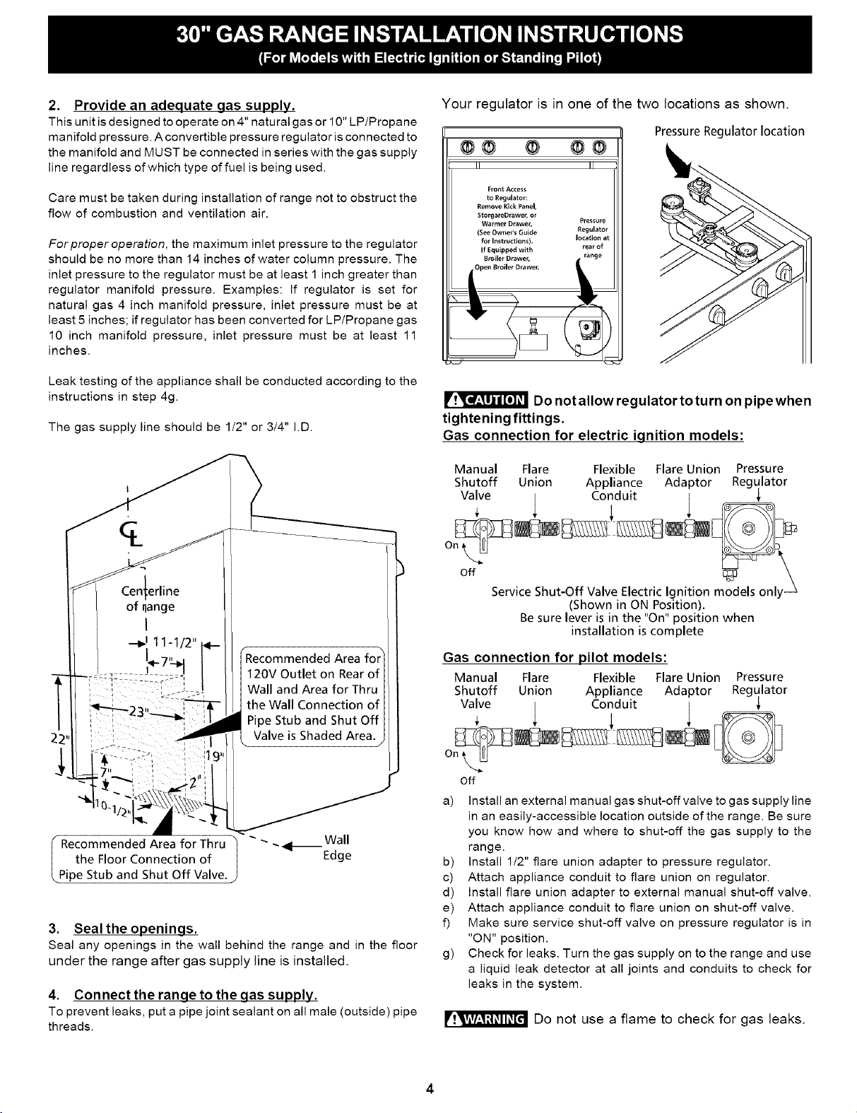
3. Seal the openings.
Seal any openings in the wall behind the range and in the floor
under the range after gas supply line is installed.
4. Connect the ranqe to the gas supply.
To prevent leaks, put a pipe joint sealant on all male (outside) pipe
threads.
Your regulator is in one of the two locations as shown.
@@ @ @@
Front Access
to Regulator:
Remove Kick Panel,
StorgareDrawer, or
Warmer Drawe_ Pressure
(See Owner's Guide Regulator
for Instructions), location at
If Equipped with rear of
Broiler Drawer,
Pressure Regulator location
Do not allow regulator to turn on pipewhen
tightening fittings.
Gas connection for electric ignition models:
Manual Flare Flexible Flare Union Pressure
Shutoff Union Appliance Adaptor Regulator
Valve ! Conduit |
off
Service Shut-Off Valve Electric Ignition models onlm'-'4_l_ _,,4y_X
(Shown in ON Position).
Be sure lever is in the "On" position when
installation is complete
Gas connection for pilot models:
Manual Flare Flexible Flare Union Pressure
Shutoff Union Appliance Adaptor Regulator
Valve | Conduit [
off
a) Install an external manual gas shut-off valve to gas supply line
in an easily-accessible location outside of the range. Be sure
you know how and where to shut-off the gas supply to the
range.
b) install 1/2" flare union adapter to pressure regulator.
c) Attach appliance conduit to flare union on regulator.
d) Install flare union adapter to external manual shut-off valve.
e) Attach appliance conduit to flare union on shut-off valve.
f) Make sure service shut-off valve on pressure regulator is in
"ON" position.
g) Check for leaks. Turn the gas supply on to the range and use
a liquid leak detector at all joints and conduits to check for
leaks in the system.
Do not use a flame to check for gas leaks.
4
Loading ...
Loading ...
Loading ...