Loading ...
Loading ...
Loading ...
9
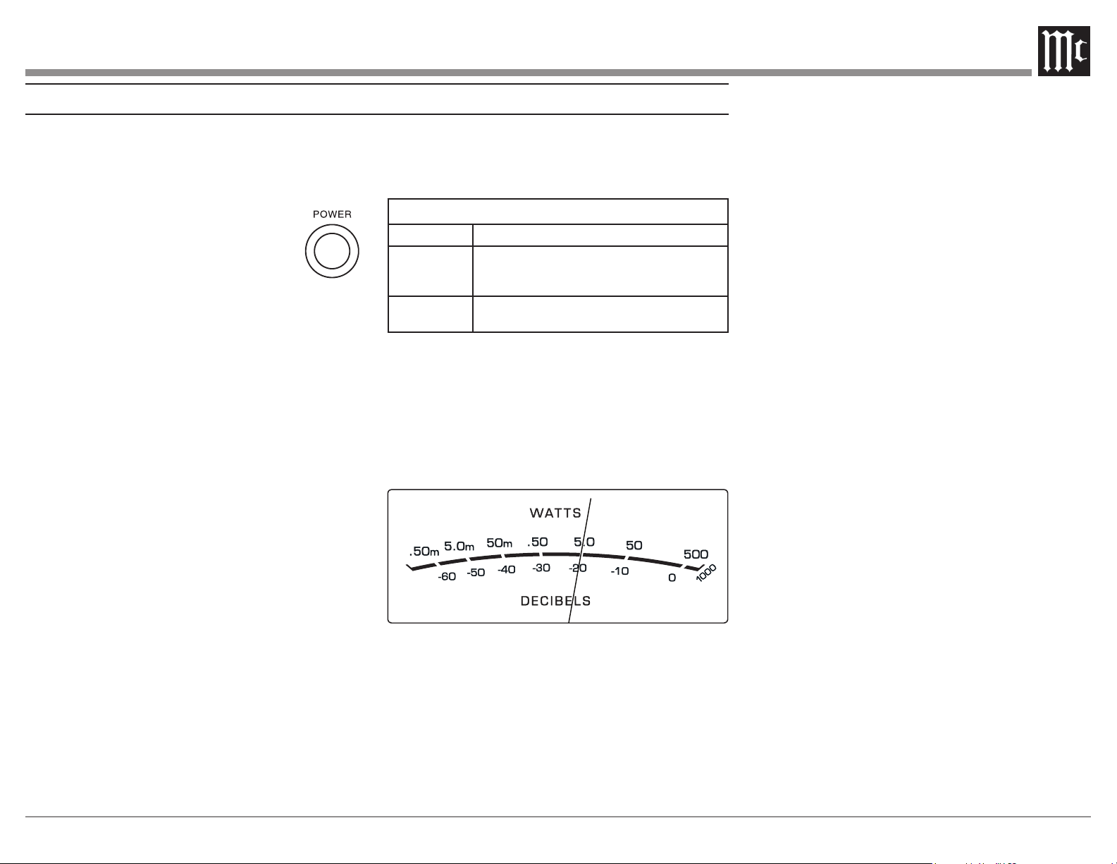
Power On
The LED STANDBY/ON Indicator illuminates to
indicate the MI502 is connected to AC Power. To
switch ON the MI502, press the POWER button on
the Front Panel or switch On the Audio
Source Component providing there is a
Power Control Cable Connection to the
Notes: 1. It will take about 6 seconds for the
MI502 to complete the initialization of
the internal circuitry when switched On.
2. There must be a power control connection between
the MI502 and the Audio Source Component in order
for the Remote Control Operation Power ON/OFF to
function.
3. When the MI502 is receiving a Power Control
ON Signal, the Front Panel POWER Push-Button
becomes inactive.
Auto O Function
The MI502 incorporates Power Save Circuitry to
automatically place the MI502 into the power saving
Standby Mode approximately 30 minutes after there
has been an absence of an audio input signal on both
channels.
When there is a Power Control Connection
Component, the AUTO OFF Function is bypassed.
Channel Operational Indication
The MI502 Front Panel has two LEDs. The LEDs
indicate the current functioning status for each of
the two channels.
MI502 Channel Operation Functions
LED COLOR
Functional Status
Amber
Indicates when maximum Power Output for the
Channel has occured with prevention of Audio
Clipping
Red
Indicates current limit or short circuit for the
Channel Loudspeaker Output Connection
Power Output Meters
The MI502 Power Output Meters indicate the
13. The meters respond to all the musical informa-
to an accuracy of at least 95% of the power output
with only a single cycle of a 2,000Hz tone burst.
How to Operate
Figure 12
Fig ure 13
Loading ...
Loading ...
Loading ...