Loading ...
Loading ...
Loading ...
4
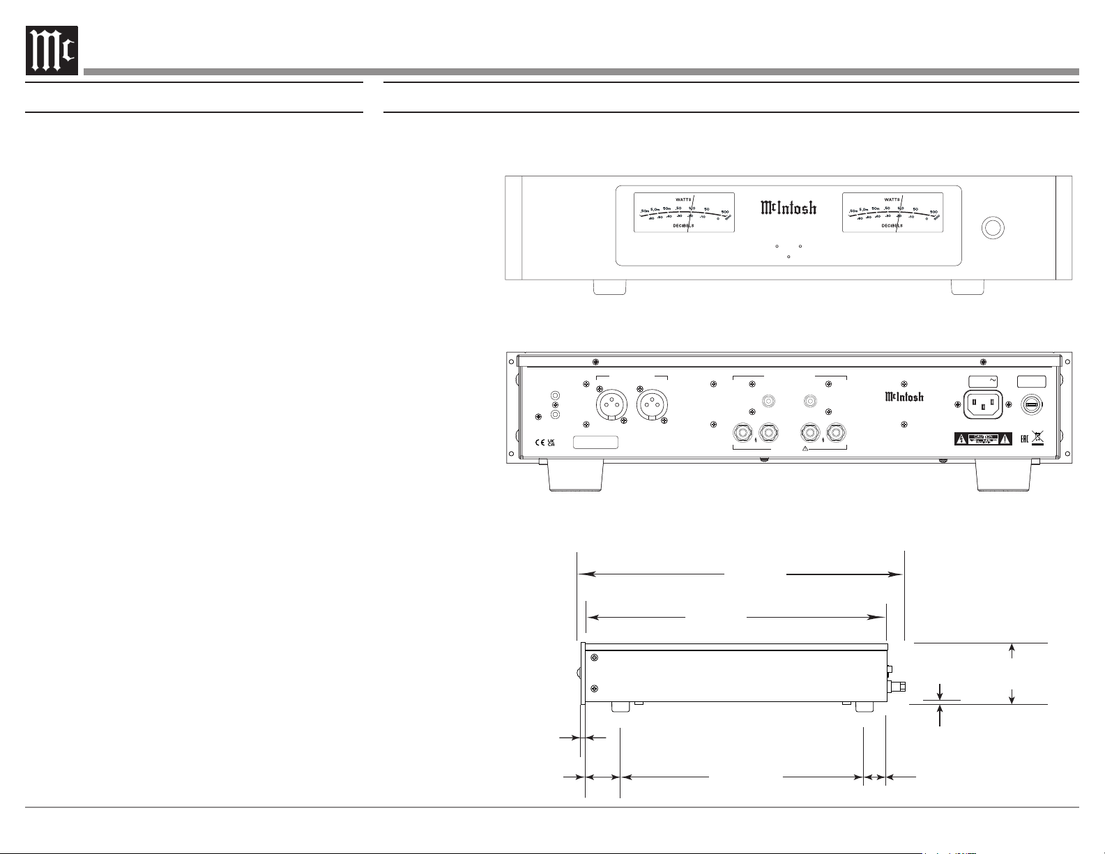
Rear View
Side View
17-1/2"
44.5cm
3-15/32"
8.8cm
4-5/16"
11.0cm
13-1/4"
33.7cm
18-1/2"
47.0cm
17-1/16"
43.3cm
.25"
.64cm
2.0"
5.0cm
13-19/32"
34.7cm
1-5/16"
3.4cm
3/16
"
.5cm
3-1/4"
8.2cm
Front View
with
Side Mount Brackets
19"
48.3cm
16-1/2"
41.9cm
SERIAL
NUMBER
CAUTION
RISK OF ELECTRIC SHOCK
DO NOT OPEN
ATTENTION:
RISQUE DE CHOC ELECTRIQUE-NE PAS OUVRIR
MI502 2 C HANNEL POWER AMPLIFIE R
McINTOSH LABORATORY, INC., BINGHAMTON, NY
HANDCRAFTED IN USA WITH US AND IMPORTED PARTS
POWER
CONTROL
IN
OUT
50/60Hz 10A
100V-240V
15AH 250V
LEFT
RIGHT
LEFTRIGHT
+
–
+
–
CLASS 2 WIRING
BALANCED INPUTS UNBALANCED INPUTS
LEFTRIGHT
OUTPUTS
Dimensions
The following dimensions can assist in determining the best location for your MI502.
Installation
The MI502 needs to be placed upright on its four
feet. It also can be custom installed. Remove the
four feet when it is custom installed and retain them
with the fastening screws for possible future use.
The required panel cutout, ventilation cutout and unit
dimensions are shown in the drawing on the right side
of this page.
It is necessary to provide adequate ventilation for
cool operation, ensuring long life for the MI502. Do
not install the MI502 above heat generating compo-
nents. When the MI502 is installed in a cabinet with
other components, use a ventilation fan to provide cool
operating temperature.
A custom cabinet installation needs to provide the
following minimum spacing for cool operation:
Allow at least 3 inches (7.6cm) above the top, 2
inches (5.08cm) below the bottom, 3 inches (7.62cm)
behind the rear panel and 2 inches (5.08cm) on each
(6.35 cm) in front of the mounting
1
panel for clearance.
Be sure to cut out a ventilation hole in the mounting
shelf according to the dimensions in the drawing.
1
When the MI502 is installed together with other McIntosh
Components, check clearances on all components
before proceeding.
Installation of Side Rack Mount Brackets
When desired, to install MI502 Side Rack Mounting
Brackets, follow the steps below for one side at a time:
1. Refer to figure 1 to remove the two side screws
and save them for possible future use.
2. Position the Side Rack Mounting Bracket as
illustrated in figure 2. Then attach the Bracket to
the Front and Side Panel of the MI502, using the
screws supplied with the Bracket.
3. Perform steps 1 and 2 to mount the second
Bracket to the other side of the MI502.
Front View
Rear View
POW ER
MI502
2 CHANNEL
PO WER A MPL IFI ER
Side View
Loading ...
Loading ...
Loading ...