Loading ...
Loading ...
3
Connector and Cable Information
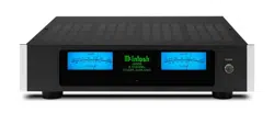
XLR Connectors
Balanced Input, Input/Output Connectors on the
MI502. Refer to the diagram for connection:
PIN 1: Shield/Ground
PIN 2: + Input/Output
PIN 3: - Input/Output
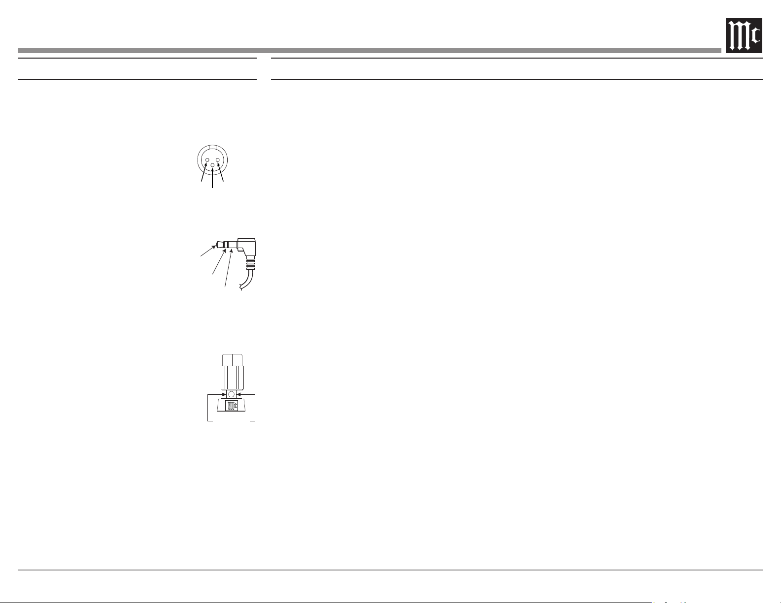
Power Control Connector
The MI502 Power Control Input receives an
Control Output will in turn
provide a +12 volt Output Signal
with a total current up to 50mA.
An additional connection is for
controlling the illumination of
the MI502 Meter Power Output Indicators. The
3.5mm stereo mini phone plug connects to a
Power Control Output.
Output Terminal Connector
When cables with spade lugs are
used for Loudspeaker Connection,
the spade lugs need an opening of at
least 3/10 inch (7.6mm)
Power
Control
Meter
Illumination
Control
Ground
3/10 of an inch
(7.6millimeters)
• Power Output
Channels, each capable of 500 watts into 8
ohms 800 watts into 4 ohms Loudspeakers with
distortion less than 0.05%.
• Loudspeaker Guard
The McIntosh Loudspeaker Guard Circuit
into clipping, with its harsh distorted sound that
can damage your valuable Loudspeakers.
• Balanced and Unbalanced Inputs
There are Balanced and Unbalanced
Channels.
• Sentry Monitor and Thermal Protection
McIntosh Sentry Monitor power output stage
protection circuits ensure the MI502 will have
a long and trouble free operating life. Built-in
Thermal Protection circuits guard against
overheating.
• Illuminated Power Meters
The Illuminated Power Output Watt Meters on
the MI502 are peak responding, and indicates
• Power Control
The McIntosh Power Control Circuit allows for
• Special Power Supply
A regulated Power Supply ensures stable
noise free operation even though the power line
varies.
• LED Solid State Front Panel Illumination
The even Illumination of the Front Panel is
accomplished by extra long life Light Emitting
Diodes (LEDs). The Metal and Glass Front
Panel ensures the pristine beauty of the MI502
will be retained for many years.
Performance Features
PIN 2 PIN 1
PIN 3
Loading ...
Loading ...
Loading ...