Loading ...
Loading ...
Loading ...
8
(American Wire Gauge). The smaller the Gauge
number, the larger the wire size:
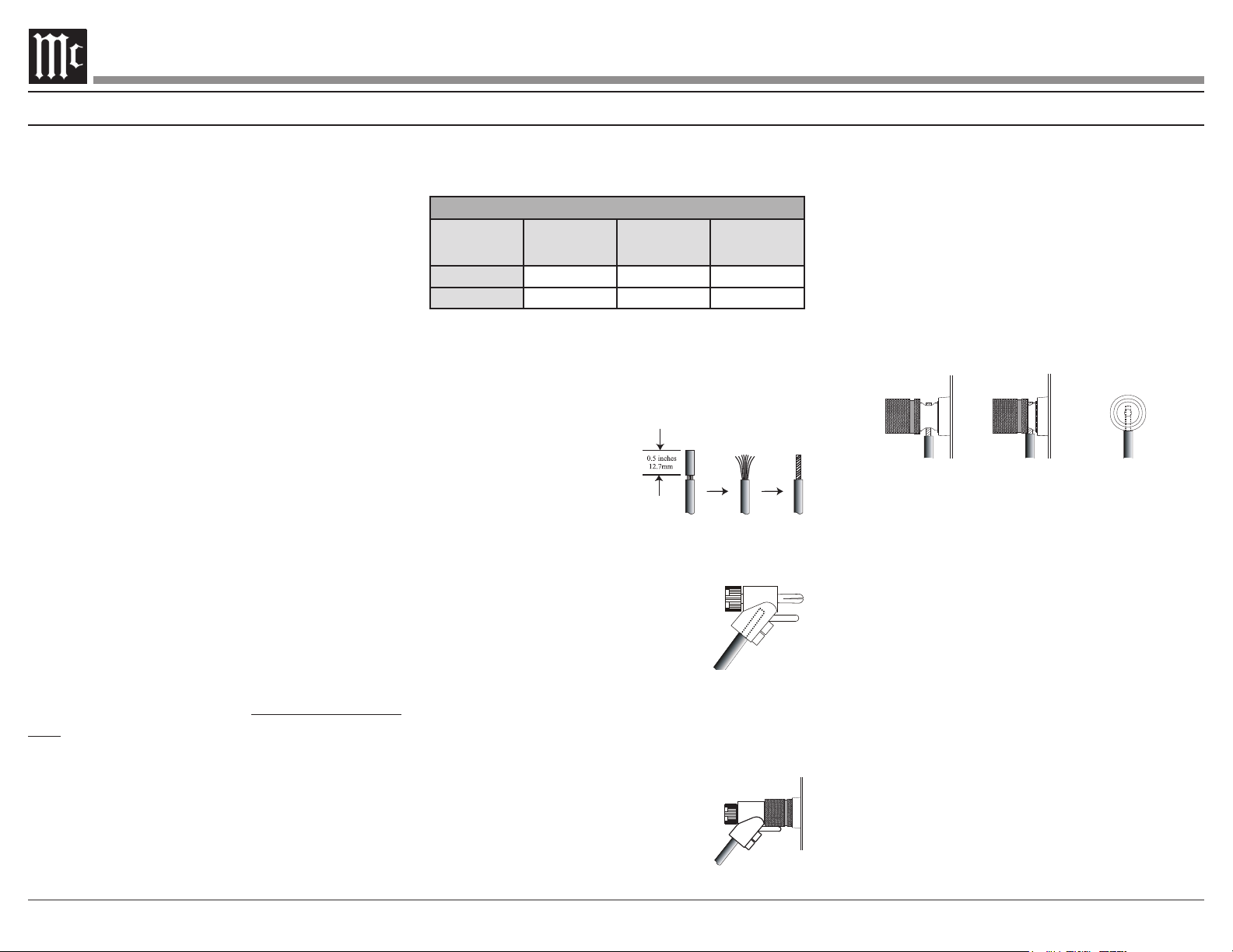
Loudspeaker Cable Distance vs Wire Gauge Guide
Loudspeaker
Impedance
25 feet
(7.62 meters)
or less
50 feet
(15.24 meters)
or less
100 feet
(30.48 meters)
or less
4 Ohms
14AWG 12AWG 10AWG
8 Ohms
16AWG 14AWG 12AWG
3. Prepare the Loudspeaker Hookup Cable for
Bare wire cable ends:
4.
cable ends. If the cable is
stranded, twist the strands
together as tightly as
Note: 1. If desired, the twisted
ends can be soldered to keep the strands together.
2. The prepared bare wire cable ends may also be
inserted into spade lug connectors.
5. Attach the previously prepared bare
wire cable ends into the banana
plugs and secure the connections.
Note: Banana plugs are for use in the United States and
Canada only.
6.
hookup cables with banana plugs into the hole at
the end of the MI502 Negative and
Positive Output Terminals, making
sure to match up channel designation
with Loudspeaker location.
How to Connect in a Multi Channel System
Figure 7
Figure 8
Figure 6
7. Connect the Loudspeaker hookup cables to the
MI502 Output Terminal being careful to observe
the correct polarities, making sure to match up
channel designation with Loudspeaker location.
8. Insert the spade lug connector or prepared
section of the cable end into the terminal side
access hole. Then tighten the terminal cap until
so the lugs or wire cannot slip out. Refer to
WARNING: Loudspeaker terminals are hazardous
live and present a risk of electric shock.
For additional instruction on making
Loudspeaker Connections contact your
McIntosh Dealer or McIntosh Technical
Support.
9. Connect the MI502 power cord to an active AC
outlet.
Figure 9
Figure 10
Fig ure 11
Caution: Do not connect the AC Power Cord
to the MI502 Rear Panel until after the
Loudspeaker Connections are made. Failure
to observe this could result in Electric Shock.
The connection instructions below, provide an
example of a typical Multi-channel System. Your
system may vary from this, however the actual
components would be connected in a similar man-
ner. For additional information refer to “Connec-
tor and Cable Information” on page 3.
1. For Remote Power Control, connect a power
CNTRL Power Control INput.
Note: When the Power Control Cable is connected
between the MI502 and an A/V Control Center
or pre-amplifier, the AUTO OFF Signal Sensing
Circuitry is automatically disabled.
2.
MI502 BALanced INPUTS.
Note: The MI502 UNBALanced Inputs may be used in place
of the Balanced Inputs when the A/V Control Center
or pre-amplifier has Unbalanced Output Connections
instead of Balanced Connections.
designed for Loudspeakers with an impedance of
4 ohms or 8 ohms. Connect a single Loudspeaker
only to the Channel Output Terminals.
When connecting Loudspeakers to the MI502 it
is very important to use cables of adequate size,
so there is little to no power loss in the cables.
Loading ...
Loading ...
Loading ...