McIntosh Laboratory, Inc. 2 Chambers Street Binghamton, New York 13903-2699 Phone: 607-723-3512 www.mcintoshlabs.com
MI502
Two Channel
Power Amplifier
Owner’s Manual
2
General Information
1. The MI502 mutes the speaker output for approxi-
2. Included with the MI502 are two Side Rack
Mounted Brackets and screw fasteners. Refer to
page 5 for installing the Side Rack Mount Brackets.
3. For the best performance and safety it is important
to always attach a single Loudspeaker with an 8
Ohm or 4 Ohm impedance to the Right or Left
Channel output terminals. Refer to “How to
Connect” on page 8.
Note: The impedance of a Loudspeaker actually varies as
the Loudspeaker reproduces different frequencies.
As a result, the nominal impedance rating of the
Loudspeaker (usually measured at a midrange
frequency) might not always agree with the imped-
ance of the Loudspeaker at low frequencies where
the greatest amount of power is required. Contact the
Loudspeaker Manufacturer for additional informa-
tion about the actual impedance of the Loudspeaker
before connecting it to the McIntosh MI502.
4. In the event the MI502 Channel(s) over heat, due to
improper ventilation or Loudspeaker Impedance,
the protection circuits will activate. The Front
Panel Channel LED will change color and the audio
will be muted. Refer to page 9. When the MI502
has returned to a safe operating temperature,
Channel(s) normal operation will resume.
5. For additional information on the MI502 and
other McIntosh Products please visit the McIntosh
Website at www.mcintoshlabs.com.
Copyright 2022 © by McIntosh Laboratory, Inc.
Important Safety Information is supplied in a separate document “Important Additional Operation Information Guide”
Table of Contents including Figures
Introduction � � � � � � � � � � � � � � � � � � � � � � � � � � � � � 2
General Information � � � � � � � � � � � � � � � � � � � � � � 2
Connector and Cable Information � � � � � � � � � � � 3
Performance Features� � � � � � � � � � � � � � � � � � � � � � 3
Installation � � � � � � � � � � � � � � � � � � � � � � � � � � � � � � 4
Dimensions � � � � � � � � � � � � � � � � � � � � � � � � � � � � � � 4
Output Terminals � � � � � � � � � � � � � � � � � � � � � � � � � 5
Figures 1 - 5 . . . . . . . . . . . . . . . . . . . . . . . . . . . . 5
Front Panel Displays� � � � � � � � � � � � � � � � � � � � � � � 6
Rear Panel Connections � � � � � � � � � � � � � � � � � � � � 7
How to Connect Multi Channel System � � � � � � � 8
Figures 6 - 11 . . . . . . . . . . . . . . . . . . . . . . . . . . . 8
How to Operate � � � � � � � � � � � � � � � � � � � � � � � � � � 9
Figures 12 & 13 . . . . . . . . . . . . . . . . . . . . . . . . . 9
Specifications � � � � � � � � � � � � � � � � � � � � � � � � � � � 10
Packing Instructions � � � � � � � � � � � � � � � � � � � � � 11
Thank You from all of us at McIntosh
You have invested in a precision instrument that
will provide you with many years of enjoyment.
Please take a few moments to familiarize yourself
with the features and instructions to get the
maximum performance from your equipment.
If you need further technical assistance, please
contact your dealer who may be more familiar with
your particular setup including other brands. You
can also contact McIntosh with additional questions
or in the unlikely event of needing service.
McIntosh Laboratory, Inc�
2 Chambers Street
Binghamton, New York 13903
Technical Assistance (607) 723-3512
Fax (607) 724-0549
Customer Service (607) 723-3515
Fax (607) 723-1917
Email support@mcintoshlabs.com
Website www.mcintoshlabs.com
Please Take A Moment
For future reference, you can write down your
serial number and purchase information here. We
can identify your purchase from this information
if the occasion should arise:
Serial Number: __________________________
Purchase Date: ___________________________
Dealer Name: ___________________________
POWE R
MI5 02
2 C HANN EL
PO WER AMPL IFI ER
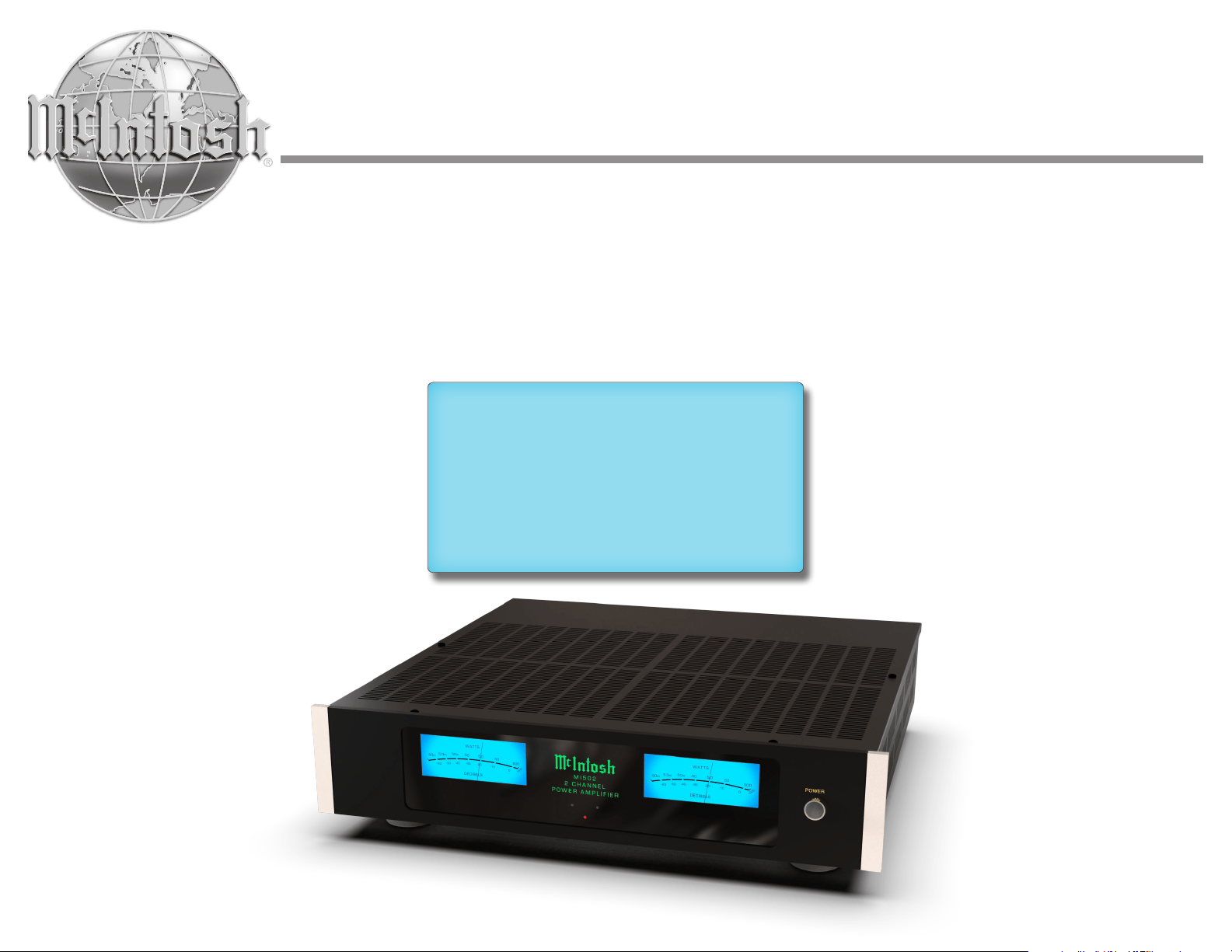
MI 502 with side mount brackets
Introduction
Now you can take advantage of traditional
McIntosh standards of excellence in the MI502
produces high power output per channel and will
drive quality Loudspeakers to a high level of
performance. The MI502 reproduction is sonically
transparent and absolutely accurate. The McIntosh
Sound is “The Sound of the Music Itself.”
3
Connector and Cable Information
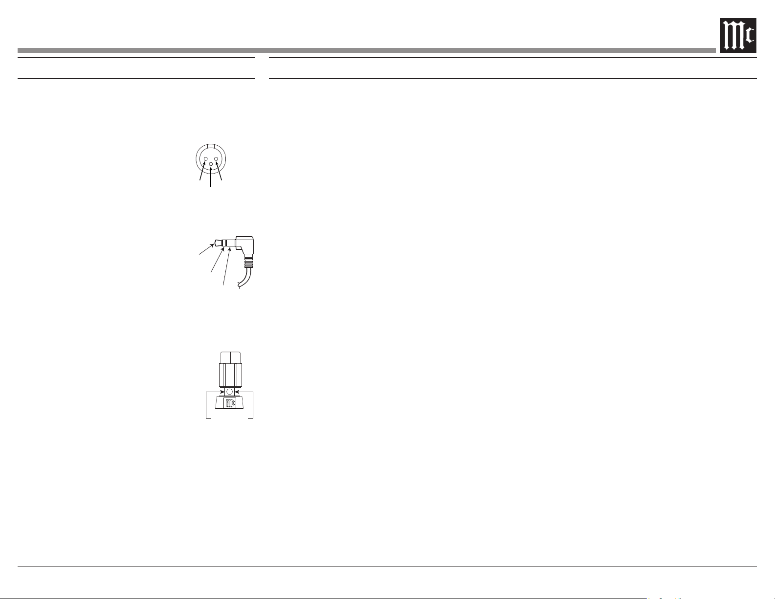
XLR Connectors
Balanced Input, Input/Output Connectors on the
MI502. Refer to the diagram for connection:
PIN 1: Shield/Ground
PIN 2: + Input/Output
PIN 3: - Input/Output
Power Control Connector
The MI502 Power Control Input receives an
Control Output will in turn
provide a +12 volt Output Signal
with a total current up to 50mA.
An additional connection is for
controlling the illumination of
the MI502 Meter Power Output Indicators. The
3.5mm stereo mini phone plug connects to a
Power Control Output.
Output Terminal Connector
When cables with spade lugs are
used for Loudspeaker Connection,
the spade lugs need an opening of at
least 3/10 inch (7.6mm)
Power
Control
Meter
Illumination
Control
Ground
3/10 of an inch
(7.6millimeters)
• Power Output
Channels, each capable of 500 watts into 8
ohms 800 watts into 4 ohms Loudspeakers with
distortion less than 0.05%.
• Loudspeaker Guard
The McIntosh Loudspeaker Guard Circuit
into clipping, with its harsh distorted sound that
can damage your valuable Loudspeakers.
• Balanced and Unbalanced Inputs
There are Balanced and Unbalanced
Channels.
• Sentry Monitor and Thermal Protection
McIntosh Sentry Monitor power output stage
protection circuits ensure the MI502 will have
a long and trouble free operating life. Built-in
Thermal Protection circuits guard against
overheating.
• Illuminated Power Meters
The Illuminated Power Output Watt Meters on
the MI502 are peak responding, and indicates
• Power Control
The McIntosh Power Control Circuit allows for
• Special Power Supply
A regulated Power Supply ensures stable
noise free operation even though the power line
varies.
• LED Solid State Front Panel Illumination
The even Illumination of the Front Panel is
accomplished by extra long life Light Emitting
Diodes (LEDs). The Metal and Glass Front
Panel ensures the pristine beauty of the MI502
will be retained for many years.
Performance Features
PIN 2 PIN 1
PIN 3
4
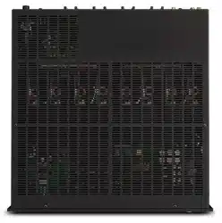
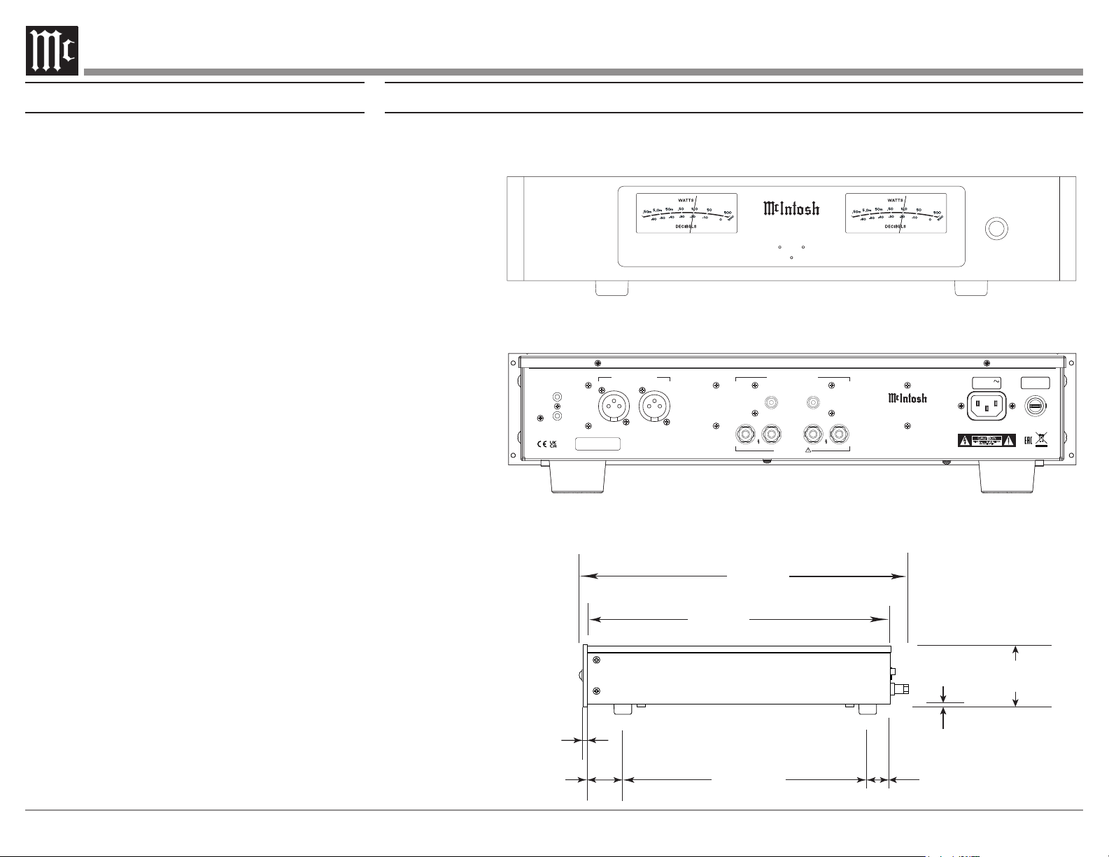
Rear View
Side View
17-1/2"
44.5cm
3-15/32"
8.8cm
4-5/16"
11.0cm
13-1/4"
33.7cm
18-1/2"
47.0cm
17-1/16"
43.3cm
.25"
.64cm
2.0"
5.0cm
13-19/32"
34.7cm
1-5/16"
3.4cm
3/16
"
.5cm
3-1/4"
8.2cm
Front View
with
Side Mount Brackets
19"
48.3cm
16-1/2"
41.9cm
SERIAL
NUMBER
CAUTION
RISK OF ELECTRIC SHOCK
DO NOT OPEN
ATTENTION:
RISQUE DE CHOC ELECTRIQUE-NE PAS OUVRIR
MI502 2 C HANNEL POWER AMPLIFIE R
McINTOSH LABORATORY, INC., BINGHAMTON, NY
HANDCRAFTED IN USA WITH US AND IMPORTED PARTS
POWER
CONTROL
IN
OUT
50/60Hz 10A
100V-240V
15AH 250V
LEFT
RIGHT
LEFTRIGHT
+
–
+
–
CLASS 2 WIRING
BALANCED INPUTS UNBALANCED INPUTS
LEFTRIGHT
OUTPUTS
Dimensions
The following dimensions can assist in determining the best location for your MI502.
Installation
The MI502 needs to be placed upright on its four
feet. It also can be custom installed. Remove the
four feet when it is custom installed and retain them
with the fastening screws for possible future use.
The required panel cutout, ventilation cutout and unit
dimensions are shown in the drawing on the right side
of this page.
It is necessary to provide adequate ventilation for
cool operation, ensuring long life for the MI502. Do
not install the MI502 above heat generating compo-
nents. When the MI502 is installed in a cabinet with
other components, use a ventilation fan to provide cool
operating temperature.
A custom cabinet installation needs to provide the
following minimum spacing for cool operation:
Allow at least 3 inches (7.6cm) above the top, 2
inches (5.08cm) below the bottom, 3 inches (7.62cm)
behind the rear panel and 2 inches (5.08cm) on each
(6.35 cm) in front of the mounting
1
panel for clearance.
Be sure to cut out a ventilation hole in the mounting
shelf according to the dimensions in the drawing.
1
When the MI502 is installed together with other McIntosh
Components, check clearances on all components
before proceeding.
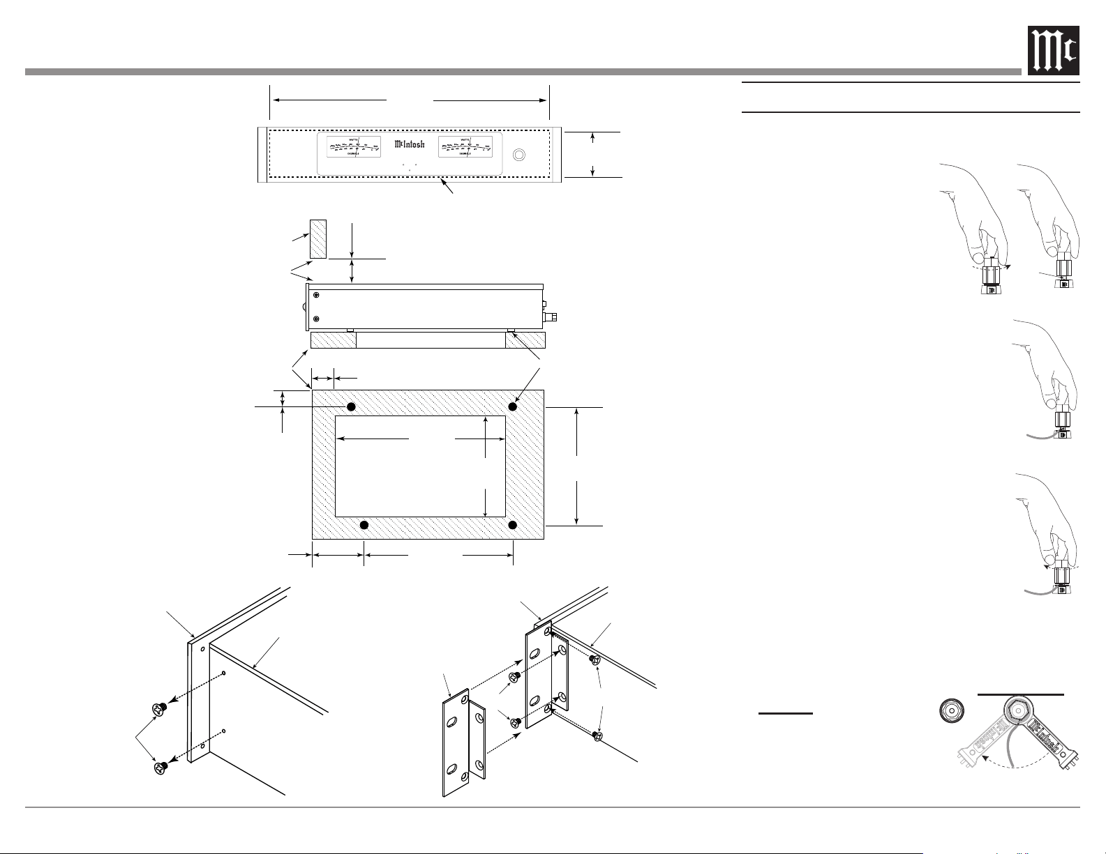
Installation of Side Rack Mount Brackets
When desired, to install MI502 Side Rack Mounting
Brackets, follow the steps below for one side at a time:
1. Refer to figure 1 to remove the two side screws
and save them for possible future use.
2. Position the Side Rack Mounting Bracket as
illustrated in figure 2. Then attach the Bracket to
the Front and Side Panel of the MI502, using the
screws supplied with the Bracket.
3. Perform steps 1 and 2 to mount the second
Bracket to the other side of the MI502.
Front View
Rear View
POW ER
MI502
2 CHANNEL
PO WER A MPL IFI ER
Side View
5
Cutout Opening for Custom Mounting
Support
Shelf
Chassis
Spacers
Cabinet
Front
Panel
Opening
for Ventilation
Cutout Opening for Ventilation
16-7/8"
42.8cm
3-1/4"
8.2cm
25/32
"
2.0cm
29/32
"
2.4cm
3"
7.6cm
11-19/32"
29.7cm
15"
38.1cm
Cutout Opening
for Ventilation
10-9/16"
26.9cm
14-7/16"
36.2cm
3"
7.6cm
Remove two
Screws from
the Chassis
Sidewall
and save
them
Front Panel
Side Panel
Side Rack
Mounting
Bracket
Supplied
Screws
Supplied
Screws
Front Panel
Side Panel
POWE R
MI50 2
2 CHANN EL
POW ER AMPLI FIE R
MI502 Front Panel
Custom Cabinet Cutout
MI502 Side View in
Custom Cabinet
MI502 Bottom View in
Custom Cabinet
Note: Center the cutout horizon-
tally on the unit. For clarity,
illustration not drawn to scale.
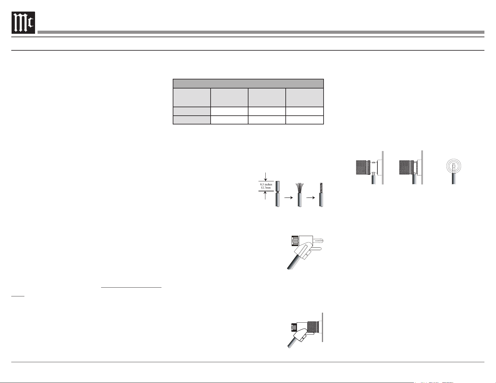
Output Terminals
When connecting the Loudspeaker Hookup
please follow the steps
below:
1. Rotate the top of the
Output Terminal Post
counterclockwise until an
opening appears. Refer to
2. Insert the Loudspeaker
hookup cable into the Output
Terminal Post opening or the cable
spade lug around the center post of
3.
3. Rotate the top of the Output Terminal
4. Place the supplied McIntosh Wrench over
the top of the Output Terminal and rotate
it one quarter of a turn (90°) to secure the
Loudspeaker Cable Connection. Do not over
tighten�
Figure 1
Opening
Figure 2
Figure 3
Figure 4
Figure 5
6
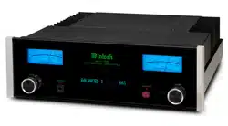
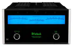
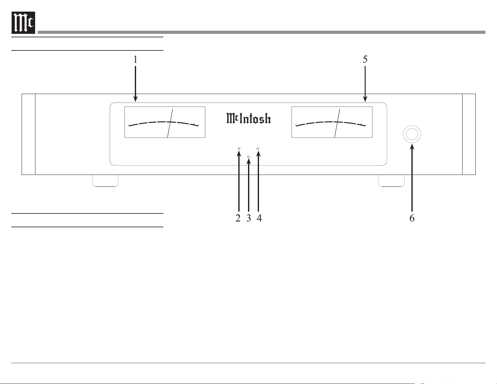
Front Panel Displays and Switch
1. Meter indicates Left Channel
2. LED indicates various Left Channel Circuitry
Functions
3. LED Standby Power On Indicator
4. LED indicates various Right Channel Circuitry
Functions
5. Meter indicates Right Channel
6. POWER Push-Button switches AC Power
M I 5 0 2
2 C H A N N E L
P O W E R A M P L I F I E R
POWER
DD EE CC II BB EE LL SS
WWAA TT TT SS
50
50 0
5.0
.50
5.0
50
-50
-30
-40
-20
-10
0
20 0 0
10 0 0
m
m
DD EE CC II BB EE LL SS
WWAA TT TT SS
50
50 0
5.0
.50
5.0
50
-50
-30
-40
-20
-10
0
20 0 0
10 0 0
m
m
Front Panel Displays
7
SERIAL
NUMBER
CAUTION
RISK OF ELECTRIC SHOCK
DO NOT OPEN
ATTENTION:
RISQUE DE CHOC ELECTRIQUE-NE PAS OUVRIR
MI502 2 CHANNEL POWER AMPLIFIER
McINTOSH LABORATORY, INC., BINGHAMTON, NY
HANDCRAFTED IN USA WITH US AND IMPORTED PARTS
POWER
CONTROL
IN
OUT
50/60Hz 10A
100V-240V
15AH 250V
LEFT
RIGHT
LEFTRIGHT
+
–
+
–
CLASS 2 WIRING
BALANCED INPUTS UNBALANCED INPUTS
LEFTRIGHT
OUTPUTS
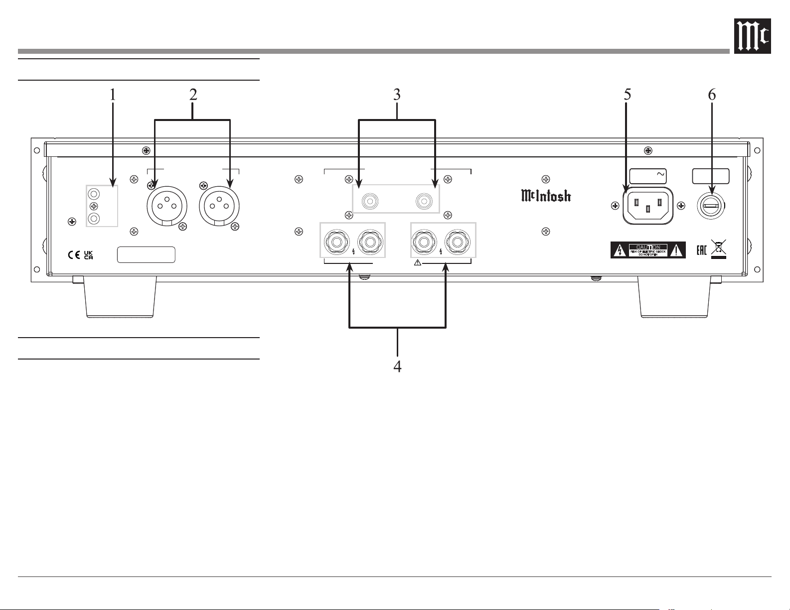
Rear Panel Connections and Switches
1.
signal from another McIntosh component
signal to another McIntosh component
2. BALANCED input RIGHT Channel
BALANCED input LEFT Channel
3. UNBALANCED input RIGHT Channel
UNBALANCED input LEFT Channel
4. Left and Right channel loudspeaker connections
5. Connect MI502 Power Cord to an AC Outlet
6. Main Fuse, refer to the rear panel for the correct
fuse size and rating
Rear Panel Connections
8
(American Wire Gauge). The smaller the Gauge
number, the larger the wire size:
Loudspeaker Cable Distance vs Wire Gauge Guide
Loudspeaker
Impedance
25 feet
(7.62 meters)
or less
50 feet
(15.24 meters)
or less
100 feet
(30.48 meters)
or less
4 Ohms
14AWG 12AWG 10AWG
8 Ohms
16AWG 14AWG 12AWG
3. Prepare the Loudspeaker Hookup Cable for
Bare wire cable ends:
4.
cable ends. If the cable is
stranded, twist the strands
together as tightly as
Note: 1. If desired, the twisted
ends can be soldered to keep the strands together.
2. The prepared bare wire cable ends may also be
inserted into spade lug connectors.
5. Attach the previously prepared bare
wire cable ends into the banana
plugs and secure the connections.
Note: Banana plugs are for use in the United States and
Canada only.
6.
hookup cables with banana plugs into the hole at
the end of the MI502 Negative and
Positive Output Terminals, making
sure to match up channel designation
with Loudspeaker location.
How to Connect in a Multi Channel System
Figure 7
Figure 8
Figure 6
7. Connect the Loudspeaker hookup cables to the
MI502 Output Terminal being careful to observe
the correct polarities, making sure to match up
channel designation with Loudspeaker location.
8. Insert the spade lug connector or prepared
section of the cable end into the terminal side
access hole. Then tighten the terminal cap until
so the lugs or wire cannot slip out. Refer to
WARNING: Loudspeaker terminals are hazardous
live and present a risk of electric shock.
For additional instruction on making
Loudspeaker Connections contact your
McIntosh Dealer or McIntosh Technical
Support.
9. Connect the MI502 power cord to an active AC
outlet.
Figure 9
Figure 10
Fig ure 11
Caution: Do not connect the AC Power Cord
to the MI502 Rear Panel until after the
Loudspeaker Connections are made. Failure
to observe this could result in Electric Shock.
The connection instructions below, provide an
example of a typical Multi-channel System. Your
system may vary from this, however the actual
components would be connected in a similar man-
ner. For additional information refer to “Connec-
tor and Cable Information” on page 3.
1. For Remote Power Control, connect a power
CNTRL Power Control INput.
Note: When the Power Control Cable is connected
between the MI502 and an A/V Control Center
or pre-amplifier, the AUTO OFF Signal Sensing
Circuitry is automatically disabled.
2.
MI502 BALanced INPUTS.
Note: The MI502 UNBALanced Inputs may be used in place
of the Balanced Inputs when the A/V Control Center
or pre-amplifier has Unbalanced Output Connections
instead of Balanced Connections.
designed for Loudspeakers with an impedance of
4 ohms or 8 ohms. Connect a single Loudspeaker
only to the Channel Output Terminals.
When connecting Loudspeakers to the MI502 it
is very important to use cables of adequate size,
so there is little to no power loss in the cables.
9
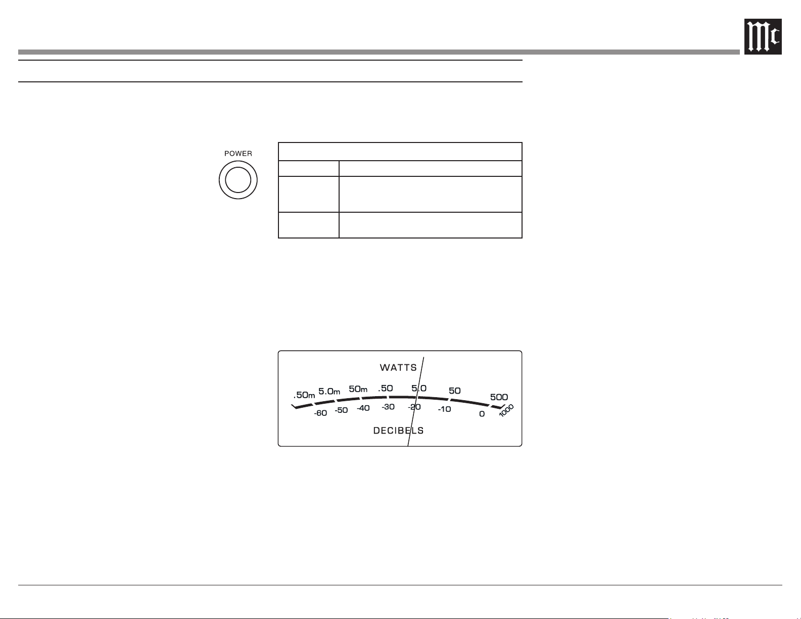
Power On
The LED STANDBY/ON Indicator illuminates to
indicate the MI502 is connected to AC Power. To
switch ON the MI502, press the POWER button on
the Front Panel or switch On the Audio
Source Component providing there is a
Power Control Cable Connection to the
Notes: 1. It will take about 6 seconds for the
MI502 to complete the initialization of
the internal circuitry when switched On.
2. There must be a power control connection between
the MI502 and the Audio Source Component in order
for the Remote Control Operation Power ON/OFF to
function.
3. When the MI502 is receiving a Power Control
ON Signal, the Front Panel POWER Push-Button
becomes inactive.
Auto O Function
The MI502 incorporates Power Save Circuitry to
automatically place the MI502 into the power saving
Standby Mode approximately 30 minutes after there
has been an absence of an audio input signal on both
channels.
When there is a Power Control Connection
Component, the AUTO OFF Function is bypassed.
Channel Operational Indication
The MI502 Front Panel has two LEDs. The LEDs
indicate the current functioning status for each of
the two channels.
MI502 Channel Operation Functions
LED COLOR
Functional Status
Amber
Indicates when maximum Power Output for the
Channel has occured with prevention of Audio
Clipping
Red
Indicates current limit or short circuit for the
Channel Loudspeaker Output Connection
Power Output Meters
The MI502 Power Output Meters indicate the
13. The meters respond to all the musical informa-
to an accuracy of at least 95% of the power output
with only a single cycle of a 2,000Hz tone burst.
How to Operate
Figure 12
Fig ure 13

10
Specications
Wide Band Damping Factor
Greater than 85 8 ohm Load
Greater than 45 4 ohm Load
Input Impedance
32,000 ohms Balanced
18,000 ohms Unbalanced
Voltage Gain
28dB
Power Control Input
Power Control Output
Power Requirements
50-60Hz at 15 Amps
Standby: less than 0.5 watt
Overall Dimensions
Width is 17-1/2 inches (44.5cm)
Width with side mount brackets is 19 inches (48.3cm)
Height is 4-5/16 inches (11.0cm) including feet
Depth is 21 inches (53.3cm) including the Front
Panel and Cables
Weight
21.5 pounds (9.8 kg) net, 37.9 pounds (17.2 kg)
in shipping carton
Shipping Carton Dimensions
Width is 26-1/2 inches (67.3cm)
Height is 11-3/4 inches (29.9cm)
Depth is 24-1/4 inches (61.6cm)
Power Output
Minimum sine wave continuous average power
output per channel, both channels operating is:
500 watts into a 8 ohm load
800 watts into a 4 ohm load
Output Load Impedance
8 and 4 ohms
Rated Power Band
20Hz to 20,000Hz
Total Harmonic Distortion
0.05% maximum harmonic distortion at any power
level from 250 milliwatts to rated power,
20Hz to 20,000Hz
Dynamic Headroom
2.7dB, 8 ohm load 3.7dB, 4 ohm load
Frequency Response
+0, -0.9dB from 20Hz to 20,000Hz
Input Sensitivity for rated output (8 ohm load)
Input Sensitivity for rated output (4 ohm load)
Signal To Noise Ratio (A-Weighted)
81dB (98dB below rated output)
Intermodulation Distortion
0.1% maximum, if the instantaneous peak power
output does not exceed the rated power output
for any combination of frequencies from 20Hz to
20,000Hz.
11
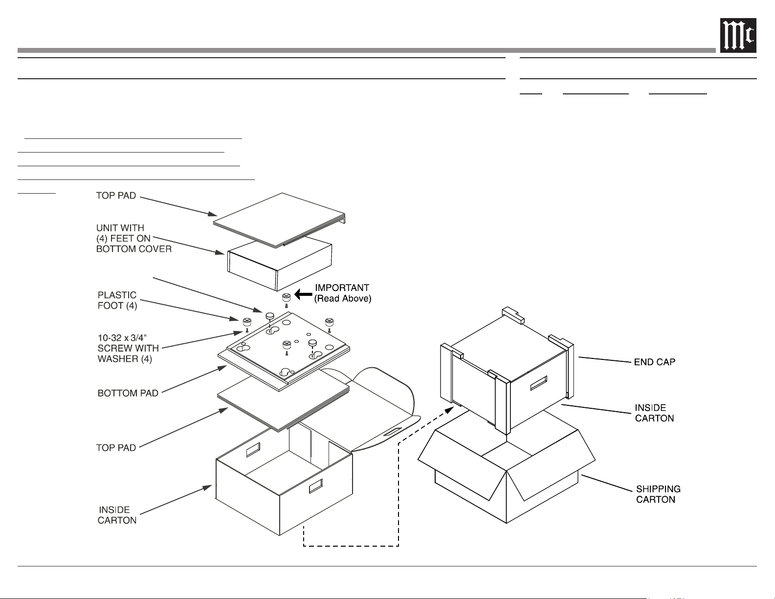
Packing Instructions Part List
Qty Part Number Description
1 033838 Shipping carton only
2 034669 End cap
1 033836 Inside carton only
2 033725 Top pad
1 034576 Bottom pad
4 017937 Plastic foot
4 400159 #10-32 x 3/4” screw
4 404080 #10 Flat washer
FOAM PLUG
In the event it is necessary to repack the equipment
for shipment, the equipment must be packed exactly
as shown below.
It is very important that the four plastic feet are
attached to the bottom of the equipment. This
will ensure the proper equipment location on the
bottom pad. Failure to do this will result in shipping
damage.
Use the original shipping carton and interior parts
only if they are all in good serviceable condition.
If a shipping carton or any of the interior part(s)
are needed, please call or write Customer Service
Department of McIntosh Laboratory. Refer to
page 2. Please see the Part List for the correct part
numbers.

The continuous improvement of its products is the
policy of McIntosh Laboratory Incorporated who
reserve the right to improve design without notice.
Printed in the U.S.A.
McIntosh Laboratory, Inc.
2 Chambers Street
Binghamton, NY 13903
www.mcintoshlabs.com
McIntosh Part No. 24119700