PRO.FORM
MILLENNIUM DRIVE"
Model No. 831.297990
Serial No.
Findthe sedal number inthe location
shownbelow. Writethe serialnumber
inthe space above for reference.
HELPLINEI
1-800-736-6879
USER'S MANUAL
SEARS, ROEBUCK AND CO., HOFFMAN ESTATES, IL 60179
TABLE OF CONTENTS
IMPORTANT PRECAUTIONS ................................................................. 3
BEFORE YOU BEGIN ....................................................................... 5
ASSEMBLY ............................................................................... 6
OPERATION AND ADJUSTMENT ............................................................. 7
HOW TO FOLD AND MOVE THE TREADMILL .................................................. 15
MAINTENANCE AND TROUBLE-SHOOTING ................................................... 17
CONDITIONING GUIDELINES ............................................................... 19
PART LIST ............................................................................... 22
ORDERING REPLACEMENT PARTS .................................................. Back Cover
FULL 90-DAY WARRANTY ........................................................... Back Cover
Note: An EXPLODED DRAWING is attached in the center of this manual.
2
IMPORTANT PRECAUTIONS
3
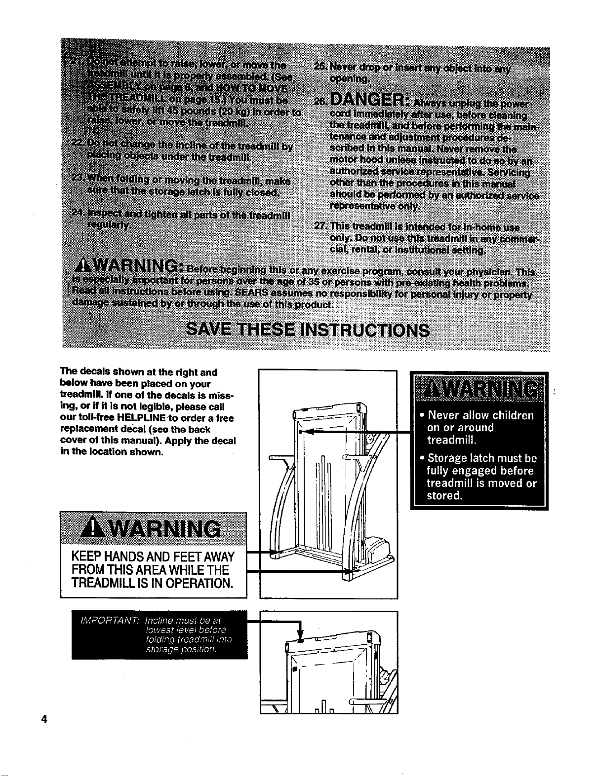
The decals shown at the right and
below have been placed on your
treadmill. If one of the decals is miss-
ing, or if it Is not legible, please call
our toll-free HELPLINE to order a free
replacement decal (see the back
cover of this manual). Apply the decal
in the location shown.
KEEPHANDSANDFEETAWAY
FROMTHISAREAWHILETHE
TREADMILLIS INOPERATION.
4
BEFORE YOU BEGIN
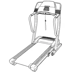
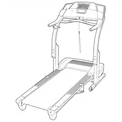
Thank you for selecting the new PROFORIVP J81i
treadmill. The J81itreadmill combines advanced tech-
nologywith innovativedesign to let you enjoyan excel-
lent form of cardiovascularexercise inthe convenience
and privacyof yourhome. And when you're not exer-
cising,the uniqueJ81ican be folded up, requiringless
than half the floor space ofother treadmills.
For your benefit, read this manual carefully before
using the treadmill. If you have additional questions,
please call our toll-free HELPLINE at 1-800-736-6879,
Monday throughSaturday, 7 a.m. until7 p.m. Central
Time (excluding holidays).To help usassist you,
please note the productmodel number and sedal num-
ber before calling.The model number of the treadmill
is831.297990. The sedal number can be found on a
decal attached to the treadmill(see the front cover of
this manual for the location).
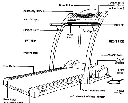
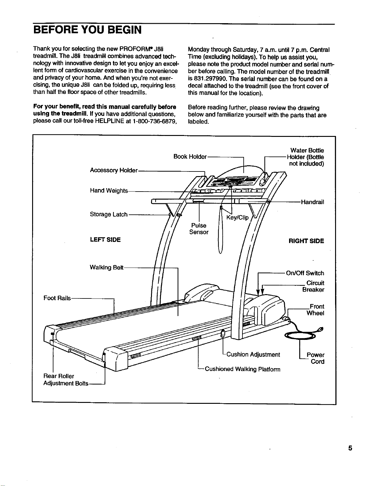
Before reading further,please review the drawing
below and familiarize yourselfwith the parts that are
labeled.
Accessory Holder
Book Holder Water BotUe
(Bottle
not included)
Hand Weights
Storage Latch
LEFT SIDE
Key/Clip
Pulse
Sensor
Handrail
RIGHT SIDE
Foot Rails
Walking Belt On/Off Switch
Circuit
Breaker
Front
Wheel
Rear Roller
Adjustment Bolts
Cushion Adjustment
Cushioned Walking Platform
Power
5
ASSEMBLY
Assembly requires two people. Set the treadmill in a cleared area and remove all packing materials. Do not
dispose of the packing materialsuntil assembly is completed. No tools are required for assembly.
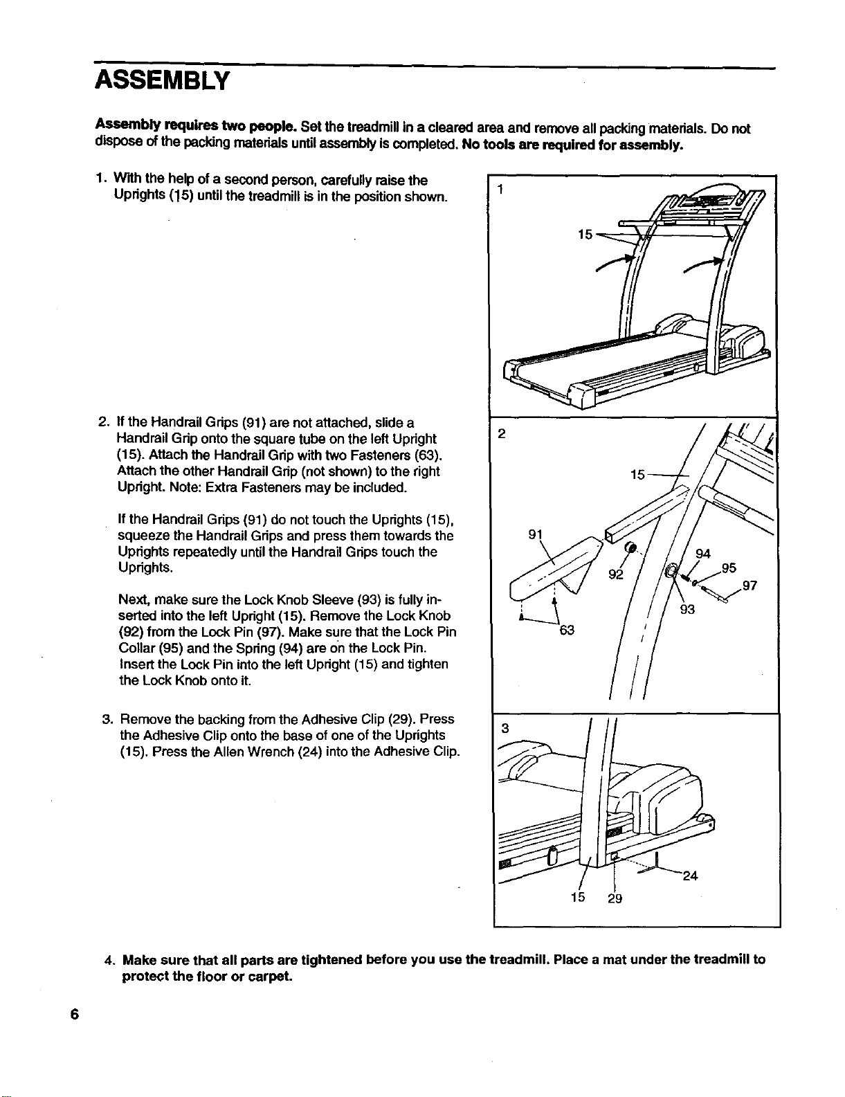
1. With the helpof a second person, carefully raise the
Uprights (15) until the treadmill is in the positionshown.
2. If the Handrail Grips (91) are not attached, slide a
Handrail Grip onto the square tube on the left Upright
(15). Attach the Handrail Gdp with two Fastenem (63).
Attach the other Handrail Grip (not shown) to the right
Updght. Note: Extra Fasteners may be included.
If the Handrail Grips (91) do not touch the Uprights (15),
squeeze the Handrail Grips and press them towards the
Uprights repeatedly untilthe Handrail Grips touch the
Uprights.
Next, make sure the Lock Knob Sleeve (93) is fully in-
serted intothe left Upright (15). Remove the Lock Knob
(92) from the Lock Pin (97). Make sure that the Lock Pin
Collar (95) and the Spring(94) are on the Lock Pin.
Insert the Lock Pin intothe left Upright (15) and tighten
the Lock Knob onto it.
3. Remove the backing from the Adhesive Clip (29). Press
the Adhesive Clip onto the base of one of the Uprights
(15). Press the Allen Wrench (24) into the Adhesive Clip.
91
3
15 29
4. Make sure that all parts are tightened before you use the treadmill. Place a mat under the treadmill to
protect the floor or carpet.
6
OPERATION AND ADJUSTMENT
THE PERFORMANT LUBETM WALKING BELT
Your treadmill features a walking belt coated with
PERFORMANT LUBETM, a high-performance lubricant.
IMPORTANT: Never apply silicone spray or other
substances to the walking belt or the walking plat,
form. Such substances will deteriorate the walking
belt and cause excessive wear.
HOW TO PLUG IN THE POWER CORD
Your treadmill, like any other type of sophisticated
electronic equipment, can be seriouslydamaged by
sudden voltage changes in your home's power.
Voltage surges, spikes, and noise interference can
result from weather conditions or from other appliances
being turned on or off. To decrease the possibility of
your treadmill being damaged, always use a surge
suppressor with your treadmill (see drawing 1 at
the right).
Surge suppressors are soldat most hardware stores
and department stores. Use only asingle-outlet surge
suppressor that is UL 1449 listed as a transient voltage
surge suppressor (TVSS). The surge suppressor must
have a UL suppressed voltage rating of 400 volts or
less and a minimum surge dissipation of 450 joules.
The surge suppressor must be electrically rated for
120 volts AC and 15 amps.
This product must be grounded. If it should malfunc-
tionor break down, groundingprovidesa path of least
resistance for electriccurrent to reduce the risk of elec-
tric shock. This productisequipped with a cordhaving
an equipment-groundingconductorand agrounding
plug. Plug the power cord into a surge suppressor,
and plug the surge suppressor into an appropriate
outlet that is properly installed and grounded in
accordance with all local codes and ordinances.
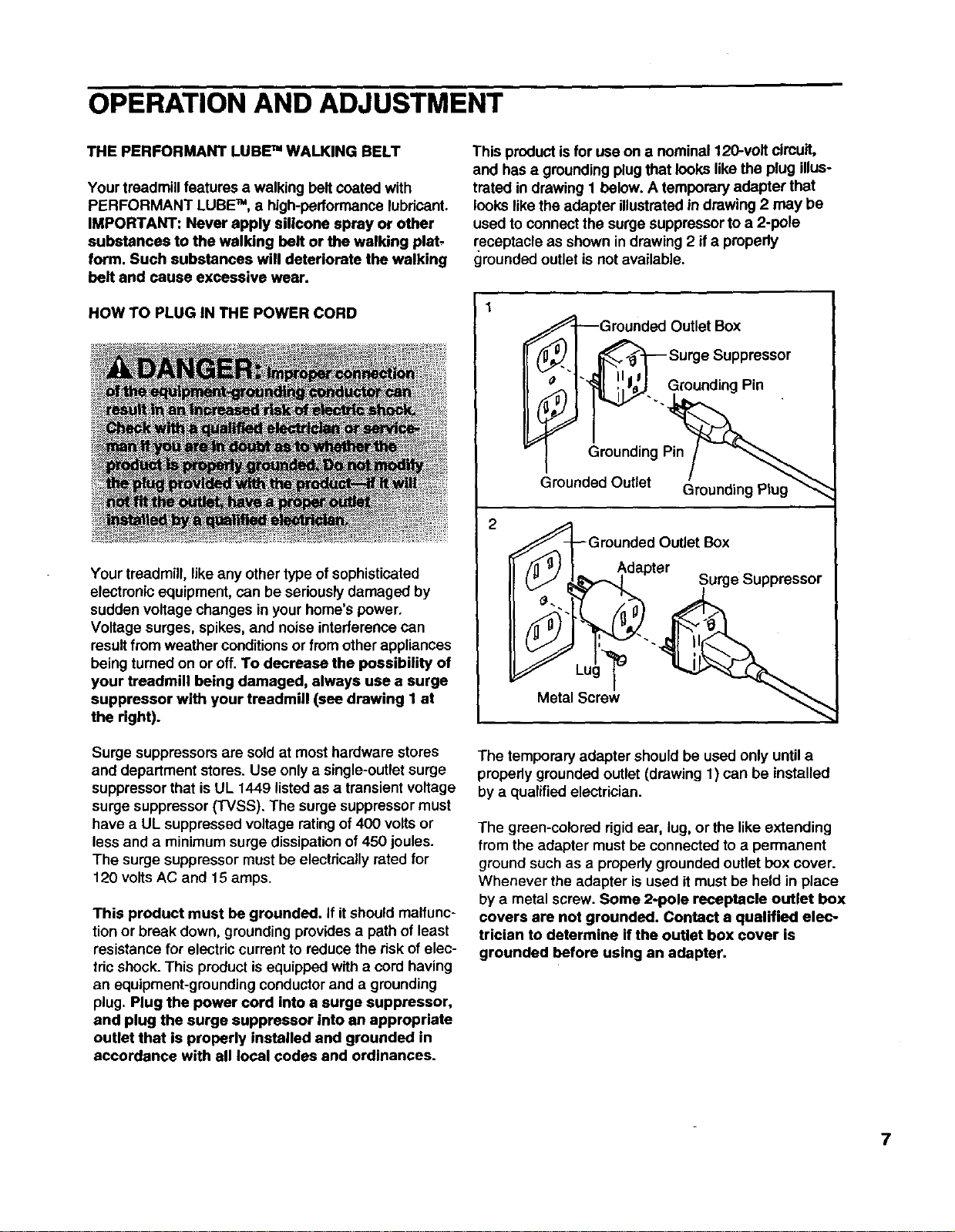
This productis for use on a nominal 120-volt circuit,
and has a groundingplugthat looks like the plug illus-
trated in drawing t below. A temporary adapter that
looks like the adapter illustrated in drawing2may be
used to connect the surge suppressorto a 2-pole
receptacle as shown in drawing 2 if apropedy
grounded outletis not available.
€_-I_Grounded Outlet Box
_'l _ Surge Suppressor
_G!n!_il p_ll_'1" _1 '!',l_'J GroundingPin
Grounded Outlet Box
Adapter ^
("J _k'%_-,_l Surge _uppressor
Metal Screw
The temporary adapter should be used only until a
properly grounded outlet (drawing 1) can be installed
by a qualified electrician.
The green-colorad rigid ear, lug, or the like extending
from the adapter must be connected toa permanent
ground such as a properlygrounded outlet box cover.
Whenever the adapter is used itmust be held in place
by a metal screw. Some 2-pole receptacle outlet box
covers are not grounded. Contact a qualified elec-
trician to determine if the outlet box cover is
grounded before using an adapter.
7
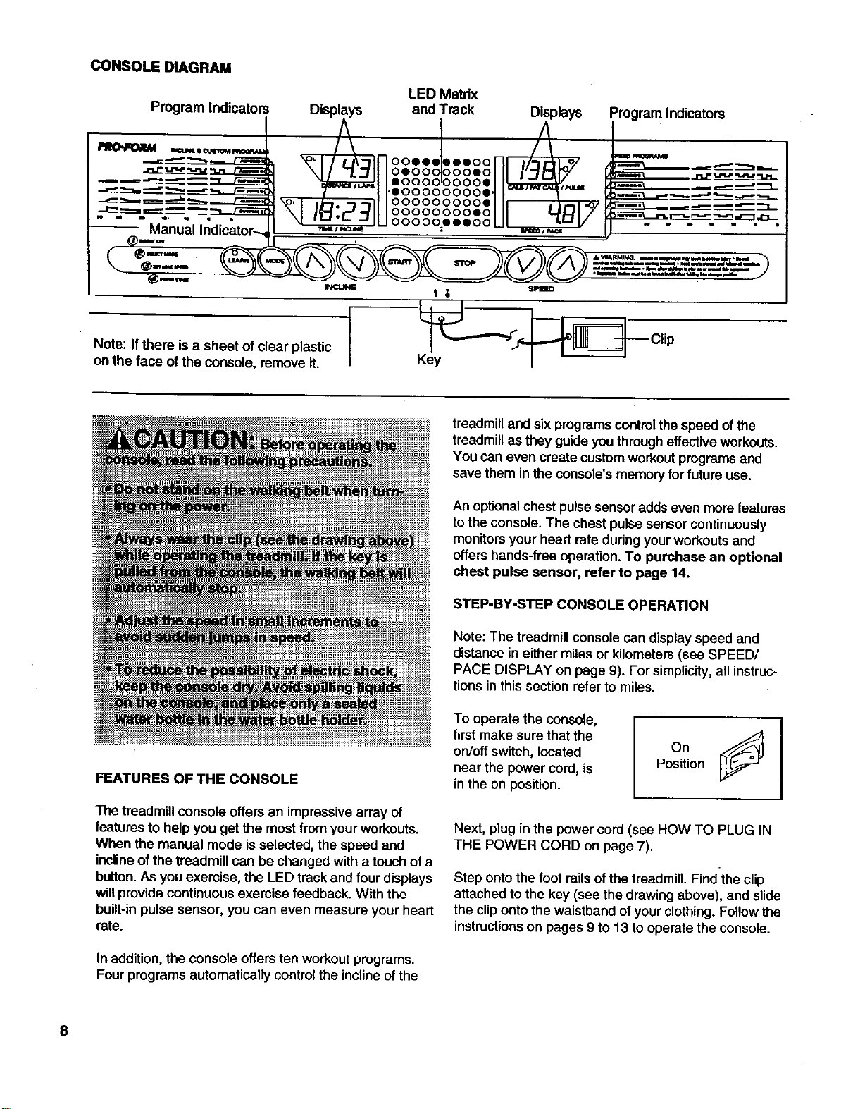
CONSOLE DIAGRAM
Program Indicatol LED Matrix
Displays and Track Displays
oooooooooe
ooooooooeo
ooooo=eeeoo
Note: Ifthere is a sheet of clear plastic
on the face of the console, remove it.
Program Indicators
__ Clip
FEATURES OF THE CONSOLE
The treadmill console offers an impressive array of
features to help you get the most from your workouts.
When the manual mode is selected, the speed and
inclineof the treadmill can be changed with a touch of a
button.As you exemise, the LED track and four displays
willprovide continuous exemise feedback. With the
buiit-inpulse sensor, you can even measure your heart
rate.
In addition,the console offers ten workoutprograms.
Four programs automatically controlthe inclineof the
treadmill and six programscontrol the speed ofthe
treadmill as they guide you througheffectiveworkouts.
You can even create custom workoutprogramsand
save them in the console's memoryfor future use.
An optionalchest pulse sensoradds even more features
to the console. The chest pulse sensor continuously
monitors your heart rate during your workouts and
offers hands-free operation. To purchase an optional
chest pulse sensor, refer to page 14.
STEP-BY-STEP CONSOLE OPERATION
Note: The treadmill console can display speed and
distance in either miles or kilometers (see SPEED/
PACE DISPLAY on page 9). For simplicity, all instruc-
tions in this section refer to miles.
To operate the console,
first make sure that the
on/off switch, located
near the power cord, is
in the on position. OnJ
Position
Next, plug in the power cord (see HOW TO PLUG IN
THE POWER CORD on page 7).
Step ontothe foot railsofthe treadmill. Find the clip
attached to the key (see the drawing above), and slide
the clipontothe waistband ofyour clothing.Followthe
instructions on pages 9 to 13 to operatethe console.
8
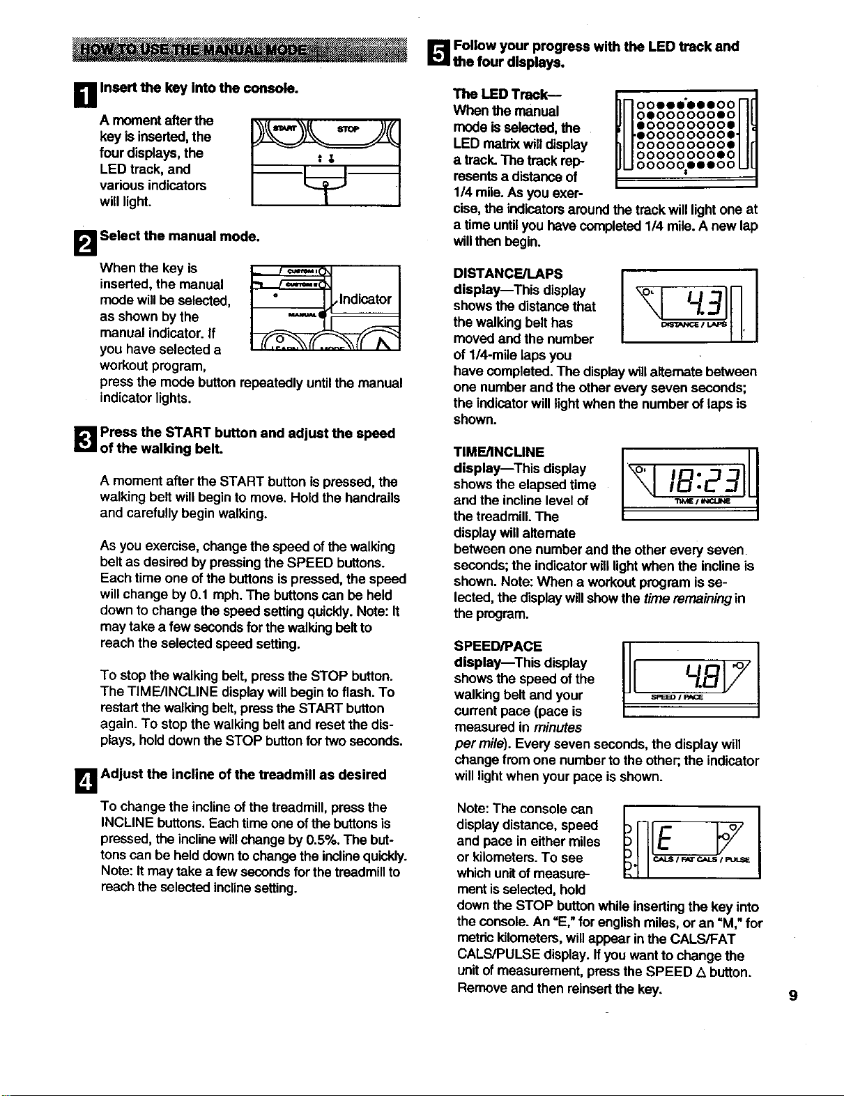
_'.'_ Follow your progress with the LED track and
the four displays.
DA moment afterthe
key is inserted,the
four displays, the
LED track, and
vadous indicators
will light.
Insert the key Into the console.
tg
B Select the manual mode.
When the key is
inserted,the manual
mode willbe selected,
as shown bythe
manual indicator, if
you have selected a
workout program,
_lndicator
press the mode button repeatedly until the manual
indicatorlights.
_! Press the START button and adjust the speed
of the walking belt.
A moment after the START button is pressed, the
walking belt will begin to move. Hold the handrails
and carefully begin walking.
As you exemise, change the speed of thewalking
belt as desired by pressingthe SPEED buttons.
Each time one ofthe buttons ispressed, the speed
will change by 0.1 mph. The buttonscan be held
downto change the speed settingquickly.Note: It
may take a few secondsfor the walkingbelt to
reach the selected speed setting.
To stop the walking belt, press the STOP button.
The TIME/INCLINE display will begin to flash. To
restartthe walking belt, press the START button
again. To stop the walking belt and resetthe dis-
plays, holddownthe STOP buttonfor two seconds.
B Adjust the incline of the treadmill as desired
To change the inclineof the treadmill, press the
INCLINE buttons.Each time one of the buttonsis
pressed, the inclinewillchange by0.5%. The but-
tonscan be held downto changethe inclinequickly.
Note: Itmay take a few secondsfor the treadmillto
reach the selected inclinesetting.
The LED Track--
When the manual
mode isselected, the
LED matrix willdisplay
a track.The track rep-
resents a distanceof
1/4 mile.As you exer-
In ooooo oooo nd
HoooooooosoHff
u.oooooooo.ul
oooooooooe
oooooooooo
O0000000SO
O000_OO000
cise, the indicators aroundthe track willlightone at
a time untilyou have completed 114mile.A new lap
willthen begin.
DISTANCE/LAPS
display--This display
shows the distance that
the walking belt has
moved and the number
of 1/4-mile laps you
have completed.The displaywillaltemate between
one number and the otherevery seven seconds;
the indicatorwill light when the number of laps is
shown.
TIME/INCLINE
display--This display
shows the elapsed time
and the incline level of
the treadmill. The
display willalternate
between one number and the other every seven
seconds; the indicator will light when the incline is
shown, Note: When a workout program is se-
lected, the display will show the time remaining in
the program.
SPEED/PACE
display--This display
shows the speed of the
walking belt and your
current pace (pace is
measured in minutes
per mile). Every seven seconds, the display will
change from one number to the other;,the indicator
willlightwhen your pace is shown.
Note: The console can
display distance, speed
and pace in either miles
or kilometers.To see
whichunitof measure-
ment isselected, hold
down the STOP buttonwhile insertingthe key into
the console. An =E,"for englishmiles, or an "M," for
metric kilometers,willappear in the CALS/FAT
CALS/PULSE display. If you want to change the
unitof measurement, pressthe SPEED L_button.
Remove and then reinsertthe key. 9
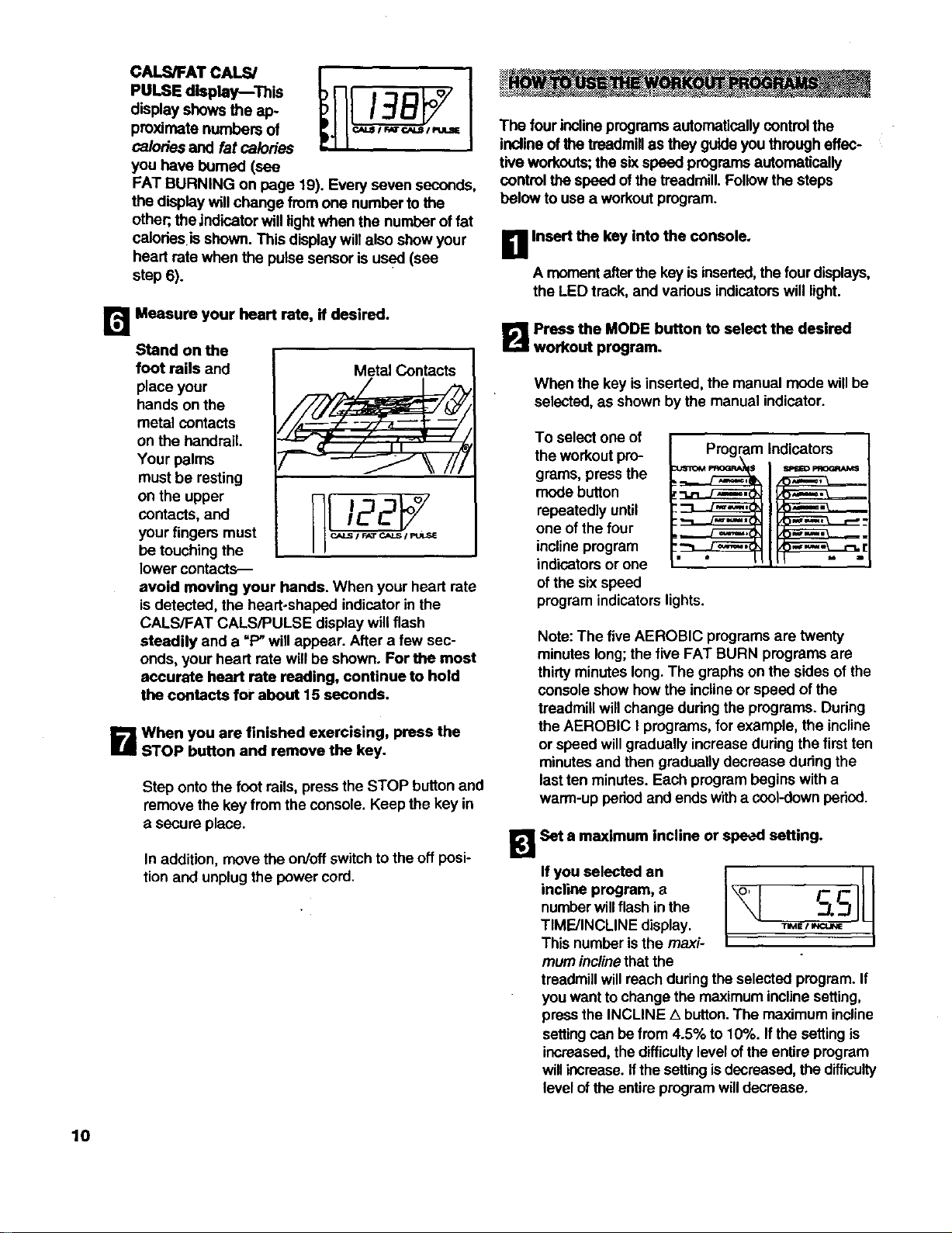
CALS/FATCALS/
PULSEdisplay This
displayshowstheap-
proximatenumbersof
calories and fat calories
you have bumed (see
FAT BURNING on page 19). Every seven seconds,
the display willchange from one number tothe
other;,the indicator will lightwhen the number of fat
calodes isshown. This display willalso show your
heart rate when the pulse sensor is used (see
step 6).
r_ Measure your heart rate, if desired.
Stand on the
foot rails and
place your
hands on the
metal contacts
on the handrail.
Your palms
must be resting
on the upper
contacts, and
your fingers must
be touching the
lower contacts--
Metal Contacts
avoid moving your hands. When your heart rate
isdetected, the heart-shaped indicator in the
CALS/FAT CALS/PULSE display will flash
steadily and a "P" willappear. After a few sec-
onds, your heart rate willbe shown. For the most
accurate heart rate reading, continue to hold
the contacts for about 15 seconds.
B When you are finished exercising, press the
STOP button and remove the key.
Step onto the foot rails, press the STOP button and
remove the key from the console. Keep the key in
asecure place.
In addition, movethe on/offswitch to theoft posi-
tion and unplug the power cord.
The four inclineprogramsautomaticallycontrolthe
inclineof the treadmillas they guide you through effec-
tive workouts;the six speed programsautomatically
controlthe speed ofthe treadmill. Followthe steps
below touse a workoutprogram.
D Insert the key into the console.
A momentafter the key isinserted,the fourdisplays,
the LED track, and various indicatorswill light.
B Press the MODE button to select the desired
workout program.
When the key is inserted, the manual mode willbe
selected,as shownby the manual indicator.
To select one of
the workoutpro- Program Indicators
modegrams,press thebutton :'_r"_" I_
repeatedly until :::3--.J_,
:_
one of the four ,_
inclineprogram :_L.L3_
indicators or one " "
of the six speed
programindicators lights.
Note:The fiveAEROBIC programs are twenty
minutes long;the five FAT BURN programs are
thirtyminutes long.The graphs on the sides of the
consoleshow how the inclineor speed ofthe
treadmillwillchange dudngthe programs. During
the AEROBIC Iprograms, for example, the incline
or speed willgradually increaseduring the first ten
minutesand then gradually decrease during the
lastten minutes. Each program begins with a
warm-up peded and ends witha cool-down period.
l_RSet s maximum incline or speed setting.
incline program, a
numberwillflash inthe
TIME/INCLINE display. _B /
This number is the maxi-
mum incline that the
treadmillwillreach during the selected program. If
you wantto change the maximum inclinesetting,
press the INCLINE Abutton.The maximum incline
settingcan be from 4.5% to 10%. Ifthe settingis
increased,thedifficulty level ofthe entire program
willincrease. Ifthe settingisdecreased,the difficulty
level ofthe entire programwilldecrease.
10
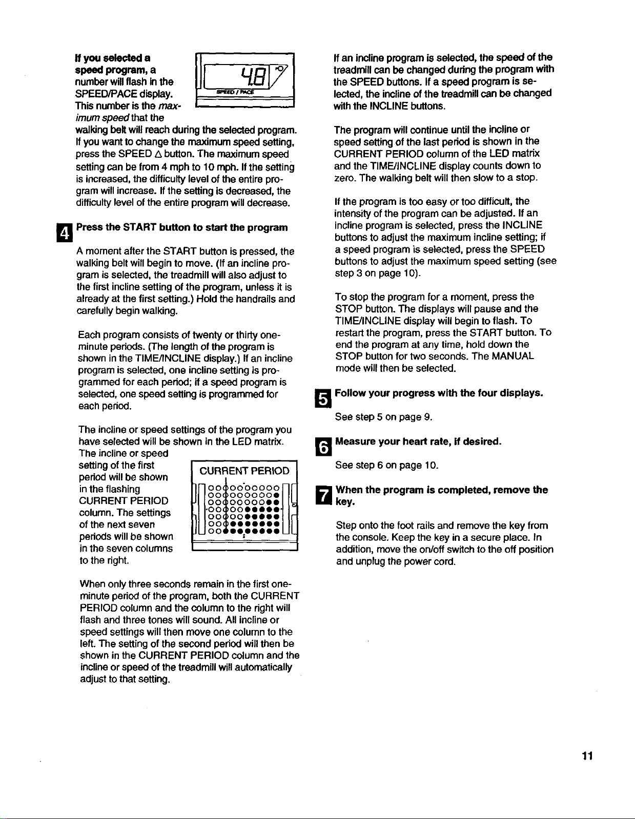
If you selected a
speed program, a
numberwillflashin the
SPEED/PACE display.
Thisnumber isthe max-
imum speed that the
walking belt willreach during the selected program.
Ifyou wantto change the maximum speed setting,
press the SPEED Z_button.The maximumspeed
settingcan be from 4 mph to 10 mph. If thesetting
isincreased,the difficultylevel of the entire pro-
gram willincrease. Ifthe settingis decreased, the
difficultylevel ofthe entire program willdecrease.
I_1 Press the START button to start the program
Amoment after the START button is pressed, the
walking belt willbegin to move. (If an inclinepro-
gram is selected, the treadmill willalso adjustto
the first inclinesetting of the program, unless it is
already at the first setting.) Hold the handrailsand
carefully beginwalking.
Each program consists oftwenty or thirty one-
minute pedods. (The lengthof the program is
shown inthe TIME/INCLINE display.) Ifan incline
programisselected, one inclinesettingis pro-
grammed for each period; ifa speed programis
selected, one speed setting is programmedfor
each period.
The inclineor speed settings ofthe programyou
have selected will be shown in the LED matrix.
The inclineor speed
setting of the first
period willbe shown
in the flashing
CURRENT PERIOD
column. The settings
of the next seven
pedods will be shown
in the seven columns
to the right.
CURRENT PERIOD
HootoooooooH
O0 O00000e
O0 oo000ee
H.ooioo.....HI
O0 ooeeeoo
O0 eooeeee
O0 eezeeSee
When onlythree seconds remain in the first one-
minute periodof the program, boththe CURRENT
PERIOD column and the column to the rightwill
flash and three tones willsound. All inclineor
speed settingswill then move one column tothe
left. The settingof the second period willthen be
shown inthe CURRENT PERIOD columnand the
inclineorspeed of thetreadmill willautomatically
adjusttothat setting.
If an inclineprogram is selected, the speed ofthe
treadmill can be changed duringthe program with
the SPEED buttons. Ifa speed program isse-
lected, the inclineof the treadmillcan be changed
withthe INCLINE buttons.
The programwill continue untilthe inclineor
speed settingof the last period isshown in the
CURRENT PERIOD column of the LED matrix
and the TIME/INCLINE display counts down to
zero. The walking belt willthen slow to astop.
If the progrem istoo easy or too difficult, the
intensityof the program can be adjusted. Ifan
inclineprogrem is selected, press the INCLINE
buttonsto adjust the maximum inclinesetting; if
aspeed programis selected, press the SPEED
buttons to adjustthe maximum speed setting (see
step 3 on page 10).
To stop the program for a moment, press the
STOP button. The displays willpause and the
TIME/INCLINE display will begin to flash. To
restart the program, press the START button. To
end the program at any time, hold down the
STOP buttonfor two seconds. The MANUAL
mode willthen be selected.
I_ Follow your progress with the four displays.
See step5 on page 9.
r_ Measure your heart rate, if desired.
See step 6 on page 10.
B When the program is completed, remove the
key.
Step ontothe foot railsand remove the key from
the console. Keep the key in a secure place. In
addition, move the on/offswitch tothe off position
and unplugthe power cord.
11
__/. * * ;*". -.:_Y+i¸¸ _i_ _-_-_._.._
The Custom 1 and Custom 2 programs are workout
programs that you create. The programs controlboth
the speed and the incline ofthe treadmill, and can be
up to 40 minutes long. The programs are stored in
memory and can be changed as many times as desired.
Followthe steps below to create a customprogram.
D Insert the key into the console.
A moment after the key is inserted,the fourdis-
plays,the LED track and variousindicatorswilllight.
B Press the MODE button to select a custom
workout program.
adjust the speed and inclineof the treadmill to the
desired levels withthe SPEED and INCLINE but-
tons. Every few timesthe SPEED buttons are
pressed, one additional indicatorwilllight or
darken in the CURRENT PERIOD column.
When the first periodis completed,three tones will
sound and the currentspeed and inclinesettings
will be stored in memory, Allsettingsshown in the
LED matrixwillthen moveone column tothe left
and thespeed settingof thesecond peded willbe
showninthe CURRENT PERIOD column.Program
speed and inclinesettingsfor the second period
as described above. Repeat this procadure until
you have programmed speed and incline settings
for as many periodsas desired. Programs can
have up to forty periods.
12
When the key is inserted, the manual mode willbe
selected, as shown bythe manual indicator.
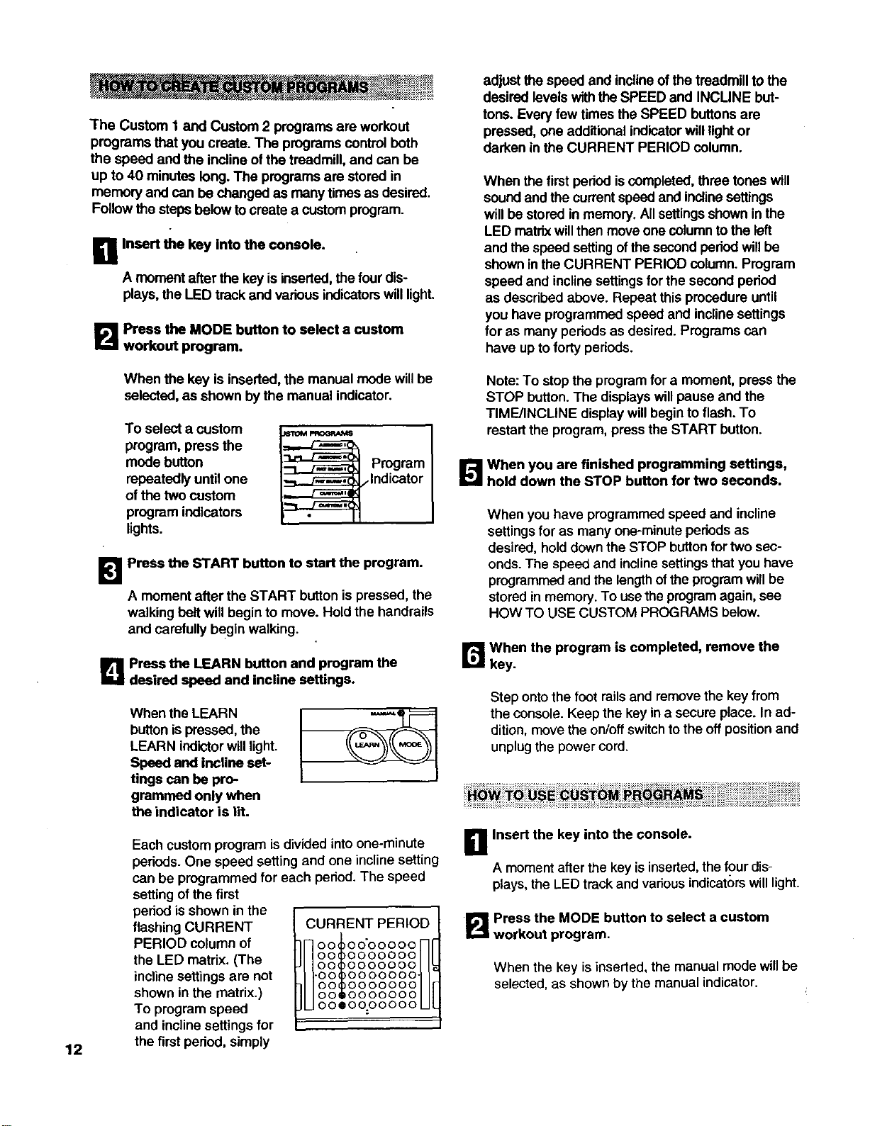
To select a custom
program, press the
mode button
repeatedly until one
of the two custom
program indicators
lights.
_ rogram
Indicator
Press the START button to start the program.
Amoment after the START button is pressed, the
walking belt will begin to move. Hold the handrails
and carefully begin walking.
_! Press the LEARN button and program the
desired speed and incline settings.
When the LEARN
buttonispressed, the
LEARN indictorwill light.
Speed and incline set-
tings can be pro-
grammed only when
the indicator is lit.
Each custom program is divided into one-minute
periods. One speed setting and one incline setting
can be programmed for each period. The speed
setting ofthe first
peded is shown in the
flashing CURRENT
PERIOD column of
the LED matrix. (The
incline settings are not
shown in the matrix.)
To program speed
and inclinesettings for
the first pedod, simply
CURRENT PERIOD
nootoooooooH!
O0 0000000
O0 0000000
H-oo oooooooNr
O0 0000000
O0 O00000O
UOOSOOOOOOOUl
Note: To stopthe progrem for a moment, press the
STOP button.The displays willpause and the
TIME/INCLINE displaywill beginto flash. To
restart the pmgrem, press the START button.
_When you are finished programming settings,
hold down the STOP button for two seconds.
When you have programmed speed and incline
settings for as many one-minuteperiods as
desired, hold downthe STOP buttonfor two sec-
onds. The speed and inclinesettingsthat you have
programmedand thelengthofthe programwillbe
stored in memory.To usethe programagain, see
HOW TO USE CUSTOM PROGRAMS below.
r_ when the program is completed, remove the
key.
Step onto the foot railsand remove the key from
the console. Keep the key ina secure place. In ad-
dition, movethe on/offswitchto the offpositionand
unplugthe power cord.
D Insert the key into the console.
Amomentafterthe key isinserted,thefour dis-
plays,the LED trackand various indicatorswilllight.
B Press the MODE button to select a custom
workout program.
When the key is inserted,the manual mode willbe
selected, as shown by the manual indicator.
To select a custom
program, press the
mode button
repeatedly until one
ofthe two custom
program indicators
lights.
mw
_rogram
Indicator
To stop the program for a moment, press the
STOP button.The displayswill pause and the
TIME/INCLINE displaywill begin to flash. To
restart the program, press the START button.To
end the program at any time, hold downthe STOP
button for two seconds. The MANUAL mode will
then be selected.
!_1 Press the START button to start the program.
A moment after the button ispressed, the walking
belt will begin to move. Hold the handrails and
carefully beginwalking.
Each program is divided intoone-minute pedods.
One speed settingand one inclinesetting are
programmed for each
period. The speed
settingof the first
period isshown in the
flashing CURRENT
PERIOD column of
the LED matrix. (The
inclinesettingsare
not shown inthe
matrix.)
CURRENT PERIOD
00_00'00000
!Neeooooo.oflF
U°°l°°°°°.-Ui
O0 O0000eo
O0 oooeeee
O0 oeeee@e
oo ee:eeeoo
L_ Follow your progress with the LED displays.
Refer to step 6 on page 11.
[]Measure your heart rate, if desired.
See step 6 on page 10.
r_When the program Is completed, remove the
key.
Step onto the foot railsand remove the key from
the console. Keep the key in a secureplace. In ad-
dition, movethe on/oftswitchtothe offpositionand
unplugthe powercord.
THE INFORMATION MODE
When onlythree seconds remain inthe first period,
both the CURRENT PERIOD column and the col-
umn to the right will flash and three tones will
sound. All speed settings will then move one col-
umn to the left. The speed setting of the second
pedod willthen be shown in the CURRENT PE-
RIOD column and the speed and incline of the
treadmill will adjust to the second settings that you
programmed previously.
The programwillcontinue untilthe speed setting
of the last period isshown in the CURRENT PE-
RIOD column of the LED matrix and the TIME/IN-
CLINE display counts down to zero. The walking
belt will then slow to astop.
During the program, the speed and inclinesettings
of the current period can be adjusted withthe
SPEED and INCLINE buttons. Adjustments will not
be stored in memory. To reprogram speed and in-
cline settings, press the LEARN button. The
LEARN indicator will light. Speed and incline set-
tings can be reprogrammed only when the indi-
cater is lit. Next, adjust the speed and inclineof
the treadmill with the SPEED and INCLINE but-
tons. When the current period of the program is
cornpleted, the new speed and incline settings will
be stored in memory. When you have repro-
grammed speed and incline settings for as many
periods as desired, press the LEARN button again.
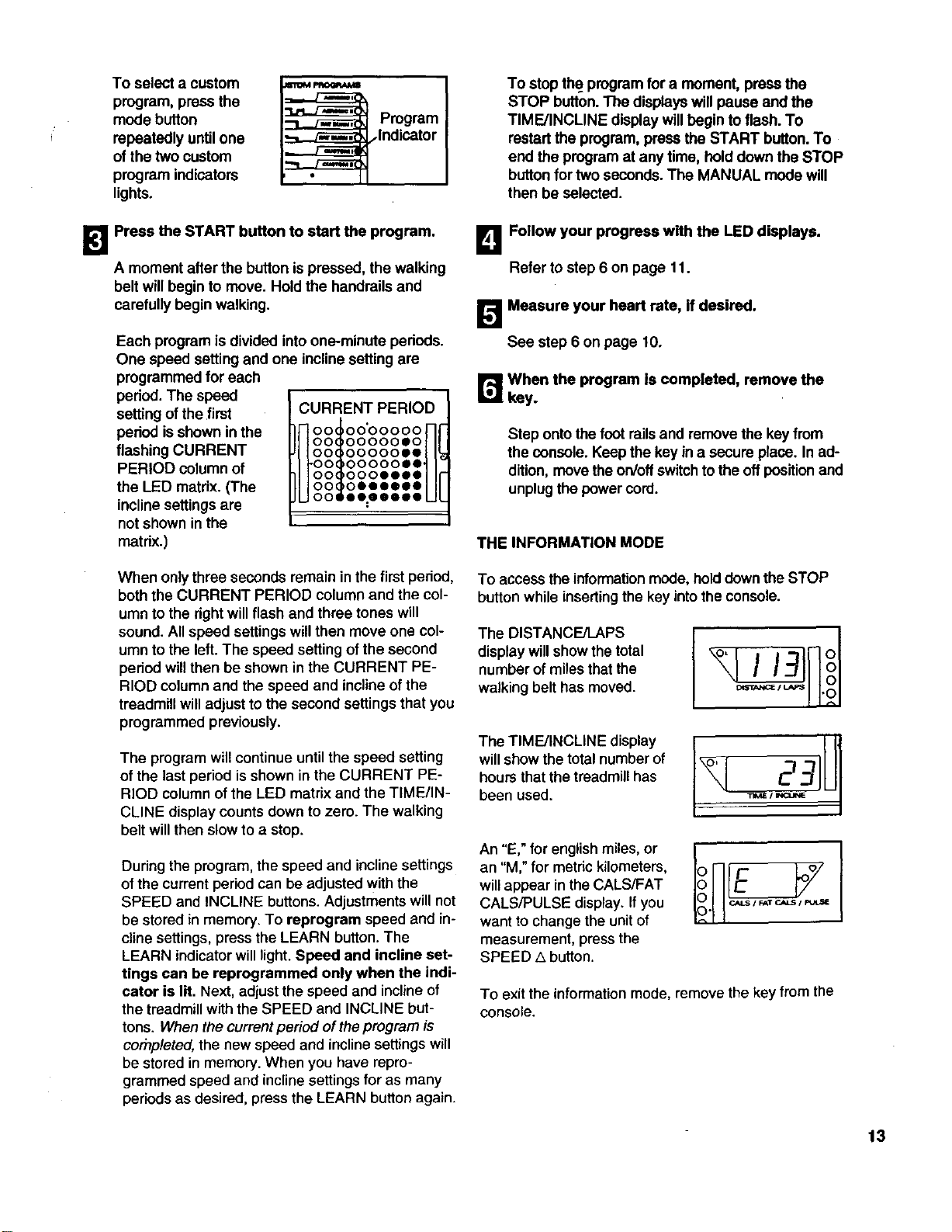
To access the informationmode, hold downthe STOP
button while insertingthe key into the console.
The DISTANCE/LAPS
display will show the total
number of miles that the
walking belt has moved.
TheTM NOL.E,is y ,U1
will show the total number of
hourS that the treadmill has
been used. _,=, --
An "E," for english miles, or
an "M," for metric kilometers,
will appear in the CALS/FAT
CALS/PULSE display. If you
want to change the unit of
measurement, press the
SPEED ,5 button.
To exit the informationmode, remove the key from the
console.
13
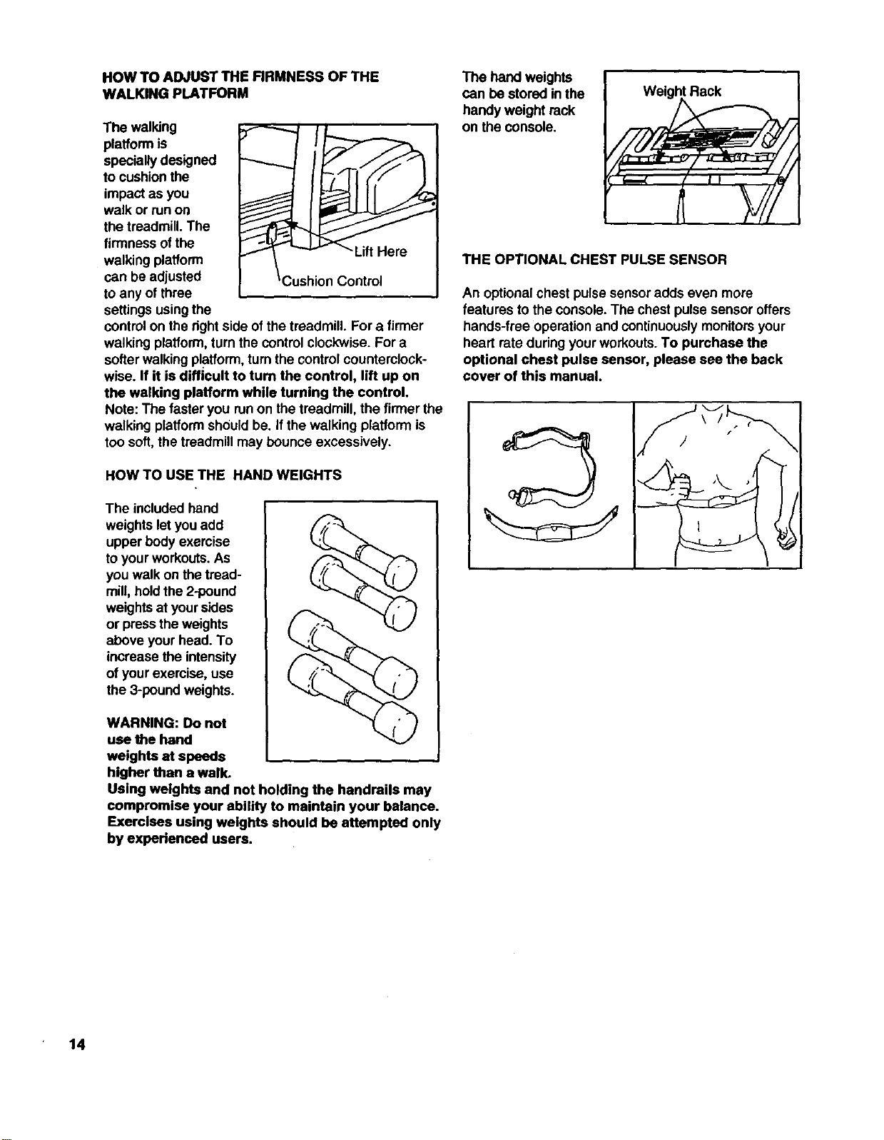
HOW TO ADJUST THE FIRMNESS OF THE
WALKING PLATFORM
The walldng
platform is
specially designed
to cushionthe
impact as you
walk or runon
the treadmill. The
firmness ofthe -Lift Hero
walking platform
can be adjusted Control
to any of three
settingsusingthe
controlon the rightside ofthe treadmill. For a firmer
walking platform,turn the control clockwise. For a
softerwalking platform,turnthe controlcounterclock-
wise. If it is difficult to turn the control, lift up on
the walking platform while turning the control.
Note: The faster you runon the treadmill, the firmer the
walking platformshould be. ifthe walking platform is
too soft,the treadmill may bounce excessively.
HOW TO USE THE HAND WEIGHTS
The included hand
weightslet you add
upper body exercise
toyour workouts.As
you walk on the troad-
mill, holdthe 2-pound
weightsat yoursides
or pressthe weights
above your head. To
increase the intensity
of yourexercise, use
the 3-poundweights.
WARNING: Do not
use the hand
weights at speeds
higher than a walk.
Using weights and not holding the handrails may
compromise your ability to maintain your balance.
Exercises using weights should be attempted only
by experienced users.
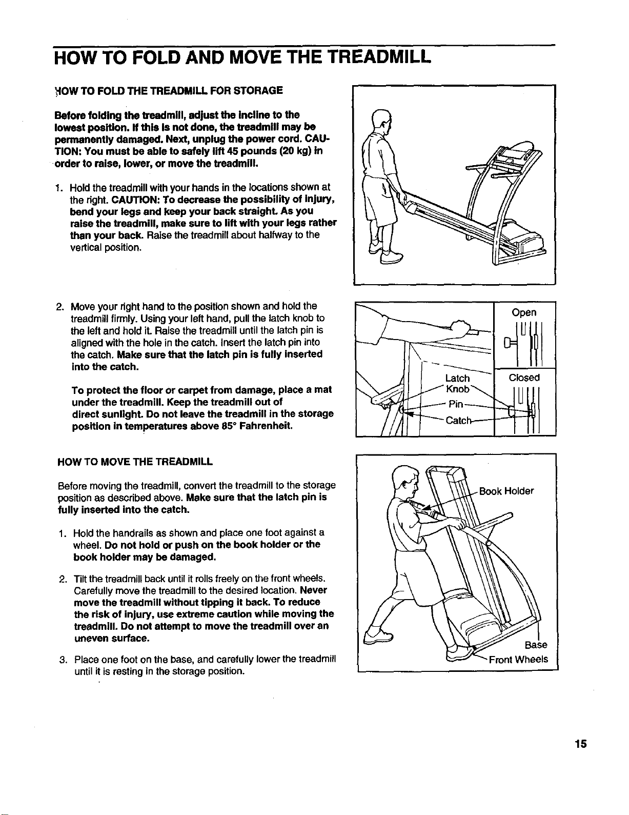
The hand weights
can be stored in the
handy weight rack
on the console.
Weight Rack
THE OPTIONAL CHEST PULSE SENSOR
An optionalchest pulse sensoradds even more
features to the console. The chestpulse sensor offers
hands-free operation and continuouslymonitorsyour
heart rate duringyour workouts.To purchase the
optional chest pulse sensor, please see the back
cover of this manual.
14
HOW TO FOLD AND MOVE THE TREADMILL
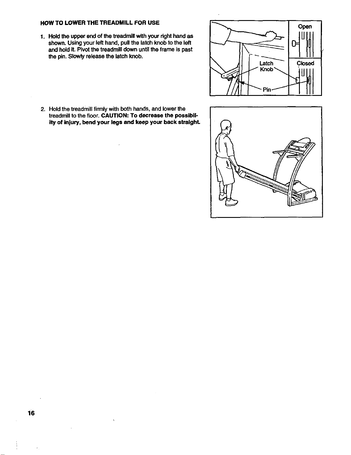
HOW TO FOLD THE TREADMILL FOR STORAGE
Before folding the treadmill, adjust the Incline to the
lowest position. If this is not done, the treadmill may be
permanently damaged. Next, unplug the power cord. CAU-
TION: You must be able to safely lift 45 pounds (20 kg) in
•order to raise, lower, or move the treadmill.
1. Hold the treadmill withyour hands in the locationsshownat
the right.CAUTION: To decrease the possibility of injury,
bend your legs and keep your back straight. As you
raise the treadmill, make sure to lift with your legs rather
than your back. Raise the treadmillabout halfway to the
vertical position.
p
2. Move your righthand to the position shown and hold the
treadmillfirmly. Using your lefthand, pullthe latch knobto
the leftand hold it. Raise the treadmill untilthe latch pinis
alignedwith the holein the catch. Insert the latch pin into
the catch. Make sure that the latch pin is fully inserted
into the catch.
To protect the floor or carpet from damage, place a mat
under the treadmill. Keep the treadmill out of
direct sunlight. Do not leave the treadmill in the storage
position in temperatures above 85° Fahrenheit.
HOW TO MOVE THE TREADMILL
Before moving the treadmill, convertthe treadmillto the storage
position as described above. Make sure that the latch pin is
fully inserted into the catch.
1. Hold the handrails as shown and place one foot against a
wheel. Do not hold or push on the book holder or the
book holder may be damaged.
2. Tiltthe treadmillback untilitrollsfreely on the front wheels.
Carefullymove the treadmillto the desired location, Never
move the treadmill without tipping it back. To reduce
the risk of injury, use extreme caution while moving the
treadmill, Do not attempt to move the treadmill over an
uneven surface.
3. Place one foot on the base, and carefully lower the treadmill
until it is resting in the storage position.
Open
Latch Closed
Knob_
Pin-----
15
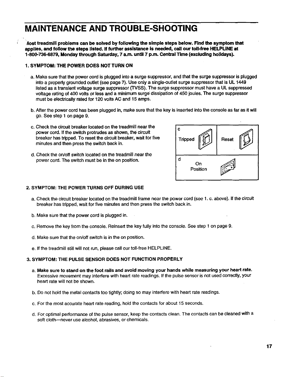
HOW TO LOWER THE TREADMILL FOR USE
1. Hold the upper end of the treadmill with your right hand as
shown. Using your lefthand, pull the latch knob to the left
and hold it. Pivot the treadmill down until the frame is past
the pin. Slowly release the latch knob.
Open
°ttl
2. Hold the treadmill firmlywith both hands, and lowerthe
treadmill to the floor. CAUTION: To decrease the possibil-
ity of injury, bend your legs and keep your back straight.
6
MAINTENANCE AND TROUBLE-SHOOTING
" Jlost treadmill problems can be solved by following the simple steps below. Find the symptom that
applies, and follow the steps listed, ff further assistance is needed, call our toll-free HELPUNE at
1-800-736-6879, Monday through Saturday, 7 a.m. until 7 p.m. Central Time (excluding holidays).
1. SYMPTOM: THE POWER DOES NOT TURN ON
a. Make sure thatthe power cord is plugged intoa surge suppressor, and that the surge suppressoris plugged
intoa prepedy groundedoutlet (see page 7). Use only a single-outlet surge suppressorthat is UL 1449
listedas a transient voltage surge suppressor (TVSS). The surge suppressor must have a UL suppressed
voltage rating of400 volts or less and a minimum surge dissipation of450 joules. The surge suppressor
must be electricallyrated for 120 volts AC and 15 amps.
b. After the power cordhas been plugged in, make sure that the key isinserted intothe console as far as itwill
go. See step 1 on page 9.
c. Check the circuitbreaker located on the treadmill near the
power cord. If the switchprotrudes as shown, the circuit
breaker has tripped. To reset the circuit breaker, wait for five
minutes and then press the switch back in.
d. Check the on/off switch located on the treadmillnear the
power cord. The switchmust be in the on position.
c
Tdpped
0j
On
Position
2. SYMPTOM: THE POWER TURNS OFF DURING USE
a. Check the circuitbreaker located on the treadmillframe near the power cord (see 1. c. above). If thecircuit
breaker has tripped,wait for five minutesand then press the switch back in.
b. Make sure that the power cord is plugged in.
c. Remove the key from the console. Reinsert the key fully intothe console. See step 1 on page 9.
d. Make sure that the on/off switch is in the on position.
e. If the treadmill still will not run, please call ourtoll-free HELPLINE.
3. SYMPTOM: THE PULSE SENSOR DOES NOT FUNCTION PROPERLY
a. Make sure to stand on the foot rails and avoid moving your hands while measuring your heart rate.
Excessive movement may interferewith hear[ rate readings. Ifthe pulse sensoris not used correctly,your
heart rate willnot be shown.
b. Do not hold the metal contacts too tightly; doing so may interfere with heart rate readings.
c. For the most accurate heart rate reading, hold the contacts for about 15 seconds.
d. For optimal performance of the pulse sensor, keep the contacts clean. The contacts can be cleaned with a
soft cloth--never use alcohol, abrasives, or chemicals.
17
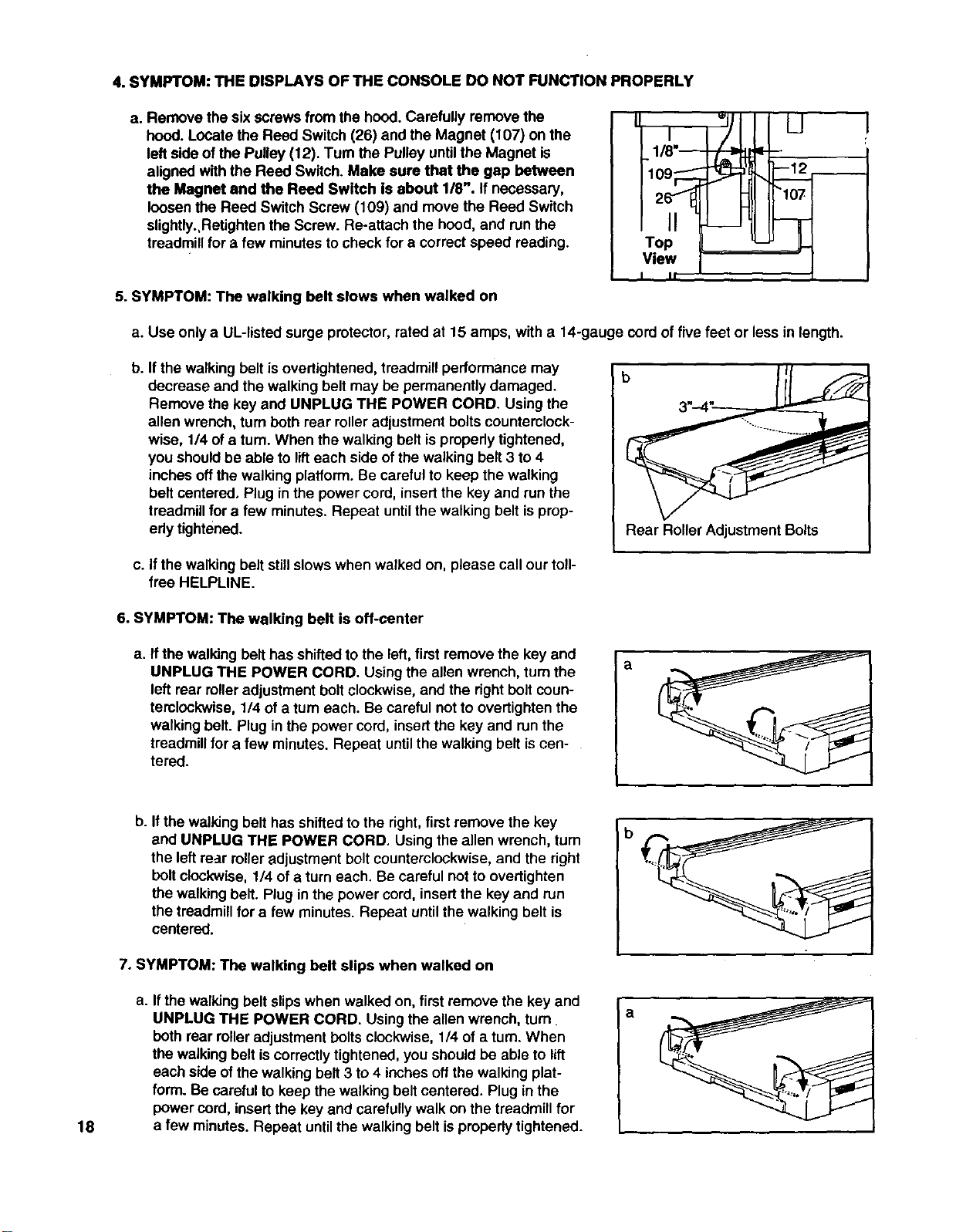
4. SYMPTOM: THE DISPLAYS OF THE CONSOLE DO NOT FUNCTION PROPERLY
a. Remove the sixscrews from the hood.Carefully remove the
hood. Locate the Reed Switch (26) and the Magnet (107) on the
leftside ofthe Pulley (12). Turn the Pulley untilthe Magnet is
aligned with the Reed Switch. Make sure that the gap between
the Magnet and the Reed Switch is about 1/8". If necessary,
loosen the Reed Switch Screw (109) and move the Reed Switch
slightly.,Retightenthe Screw. Re-attach the hood, and runthe
treadmillfor afew minutes tocheck for a correctspeed reading.
5. SYMPTOM: The walking belt slows when walked on
Iwl L_J
I It "
a. Use only a UL-listed surge protector, rated at 15 amps, with a 14-gauge cord of five feet or less in length.
b. If the walking belt isovertightened, treadmill performance may
decrease and the walking belt may be permanently damaged.
Remove the key and UNPLUG THE POWER CORD. Using the
allen wrench, turn both rear rolleradjustment boltscounterclock-
wise, 1/4 ofatum. When the walking belt is propedytightened,
you shouldbe able to lifteach side of the walking belt 3 to 4
inches offthe walking platform. Be carefulto keep the walking
belt centered, Plug in the power cord, insertthe key and run the
treadmillfor efew minutes. Repeat untilthe walking belt isprup-
edy tightened.
b
Rear Roller Adjustment Bolts
c. If the walking belt still slows when walked on, please call our toll-
free HELPLINE.
6. SYMPTOM: The walking belt is off-center
a. If the walking belt has shiftedto the left, first remove the key and
UNPLUG THE POWER CORD. Using the allen wrench, turn the
left rear roller adjustment bolt clockwise, and the dght bolt coun-
terolockwise, 1/4 of a turn each. Be careful not to overtighten the
walking belt. Plug in the power cord, insert the key and run the
treadmill for a few minutes. Repeat until the walking belt is cen-
tered.
a
18
b. Ifthe walking belt has shifted to the right, first remove the key
and UNPLUG THE POWER CORD. Using the allen wrench, turn
the left rear roller adjustment bolt counterclockwise, and the right
bolt clockwise, 1/4 of a turn each. Be careful not to overtighten
the walking belt. Plug in the power cord, insert the key and run
the treadmill for a few minutes. Repeat until the walking belt is
centered.
7. SYMPTOM: The walking belt slips when walked on
a. Ifthe walking belt slipswhen walked on, first remove the key and
UNPLUG THE POWER CORD. Using the allen wrench, turn
both rear roller adjustment bolts clockwise, 1/4 of a turn. When
the walking belt is correctly tightened, you should be able to lift
each side of the walking belt 3 to 4 inches off the walking plat-
form. Be careful to keep the walking belt centered. Plug in the
power cord, insert the key and carefully walk on the treadmill for
a few minutes. Repeat until the walking belt is properly tightened.
b
a
CONDITIONING GUIDELINES
The following guidelines will help you to plan yourex-
ercise program. Remember--these are general guide-
lines only. For more detailed exercise information, ob-
tain a reputable book or consult your physician.
EXERCISEINTENSITY
Whether your goal isto bum fat or to strengthen your
cardiovascular system, the key to achieving the
desired results is to exercise with the proper intensity.
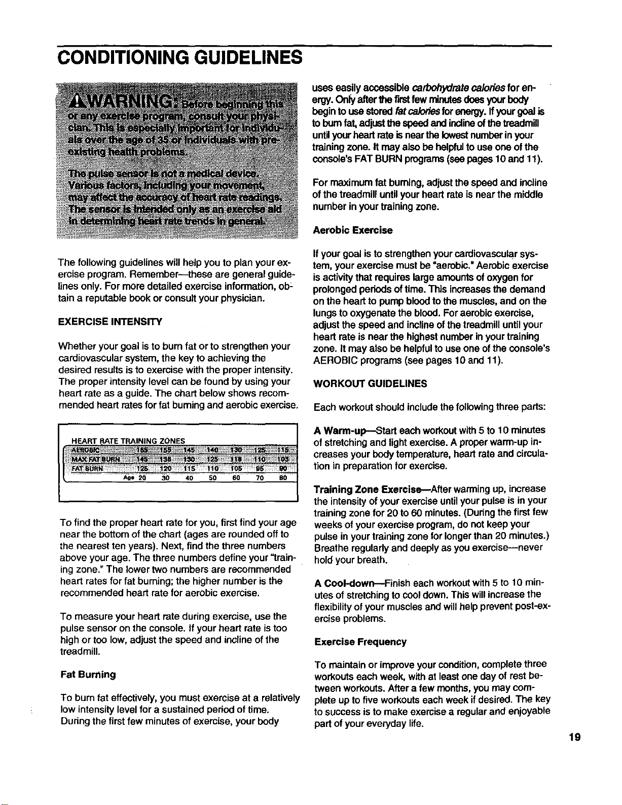
The proper intensity level can be found by using your
heart rate as a guide. The chart below shows recom-
mended heart rates for fat buming and aerobic exercise,
HEART RATETRAINING ZONES
Age 20 30 40 50 60 70 80
To findthe proper heart rate for you, first find your age
near the bottom of the chart (ages are rounded offto
the nearest ten years). Next, find the three numbers
above yourage. The three numbers define your "train-
ing zone."The lowertwo numbers are recommended
heart rates for fat burning; the highernumber isthe
recommended heart rate for aerobic exercise.
To measure your heart rate during exercise, use the
pulse sensor on the console, if your heart rate is too
high or too low, adjust the speed and incline of the
treadmill.
Fat Burning
To burn fat effectively, you must exercise at a relatively
low intensity level for a sustained period of time,
During the first few minutes of exercise, your body
uses easily accessible carbohydrate caloriesfor en-
ergy. Onlyafterthe firstfew minutesdoes yourbody
begin to use storedfat ca/odesfor energy, ffyour goal is
to bum fat,adjustthe speed and inclineofthe treadmill
untilyourheart rateisnear thelowestnumberinyour
trainingzone. It may alsobe helpfultouse one ofthe
console'sFAT BURN programs(seepages 10 and 11).
For maximum fat buming, adjustthe speed and incline
of the treadmill until your heart rate is near the middle
number in your training zone.
Aerobic Exercise
Ifyour goal isto strengthenyourcardiovascularsys-
tem, your exercise must be "aerobic." Aerobic exercise
isactivitythat requireslargeamountsof oxygen for
prolonged pedods of time. This increasesthe demand
on the heart to pump bloodto the muscles,and on the
lungsto oxygenate the blood. Foraerobic exercise,
adjust the speed and inclineof the treadmilluntilyour
heart rate is near the highestnumber in yourtraining
zone. It may also be helpfulto use one of the console's
AEROBIC programs (see pages 10 and 11).
WORKOUT GUIDELINES
Each workout should include the following three parts:
A Warm-up---Start each workoutwith 5 to 10 minutes
of stretchingand lightexercise.A properwarm-up in-
creases your bodytemperature, heart rateand circula-
tion in preparationfor exercise.
Training Zone Exercis_After warming up, increase
the intensityof your exemise untilyour pulse isin your
training zone for 20 to 60 minutes.(During thefirst few
weeks of yourexercise program,do not keep your
pulse inyour trainingzone forlongerthan 20 minutes.)
Breathe regularlyand deeplyas youexercise--never
holdyour breath.
A Cool-down---Finish each workoutwith 5to 10 min-
utes of stretchingto cooldown.This willincrease the
flexibility of yourmuscles and willhelp preventpost-ex-
ercise problems.
Exercise Frequency
To maintain or improve yourcondition,complete three
workoutseach week, with at least one day of rest be-
tween workouts.After a few months, you may com-
plete up tofive workoutseach week ifdesired. The key
to success isto make exercisea regularand enjoyable
part of youreveryday life. 19
SUGGESTED STRETCHES
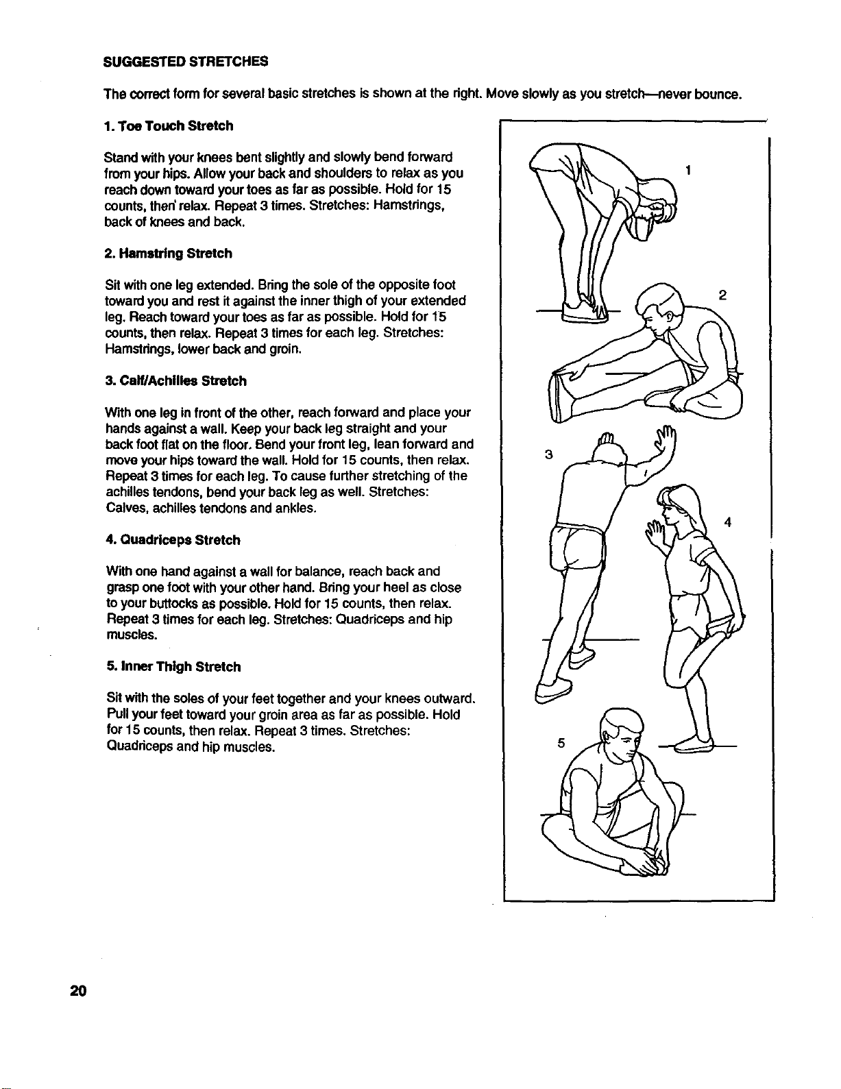
The correctform for several basic stretches is shown at the right.Move slowlyas you stretch--never bounce.
1. Toe Touch Stretch
Stand with your knees bent slightlyand slowly bend forward
from yourhips. Allow yourbackand shoulders to relax as you
roachdowntoward yourtoesas far as possible. Hold for 15
counts, then'relax. Repeat 3 times. Stretches: Hamstrings,
backof knees and back.
2. Hamstring Stretch
Sit withone leg extended. Bringthe sole ofthe opposite foot
towardyou and rest itagainst the inner thigh of your extended
leg. Reach towardyourtoes as far as possible. Hold for 15
counts,then relax. Repeat 3 timesfor each leg. Stretches:
Hamstrings,lower back and groin.
3. Calf/Achilles Stretch
With one leg infrontof the other, reach forward and place your
handsagainsta wall. Keep yourback leg straight and your
backfoot flat on the floor.Bendyour frontleg, lean forward and
moveyour hipstowardthe wall. Hold for 15 counts, then relax.
Repeat 3 times for each leg.To cause further stretchingof the
achillestendons,bend yourback leg as well. Stretches:
Calves, achillestendons and ankles.
4. Quadrlceps Stretch
With one hand againsta wall for balance, roach back and
graspone footwith yourother hand. Bringyour heel as close
toyour buttocksas possible.Hold for 15 counts, then relax.
Repeat 3 times for each leg. Stretches: Quaddceps and hip
muscles.
5. Inner Thigh Stretch
Sit withthe soles of yourfeet together and your knees outward.
Pullyourfeet toward your groinarea as far as possible. Hold
for 15 counts,then relax. Repeat 3 times. Stretches:
Quaddcepsand hip muscles.
4
2O

NOTES
21
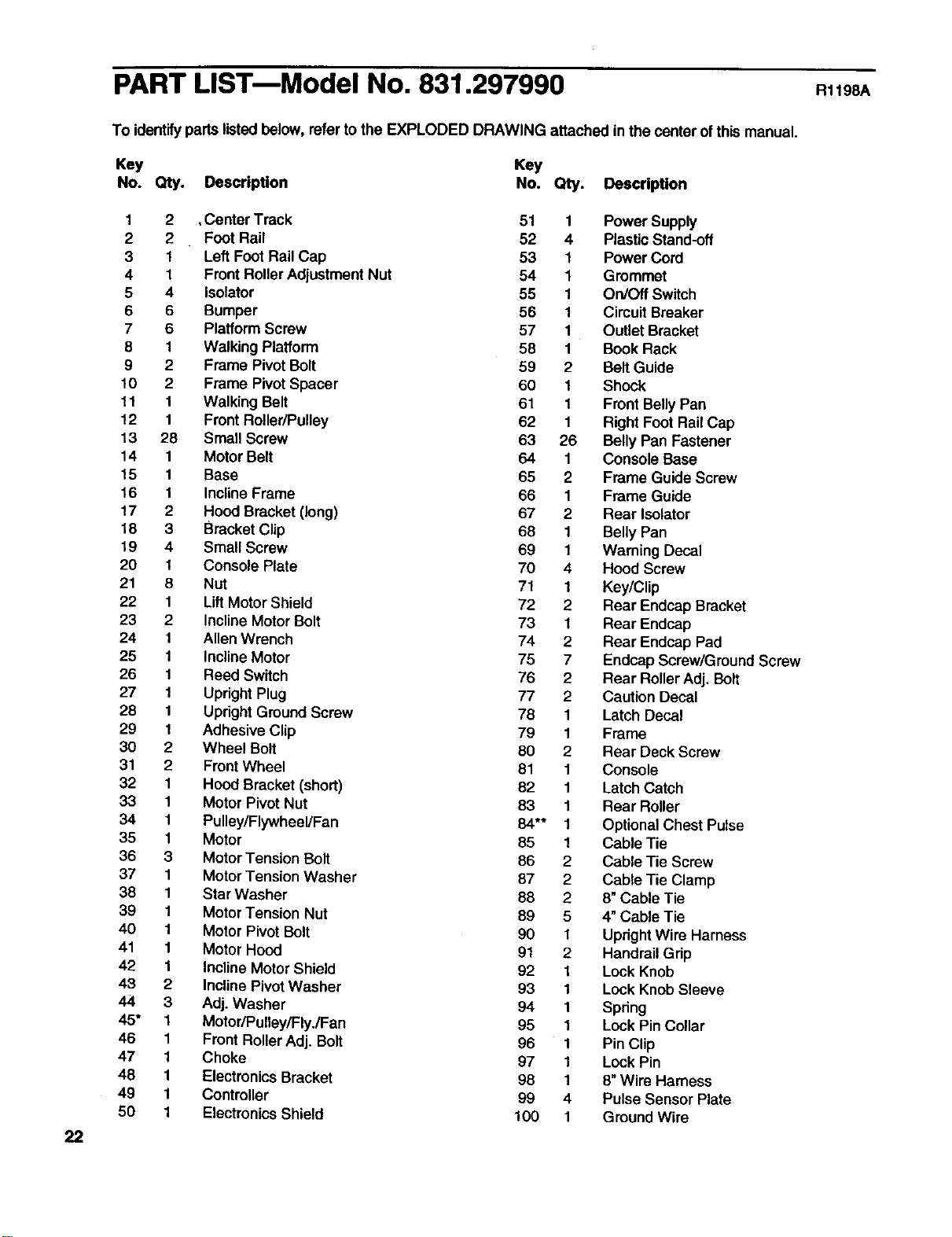
PART LISTmModel No. 831.297990 RllgBA
22
To identifyparts listedbelow, refer to the EXPLODED DRAWING attached in the centerof this manual.
Key Key
No. Qty. Description No. Qty. Description
1 2 ,Center Track 51 1
2 2 Foot Rail 52 4
31Left FootRail Cap 53 1
41Front RollerAdjustment Nut 54 1
5 4 Isolator 55 1
6 6 Bumper 56 1
7 6 Platform Screw 57 1
8 1 Walking Platform 58 1
9 2 Frame Pivot Bolt 59 2
10 2 Frame PivotSpacer 60 1
11 1 Walking Belt 61 1
12 1 Front Roller/Pulley 62 1
13 28 Small Screw 63 26
14 1Motor Belt 64 1
15 1 Base 65 2
16 1 Incline Frame 66 1
17 2 Hood Bracket (long) 67 2
18 3 Bracket Clip 68 1
19 4 Small Screw 69 1
20 1 Console Plate 70 4
21 8 Nut 71 1
22 1 Lift Motor Shield 72 2
23 2Incline Motor Bolt 73 1
24 1 Allen Wrench 74 2
25 1 InclineMotor 75 7
26 1 Reed Switch 76 2
27 1 Upright Plug 77 2
28 1 Updght GroundScrew 78 1
29 1 Adhesive Clip 79 1
30 2 Wheel Bolt 80 2
31 2 Front Wheel 81 1
32 1 Hood Bracket (short) 82 1
33 1 Motor Pivot Nut 83 1
34 1 Pulley/Flywheel/Fan 84** 1
35 1 Motor 85 1
36 3 MotorTension Bolt 86 2
37 1 Motor Tension Washer 87 2
38 1 Star Washer 88 2
39 1 Motor Tension Nut 89 5
40 1 Motor Pivot Bolt 90 1
41 1 Motor Hoed 91 2
42 1 Incline Motor Shield 92 1
43 2 Incline Pivot Washer 93 1
44 3 Adj. Washer 94 1
45* 1 Motor/Pulley/Fly./Fan 95 1
46 1 Front RollerAdj. Bolt 96 1
47 1 Choke 97 1
48 1 ElectronicsBracket 98 1
49 1 Controller 99 4
50 1 ElectronicsShield 100 1
Power Supply
Plastic Stand-off
Power Cord
Grommet
On/Off Switch
Circuit Breaker
Outlet Bracket
Book Rack
Belt Guide
Shock
Front Belly Pan
Right Feet Rail Cap
Belly Pan Fastener
Console Base
Frame Guide Screw
Frame Guide
Rear Isolator
Belly Pan
Warning Decal
Hood Screw
Key/Clip
Rear Endcap Bracket
Rear Endcap
Rear Endcap Pad
Endcap Screw/Ground Screw
Rear RollerAdj. Bolt
Caution Decal
Latch Decal
Frame
Rear Deck Screw
Console
Latch Catch
Rear Roller
OptionalChest Pulse
Cable Tie
Cable Tie Screw
Cable Tie Clamp
8"Cable Tie
4" Cable Tie
UprightWire Harness
Handrail Grip
Lock Knob
Lock Knob Sleeve
Spdng
Lock Pin Collar
Pin Clip
Lock Pin
8"Wire Harness
Pulse Sensor Plate
GroundWire
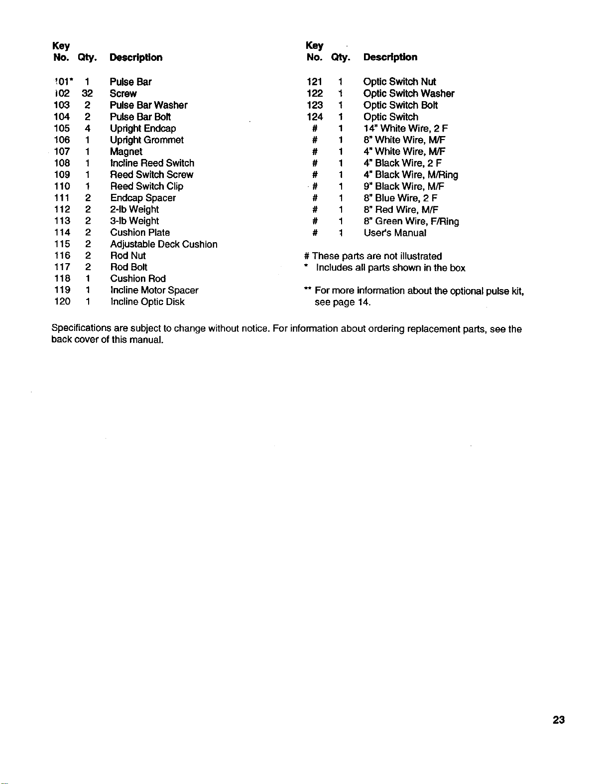
Key Key
No. Qty. Description No. Qty. Description
',01" 1 Pulse Bar 121 1 Optic Switch Nut
102 32 Screw 122 1 Optic Switch Washer
103 2Pulse Bar Washer 123 1 Optic Switch Bolt
104 2 Pulse Bar Bolt 124 1 Optic Switch
105 4 Updght Endcap # 1 14"White Wire, 2 F
106 1 Upright Grommet # 1 8"White Wire, M/F
107 1 Magnet # 1 4"White Wire, M/F
108 1 Incline Reed Switch # 1 4"Black Wire, 2 F
109 1 Reed Switch Screw # 1 4"Black Wire, M/Ring
110 1 Reed Switch Clip # 1 9"Black Wire, M/F
f 11 2 Endcap Spacer # 1 8"Blue Wire, 2 F
112 2 2-1bWeight # 1 8"Red Wire, M/F
113 2 3-1bWeight # 1 8"Green Wire, F/Ring
114 2Cushion Plate # 1 User's Manual
115 2 Adjustable Deck Cushion
116 2 Rod Nut # These parts are not illustrated
117 2 Rod Bolt * Includes all parts shown in the box
118 1 Cushion Rod
119 1 InclineMotor Spacer ** For more informationabout the optional pulsekit,
120 1 InclineOptic Disk see page 14.
Specifications are subjectto change without notice. For informationabout ordering replacement parts, see the
back cover of this manual.
23
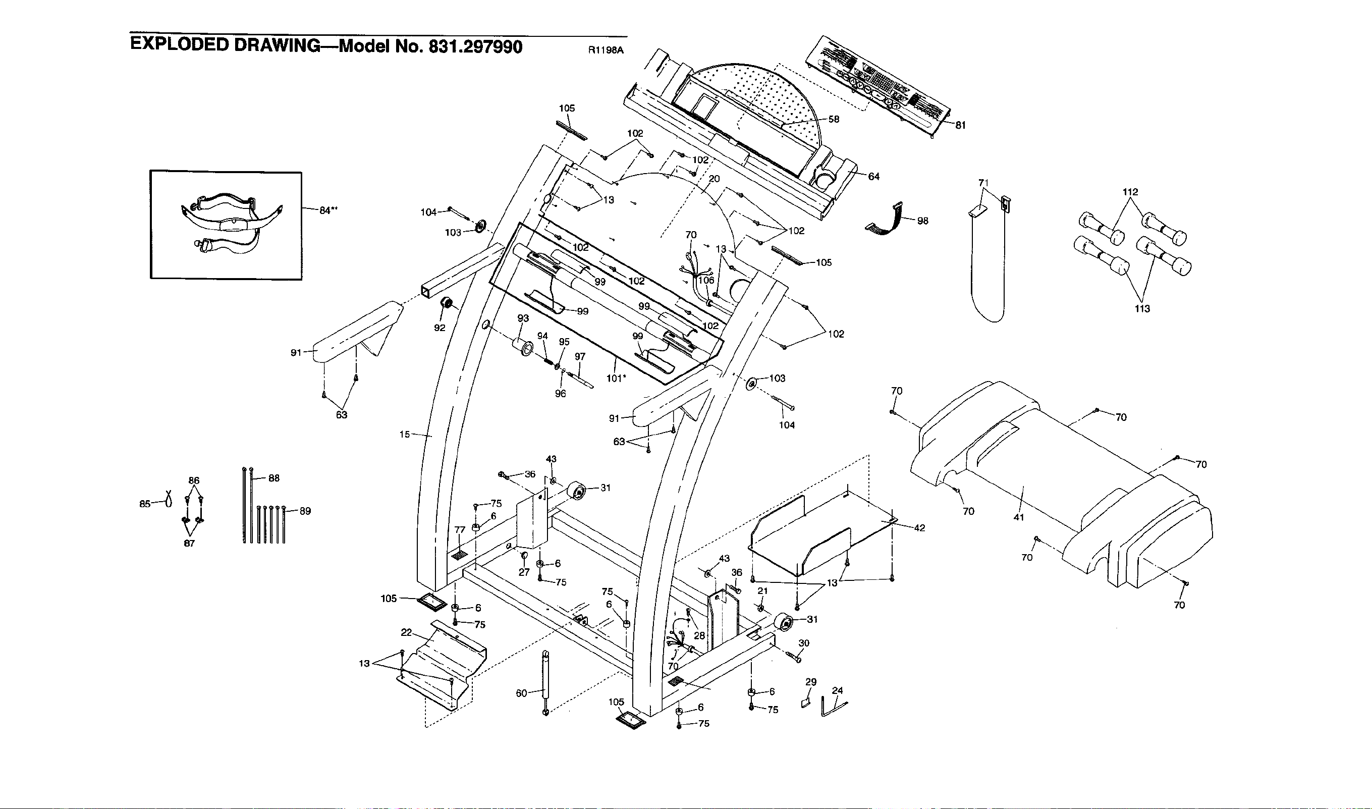
EXPLODED DRAWING--Model No. 831.297990
_84"*
93
92
i
63
R1198A
105
,_ 102
/
9',
97
101"
96
/
7O
71 112
113
86UIi;
87
"'" 105
21
3O
_29 24
5
7O 41
7O
7O
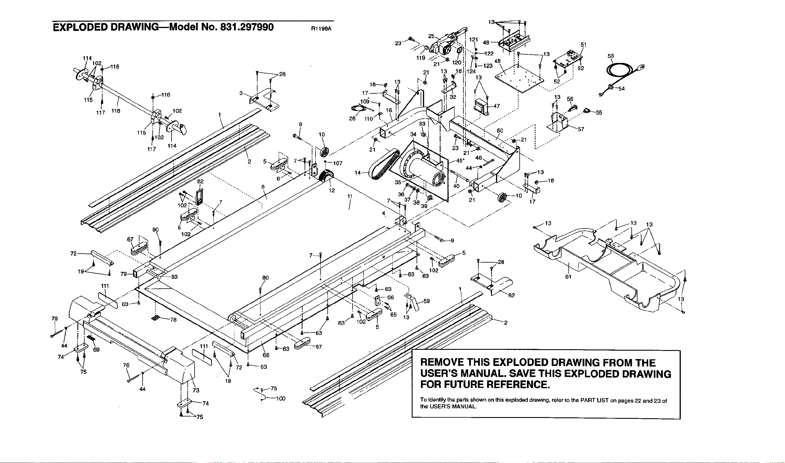
EXPLODED DRAWINGBModel No. 831.297990
114
_116 3_.
115
117 118 102 1
115 !1
117 114
2S_
82 ""'-_
102
80 5l
R1198A
26
9
<,_--107
12 11
/
18--_p
21
J
5O
21"
/45"
35-
36 21
39 .J
51
13 56
_,_18
76
44
75
111
69
_63_.
76
44
J
.J 111
73
80
68
19
_75
'_100
102
62
61
REMOVE THIS EXPLODED DRAWING FROM THE
USER'S MANUAL. SAVE THIS EXPLODED DRAWING
FOR FUTURE REFERENCE.
To identify the partsshownon this explodeddrawing, refer tothe PART LIST on pages 22 and 23 of
the USER'S MANUAL,
13

SEARS
Model No. 831.297990
QUESTIONS?
If you find that:
•you need help assembling or
operating the PROFORM J81i
treadmill
•a part is missing
•or you need to schedule repair
service
call our toll-free HELPLINE
1-800-736-6879
Monday-Saturday, 7 am-7 pm
Central Time (excluding holidays)
REPLACEMENT
PARTS
Ifparts become worn and need
to be replaced, call the following
ton-free number
1-800-FON-PART
(1-800-366-7278)
The model number and sedal numberof your PROFORIVP J8U
treadmill are listedon a decal attached to the frame. See the front
cover of this manual to findthe locationof the decal.
All replacement parts are available for immediate purchase or
special order when you visit your nearest SEARS Service Center.
To requestservice or to order parts bytelephone, call the toll-free
numbers listedat the left.
When requesting helpor service, or orderingpads, please be
prepared to provide thefollowing information:
•The NAME OF THE PRODUCT (PROFORIVPJ81itreadmill)
• The MODEL NUMBER OF THE PRODUCT (831.297990)
•The KEY NUMBER AND DESCRIPTION OF THE PART (see the
EXPLODED DRAWING and PART LIST includedin this manual)
FULL 90 DAY WARRANTY
For 90 daysfrom the date of purchase, iffailure occurs due to defect in material or workmanship in this
SEARS TREADMILL ExERcISER, contact the nearest SEARS Service Center throughoutthe United
States and SEARS will repair or replace the TREADMILL EXERCISER, free ofcharge.
This warrantydoes not applywhen the TREADMILL EXERCISER is used commercially or for rentalpur-
poses.
This warranty gives you specific legal rights, and you may also have other rightswhichvary from state
to state.
SEARS, ROEBUCK AND CO., DEPT. 817WA, HOFFMAN ESTATES, IL 60179
Part No. 149526 H03862-C R1198A Printed in U,':;A_ 1998 ICON Health & Fitness, Inc.