Loading ...
Loading ...
Loading ...
1. Overview
4
Location and Function of Parts
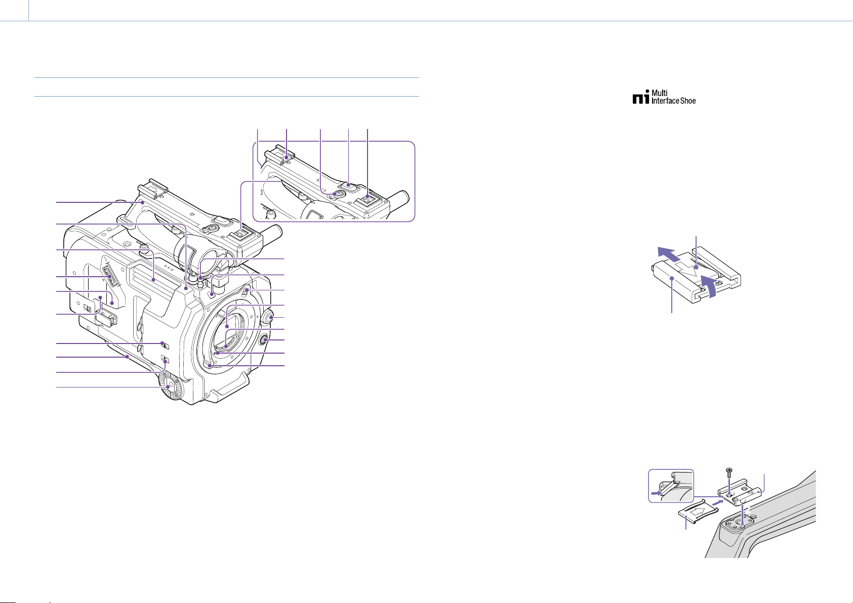
Left Side, Front Side, and Handle
11
12
16
14
13
15
17
18
19
2120 22 23 24
1
4
6
5
3
2
7
9
8
10
1. Handle (page 5)
2. Wi-Fi antenna (page 49)
3. Air outlet
[Note]
Do not cover the air outlet.
4. Viewfinder connector (page 18)
5. REMOTE connector
Connect to general-purpose LANC jack
accessory.
6. USB/multi connector (page 21)
7. INPUT1 (LINE/MIC/MIC+48V) switch
(page 39)
8. Shoulder pad (page 22)
9. INPUT2 (LINE/MIC/MIC+48V) switch
(page 39)
10. Grip attachment (page 21)
11. Tape measure hook
The tape measure hook is on the same plane
as the image sensor. To measure the distance
between the camcorder and the subject
accurately, use this hook as a reference point.
You can attach the end of a tape measure to
the hook to measure the distance from the
subject.
12. Recording/tally lamp (Front) (page 29)
Flashes when the remaining capacity on the
recording media or battery is low.
13. Lens lock ring stopper (page 20)
14. Image sensor
15. Multi-function dial
Press when viewing the image in the
viewfinder to display the direct menu
(page 41).
Turn the dial when a menu is displayed in the
viewfinder to move the cursor up/down to
select menu items or settings. Press to apply
the selected item.
When the menu is not being displayed, the
dial can also function as an assignable dial
(page 41).
16. Lens signal contacts
Connect an E-mount lens.
17. WB SET (white balance set) button
(page 38)
18. Lens lock pin (page 20)
19. Lens lock ring (page 20)
20. GPS module antenna
The GPS antenna and peripheral circuits are
built-in.
21. Accessory shoe (page 4)
22. Handle record START/STOP button
The record button cannot be operated when
the lock lever is in the lock position.
23. Handle zoom lever (page 99)
24. Multi-interface shoe
For details about accessories supported by
the multi-interface shoe, contact your sales
representative.
Attaching the accessory shoe
1 Lift the front edge of the shoe spring, and
pull the spring in the opposite direction to
the arrow engraved on the spring.
Shoe spring
Accessory shoe
1
2 Position the accessory shoe on the
accessory shoe mount, aligning the
protrusions on the shoe with the
corresponding points on the mount, and
tighten the four screws.
3 Insert the shoe spring in the direction of
the arrow so that the U-shaped portion
fits onto the end of the accessory shoe.
Shoe spring
Accessory shoe
3
2
2
Loading ...
Loading ...
Loading ...