
© 2019 Sony Corporation
Solid-State Memory Camcorder
Operating Instructions
PXW-FX9V/PXW-FX9VK
PXW-FX9T/PXW-FX9TK
5-011-867-12 (1)
GB

2
1. Overview
System Configuration........................................3
Location and Function of Parts
..........................4
Screen Display
................................................. 10
2. Preparation
Power Supply ...................................................16
Attaching Devices
............................................18
Configuring Basic Camcorder Operation
......... 24
Using XQD Memory Cards
............................... 25
Using a UTILITY SD/MS Card
........................... 28
3. Shooting
Basic Operation Procedure .............................. 29
Adjusting the Focus
.........................................31
Adjusting the Brightness
................................ 36
Adjusting for Natural Colors
(White Balance)
........................................ 38
Setting the Audio to Record
............................ 39
Useful Functions
..............................................41
Proxy Recording
.............................................. 48
4. Network Functions
Connecting to Other Devices via LAN ..............49
Connecting to the Internet
.............................. 52
Uploading Files
............................................... 54
Using Network Client Mode
............................56
Using Web Remote Control
.............................58
5. Thumbnail Screen
Thumbnail Screen ........................................... 62
Playing Clips
.................................................... 63
Clip Operations ...............................................64
6. Menu Display and Settings
Setup Menu Configuration and Hierarchy .......65
Setup Menu Operations
.................................. 67
User Menu
.......................................................69
Edit User Menu
................................................ 70
Shooting Menu
................................................71
Project Menu
................................................... 80
Paint Menu
......................................................86
TC/Media Menu
..............................................90
Monitoring Menu
............................................ 92
Audio Menu
....................................................95
Thumbnail Menu............................................. 97
Technical Menu
...............................................99
Network Menu
...............................................102
Maintenance Menu
........................................107
Saving and Loading Configuration Data
....... 108
7. External Device Connection
Connecting External Monitors and Recording
Devices
.................................................... 110
External Synchronization
................................111
Managing/Editing Clips using a Computer
.... 112
8. Appendix
Usage Precautions ......................................... 113
Output Formats and Limitations
.................... 115
Troubleshooting............................................. 116
Error/Warning Messages
............................... 118
Items Saved in Files
....................................... 121
Block Diagrams
.............................................. 131
Updating E-mount Lens Software
..................134
Licenses..........................................................135
Specifications
.................................................138
Table of Contents
3
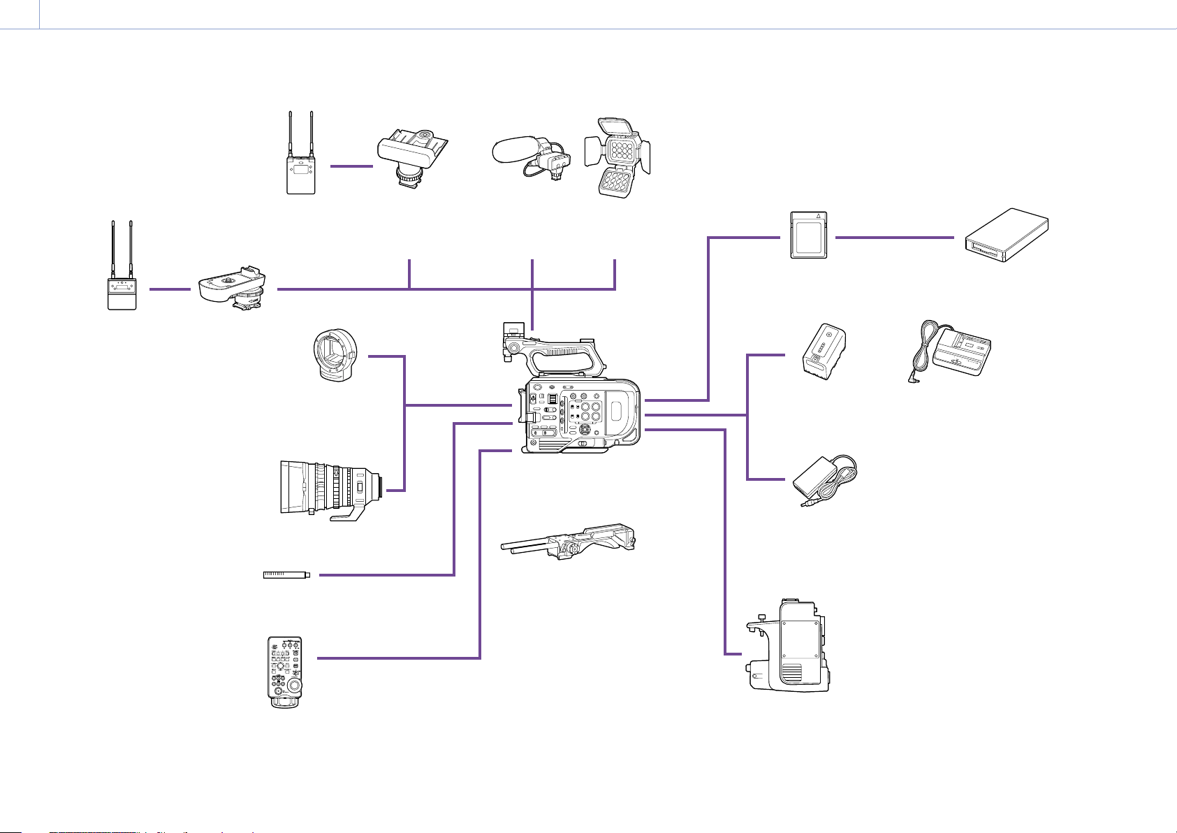
1. Overview
System Configuration
UWP-D21
UWP-D22
UWP-D26
Wireless
Microphone
Package
URX-P03D
Wireless
Microphone
Receiver
SMAD-P3D
Multi-Interface
Shoe Adaptor
SMAD-P5
Multi-Interface Shoe
Adaptor
LA-EA3
LA-EA4
A-mount Adaptor
E-mount lens
ECM-VG1
ECM-MS2
Microphone
RM-30BP
Remote Control Unit
Grip remote control
(supplied)
PXW-FX9V/FX9T
VCT-FS7
Shoulder Adaptor
XLR-K2M
XLR-K3M
XLR Adaptor Kit
HVL-LBPC
Video Light
S/N/M/H/G series
XQD Memory Card
BP-U35, BP-U60,
BP-U70, BP-U90
Battery Pack
AC adaptor
(supplied)
XDCA-FX9
Extension Unit
MRW-E80, MRW-E90
XQD Card Reader
BC-U1A, BC-U2A
Battery Charger
1. Overview
4
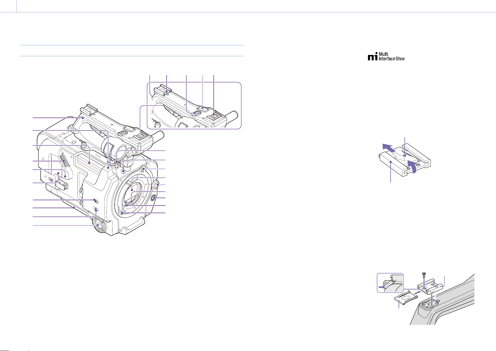
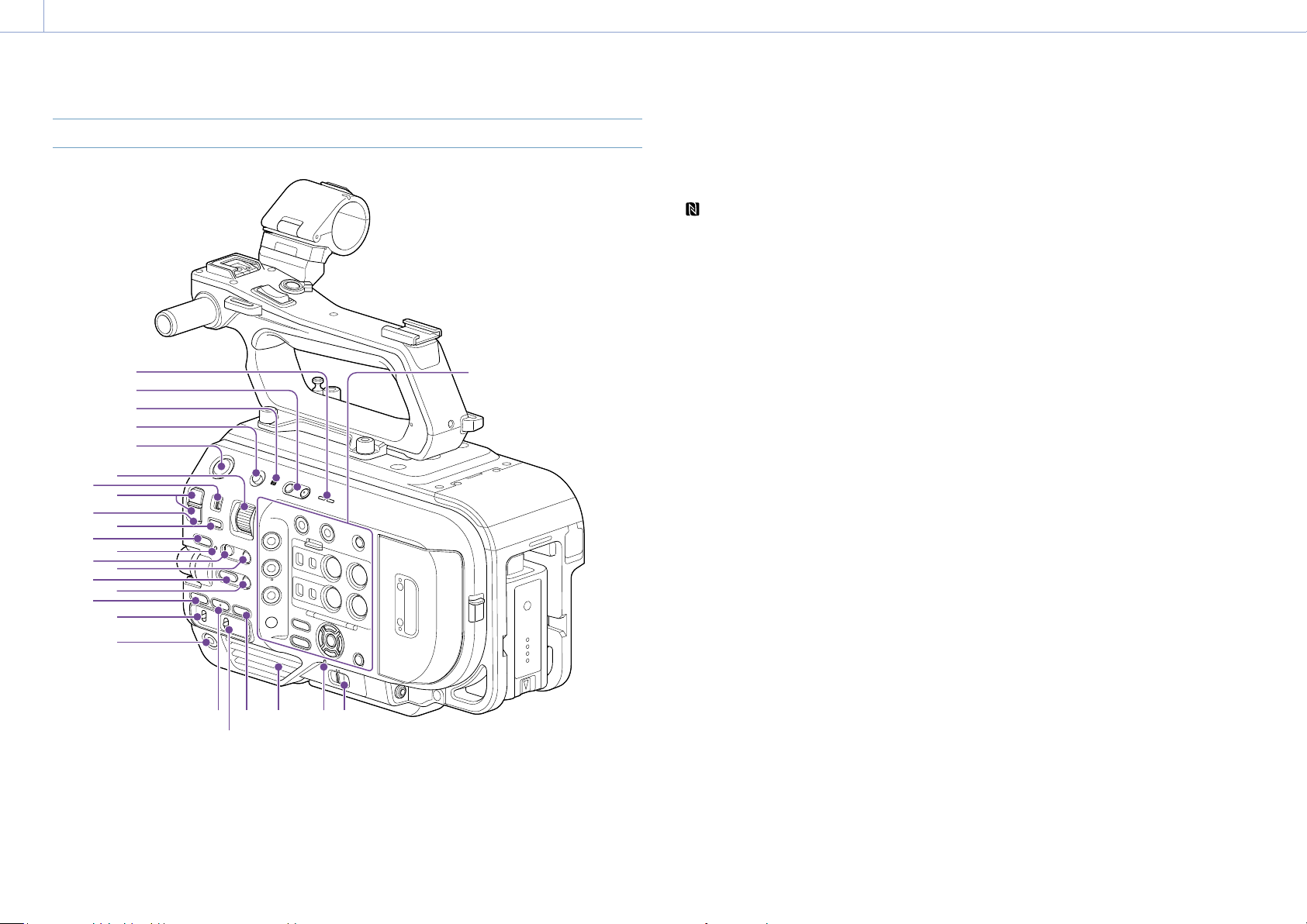
Location and Function of Parts
Left Side, Front Side, and Handle
11
12
16
14
13
15
17
18
19
2120 22 23 24
1
4
6
5
3
2
7
9
8
10
1. Handle (page 5)
2. Wi-Fi antenna (page 49)
3. Air outlet
[Note]
Do not cover the air outlet.
4. Viewfinder connector (page 18)
5. REMOTE connector
Connect to general-purpose LANC jack
accessory.
6. USB/multi connector (page 21)
7. INPUT1 (LINE/MIC/MIC+48V) switch
(page 39)
8. Shoulder pad (page 22)
9. INPUT2 (LINE/MIC/MIC+48V) switch
(page 39)
10. Grip attachment (page 21)
11. Tape measure hook
The tape measure hook is on the same plane
as the image sensor. To measure the distance
between the camcorder and the subject
accurately, use this hook as a reference point.
You can attach the end of a tape measure to
the hook to measure the distance from the
subject.
12. Recording/tally lamp (Front) (page 29)
Flashes when the remaining capacity on the
recording media or battery is low.
13. Lens lock ring stopper (page 20)
14. Image sensor
15. Multi-function dial
Press when viewing the image in the
viewfinder to display the direct menu
(page 41).
Turn the dial when a menu is displayed in the
viewfinder to move the cursor up/down to
select menu items or settings. Press to apply
the selected item.
When the menu is not being displayed, the
dial can also function as an assignable dial
(page 41).
16. Lens signal contacts
Connect an E-mount lens.
17. WB SET (white balance set) button
(page 38)
18. Lens lock pin (page 20)
19. Lens lock ring (page 20)
20. GPS module antenna
The GPS antenna and peripheral circuits are
built-in.
21. Accessory shoe (page 4)
22. Handle record START/STOP button
The record button cannot be operated when
the lock lever is in the lock position.
23. Handle zoom lever (page 99)
24. Multi-interface shoe
For details about accessories supported by
the multi-interface shoe, contact your sales
representative.
Attaching the accessory shoe
1 Lift the front edge of the shoe spring, and
pull the spring in the opposite direction to
the arrow engraved on the spring.
Shoe spring
Accessory shoe
1
2 Position the accessory shoe on the
accessory shoe mount, aligning the
protrusions on the shoe with the
corresponding points on the mount, and
tighten the four screws.
3 Insert the shoe spring in the direction of
the arrow so that the U-shaped portion
fits onto the end of the accessory shoe.
Shoe spring
Accessory shoe
3
2
2
1. Overview: Location and Function of Parts
5
Removing the accessory shoe
Remove the shoe spring as described in step 1
in “Attaching the Accessory Shoe,” unscrew the
four screws, and remove the accessory shoe.
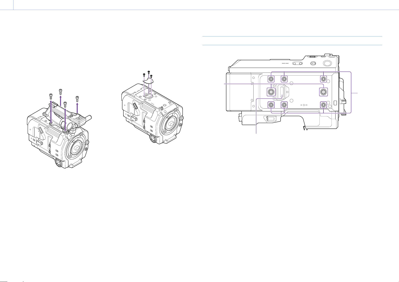
Removing the handle
Remove the four handle attachment screws,
and remove the handle from the camcorder.
Attaching the handle connector
protective cap (supplied)
When using the camcorder with the handle
removed, protect the connector using the
supplied protective cap.
Protecting the connector terminals
Attach the cover to unused connectors to
protect the connector terminals.
Top Side
1
3
2
1. Extension screw holes (3/8 inch)
Compatible with 3/8-16 UNC screws (length of
10.0mm or less).
2. Extension screw holes (1/4inch)
Compatible with 1/4-20 UNC screws (length of
7.0mm or less).
3. Handle connector
1. Overview: Location and Function of Parts
6
Right Side (Front/Top/Bottom)
1
2
3
4
5
7
9
11
13
15
18
6
8
10
12
14
16
17
19
2422
21
20 23 25
Right side (rear)
(page 7)
1. Built-in speaker (page 29)
2. VOLUME (monitor volume adjust) buttons
Adjusts the monitor volume and alarm
volume.
3. (N-Mark)
Touch a smartphone equipped with the
NFC function against the unit to establish a
wireless connection (page 49).
Some smartphones that support wireless
pay systems may not support NFC. For
details, refer to the operation manual for the
smartphone.
NFC (Near Field Communication) is an
international communications protocol for
wireless communication between objects in
close proximity.
4. HOLD switch (page 99)
5. Record START/STOP button
6. ND VARIABLE dial (page 37)
7. ND PRESET/VARIABLE switch (page 37)
8. ND FILTER POSITION up/down buttons
(page 37)
9. ND CLEAR LED (page 37)
10. ND VARIABLE AUTO button (page 37)
11. STATUS button (page 13)
12. FOCUS AUTO LED (page 31)
13. FOCUS switch (page 31)
14. PUSH AUTO FOCUS button (page 33)
15. IRIS function button (page 36)
16. PUSH AUTO IRIS button (page 36)
17. ISO/GAIN function button (page 36)
18. ISO/GAIN (gain select) switch (page 36)
19. ASSIGN (assignable) 9 button (page 41)
20. WHT BAL (white balance) function button
(page 38)
21. WHT BAL (white balance memory select)
switch (page 38)
22. SHUTTER function button (page 37)
23. Air inlet
[Note]
Do not cover the air inlet.
24. POWER indicator (page 29)
25. POWER switch (page 29)
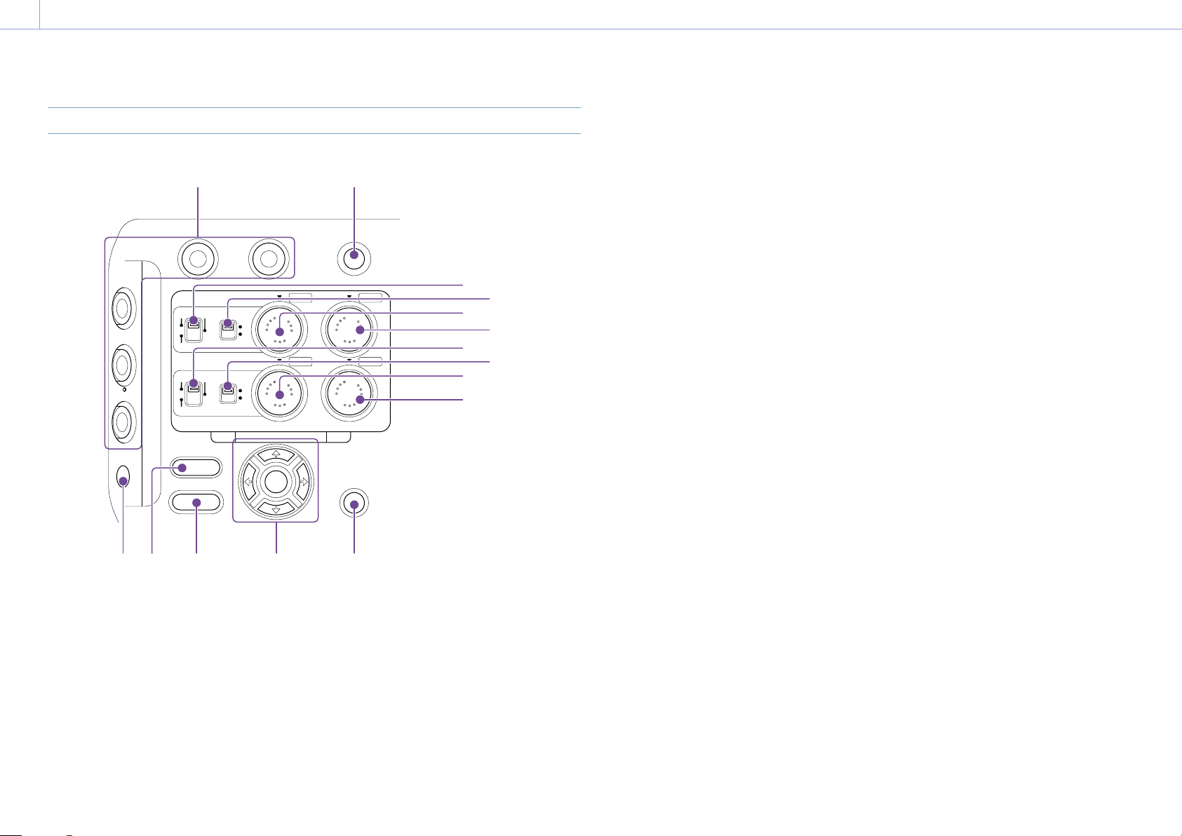
1. Overview: Location and Function of Parts
7
Right Side (Rear)
MENU
THUMBNAIL
EXT
MI SHOE MAN
INT AUTO
SLOT SELECT
AUDIO LEVEL
CANCEL
/
BACK
DISPLAY
S&Q
1
3
EXT
MI SHOE MAN
INT AUTO
7 8
CH
-
1
CH
-
2
CH
-
3
CH
-
4
2
1 2
1415 13
6
3
5
7
8
9
10
1112
4
1. ASSIGN (assignable) 1 to 3, 7 to 8 buttons
(page 41)
2. SLOT SELECT (XQD memory card select)
button (page 29)
3. CH1 INPUT select switch (page 39)
4. CH1 (AUTO/MAN) switch (page 39)
5. AUDIO LEVEL (CH1) dial (page 39)
6. AUDIO LEVEL (CH3) dial (page 39)
7. CH2 INPUT select switch (page 39)
8. CH2 (AUTO/MAN) switch (page 39)
9. AUDIO LEVEL (CH2) dial (page 39)
10. AUDIO LEVEL (CH4) dial (page 39)
11. CANCEL/BACK button (page 63)
12. Arrows (///) and SET button
(page 63)
13. MENU button (page 65)
14. THUMBNAIL button (page 62)
15. DISPLAY (screen display) button
(page 10)

1. Overview: Location and Function of Parts
8
Card Slot, Rear Side, and Terminals
18
19
7
8
9
10
11
14
12
13
23 21
22 20
15
17
16
6
1
2
3
4
5
1. XQD card slot A (page 25)
2. XQD (A) access indicator (page 26)
3. XQD card slot B (page 26)
4. XQD (B) access indicator (page 26)
5. Headphone jack (page 29)
6. SD card access indicator (page 28)
7. UTILITY SD/MS card slot (page 28)
8. Extension unit connector (internal)
(page 23)
9. DC IN connector (page 17)
10. Recording/tally lamp (Rear) (page 29)
11. BATT RELEASE button (page 16)
12. Battery (page 16)
13. Battery pack attachment (page 16)
14. Air inlet
[Note]
Do not cover the air inlet.
15. Internal microphone (page 39)
Narration microphone for recording ambient
sound.
16. SDI OUT 1 connector (page 110)
17. INPUT1 (audio input 1) connector
(page 39)
18. INPUT2 (audio input 2) connector
(page 39)
19. SDI OUT 2 connector (page 110)
20. IN/OUT select switch (page 111)
21.
TC IN/TC OUT (timecode input/output)
connector
(page 111)
22. GENLOCK IN (genlock input)/REF OUT
(sync signal output) connector
(page 111)
23. HDMI OUT connector (page 110)
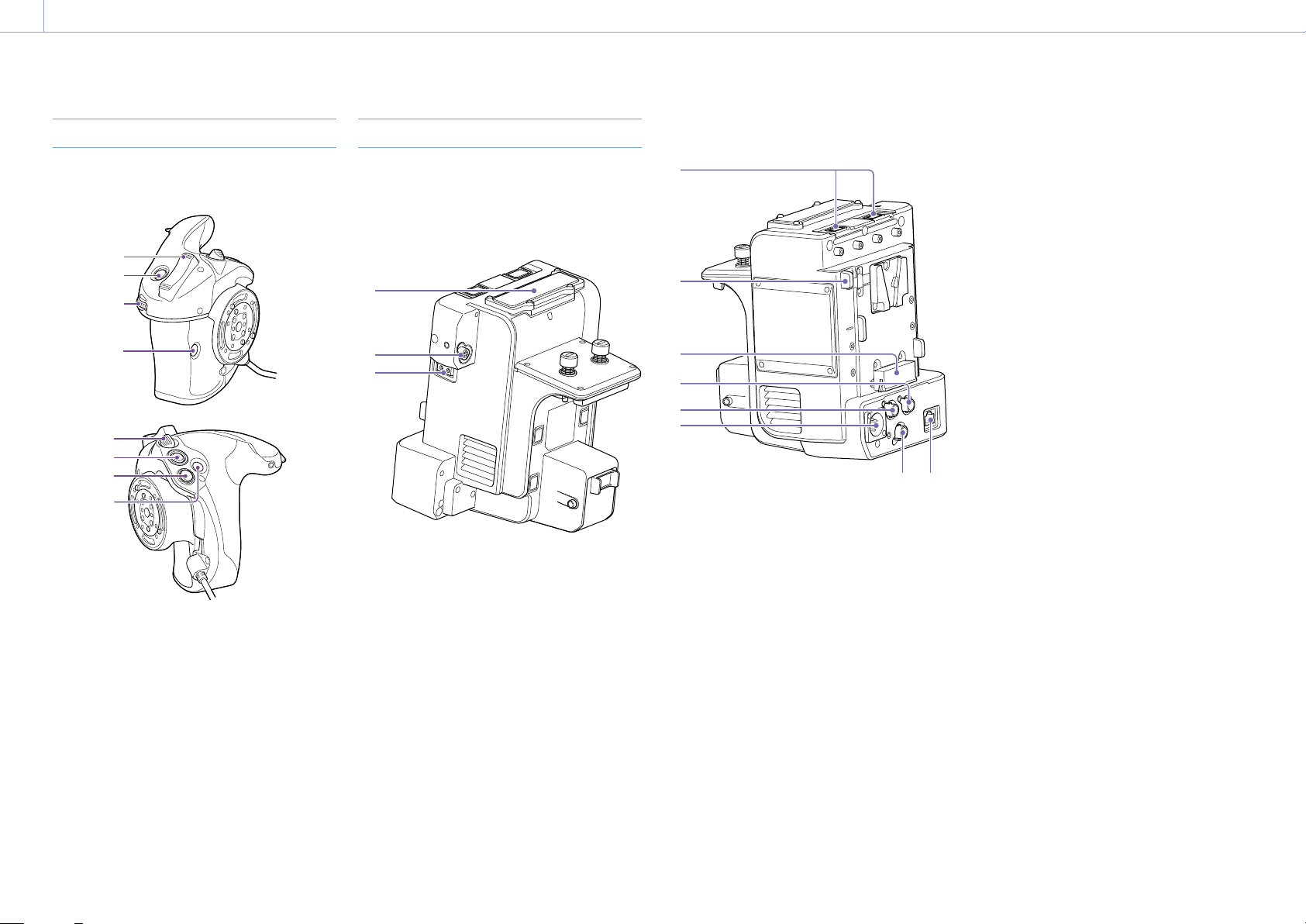
Bottom Side
1
1. Tripod screw holes (1/4inch, 3/8inch)
Attach to a tripod (option, screw length of
5.5mm or less) that supports 1/4-20 UNC or
3/8-16 UNC screws.
Viewfinder
For details about attaching the viewfinder
(supplied), see page 18.
1
2
3
4 5
1. PEAKING button
2. ZEBRA button
3. ASSIGN (assignable) 10 button
(page 41)
4. MIRROR switch
5. Eyepiece attachment hooks
Eyepiece
For details about attaching the eyepiece
(supplied), see page 20.
1 2
1. Diopter adjustment knob
2. Eyecup
1. Overview: Location and Function of Parts
9
Grip Remote Control
For details about attaching the grip remote
control (supplied), see page 21.
1
2
3
4
5
6
7
8
1. Zoom lever
2. ASSIGN (assignable) 4 button
3. Assignable dial
4. ASSIGN (assignable) 6 button
5. Grip rotation lever
6. Record START/STOP button
7. Multi selector (8-way D-pad and SET
button)
8. ASSIGN (assignable) 5 button
XDCA-FX9 Extension Unit (Option)
For details about attaching an XDCA-FX9
Extension Unit (option), see page 23.
Front
1
2
3
1. Wireless receiver insertion slot
2. DC OUT connector (4-pin round type)
12 V DC power output connector.
3. LIGHT connector (2-pin)
12 V DC power output connector.
Rear
2
1
4
6
3
5
7 8
1. USB connectors (type A)
2. Battery release lever
3. Battery connector
4. TC OUT connector (BNC type)
5. REF OUT connector (BNC type)
6. DC IN connector (XLR type, 4-pin)
7. RAW OUT connector (BNC type)
8. LAN connector
[Note]
The RAW OUT connector and wireless receiver are
reserved for future use.
1. Overview
10
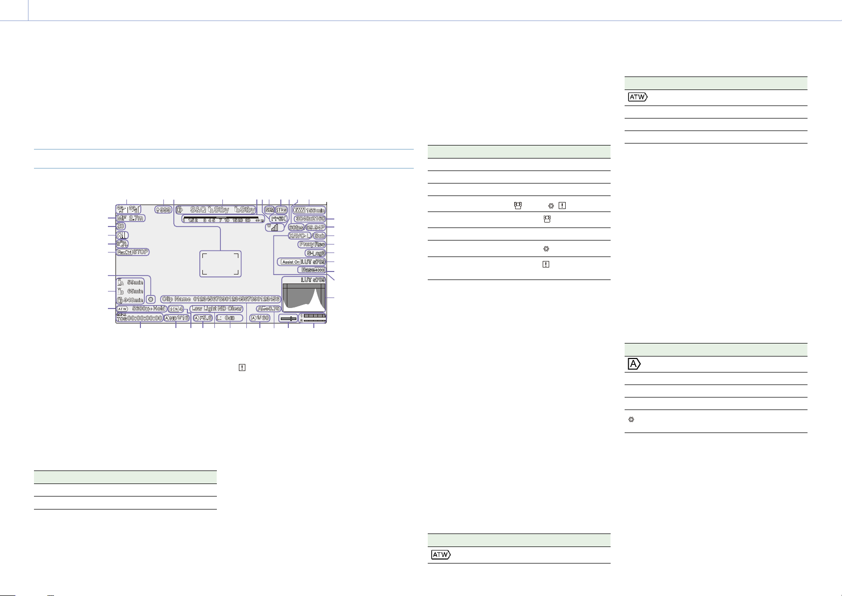
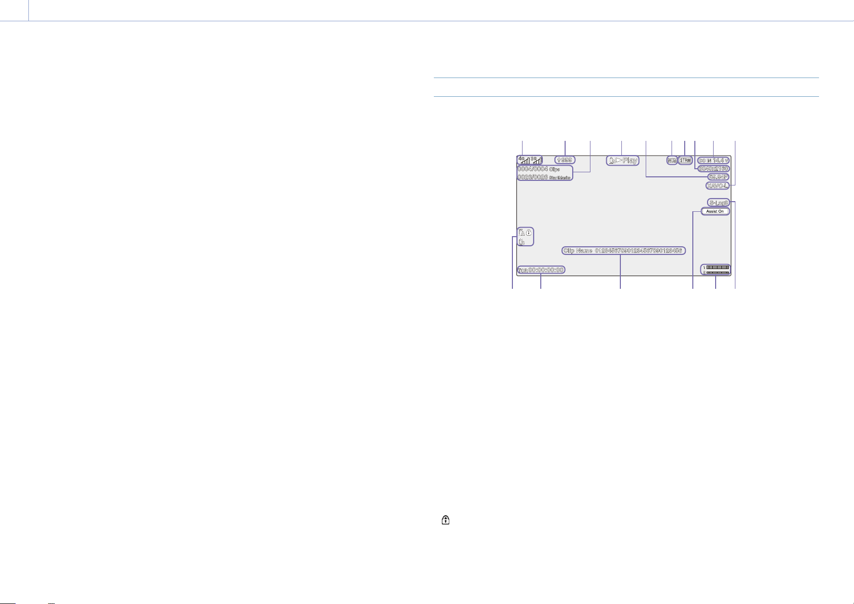
Screen Display
During shooting (recording/standby) and playback, the camcorder status and settings are
superimposed on the image displayed in the viewfinder.
You can show/hide the information using the DISPLAY button.
You can also select to show/hide each item independently (page 92).
Information Displayed on the Screen While Shooting
3 41 2 6 7 8 9 10 115
12
13
14
15
16
17
18
19
20 21 22 23 24 25 26 27 28 29 30
31
32
33
34
35
36
37
38
39
1. Network status indicator (page 12)
Displays the network connection status as an
icon.
2. Upload indicator/remaining files indicator
(page 54)
3. Focus area indicator (page 31)
Displays the focus area for auto focus.
4. Recording mode, slot A/B, Interval Rec
recording interval indicator (page 42)
Display Meaning
Rec
Recording
Stby Recording standby
5. Depth-of-field indicator
6. Imager scan mode indicator (page 24)
A
mark is displayed if there is a mismatch
between the image circle size of the lens and
the effective picture size imager scan mode
setting.
7. Network client mode status indicator
(page 12)
Displays the connection status in network
client mode.
8. Streaming status indicator
9. UWP-D series status indicator
(page 12)
Displays the RF level signal strength as an icon
when a UWP-D series device is connected
to an MI shoe configured for digital audio
transfer.
10. Slow & Quick Motion shooting frame rate
indicator (page 42)
11. Remaining battery capacity/DC IN voltage
indicator (page 16)
12. Focus mode indicator (page 34)
Meaning Display
Focus Hold mode Focus Hold
MF mode MF
AF mode AF
Face detection AF (AF/
/Only/ / )
Face detection icon
Face detection AF icon Only
Registered face icon
AF paused icon during
face detection AF
1)
1) Displayed when there is no registered face and a face
is not detected, or when there is a registered face and
the registered face is not detected.
13. Zoom position indicator
Displays the zoom position in the range 0
(wide angle) to 99 (telephoto) (if a lens that
supports zoom setting display is attached).
The display can be changed to a bar indicator
or focus distance indicator (page 100).
14. GPS status indicator (page 45)
Displays the GPS status.
15. Image stabilization mode indicator
16. SDI output/HDMI output Rec Control
status indicator (page 110)
Displays the output status of the REC control
signal.
17. Focus indicator (page 34)
18. Remaining media capacity indicator
19. White balance mode indicator
Display Meaning
Auto mode
Display Meaning
Hold
Auto mode paused
W:P Preset mode
W:A Memory A mode
W:B Memory B mode
20. Timecode external lock indicator/time
data display (page 29)
Displays “EXT-LK” when locked to the
timecode of an external device.
21. ND filter indicator (page 37)
22. Scene file indicator (page 108)
23. Iris position indicator
Displays the iris position (if a lens that
supports iris setting display is attached).
24. Video level warning indicator
25. Gain indicator (page 36)
Displayed as an EI value when Base Setting
>Shooting Mode (page 80) in the Project
menu is set to Cine EI.
Display Meaning
Auto mode
H Preset H mode
M Preset M mode
L Preset L mode
Temporary adjustment
mode
26. Clip name display (page 62)
27. Shutter mode/shutter speed indicator
(page 37)
28. AE mode/AE level indicator (page 36)
29. Spirit level indicator
Displays the horizontal level in ±1° increments
up to ±15°.
1. Overview: Screen Display
11
30. Audio level meter
Displays the audio level of CH1 and CH2.
CH3 and CH4 can be monitored on the status
screen.
31. Video signal monitor (page 45)
Displays a waveform, vectorscope, and
histogram.
The monitor LUT type of the signal being
monitored is displayed when Base Setting
>Shooting Mode (page 80) in the Project
menu is set to Cine EI.
32. Recording format (codec) indicator
(page 80)
Displays the name of the format for recording
on XQD memory cards.
33. Base Sensitivity indicator/Base ISO
indicator (page 36)
When Base Setting >Shooting Mode
(page 80) in the Project menu is set to
Custom, it displays the base sensitivity set
using ISO/Gain/EI >Base Sensitivity in the
Shooting menu.
When Base Setting >Shooting Mode
(page 80) in the Project menu is set to Cine
EI, it displays the base ISO sensitivity set using
ISO/Gain/EI >Base ISO in the Shooting menu.
34. Gamma display assist/monitor LUT
indicator
Displays the gamma display assist status. The
gamma display assist function can be turned
on/off by assigning Gamma Display Assist to
an assignable button (page 41).
When Base Setting >Shooting Mode
(page 80) in the Project menu is set to
Cine EI, it displays the monitor LUT setting
for recording video on XQD memory cards
(page 78).
35. Gamma indicator (page 86)
Displays the gamma setting.
36. Proxy status indicator
37. 4K & HD (Sub) recording indicator
38. Recording format (frame rate and scan
method) indicator
39. Recording format (picture size) indicator
(page 80)
Displays the picture size for recording on XQD
memory cards.
Information Displayed on the Screen During Playback
The following information is superimposed on the playback picture.
1
11 12 13 14 15 16
2 3 4 5 6 7 8 9 10
1. Network status indicator
2. Upload indicator/remaining files indicator
3. Clip number/total number of clips
4. Playback status indicator
5. Playback format (frame rate and scan
method) indicator
6. Network client mode status indicator
7. Streaming status indicator
8. Playback format (picture size) indicator
9. Remaining battery capacity/DC IN voltage
indicator
10. Playback format (codec) indicator
11. Media indicator
A
mark is displayed if the media is
protected.
12. Time data display
13. Clip name display
14. Gamma display assist indicator
15. Audio level meter
Displays the recording audio level.
16. Gamma indicator
1. Overview: Screen Display
12
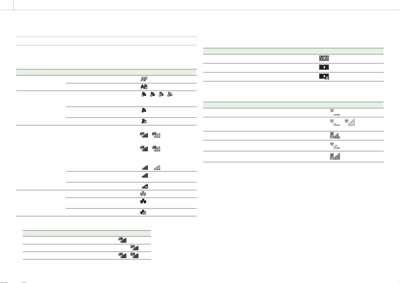
Icon Display
Network connection icon display
Network mode Connection status Icon
Access point mode Operating as an access point
Access point operation error
Station mode Wi-Fi connection
Icon changes according to the signal
strength (4 steps)
Wi-Fi disconnected (including when
establishing connection)
Wi-Fi connection error
Modem
1)
Icon changes according to the 3G/4G
connection signal strength (5 steps)
Icon for signal strength 3 is displayed
for modems that do not report signal
strength.
3G connection
–
4G connection
–
Network connection where
3G/4G cannot be distinguished
–
3G/4G disconnected (including when
establishing connection)
3G/4G connection error
Wired LAN LAN connection
LAN disconnected (including when
establishing connection)
LAN connection error
1) Two modems can be connected when an XDCA-FX9 (option) is attached to the camcorder. When two modems are
connected, the icons change according to the modem status as follows.
Connection status Icon
Two modems connected, only modem 1 in use
Two modems connected, only modem 2 in use
Two modems connected, both in use
Network client mode icon display
Network client mode connection status Icon
Network client mode connected status
Network client mode connection standby status
Network client mode connection error status
UWP-D series icon display
Transmitter status Receive status Icon
Power off Not receiving
Normal transmit status Receiving
–
(receive level (4 steps))
Muting status Receiving (muted)
Remaining battery capacity warning
status
Receiving
(Icon flashing)
Muting and remaining battery capacity
warning status
Receiving
(Icon flashing)

1. Overview: Screen Display
13
Status Screen
You can check the settings and status of the
camcorder on the status screen.
To display the status screen
Press the STATUS button.
To switch to the status screen
Turn the multi-function dial.
Press the / arrow buttons.
To hide the status screen
Press the STATUS button.
Main Status screen
Displays the main functions of the camera and
the free space on the media.
Display item Description
S&Q Frame Rate Frame rate setting for Slow
& Quick Motion shooting
Frequency/Scan System frequency and
scanning method settings
Imager Scan Scan mode of the image
sensor
Media Remain
(A)
Remaining free space on
media in slot A
ND Filter ND filter setting
ISO/Gain/EI ISO/Gain/Exposure Index
setting
Base ISO/
Sensitivity
Base ISO/Base Sensitivity
setting
Codec Codec setting for recording
Media Remain (B) Remaining free space on
media in slot B
Monitor LUT Monitor LUT setting
Shutter Shutter speed or shutter
angle setting
Iris Iris setting
Display item Description
Picture Size Picture size for recording to
XQD memory cards
White Balance White balance setting
Camera Status screen
Displays the camera settings.
Display item Description
White Switch<B> White balance memory B
setting
White Switch<A> White balance memory A
setting
White Switch<P> Preset White setting
ND<Preset> ND filter Preset1 to 3 settings
ISO / Gain<L> ISO/Gain<L> setting
ISO / Gain<M> ISO/Gain<M> setting
ISO / Gain<H> ISO/Gain<H> setting
Base ISO/
Sensitivity
Base ISO/Base Sensitivity
setting
Zebra1 Zebra1 On/Off setting and
level
Zebra2 Zebra2 On/Off setting and
level
Gamma Gamma category and curve
Scene File Scene file in use and its File
ID setting
Audio Status screen
Displays the input setting, audio level meter,
and wind noise reduction filter setting for each
channel.
Display item Description
CH1 level meter Channel 1 audio level meter
CH1 Source Channel 1 input source
CH1 Ref./Sens. Channel 1 input reference
level
CH1 Wind Filter Channel 1 microphone wind
reduction filter setting
Display item Description
CH2 level meter Channel 2 audio level meter
CH2 Source Channel 2 input source
CH2 Ref./Sens. Channel 2 input reference
level
CH2 Wind Filter Channel 2 microphone wind
reduction filter setting
CH3 level meter Channel 3 audio level meter
CH3 Source Channel 3 input source
CH3 Wind Filter Channel 3 microphone wind
reduction filter setting
CH4 level meter Channel 4 audio level meter
CH4 Source Channel 4 input source
CH4 Wind Filter Channel 4 microphone wind
reduction filter setting
Audio Input Level Audio input level (master
volume) setting
Monitor CH Monitor channel setting
HDMI Output CH HDMI output audio channel
setting
Headphone Out Headphone output type
setting
System Status screen
Displays the video signal settings.
Display item Description
Frequency/Scan System frequency and
scanning method settings
Codec Codec setting for recording
Rec Function Enabled special recording
format and settings
Simul Rec 2-slot simultaneous
recording function On/Off
status
Title Prefix Title portion of the clip
name
Imager Scan Scan mode of the image
sensor
Picture Size Picture size for recording to
XQD memory cards
Display item Description
Picture Cache
Rec
Picture cache recording
function On/Off status and
setting
Number Numeric suffix of the clip
name
Shooting Mode Shooting mode setting
4K & HD (Sub)
Rec
4K & HD (Sub) recording
function On/Off status
Proxy Rec Proxy recording function
On/Off status and setting
Genlock Genlock state
Video Output Status screen
Displays the SDI, HDMI, and video output
settings.
Display item Description
SDI1 Output picture size
Output On/Off setting
Color space setting/Monitor
LUT status
SDI2 Output picture size
Output On/Off setting
Color space setting/Monitor
LUT status
HDMI Output picture size
Output On/Off setting
Color space setting/Monitor
LUT status
Streaming Streaming format
information
Streaming output status
Color space setting/Monitor
LUT status
VF
Gamma display assist
setting/Monitor LUT status/
Color space setting
Monitor LUT Monitor LUT setting

1. Overview: Screen Display
14
Assignable Button Status screen
Displays the functions assigned to each of the
assignable buttons.
Display item Description
1 Function assigned to the
ASSIGN 1 button
2 Function assigned to the
ASSIGN 2 button
3 Function assigned to the
ASSIGN 3 button
4 Function assigned to the
ASSIGN 4 button
5 Function assigned to the
ASSIGN 5 button
6 Function assigned to the
ASSIGN 6 button
7 Function assigned to the
ASSIGN 7 button
8 Function assigned to the
ASSIGN 8 button
9 Function assigned to the
ASSIGN 9 button
10 Function assigned to the
ASSIGN 10 button
Focus Hold
Button
Function assigned to the
Focus Hold button of the
lens
Multi Function
Dial
Function assigned to the
multi-function dial
Assignable Dial Function assigned to the
assignable dial
Battery Status screen
Displays information about the battery and DC
IN source.
Display item Description
Detected Battery Type of battery
Remaining Remaining capacity (%)
Charge Count Number of recharges
Display item Description
Capacity Remaining capacity (Ah)
Voltage Voltage (V)
Manufacture
Date
Date of battery manufacture
Video Light
Remaining
Displays the remaining
capacity of the video light
battery.
Power Source Power supply source
Supplied Voltage Supplied power source
voltage
Media Status screen
Displays the remaining capacity and remaining
recording time of recording media.
Display item Description
Media A
information
Displays the media icon
when recording media is
inserted in slot A.
Media A
remaining
capacity meter
Displays the remaining
capacity of recording media
inserted in slot A expressed
as a percentage on a bar
graph.
Media A
remaining
recording time
Displays an estimate of the
remaining recording time of
the recording media
inserted in slot A in units of
minutes under the current
recording conditions.
Media B
information
Displays the media icon
when recording media is
inserted in slot B.
Media B
remaining
capacity meter
Displays the remaining
capacity of recording media
inserted in slot B expressed
as a percentage on a bar
graph.
Display item Description
Media B
remaining
recording time
Displays an estimate of the
remaining recording time of
the recording media
inserted in slot B in units of
minutes under the current
recording conditions.
SD card
information
Displays the media icon
when media is inserted in
the UTILITY SD/MS card slot.
SD card
protection
Displays the lock icon when
the media inserted in the
UTILITY SD/MS card slot is
protected (locked).
SD card
remaining
capacity meter
Displays the remaining
capacity of media inserted in
the UTILITY SD/MS card slot
expressed as a percentage
on a bar graph.
SD card
remaining
capacity
Displays an estimate of the
remaining recording time of
the recording media
inserted in the UTILITY SD/
MS card slot in units of
minutes, or displays the
remaining capacity in units
of GBs.
Rec Button Settings Screen
Displays the settings of the record START/
STOP buttons on the camcorder and handle
(page 44).
Display item Description
Rec Button Displays the slots for
recording controlled by
the recording START/
STOP button.
Handle Rec Button Displays the slots for
recording controlled by
the recording START/
STOP button on the
handle.
GPS Status screen
Displays the GPS positioning status and
information.
Display item Description
GPS GPS signal and positioning
status
Dilution Of
Precision
Positioning accuracy
information
Latitude Latitude information
Longitude Longitude information
Altitude Altitude information
Positioning date
and time
Positioning date and time
Current date and
time
Current date and time
Time Zone Time Zone setting
Network Status screen
Displays the network connection status.
Display item Description
Wireless LAN Wireless network settings
and connection status
Wired LAN Wired LAN network settings
and connection status
Modem 1 Wireless network settings
and connection status of
modem (option)
Modem 2 Wireless network settings
and connection status of
modem (option)

1. Overview: Screen Display
15
NCM/Streaming Status screen
Displays the connection status in network
client mode and the streaming status.
Display item Description
Network Client
Mode Status
Network client mode status
CCM Name Name of CCM connected in
network client mode
CCM Address Address of CCM connected
in network client mode
QoS Streaming1
Bit Rate
Streaming bit rate 1
QoS Streaming2
Bit Rate
Streaming bit rate 2
Streaming Status Streaming status
Streaming Type Currently selected streaming
type
File Transfer Status screen
Displays file transfer information.
Display item Description
Auto Upload
(Proxy)
Auto Upload (Proxy) function
On/Off status
Job Status
(Remain / Total)
Remaining number of jobs
and total number of jobs
Total Transfer
Progress
Transfer progress of all jobs
Default Upload
Server
Name of Auto Upload
(Proxy) destination server
Current File
Transfer Progress
Transfer progress of current
file transfer
Current
Transferring File
Name
Name of file currently being
transferred
Server Address Address of file transfer
destination server
Destination
Directory
Destination directory of file
transfer destination server

16
2. Preparation
Power Supply
You can use a battery pack or AC power
supply from an AC adaptor.
For safety, use only the Sony battery packs and
AC adaptors listed below.
Lithium-ion battery packs
BP-U35
BP-U60
BP-U70
BP-U90
Battery chargers
BC-U1A
BC-U2A
AC adaptor (supplied)
A V-shoe battery can be used when an
XDCA-FX9 Extension Unit is attached.
For safety, use only the Sony battery packs and
AC adaptors listed below.
Lithium-ion battery packs
BP-GL95B
AC adaptor
AC-DN10A
[CAUTION]
Do not store battery packs in locations
exposed to direct sunlight, flame, or high
temperature.
[Notes]
When operating from an AC power source, use the
supplied AC adaptor.
Always set the POWER switch to the Off position
before connecting a battery or AC adaptor. If it is
connected with the POWER switch in the On position,
the camcorder may be unable to start in some cases.
If the camcorder cannot be started, set the POWER
switch to the Off position and disconnect the battery
pack or AC adaptor temporarily, then wait about
30 seconds before attempting to connect again. (If
the AC adaptor is connected while the camcorder is
operating from the battery pack, it can be connected
with the POWER switch in the On position without
problem.)
When using an AC-DN10A adaptor and peripheral
devices are attached to the camcorder, make sure
that the total power consumption of the peripheral
devices is less than 25W.
Using a Battery Pack
To attach a battery pack, plug the battery pack
into the attachment (page 8) as far as it
will go, and then slide it down to lock it into
position.
To remove a battery pack, press and hold the
BATT RELEASE button (page 8), slide the
battery pack up and then pull it out of the
attachment.
BATT RELEASE
button
[Notes]
Before attaching a battery pack, charge the battery
using the dedicated BC-U1A or BC-U2A battery
charger.
Charging a battery immediately after use while it is
still warm may not fully recharge the battery.
Checking the remaining capacity
When shooting/playing using a battery pack,
the remaining battery capacity is displayed in
the viewfinder (page 10).
Icon Meaning
91% to 100%
71% to 90%
51% to 70%
31% to 50%
11% to 30%
0% to 10%
The camcorder indicates the remaining
capacity by calculating the available time with
the battery pack if operation is continued at
the current rate of power consumption.
When using an extension unit
When using the XDCA-FX9 Extension Unit,
the battery voltage or the remaining battery
capacity is displayed, depending on the
battery used.
[Note]
The camcorder battery pack cannot be attached when
an XDCA-FX9 unit is attached to the camcorder. You
must attach a battery pack to the XDCA-FX9 or connect
an external power supply.
If the battery pack charge becomes low
If the remaining battery charge falls below a
certain level during operation (Low Battery
state), a low-battery message appears, the
recording/tally lamp starts flashing, and a
beep sound will warn you.
If the remaining battery charge falls below
the level at which operation cannot continue
(Battery Empty state), a battery-empty
message appears.
Replace with a charged battery pack.
Changing the warning levels
The Low Battery level is set to 10% of full
battery charge and the Battery Empty level is
set to 3% by factory default. You can change
the warning level settings using Camera
Battery Alarm (page 100) in the Technical
menu.

2. Preparation: Power Supply
17
Using AC Power
Connecting the camcorder to an AC power
source allows use without worrying about the
need to recharge the battery pack.
DC IN connector
AC adaptor
Power cord
Connect the AC adaptor to the DC IN
connector on the camcorder, and connect the
power cord (supplied) to an AC power source.
If the output voltage from the AC
adaptor becomes low
If the output voltage from the AC adaptor falls
below a certain level during operation (DC Low
Voltage1 state), a message appears informing
you that the AC adaptor output voltage has
dropped, the recording/tally lamp starts
flashing, and a beep sound is emitted.
If the output voltage from the AC adaptor falls
below the level at which operation cannot
continue (DC Low Voltage2 state), a message
appears informing you that the AC adaptor
output voltage is too low.
If this occurs, the AC adaptor may be faulty.
Check the AC adaptor, as required.
[Tip]
If an AC power source is used while the battery is
attached, the camcorder will automatically switch to
battery power if the output voltage of the AC adaptor
drops.
Changing the warning levels
The DC Low Voltage1 level is set to 16.5 V and
the DC Low Voltage2 level is set to 15.5 V by
factory default. You can change the warning
level settings using Camera DC IN Alarm
(page 100) in the Technical menu.
AC adaptor
Do not connect and use an AC adaptor in a
confined space, such as between a wall and
furniture.
Connect the AC adaptor to the nearest AC
power source. If a problem occurs during
operation, immediately disconnect the
power cord from the AC power source.
Do not short-circuit the metal parts of the
plug of the AC adaptor. Doing so will cause
a malfunction.
The battery cannot be charged while
attached to the camcorder, even if the AC
adaptor is connected.

2. Preparation
18
Attaching Devices
Clamp Lever Operation
Operate the clamp levers when attaching/
removing or adjusting the position of the
microphone and viewfinder.
When attaching, turn the clamp lever
clockwise to secure the rod.
When removing or adjusting the position, turn
the clamp lever counterclockwise to loosen
the clamp lever.
If a clamp lever is in a position that makes it
difficult to turn, pull the clamp lever off and
rotate it to an angle that will make operation
easier. Then place the clamp lever back on.
Clamp lever
Adjusting the Microphone Holder
Position
Loosen the clamp lever, and turn the
microphone holder to move it forward/
backward to adjust the position.
Clamp lever
Microphone holder and microphone
orientation
Attach so that the microphone holder and
microphone are oriented as shown in the
following diagram.
Replacing the Microphone Rod
[Notes]
The microphone rod is attached when shipped from
the factory.
Attach/remove the microphone rod while the
camcorder is turned off.
Attach/remove the microphone rod with the body
cap attached so as not to damage the image sensor.
1 Loosen the screw.
2 Withdraw the microphone rod.
3 Attach the microphone rod in the reverse
sequence.
Attaching the Viewfinder
[Note]
Attach/remove the viewfinder while the camcorder
is turned off. If the viewfinder is removed while the
camcorder is turned on, the camcorder will restart
automatically.
1 Loosen the viewfinder clamp lever, and
insert the viewfinder onto the microphone
rod.
Clamp lever
2 Adjust the left/right positioning of the
viewfinder, tighten the clamp lever,
connect the viewfinder cable to the
viewfinder connector of the camcorder,
and secure the viewfinder cable in the
cable clamper.
Cable clamper
[Note]
Check that the viewfinder is securely attached. The
viewfinder may fall off during shooting if the clamp
lever is loose.
2. Preparation: Attaching Devices
19
Adjusting the viewfinder orientation
Tilt the viewfinder up/down to adjust the
angle of the viewfinder.
You can adjust the angle so that the
viewfinder is facing the subject. Setting the
MIRROR switch to the B/T position flips the
left and rights sides of the image on the
LCD screen, but the image is recorded in the
correct orientation.
Adjusting the viewfinder position
90° angle adjustment
If a square-shaped clamp spacer is attached
to the rod connection joint, you can adjust the
position of the viewfinder in 90° increments.
Temporarily remove the viewfinder to adjust
the angle, then reattach the viewfinder.
Arbitrary angle adjustment
If a circular-shaped clamp spacer is attached
to the rod connection joint, you can turn the
viewfinder on the rod to adjust the position of
the viewfinder.
If the viewfinder is turned 180° as shown in the
following diagram, set the MIRROR switch to
the ROT position to flip the image display and
text display horizontally and vertically.
[Note]
When attaching a circular-shaped clamp spacer, attach
to a commercial ø15mm rod.
[Tip]
A circular-shaped clamp spacer is attached by factory
default.
Changing the clamp spacer
Remove the clamp spacer as shown in the
following diagram, align the protrusion on
the square-shaped spacer or circular-shaped
spacer with the groove in the clamp, and
insert the spacer.
Protrusion
Protrusion
Groove
Groove
[Note]
Always attach a washer. If a washer is not attached, the
clamping force on the rod may be insufficient and may
cause the viewfinder to fall off.
You can determine the shape of the spacer as
shown in the following diagrams.
Square-shaped clamp spacer
Square mark
Circular-shaped clamp spacer
Circle mark
Removing the viewfinder
Loosen the viewfinder clamp lever, and
use the reverse procedure of attaching the
viewfinder.
2. Preparation: Attaching Devices
20
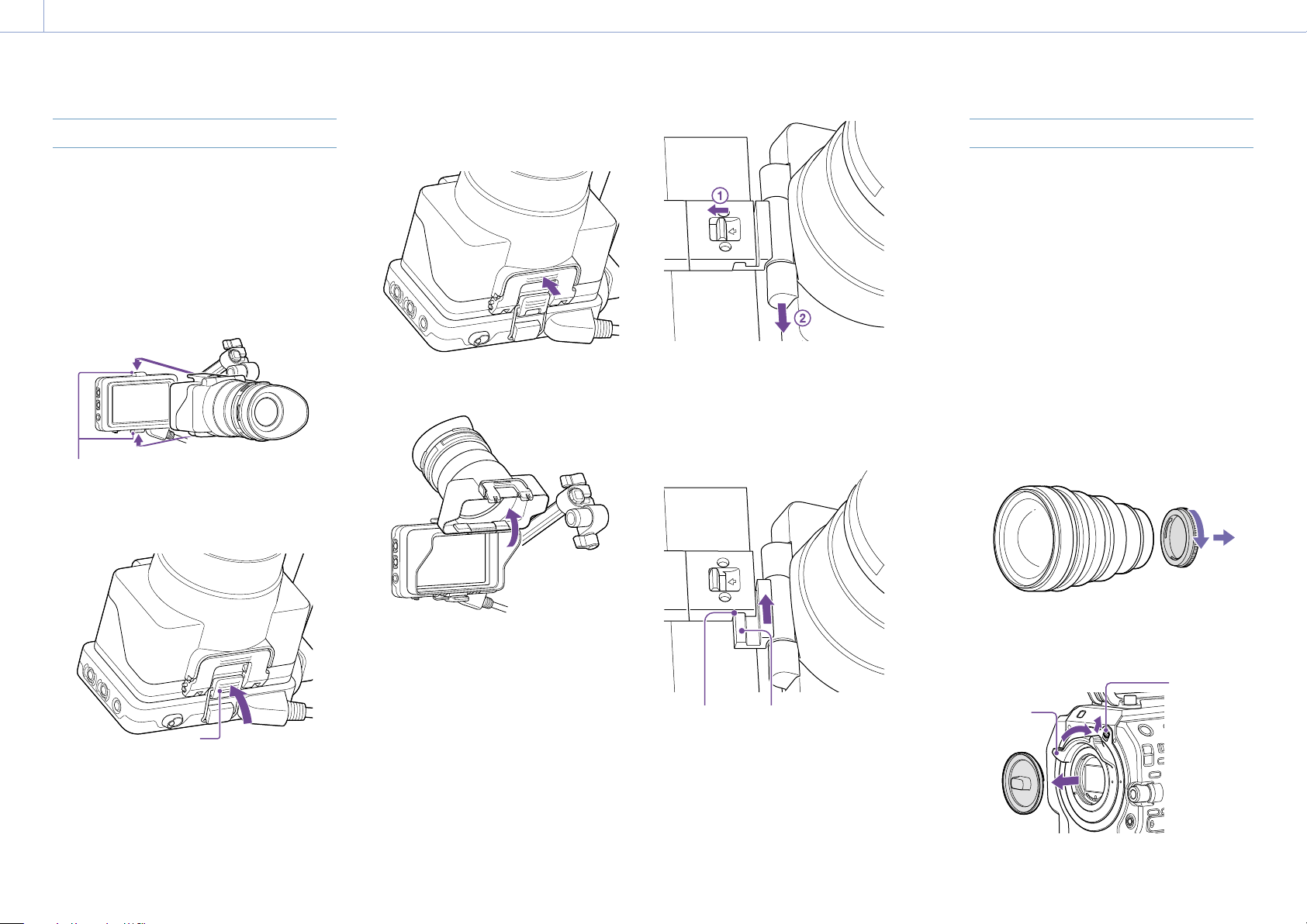
Attaching the Eyepiece
[Note]
Attach/remove the eyepiece while the camcorder is
turned off.
1 Attach the hook on the top of the
eyepiece to the hook on the top of the
viewfinder, and attach the metal clip on
the bottom of the eyepiece to the hook
on the bottom of the viewfinder.
Attachment hooks
2 Push the lock plate on the bottom of the
eyepiece in the direction of the arrow to
lock the eyepiece into position.
Lock plate
Opening the eyepiece
Press the button indicated by the arrow.
Open the eyepiece upwards when the lock
disengages. The viewfinder is directly visible
when the eyepiece is opened.
Removing the rear part of the eyepiece
With the eyepiece opened upwards, release
the eyepiece lock in the direction of the arrow
(), and slide the rear part of the eyepiece out
in the direction of the arrow (). When the
rear part of the eyepiece is removed, the front
of the eyepiece can be used instead of a hood.
Attaching the rear part of the eyepiece
When attaching the rear part of the eyepiece,
align the projection of the hinge with the
guide groove, and push it in the direction of
the arrow in the following diagram until it
locks.
Guide groove Protrusion
Removing the eyepiece
Unclip the eyepiece lock, and remove the
eyepiece from the viewfinder.
Attaching a Lens
[CAUTION]
Do not leave the lens facing the sun. Direct
sunlight can enter through the lens, be
focused in the camcorder, and may cause a
fire.
[Notes]
Attach/remove a lens while the camcorder is turned
off.
A lens is a precision component. Do not place the lens
on a surface with the lens mount face down. Attach
the supplied lens mount cap.
[Tip]
For details about lenses supported by the camcorder,
contact your Sony service representative.
Attaching an E-mount lens
1 Remove the cover from the lens.
2 Release the lens lock ring stopper, turn
the lens lock ring clockwise, and remove
the body cap from the camcorder.
Lens lock
ring
Lens lock
ring stopper
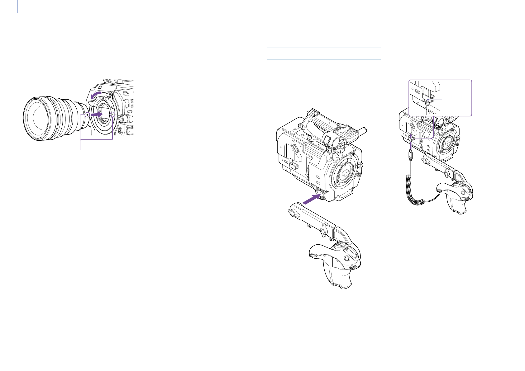
2. Preparation: Attaching Devices
21
3 Align the lens mount mark (white) with
the camcorder, carefully insert the lens,
and slowly turn the lens lock ring
counterclockwise to secure the lens.
Mount marks (white)
[Notes]
If the lens lock ring stopper does not return to the
lock position when the lens is attached, move the
stopper to the lock position manually.
When attaching a lens, align the mount mark (white)
on the lens lock ring with the mount mark (white) on
the camcorder.
Attaching an A-mount lens
To use an A-mount lens, attach a lens mount
adaptor (option) and then attach the A-mount
lens.
[Note]
When using an A-mount lens, the iris is set manually
and focus is set to MF.
Removing a lens
Remove a lens using the following procedure.
1 Release the lens lock ring stopper, and
turn the lens lock ring clockwise while
firmly supporting the lens.
2 Pull the lens out in the forward direction.
[Notes]
When removing a lens, align the mount mark on the
lens lock ring with the mount mark on the camcorder.
Grasp the lens securely in your hand to prevent the
lens from falling.
If another lens will not be attached immediately,
always attach the body cap.
Iris adjustments for lenses with Auto Iris
switch
When the lens Auto Iris is set to AUTO, the
iris is adjusted automatically and can also be
adjusted manually from the camcorder.
When the lens Auto Iris is set to MANUAL,
the iris can only be adjusted using the lens
ring. Iris operation from the camcorder has
no effect.
Focus adjustments for lenses with focus
switch
When the lens focus switch is set to AF/MF
or AF, the focus is adjusted automatically
and can also be adjusted manually from a
remote control unit.
When the lens focus switch is set to MF, the
focus is adjusted using the lens ring and can
also be adjusted manually from a remote
control unit.
[Note]
When using an A-mount lens, manual adjustment
from a remote control unit may not be available.
When the lens focus switch is set to Full
MF, the focus can only be adjusted using
the lens ring. Focus operation from the
camcorder has no effect.
Attaching to a tripod
Use the tripod screw holes on the camcorder
when attaching to a tripod. Using the tripod
mount on the lens may cause damage.
Attaching the Grip Remote Control
[Note]
Attach/remove the grip remote control while the
camcorder is turned off.
1 Attach the arm to the grip attachment,
and tighten the screw.
2 Connect the grip remote control cable to
the USB/multi connector on the
camcorder, and secure the cable in the
cable clamper.
Clamper
[Notes]
When attaching the grip remote control cable, secure
the cable in the cable clamper to prevent damaging it.
Check that the arm is securely attached to the
camcorder. The camcorder may fall while shooting if
the screw is loose.
Do not support the weight of the camcorder by
holding just the grip remote control.
After connecting the grip remote control cable, always
lock the cable in the clamper. Pulling on the cable
with force during use may damage the connector.
If the grip cable gets in the way, secure it using the
cable clamper in the center of the arm.
2. Preparation: Attaching Devices
22
Adjusting the position of the grip
remote control
Loosen the arm mounting screw, adjust the
angle of the arm (1), and then tighten the
screw.
Loosen the arm extension screw, adjust the
length of the arm (2), and then tighten the
screw.
Press the grip rotation lever (page 9) to
adjust the angle of the grip remote control
(3).
2
3
1
Attaching the grip close to the
camcorder
1 Remove the arm mounting screw (1).
2 Loosen the arm extension screw (2), and
extend the arm until a hole becomes
visible (3).
1
2
3
[Note]
After extending the arm, securely tighten the screw.
3 Connect the grip remote control cable to
the USB/multi connector on the
camcorder.
4 Align the protrusion on the arm with the
groove in the grip attachment point, and
secure in position using the screw
removed in step 1.
Adjusting the Position of the
Shoulder Pad
You can slide the shoulder pad forward or
backward. Adjust the position of the shoulder
pad so that the camcorder is easy to operate
when placed on your shoulder.
2
1
3
1
3
1
3
Shoulder pad
1 Loosen the three shoulder pad screws.
2 Slide the shoulder pad forward/backward
to the desired position.
3 Securely tighten the screws.
2. Preparation: Attaching Devices
23
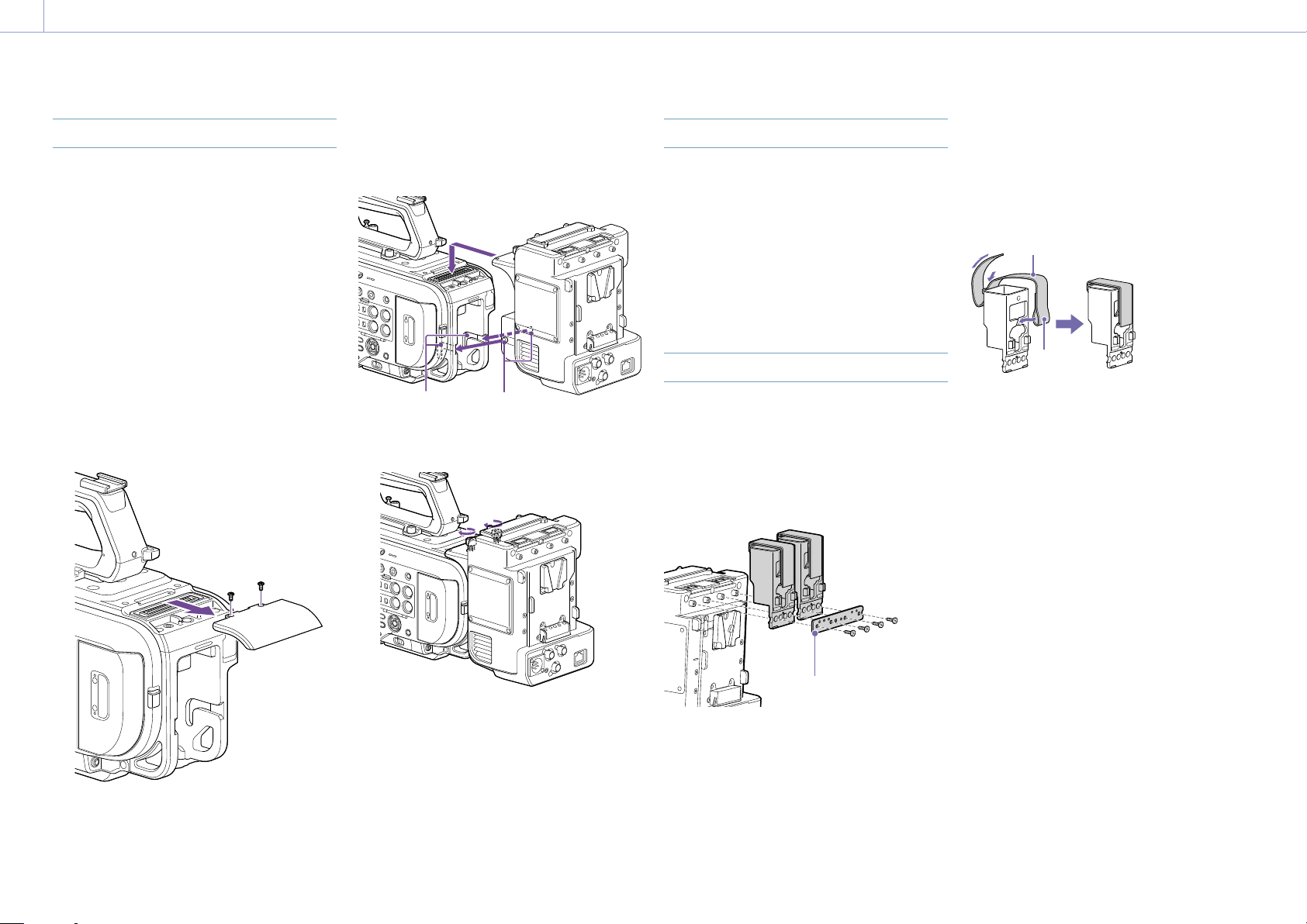
Attaching the XDCA-FX9
You can add functions to the camcorder, such
as a V-shoe battery or wired LAN, by attaching
an XDCA-FX9 Extension Unit (option) to the
camcorder.
[Notes]
The camcorder battery pack cannot be attached
when an XDCA-FX9 unit is attached to the camcorder.
You must attach a battery pack to the XDCA-FX9 or
connect an external power supply.
Attach/remove the XDCA-FX9 while the camcorder is
turned off.
1 Remove the battery pack (page 16)
attached to the camcorder.
2 Remove the two screws, and remove the
cover of the extension unit connector
block from the camcorder.
3 Align the protrusions of the XDCA-FX9
with the left and right grooves of the
camcorder and slide it all the way in and
then down into the connector block.
Grooves
Protrusions
4 Tighten the two screws on the top of the
XDCA-FX9 to secure the XDCA-FX9.
Removing the XDCA-FX9
Loosen the two screws on the top of the
XDCA-FX9, and remove the XDCA-FX9 from the
camcorder.
Attaching a V-Shoe Battery
Insert the V-shoe battery into the battery pack
attachment on the XDCA-FX9.
Removing a V-shoe battery
Pull the V-shoe battery out from the battery
pack attachment on the XDCA-FX9 while
holding down the battery release lever.
Attaching the Dongle Guards
You can attach a dongle guard to protect a
modem or other USB device attached to a USB
connector.
Attach the dongle guard and dongle guard
mounting bracket to the extension unit, and
secure in position using mounting bracket
screws.
Dongle guard mounting
plate
Attaching using fastener strap
Attach the fastener strap to the dongle guard
to secure a USB device in place.
Attach the loop of the strap to the back of
the dongle guard and pass the strap over the
guard as shown below.
Fastener strap
Loop

2. Preparation
24
Configuring Basic Camcorder Operation
The initial settings screen appears in the
viewfinder the first time the camcorder is
turned on or after the backup battery has
become completely discharged.
Set the date and time of the internal clock
using this screen.
Before shooting, configure the basic operation
of the camcorder to suit the application.
Time Zone
Time Zone sets the time difference from UTC
(Coordinated Universal Time). Change the
setting as required.
Setting the Date and Time
Use the arrow buttons (page 7) or the
multi-function dial (page 4) to select items
and settings, then press the SET button or
multi-function dial to apply the settings and
start the clock running.
Once the settings screen is closed, you
can change the date, time, and time zone
settings using Clock Set (page 107) in the
Maintenance menu.
[Notes]
If the clock setting is lost because the backup battery
becomes fully discharged due to power being
disconnected for an extended period (no battery pack
and no DC IN power source), the initial settings screen
will be displayed when you next turn the camcorder
on.
While the initial settings screen is displayed, no other
operation, except turning the power off, is permitted
until you finish the settings on this screen.
The camcorder has a built-in rechargeable battery for
storing the date, time, and other settings even when
the camcorder is turned off. For details about the
built-in rechargeable battery, see page 113.
Shooting Mode
You can switch the shooting mode between
“Custom mode” to create images flexibly on-
site, and “Cine EI mode” (where the camcorder
is operated similarly to a film camera, with
footage developed in post production).
Select the mode using Base Setting
(page 80) >Shooting Mode in the Project
menu.
[Notes]
Cine EI mode has the following limitations.
Functions that cannot be adjusted automatically
(tracking)
– White balance
– Gain
– Shutter
Functions that cannot be configured
– ISO sensitivity/gain (set to base ISO sensitivity
(fixed))
– Paint menu settings (all are disabled)
– Scene File (disabled)
The following functions are available in Cine EI mode
only.
Exposure Index
Monitor LUT
When the shooting mode is set to Cine EI
mode, select the base color space for the
recording signal and output signal. The color
space selected here is the color space of the
video output when MLUT is set to Off.
Select the color space using Cine EI Setting
>Color Gamut (page 81) in the Project
menu.
S-Gamut3.Cine/SLog3: Easy to adjust color
gamut for digital cinema (DCIP3).
S-Gamut3/SLog3: Wide color gamut, for
compatibility with future standard gamuts,
optimized using Sony image distortion
correction technology.
System Frequency
Select the frequency using Rec Format
>Frequency (page 80) in the Project menu.
The camcorder may reboot automatically after
switching, depending on the selected value.
[Note]
You cannot switch the system frequency during
recording or playback.
Imager Scan Mode
You can set the effective picture size and
resolution of the image sensor.
Select the mode using Rec Format
(page 80) >Imager Scan Mode in the Project
menu.
FF 6K: Full-frame size at 6K resolution.
S35 4K: Super 35mm size at 4K resolution.
FF 2K: Full-frame size at 2K resolution.
S35 2K: Super 35mm size at 2K resolution.
[Notes]
You cannot switch the imager scan mode during
recording or playback.
When the imager scan mode is set to FF 2K or S35 2K,
the recording format setting is restricted to 1920×1080
resolution.
Codec
Select the codec using Rec Format >Codec
(page 80) in the Project menu.
[Note]
You cannot switch the codec during recording or
playback.
Video Format
You can set the video format for recording.
Select a format using Rec Format >Video
Format (page 80) in the Project menu.
[Notes]
You cannot switch the video format during recording
or playback.
Restrictions may apply to the signal from the SDI OUT
and HDMI OUT connectors, depending on the video
format setting.

2. Preparation
25
Using XQD Memory Cards
The camcorder records audio and video on XQD memory cards (available separately) inserted in
the card slots.
About XQD Memory Cards
Use the following Sony XQD memory cards in the camcorder.
For details on operations with media from other manufacturers, refer to the operating
instructions for the media or consult the manufacturer’s information.
S-series XQD memory cards (QD-S64E/S32E/S64/S32)
H-series XQD memory cards (QD-H32/H16)
N-series XQD memory cards (QD-N64)
M-series XQD memory cards (QD-M128A/M64A/M32A)
G-series XQD memory cards (QD-G240F/G120F/G256E/G128E/G64E/G32E/G128A/G64A/G32A)
The use of memory cards other than Sony XQD memory cards is not guaranteed.
[Tip]
For details about using XQD memory cards and usage precautions, refer to the operating instructions for the XQD
memory card.
Recommended Media
The guaranteed operating conditions will vary depending on the Rec Format and Recording
settings.
Yes: Operation supported
No: Normal operation not guaranteed
Recording format G-series
S-series
(QD-S64E/
S32E)
N-series
M-series
H-series
S-series
(QD-S64/
S32)
XAVC Intra
422
3840×2160 Normal
mode or
S&Q (60P or
lower)
59.94P/
50P/
29.97P/
25P/
23.98P
Yes No No
1920×1080 Normal
mode or
S&Q (60P or
lower)
59.94P/
50P
Yes No No
59.94i/
50i/
29.97P/
25P/
23.98P
Yes Yes No
S&Q (above
60P)
59.94P/
50P/
29.97P/
25P/
23.98P
Yes No No

2. Preparation: Using XQD Memory Cards
26
Recording format G-series
S-series
(QD-S64E/
S32E)
N-series
M-series
H-series
S-series
(QD-S64/
S32)
XAVC Long
422
3840×2160 Normal
mode or
S&Q (60P or
lower)
59.94P/
50P/
29.97P/
25P/
23.98P
Yes Yes No
1920×1080 Normal
mode or
S&Q (60P or
lower)
59.94P/
50P/
59.94i/
50i/
29.97P/
25P/
23.98P
Yes Yes Yes
S&Q (above
60P)
59.94P/
50P
Yes Yes No
29.97P Yes 50Mbps: No
35Mbps: Yes
No
25P/
23.98P
Yes No No
MPEG2 HD
422
1920×1080 Normal
mode
59.94i/
50i/
29.97P/
25P/
23.98P
Yes Yes Yes
Inserting XQD Memory Cards
1 Open the media cover of the card slot
section.
2 Insert an XQD memory card with the XQD
label facing to the left.
The access indicator (page 8) is lit red,
then changes to green if the card is
usable.
3 Close the media cover.
[Notes]
The memory card, memory card slot, and image data
on the memory card may be damaged if the card is
forced into the slot in the incorrect orientation.
When recording to media inserted in both XQD
card slots A and B, insert media in both slots that is
recommended for operation with the format of the
recording.
Ejecting XQD Memory Cards
Open the media cover of the card slot section,
and lightly press the XQD memory card in to
eject the card.
[Notes]
If the camcorder is turned off or the memory
card is removed while the memory card is being
accessed, the integrity of data on the card cannot
be guaranteed. All data recorded on the card may
be discarded. Always make sure the access indicator
is green or off before turning off the camcorder or
removing the memory card.
When removing an XQD memory card immediately
after recording is finished, the XQD memory card may
be hot, but this does not indicate a problem.
Formatting (Initializing) XQD
Memory Cards
If an unformatted XQD memory card or an
XQD memory card that was formatted in a
different specification is inserted, the message
“Media Needs to be Formatted” is displayed in
the viewfinder.
Format the card using the following procedure.
1 Select Format Media (page 91) in the
TC/Media menu.
2 Select Media(A) (slot A) or Media(B) (slot
B), then select Execute.
A confirmation message appears.
3 Select Execute.
A message is displayed while formatting
is in progress, and the access indicator is
lit red.
When formatting is completed, a
completion message is displayed. Press
the SET button or multi-function dial to
dismiss the message.
[Note]
Formatting a memory card erases all data, including
recorded video data and setup files.
If formatting fails
Memory cards not supported by the
camcorder cannot be formatted.
A warning message is displayed. Follow
the instructions to replace the card with a
supported XQD memory card.

2. Preparation: Using XQD Memory Cards
27
Checking the Remaining
Recording Time
When shooting (recording/standby), you can
monitor the remaining capacity of the XQD
memory card in each slot using the slot A/B
remaining media indicators in the viewfinder
(page 10).
The remaining recording time is calculated
from the remaining capacity of the media
in each slot and the current video format
(recording bit rate), and is displayed in units of
minutes.
XQD memory card replacement timing
When the total remaining recording time on
the two memory cards becomes less than
5 minutes, the message “Media Near Full”
appears, the recording/tally lamp starts
flashing, and a beep sound (headphone
output) will warn you.
Replace with media that has free space.
If you continue recording until the total
remaining recording time reaches zero,
the message changes to “Media Full” and
recording stops.
[Note]
Up to approximately 600 clips can be recorded on one
XQD memory card.
If the number of recorded clips reaches the limit, the
remaining recording time indicator becomes “0” and a
message is displayed.
Restoring XQD Memory Cards
If for any reason an error should occur in
a memory card, the card must be restored
before use.
When you load an XQD memory card that
needs to be restored, a message appears on
the viewfinder screen to ask whether you want
to restore it.
Restoring a card
Use the arrow buttons (page 7) or the
multi-function dial (page 4) to select
Execute, then press the SET button or multi-
function dial.
A message and progress status (%) are
displayed while formatting is in progress, and
the access indicator is lit red.
When restoration ends, a completion message
appears.
If restoration fails
XQD memory cards on which memory
errors have occurred cannot be restored. A
warning message is displayed. Follow the
instructions to replace the XQD memory
card.
XQD memory cards on which memory errors
have occurred may become usable if they
are reformatted.
In some cases, some clips can be restored
while others cannot. The restored clips can
be played normally.
If the message “Could not Restore Some
Clips” keeps appearing after repeated
attempts at restoration, it may be possible
to restore the XQD memory card with the
following procedure.
1 Copy the required clips to another XQD
memory card using Copy Clip (page 97)
in the Thumbnail menu.
2 Format the unusable XQD memory card
on the camcorder.
3 Copy the required clips back to the newly
formatted XQD memory card.
[Notes]
For restoration of media recorded with this camcorder,
be sure to use this camcorder.
Media recorded with a device other than this
camcorder or with another camcorder of different
version (even of the same model) may not be
restored using this camcorder.
Clips shorter than 2 seconds cannot be restored.

2. Preparation
28
Using a UTILITY SD/MS Card
The UTILITY SD/MS card is used for proxy
recording and storing/loading settings. It
is also used for future upgrades (software
update).
Supported SD/MS Cards
SDXC memory cards
*
SDHC memory cards
*
SD memory cards
*
“Memory Stick PRO-HG Duo”
**
“Memory Stick PRO Duo”
**
* Referred to collectively as “SD cards” in this manual.
** Referred to as “Memory Stick” media in this
document.
[Note]
Proxy recording is not supported on “Memory Stick”
media.
Inserting an SD/MS Card
1 Open the media cover of the card slot
section.
2 Insert the SD card or “Memory Stick”
media into the card slot with the label
facing right.
The access indicator (page 8) is lit red,
then goes off if the card is usable.
3 Close the media cover.
Ejecting an SD/MS Card
Open the media cover of the card slot section,
and lightly press the SD card or “Memory
Stick” media in to eject it.
[Notes]
If the camcorder is turned off or the SD card or
“Memory Stick” media is removed while the SD
card or “Memory Stick” media is being accessed,
the integrity of data cannot be guaranteed. All data
recorded on the card may be discarded. Always make
sure the access indicator is off before turning off the
camcorder or removing the SD card or “Memory Stick”
media.
Take caution to prevent the SD card or “Memory Stick”
media from flying out when inserting/ejecting the
card.
Formatting (Initializing) SD/MS
Cards
SD cards and “Memory Stick” media must be
formatted the first time they are used in the
camcorder.
An SD card or “Memory Stick” media to be
used with this camcorder must be formatted
using the format function of this camcorder.
1 Select Format Media (page 91) in the
TC/Media menu.
2 Specify Utility SD/MS, then select Execute.
A confirmation message appears.
3 Select Execute.
A message and progress status are
displayed while formatting is in progress,
and the access indicator is lit red.
When formatting is completed, a
completion message is displayed. Press
the SET button or multi-function dial to
dismiss the message.
[Note]
Formatting an SD card or “Memory Stick” media erases
all data. The data cannot be restored.
Checking the Remaining Capacity
You can check the remaining capacity on an
SD card or “Memory Stick” media on the Media
Status screen (page 14).
When shooting (recording/standby) with
proxy recording set to On, you can monitor the
remaining capacity of the SD card using the
remaining media indicators on the viewfinder
screen (page 10).
[Note]
A mark is displayed if the SD card is protected.
To use an SD card formatted on the
camcorder in the slot of another device
First, make a backup of the card, then reformat
the card in the device to be used.

29
3. Shooting
Basic Operation Procedure
Basic shooting is conducted using the
following procedure.
1 Attach the necessary devices, and check
that power is being supplied.
2 Insert the memory card(s).
3 Set the POWER switch to the on position.
The POWER indicator turns on, and the
camera image appears in the viewfinder.
4 Press the record button (page 4).
The recording/tally lamp lights and
recording begins.
5 To stop recording, press the record button
again.
Recording stops, and the camcorder
switches to STBY (standby) mode.
[Note]
If the record button is pressed within a few seconds
after turning the camcorder on, the recording/tally lamp
lights up to indicate the unit is in the recording state,
but recording to media may not occur for the first few
seconds, depending on the selected recording format.
Switching Between XQD Memory
Cards
When two XQD memory cards are inserted,
press the SLOT SELECT button (page 7) to
switch cards.
Recording automatically switches to the
second memory card just before the
remaining capacity on the first card is reduced
to zero (relay recording). You can continue
recording continuously when switching
memory cards by replacing the memory card
that is full with a new memory card.
[Note]
You cannot switch between memory cards during
playback mode. Also, continuous playback of a clip
spanning media in slot A and slot B is not supported.
Clips (recorded data)
When you stop recording, the video, audio,
and accompanying data from the start to the
end of the recording are saved as a single
“clip” on an XQD memory card.
Clip names
The name of each clip recorded by the
camcorder is automatically assigned using the
format set in Clip Name Format (page 90) of
the TC/Media menu.
Maximum clip duration
Up to 6 hours per clip.
The maximum duration of continuous
recording is the same as the maximum
duration of a clip. If the recording time exceeds
the maximum duration of a clip, a new clip is
created automatically and recording continues.
The new clip appears as a separate clip on the
thumbnail screen.
Multiple clips are recorded in succession
during relay recording, but recording will stop
automatically after approximately 24 hours.
[Notes]
Do not eject a memory card while recording to it is in
progress. When recording, only change memory cards
in slots for which the slot access indicator is off.
When the remaining capacity on the memory card
being recorded becomes less than one minute and
a recordable memory card is inserted in the other
slot, a “Will Switch Slots Soon” message appears. The
message disappears after switching memory card
slots.
Relay recording may not operate if recording is
started when the remaining memory card capacity
is less than one minute. For correct relay recording,
check that the remaining memory card capacity is
more than one minute before starting recording.
Video created using the camcorder relay recording
function cannot be played back seamlessly on the
camcorder.
To combine video created using the camcorder relay
recording function, use “Catalyst Browse” software.
Monitoring Audio
You can monitor the audio that is being
recorded using headphones.
Connecting a set of headphones to the
headphone jack (page 8) enables you to
monitor the audio being recorded. You can
also monitor the playback audio (page 63)
using the built-in speaker (page 6) or
headphones.
Adjust the volume of the monitored audio
using the VOLUME (audio monitoring volume
adjustment) buttons (page 6).
You can select the audio channel to adjust
using Audio Output >Monitor CH (page 96)
in the Audio menu.
Specifying Time Data
Setting the timecode
Set the timecode to record using Timecode
(page 90) in the TC/Media menu.
Setting user bits
You can add an 8-digit hexadecimal number
to the recorded image as user bits. You can
also set the user bits to the current time. Set
using Users Bit (page 90) in the TC/Media
menu.
Displaying time data
Set the timecode to display using TC Display
(page 90) >Display Select in the TC/Media
menu.
Pressing an assignable button (page 41)
with DURATION/TC/U-BIT assigned will switch
the display between the timecode, user bits,
and duration in sequence.
Switching the timecode input/output
You can switch the timecode input/output
using the IN/OUT select switch (page 8).
For details, see page 111.

3. Shooting: Basic Operation Procedure
30
Reviewing the Recording (Rec
Review)
You can review the last recorded clip on the
screen (recording review).
[Note]
Rec Review is not supported if the video format is
changed after recording a clip.
Recording review method
Assign Rec Review to one of the assignable
buttons beforehand.
When recording is stopped, press the
assignable button (page 41) with Rec
Review assigned. Playback of the last recorded
clip begins.
The clip is played to the end, Rec Review ends,
and the camcorder returns to STBY (standby)
mode.
To stop Rec Review
Press the assignable button with Rec Review
assigned or press the CANCEL/BACK button.
Recording review settings
You can set the playback start position to one
of the following using the Rec Review setting
(page 99) in the Technical menu.
Last 3 seconds of the clip
Last 10 seconds of the clip
Start of the clip
[Tip]
If you want to review a specific clip after recording
multiple clips, press the THUMBNAIL button to display
the thumbnail screen, and select the clip to start
playback.
3. Shooting
31
Adjusting the Focus
You can adjust the focus automatically
or manually according to the shooting
conditions.
Adjusting the Focus Manually
(Manual Focus)
To adjust the focus manually, set the FOCUS
switch (page 6) to the “MAN” position.
This allows you to adjust the focus manually
according to the shooting conditions.
Manual focusing is useful for the following
types of subjects.
Subjects on the far side of a window
covered in water droplets
Subjects with low contrast against the
background
Subjects further away than nearby subjects
Adjusting the Focus Automatically
(Auto Focus)
The camcorder uses phase detection AF for
high-speed focusing and contrast AF for high-
accuracy focusing.
The combination of these two AF methods
provides auto focus with both high speed and
high accuracy.
To adjust the focus automatically, set the
FOCUS switch (page 6) on the camcorder
to the “AUTO” position. If the lens is fitted with
a focus selector switch, set the switch to the
“AF/MF” or “AF” position. If the switch is set to
the “Full MF” or “MF” position, lens focusing
cannot be operated from the camcorder
(page 21).
In AF mode, the FOCUS AUTO LED is lit.
[Tip]
When Focus >AF Assist (page 77) in the Shooting
menu is set to On, you can still use the focus ring on the
lens during auto focus to adjust the focus.
[Notes]
A lens that supports auto focus is required.
Accuracy may not be obtained depending on the
shooting conditions.
The focus cannot be adjusted automatically on an
A-mount lens.
Setting the auto focus area/position
(Focus Area)
You can set the target area for auto focus
using Focus >Focus Area (page 77) in the
Shooting menu.
Flexible Spot:
Focuses on a specified position in the image.
When selected, specify the position using the
arrow buttons (page 7) or multi selector
(page 9).
You can return to the center position
by pressing and holding the SET button
(page 7) or multi selector.
Zone:
Automatically searches for a focus position
within the specified zone.
When selected, specify the position using the
arrow buttons (page 7) or multi selector
(page 9).
You can return to the center position
by pressing and holding the SET button
(page 7) or multi selector.
Wide:
Searches for a subject over a wide angle of
the image when focusing. A frame is not
displayed.
[Tip]
The same operation is supported using an assignable
button (page 41) assigned with Focus Area.
You can display/hide the focus area frame using Display
On/Off >Focus Area Indicator (page 92) in the
Monitoring menu.
[Note]
The focus area frame is not hidden when using the
DISPLAY button.
Changing the focus area quickly (Focus
Setting)
You can change the position and size of the
auto focus area quickly during shooting by
assigning Focus Setting to an assignable
button (page 41).
The operation varies depending on the focus
area setting.
When Focus >Focus Area (page 77) in the
Shooting menu is set to Flexible Spot or Zone
You can change the position of the focus area
by pressing an assignable button assigned
with Focus Setting and adjusting using the
arrow buttons (page 7) or multi selector
(page 9).
You can return the position of the focus area
to the center while adjusting the position
by pressing and holding the SET button
(page 7) or multi selector.
You can change the size of the focus area by
pressing and holding an assignable button
assigned with Focus Setting.
After changing the size, set the position of the
focus area by pressing the SET button or multi
selector.
When finished, press the assignable button
assigned with Focus Setting to return to the
original screen.

3. Shooting: Adjusting the Focus
32
When Focus >Focus Area (page 77) in the
Shooting menu is set to Wide
You can only change the size of the focus area
by pressing and holding an assignable button
assigned with Focus Setting. The position can
be also be changed by first changing the type
to Flexible Spot or Zone.
[Tip]
When Focus >Push AF Mode (page 77) in the
Shooting menu is set to Single-shot AF(AF-S), you can
change the Focus Area(AF-S) (page 77) focus area
position.
Adjusting the Auto Focus Action (AF
transition speed, AF subject shift
sensitivity)
AF transition speed
You can set the speed of the focus drive for
when the subject changes using Focus >AF
Transition Speed (page 77) in the Shooting
menu.
When set to low speed, the focus moves
slowly when the subject to be focused
changes, enabling the shooting of impressive
images.
When set to high speed, the focus switches
between subjects quickly. The subject that
enters the frame is immediately focused,
making this setting ideal for documentary
shooting which requires quick focusing.
During the change:
1 (Slow): Focus operates slowly
.
.
.
7 (Fast): Focus operates rapidly
Focused on far subject
Focused on near subject
AF subject shift sensitivity
You can set the sensitivity for changing
between subjects using Focus >AF Subj. Shift
Sens. (page 77) in the Shooting menu.
When set to a low sensitivity, the focus does
not readily shift even if another subject moves
in front of the in-focus subject. When set to a
high sensitivity, the focus shifts to give priority
to the subject that moves in front.
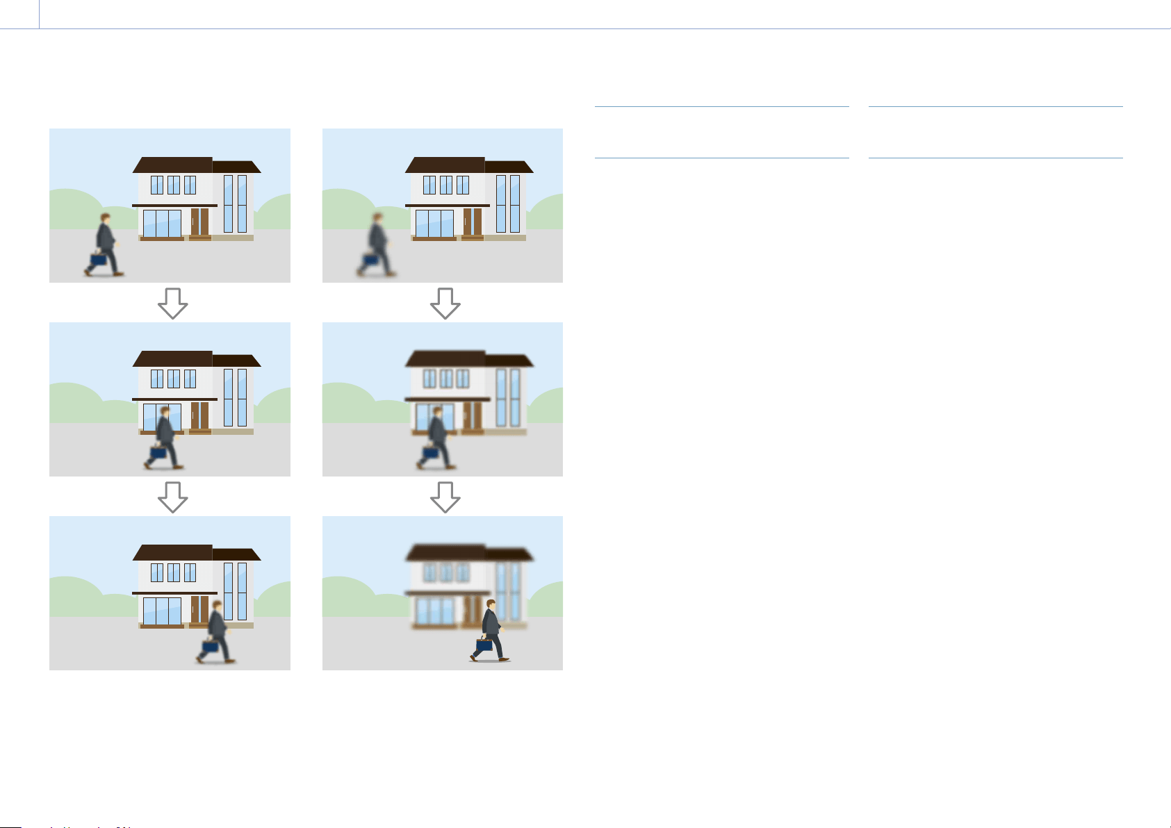
3. Shooting: Adjusting the Focus
33
AF Subj. Shift Sens.: 1 (Locked On) AF Subj. Shift Sens.: 5 (Responsive)
Change focus to another subject slowly Change focus to another subject rapidly
Changing the Focus Target
Manually (AF Assist)
When Focus >AF Assist (page 77) in the
Shooting menu is set to On, you can select the
target for auto focus during auto focus using
the focus ring on the lens.
Auto focus operation is restored when you
stop operating the focus ring.
Setting Focus >AF Subj. Shift Sens.
(page 77) in the Shooting menu to 1
(Locked On) is convenient when you want the
auto focus operation to continue as-is when
the focus position moves to a subject with a
different distance.
Using Manual Focus Temporarily
(Push Manual Focus)
Press the PUSH AUTO FOCUS button
(page 6) when in auto focus mode to
focus manually while the button is pressed.
The focus returns to auto focus when you
release the button.
This allows you to temporarily stop auto focus
and focus manually when something that is
not the subject of shooting crosses in front of
the subject.
[Tip]
The same operation is supported using an assignable
button (page 41) assigned with Push AF/Push MF.

3. Shooting: Adjusting the Focus
34
Using Auto Focus Temporarily
(Push Auto Focus)
When Focus >Push AF mode (page 77)
in the Shooting menu is set to AF, press the
PUSH AUTO FOCUS button (page 6) when
in manual focus mode to focus automatically
while the button is pressed.
Focusing occurs within the focus area set
using Focus >Focus Area (page 77) in the
Shooting menu.
The focus returns to manual focus when you
release the button.
This is useful when you want to move the
focus slowly from one subject to another
subject during manual focus.
[Tip]
The same operation is supported using an assignable
button (page 41) assigned with Push AF/Push MF.
[Note]
The Push Auto Focus function does not operate if the
lens is set for manual focusing.
Using Single-Shot Auto Focus
(Push Auto Focus (AF-S))
Set Focus >Push AF Mode (page 77) in
the Shooting menu to Single-shot AF(AF-S),
then set the focus area using Focus >Focus
Area(AF-S) (page 77) in the Shooting menu.
Press the PUSH AUTO FOCUS button when in
manual focus mode to focus automatically
at high speed. Focusing stops as soon as you
release the button.
The focus status is indicated by the focus
indicator.
On: The focus is fixed at the focus position.
Flashing: Out of focus. Since focusing is not
automatic, change the composition and
focus settings to achieve focus.
The focus returns to manual focus when you
release the button.
This is useful when you want to quickly focus
on a subject before starting to shoot.
[Tips]
The same operation is supported using an assignable
button (page 41) assigned with Push AF/Push MF.
You can also assign Focus Area(AF-S) to an assignable
button (page 41).
You can display/hide the focus area frame using
Display On/Off >Focus Area Ind.(AF-S) (page 92) in
the Monitoring menu.
During focus magnification, the focus adjusts to fit
the magnified display position.
[Notes]
The Push Auto Focus function does not operate if the
lens is set for manual focusing.
The focus area frame is not hidden when using the
DISPLAY button.
Focusing using Magnified View
(Focus Magnifier)
By factory default, the Focus Magnifier ×3/×6
function is assigned to the ASSIGN 4 button
on the grip remote control and the ASSIGN 10
button on the viewfinder (page 41).
Press the ASSIGN 4 button or ASSIGN 10
button to switch to the focus magnifier screen,
with the center magnified by approximately
three times. Press the button again to increase
the magnification to approximately six times.
This function is useful for checking the focus.
Press the button again to return to the normal
screen.
You can move the position to be magnified
during focus magnification using the arrow
buttons (page 7) or the multi selector
(page 9). You can return to the center by
pressing the SET button (page 7) or multi
selector.
When push auto focus (AF) is used during
focus magnification, focusing occurs within
the focus area set using Focus >Focus Area
(page 77) in the Shooting menu.
If push auto focus (AF-S) is used during
focus magnification, the focus adjusts to the
magnified display position.
[Notes]
The recorded image or SDI/HDMI output image is not
magnified when the focus is magnified.
During focus magnification, the STATUS button and
menu buttons are disabled.
The magnified position returns to the center of the
screen when the camcorder is turned off.
Focusing using Face Detection
(Face Detection AF)
The camcorder can detect people’s faces and
then adjust the focus on faces within the focus
area.
This function is available only when focus
adjustment is in AF mode or during push auto
focus.
When faces are detected, gray face detection
frames are displayed. The frames change to
white after auto focus is established. When
multiple individuals are detected, the main
subject is automatically determined.
[Tips]
When the focus area is set to Zone or Flexible
Spot and face detection frames overlap within the
specified focus area, the face detection frames
change to white, and the camcorder focuses on those
faces.
When push auto focus (AF-S) is used, the face
detection frames for the faces that are in focus
change to green.
Set the face detection AF action using Focus
>Face Detection AF (page 77) in the
Shooting menu.
Face Only AF:
The camera detects the faces of subjects
(people) and focuses only on their faces.
While a face is not detected, AF is temporarily
stopped (MF), and the Face Only AF mode auto
focus paused icon
(page 10) is displayed.
This mode is effective when you want to auto
focus on faces only.
Face Priority AF:
The camera detects the faces of subjects
(people) and prioritizes the focusing on the
faces. When a face is not detected, focusing is
in AF mode (default setting).

3. Shooting: Adjusting the Focus
35
Off:
The face detection AF function is disabled.
[Notes]
During push auto focus operation, Face Priority AF is
activated even if Face Only AF is currently selected.
When the FOCUS switch is set to MAN, face detection
AF is disabled (excluding during push auto focus
operation).
If you turn the camcorder off while Face Only AF is
selected, the mode automatically switches to Face
Priority AF when the camcorder is next turned on.
Hiding face detection frames
You can show/hide face detection frames
using Display On/Off >Face Detection Frame
(page 92) in the Monitoring menu.
[Note]
Green face detection frames are displayed for faces
that are in focus using push auto focus (AF-S), and are
not hidden using the DISPLAY button or when Face
Detection Frame is set to Off.
Focusing on a registered face
During face detection AF operation, you
can register a face for a subject (person) for
focusing on that face.
Only one face can be registered. Registering a
face overwrites the existing registration.
When a face is registered, the face detection
frame changes to a double frame (registered
face frame), and the registered face icon
(page 10) is displayed.
In face detection AF, the following actions
occur depending on the combination
of registered face and face detection AF
operating mode.
In Face Priority AF mode:
If the camera detects the registered face, the
camera focuses on that face. If the registered
face is not detected, face detection operation
continues.
In Face Only AF mode:
If the camera detects the registered face
only, the camera focuses on that face.
While the registered face is not detected,
AF is temporarily stopped (MF), and the
Face Only AF mode auto focus paused icon
(page 10) is displayed. This mode is
effective when you want to auto focus on the
registered person only.
Setting the registered face
Move the face selection cursor (orange
underline) to the face to register using the
arrow buttons (page 7) or multi selector
(page 9), and press the SET button
(page 7) or multi selector.
Other face
detection frames
(gray)
Registered face frame
(double white frame)
Face selection cursor (orange)
Clearing the registered face
Move the face selection cursor to the
registered face frame using the arrow buttons
(page 7) or multi selector (page 9),
and press the SET button (page 7) or multi
selector.
The registered face is cleared, the face
detection frame becomes a single frame, and
the registered face icon disappears.
When faces are detected with the registered
face frame not displayed and the face
selection cursor (orange) displayed, you can
clear the registered face by pressing the SET
button or multi selector twice.
[Notes]
Faces may not be detected depending on the
recording environment, condition of the subject, or
the settings.
You may not be able to get the proper effect, or
objects other than people’s faces may be detected as
a face, in some recording environments. In this case,
set the face detection AF function to Off.
Registration of the face of the intended individual for
focusing before shooting is recommended.
Face registration may not be successful depending
on hairstyle, facial decoration, or if not directly facing
the camera. In this case, the face detection frame may
become a double frame, but the registered face icon
is not displayed and the face is not registered.
If a face has already been registered, clearing the
existing face and then registering the new face is
recommended.
Switching face detection AF operation
using an assignable button
Assign Face Detection AF to an assignable
button (page 41). You can then switch
face detection AF operation in the order Face
Priority AF, Face Only AF, and Off each time
you press the button.
Setting using the direct menu
You can also set the face detection AF
operation using the direct menu (page 41).

3. Shooting
36
Adjusting the Brightness
ND
PRESET
ND
VARIABLE
ND ON
CLEAR
ND AUTO
STATUS FOCUS
IRIS
SHUTTER
L
M
H
WHT BALISO/GAIN
AUTO MAN
-
PUSH AUTO
PUSH AUTO
B
A
PRESET
B
C
D
E
F
G
I
J
A
You can adjust the brightness by adjusting the
iris, gain, shutter speed, and by adjusting the
light level using ND filters. You can also make
adjustments automatically.
The target level for automatic brightness
adjustment is set using Auto Exposure
(page 74) >Level in the Shooting menu.
You can also assign Auto Exposure Level to an
assignable button (page 41).
[Note]
The gain cannot be adjusted in Cine EI mode. The
base sensitivity is fixed. Also, the brightness cannot
be adjusted automatically using the shutter speed.
Brightness auto adjustment using the iris and ND filter
is supported.
Selecting the Base Sensitivity
You can select from two types of base
sensitivity on the camcorder.
In Custom mode, you can set Base Sensitivity
in the Shooting menu to High or Low. In Cine
EI mode, you can set Base ISO in the Shooting
menu to ISO 4000 or ISO 800.
You can shoot with good balance, without
increased noise, by selecting Low or ISO 800
in normal lighting conditions or selecting High
or ISO 4000 in low lighting conditions.
Adjusting the Iris
You can adjust the iris to adjust the brightness.
Adjusting the iris automatically
This function adjusts the brightness according
to the subject. A lens that supports auto iris is
required.
1 If a lens with Auto Iris switch is attached,
set the switch to AUTO.
2 Press and hold the IRIS function button (F)
to display the direct menu (page 41),
and select Auto.
[Tip]
You can also assign Auto Iris to an assignable
button (page 41).
[Note]
The iris cannot be adjusted automatically on an
A-mount lens.
Adjusting the iris manually
1 Press and hold the IRIS function button (F)
to display the direct menu (page 41),
and select Manual.
2 Press the IRIS function button (F) so that
the iris value is displayed on a white
background.
3 Turn the multi-function dial to adjust the
value.
[Tip]
You can also operate the multi-function dial as
an IRIS dial (page 41) by assigning the IRIS
function to the multi-function dial.
You can also assign the IRIS function to an
assignable dial (page 41).
Temporarily adjusting automatically
Press the PUSH AUTO IRIS button (E) to
automatically adjust the iris temporarily while
the button is pressed.
The iris returns to the previous setting when
you release the button.
[Tip]
You can also assign Push Auto Iris to an assignable
button (page 41).
[Note]
When the Auto Iris switch of the lens is set to MANUAL,
the Auto Iris and Push Auto Iris functions on the
camcorder have no effect. Manual iris adjustments on
the camcorder also have no effect.
Adjusting the Gain
In Custom mode, you can adjust the gain to
adjust the brightness.
Adjusting the gain automatically
Press and hold the ISO/GAIN function button
(I) to display the direct menu (page 41), and
select Auto.
[Tip]
You can also perform the same action by setting Auto
Exposure (page 74) >AGC in the Shooting menu
to On.
You can also assign AGC to an assignable button
(page 41).
Adjusting the gain manually
You can control the gain when you want to
adjust the exposure while using a fixed iris
setting or when you want to prevent the gain
increasing due to AGC.
1 Press and hold the ISO/GAIN function
button (I) to display the direct menu
(page 41), and select Manual.
2 Set the ISO/GAIN switch (J) to H, M, or L.
[Tip]
You can also assign Push AGC to an assignable button,
and set AGC to On temporarily by pressing and holding
the button.
Controlling the gain (fine adjustment)
1 Press the ISO/GAIN function button (I) so
that the gain value is displayed on a white
background.
2 Turn the multi-function dial to adjust the
value.

3. Shooting: Adjusting the Brightness
37
[Tip]
Change the gain preset value according to the ISO/GAIN
switch (J) setting.
Controlling the gain temporarily (fine
adjustment)
Turn the assignable dial (page 41) assigned
with the ISO/Gain/EI function, to adjust the
gain value set by the ISO/GAIN switch (J).
This is useful when you want to adjust the
exposure by one step without changing the
depth of field.
The adjusted gain value is canceled by
switching the ISO/GAIN switch (J), changing
the base sensitivity, setting AGC to On, or
turning the power off.
[Tip]
You can also assign this function to the multi-function
dial (page 41).
Adjusting the Exposure Index
In Cine EI mode, it is assumed that video
output with MLUT set to Off is recorded as the
main signal. By changing the brightness of
the image with MLUT On to match an EI value,
you can check the result of post-production
exposure sensitivity adjustment while
shooting.
You can change the EI value by setting the
ISO/GAIN switch (J) to H, M, or L.
[Tip]
You can change the EI value of each switch position
using ISO/Gain/EI >Exposure Index<H>/<M>/<L>
(page 73) in the Shooting menu.
Fine adjustment of the exposure index
1 Press the ISO/GAIN function button (I) so
that the EI value is displayed on a white
background.
2 Turn the multi-function dial to adjust the
value.
[Tip]
Change the EI preset value according to the ISO/GAIN
switch (J) setting.
Adjusting the Shutter
You can adjust the shutter to adjust the
brightness.
Adjusting the shutter automatically
Press and hold the SHUTTER function button
(G) to display the direct menu (page 41)
and select Auto to adjust the shutter speed or
shutter angle automatically in response to the
image brightness.
[Tip]
You can also perform the same action by setting Auto
Exposure (page 75) >Auto Shutter in the Shooting
menu to On.
Adjusting the shutter manually
1 Press and hold the SHUTTER function
button (G) to display the direct menu
(page 41), and select Speed or Angle.
2 Press the SHUTTER function button (G) so
that the shutter value is displayed on a
white background.
3 Turn the multi-function dial to adjust the
shutter speed.
[Tips]
To adjust the exposure time to match the frame
interval, select Off in step 1.
You can also set the angle and adjust the frequency
(page 73).
Adjusting the Light Level (ND
Filter)
In conditions where the lighting is too bright,
you can set the appropriate brightness by
changing the ND filter.
The camcorder features two ND filter modes.
You can switch between the two modes using
the ND PRESET/VARIABLE switch.
Adjusting in preset mode
Set the ND PRESET/VARIABLE switch (A) to
the PRESET position, and set the ND FILTER
POSITION up/down buttons (B) to one of the
following settings.
Clear: No ND filter
1: Transmittance set by ND Filter >Preset1
(page 73) in the Shooting menu.
2: Transmittance set by ND Filter >Preset2
(page 73) in the Shooting menu.
3: Transmittance set by ND Filter >Preset3
(page 73) in the Shooting menu.
Adjusting in variable mode
Set the ND PRESET/VARIABLE switch (A) to
the VARIABLE position. Switch the ND FILTER
POSITION up/down buttons (B) between
CLEAR and On.
Adjusting the light level automatically
You can set Auto ND Filter to On to enable
auto exposure adjustment using the ND filter.
1 Press the [+] button of the ND FILTER
POSITION up/down buttons (B) to turn ND
filter operation on.
2 Press and hold the ND VARIABLE AUTO
button (C) until Auto is selected.
Adjusting the light level manually
1 Press the [+] button of the ND FILTER
POSITION up/down buttons (B) to turn ND
filter operation on.
2 Press and hold the ND VARIABLE AUTO
button (C) until Manual is selected.
3 Turn the ND VARIABLE dial (D) to adjust
the transmittance of the filter.
[Tip]
You can also assign the ND Filter function to an
assignable dial (page 41).
Temporarily adjusting automatically
You can assign Push Auto ND to an assignable
button (page 41), and temporarily set Auto
ND Filter to On by pressing and holding the
button. Releasing the button sets Auto ND
Filter back to Off.
Press the [+] button of the ND FILTER POSITION
up/down buttons (B) to turn ND filter
operation on.
[Note]
When the ND filter is switched to or from CLEAR during
shooting, the ND filter frame is displayed on the image
and the operating sound is included in the audio.
[Tips]
You can set to CLEAR by turning the ND VARIABLE dial
(D) down from ND1/4. Turning the dial up from CLEAR
sets ND1/4. You can disable this action using ND Dial
>CLEAR with Dial (page 99) in the Technical menu.
You can also assign ND Filter Position to an assignable
button (page 41), and press the button instead of
using the ND FILTER POSITION up//down buttons to
change the setting.
Preset mode: Clear Preset1 Preset2 Preset3
Clear…
Variable mode: Clear On Clear…
You can also assign Auto ND Filter to an assignable
button (page 41), and press the button to switch
Auto ND filter between On and Off.
When shooting a brightly lit subject, closing the iris
too much may cause diffraction blur, producing an
image starting to go out of focus (typical phenomena
in video cameras). You can suppress this effect to
obtain better shooting results using the ND filter.

3. Shooting
38
ND
PRESET
ND
VARIABLE
ND ON
CLEAR
ND AUTO
STATUS FOCUS
IRIS
SHUTTER
L
M
H
WHT BALISO/GAIN
AUTO MAN
-
PUSH AUTO
PUSH AUTO
B
A
PRESET
H
K
You can select the adjustment mode to suit
the shooting conditions.
ATW (Auto Tracing White Balance)
This function adjusts the white balance
automatically to an appropriate level.
The white balance is automatically adjusted
when the color temperature of the light source
changes.
Press and hold the WHT BAL function button
(H) to display the direct menu (page 41)
and select ATW.
You can select the speed of adjustment
(five steps) using White Setting >ATW Speed
(page 76) in the Shooting menu.
[Tip]
You can freeze the current white balance setting by
assigning the ATW Hold function to an assignable
button (page 41), and pressing the assignable button
to temporarily pause ATW mode.
[Notes]
ATW cannot be used in Cine EI mode.
It may not be possible to adjust to the appropriate
color using ATW, depending on the lighting and
subject conditions.
Examples:
– When a single color dominates the subject, such as
sky, sea, ground, or flowers.
– When the color temperature is extremely high or
extremely low.
If the appropriate effect cannot be obtained because
the ATW auto tracking speed is slow or for other
reasons, run auto white balance.
Adjusting the White Balance
Manually
1 When white balance is set to ATW mode,
press and hold the WHT BAL function
button (H) to display the direct menu
(page 41), and select Manual.
2 Select B, A, or PRESET using the WHT BAL
switch (K).
B: Memory B mode
A: Memory A mode
PRESET: Preset mode
[Tip]
ATW can be enabled for memory B by setting White
Setting >White Switch<B> (page 76) in the Shooting
menu to ATW.
Memory A/Memory B mode
This mode adjusts the white balance to the
setting saved in memory A or B, respectively.
Preset mode
This mode adjusts the color temperature to a
preset value (factory default is 3200K).
Changing the default preset value
In preset mode, you can change an existing
preset value directly.
Press and hold the WHT BAL function button
(H) and select one of the following in the
direct menu.
Custom mode: 3200K, 4300K, 5600K,
6300K
Cine EI mode: 3200K, 4300K, 5500K
[Tip]
You can also assign Preset White Select to an assignable
button (page 41), and press the button to change the
setting.
Custom mode: 3200K 4300K 5600K 6300K
3200K…
Cine EI mode: 3200K 4300K 5500K 3200K…
Changing the color temperature
1 Press the WHT BAL function button (H) so
that the color temperature value is
displayed on a white background.
2 Turn the multi-function dial to adjust the
value.
[Tips]
In preset mode, you can set the value in 100K units.
In memory mode, you can set the value in 20K
units. You can also adjust the tint value using White
(page 76) >Tint in the Shooting menu.
Running auto white balance
The white balance to save in memory A/
memory B mode is configured automatically.
1 Select memory A mode or memory B
mode.
2 Place white paper (or other object) in a
location with the same lighting source
and conditions as the subject, then zoom
in on the paper to show white on the
screen.
3 Adjust the brightness.
Adjust the iris using the procedure in
“Adjusting the iris manually” (page 36).
4 Press the WB SET button (page 4).
If auto white balance is run in memory
mode, the adjustment value is saved in
the memory (A or B) selected in step 1.
If auto white balance is run in ATW
mode, the white balance adjustment
returns to the ATW mode white balance
when adjustment ends.
[Note]
If the adjustment is not successful, an error message is
displayed on the screen for about three seconds. If the
error message persists after repeated attempts to set
white balance, contact your Sony service representative.
Adjusting for Natural Colors (White Balance)

3. Shooting
39
You can specify the audio to be recorded
using the input connectors, switches, and dials
of the camcorder.
External audio input connectors and
selector switches
INPUT1 connector (page 8)
INPUT2 connector (page 8)
Multi-interface shoe (page 4)
CH1 INPUT select switch (page 7)
CH2 INPUT select switch (page 7)
INPUT1 (LINE/MIC/MIC+48V) switch
(page 4)
INPUT2 (LINE/MIC/MIC+48V) switch
(page 4)
Switches for setting the audio level
CH1 (AUTO/MAN) switch (page 7)
CH2 (AUTO/MAN) switch (page 7)
AUDIO LEVEL (CH1) dial (page 7)
AUDIO LEVEL (CH2) dial (page 7)
AUDIO LEVEL (CH3) dial (page 7)
AUDIO LEVEL (CH4) dial (page 7)
Selecting the Audio Input Device
1 Select the audio input connector.
For CH1/CH2, select the audio input using
the CH1 INPUT select switch or CH2 INPUT
select switch.
Set to EXT to use the INPUT1 connector or
INPUT2 connector.
If using a shoe microphone, XLR adaptor,
or UWP (UHF wireless microphone)
device, specify MI SHOE in the same way.
For details about the XLR adaptor, see
“Adding Audio Input Connectors”
(page 40).
For CH3/CH4, select the audio input using
Audio Input >CH3 Input Select
(page 95) and CH4 Input Select
(page 95) in the Audio menu.
[Tip]
For CH2, you can also select INPUT1 using Audio
Input >CH2 EXT Input Select (page 95) in the
Audio menu.
[Note]
The camcorder has a built-in narration microphone
for recording ambient sound. It can be used for
syncing the timing with other equipment. In such
cases, specify INT or Internal MIC.
2 Select the input audio source.
Set the INPUT1/INPUT2 (LINE/MIC/
MIC+48V) switches to the devices
connected to the INPUT1/INPUT2
connectors, respectively.
Connected device Switch position
External audio source (e.g.
mixer)
LINE
Dynamic microphone,
battery-operated
microphone
MIC
+48 V phantom power
feed microphone
MIC+48V
Selecting MIC+48V and connecting
a microphone that is not compatible
with a +48V source may damage the
connected device. Check the setting
before connecting the device.
If noise is a concern on connectors
with no device connected, set the
corresponding INPUT1/INPUT2 (LINE/
MIC/MIC+48V) switches to LINE.
Adjusting the Audio Recording
Level Automatically
Set the CH1/CH2 (AUTO/MAN) switches for the
channels to adjust automatically to AUTO.
For CH3/CH4, set Audio Input >CH3 Level
Control and CH4 Level Control in the Audio
menu to Auto (page 95).
Adjusting the Audio Recording
Level Manually
Use the following procedure to adjust the
audio recording level for CH1/CH2.
1 Set the CH1/CH2 (AUTO/MAN) switches for
the channels to adjust manually to MAN.
2 During shooting or standby, turn the
AUDIO LEVEL (CH1)/(CH2) dials of the
corresponding channels to adjust the
audio level.
For CH3/CH4, set Audio Input >CH3 Level
Control and CH4 Level Control in the
Audio menu to Manual, and then set the
audio recording level using the AUDIO
LEVEL(CH3)/(CH4) dials.
You can adjust the levels for CH1 to
CH4 as a group. You can adjust the
recording level using an assignable dial
(page 41) assigned with the Audio
Input Level function, or using Audio
Input >Audio Input Level in the Audio
menu.
[Tip]
The Audio Status screen is convenient for checking the
audio input level (page 13).
[Notes]
The Audio Input Level settings may be disabled,
depending on the combination of settings in
the Audio menu. For details, see the diagram on
page 131.
If either the CH1 INPUT select switch or CH2 INPUT
select switch is set to INT, CH2 is switched to
automatic/manual in conjunction with the CH1
(AUTO/MAN) switch. Also, the CH2 audio recording
level is set in conjunction with the AUDIO LEVEL (CH1)
dial.
The camcorder supports combinations of various
settings. For details, see the diagram on page 131.
Setting the Audio to Record

3. Shooting: Setting the Audio to Record
40
Adding Audio Input Connectors
You can connect up to four channels of XLR
audio devices to the camcorder at the same
time by using an XLR-K2M XLR adaptor
(not supplied) or XLR-K3M XLR adaptor (not
supplied).
Attach the XLR adaptor to the multi-interface
shoe, and set Audio Input >CH3 Input Select to
Shoe CH1 and CH4 Input Select to Shoe CH2 in
the Audio menu.
Camcorder functions that overlap will be
disabled for channels on which the XLR
adaptor is selected as the input. Use the
switches and dials on the XLR adaptor to
perform adjustments.
[Notes]
The camcorder does not support the digital audio
interface of the XLR-K3M.
If Audio Input >CH3 Level and CH4 Level in the Audio
menu are set to Audio Input Level, then Audio Input
Level on the camcorder will be set to match the level
adjusted on the XLR adaptor.
Audio Input Level is also enabled when the XLR
adaptor switch is set to AUTO.
When “Through” is specified, audio will be recorded at
the level adjusted with the XLR adaptor (page 132).
To attach an XLR-K2M XLR adaptor (not supplied) or
XLR-K3M XLR adaptor (not supplied) to the camcorder,
remove the microphone holder from the camcorder.

3. Shooting
41
Useful Functions
Direct Menu Operation
You can check the status and settings of the
camcorder displayed on the viewfinder screen,
and directly select and change the settings.
The following items can be configured.
Face Detection AF
Steady Shot
White Mode
Color Temp
Scene File
ND Filter Position / Auto ND Filter
ND Filter Value
Auto Iris
Iris Value
AGC
Gain Value
ISO Value
EI Gain Value
Auto Shutter
Shutter Value
Auto Exposure Mode
Auto Exposure Level
S&Q Motion Frame Rate
1 Press the multi-function dial, or an
assignable button assigned with the
Direct Menu function.
Only the items on the screen that can be
configured using the direct menu are
selectable using the orange cursor.
2 Turn the multi-function dial to move the
cursor to the menu item to operate, then
press the multi-function dial.
A menu is displayed or the item is
displayed on a white background.
3 Turn the multi-function dial to select a
setting, then press the multi-function dial.
The menu or white background
disappears and the new setting is
displayed with an orange cursor.
Press the assignable button assigned with
Direct Menu again or wait 3 seconds
without performing any action to exit the
direct menu.
[Tips]
Direct settings can also be configured by pressing
and holding each of the function buttons
(page 6).
When items are displayed on a white
background, the multi-function dial can be used
like an assignable dial.
The multi selector (page 9) can also be used
for selection operations.
Assignable Buttons/Dials
There are ten assignable buttons (page 6,
9) on the camcorder to which you can
assign functions.
You can also assign functions to the
assignable dial (page 9) on the grip
remote control and to the multi-function dial
on the camcorder.
Changing the button function
Use Assignable Button (page 82) in the
Project menu.
You can view the assigned functions on the
Assignable Button Status screen (page 14).
Functions assigned to each assignable button
by factory default
Button 1 S&Q Motion
Button 2 Off
Button 3 Off
Button 4 Focus Magnifier x3/x6
Button 5 Direct Menu
Button 6 Off
Button 7 Off
Button 8 Off
Button 9 Off
Button 10 Focus Magnifier x3/x6
Focus Hold button Focus Hold
Assignable functions
Off
Base ISO/Sensitivity
AGC
Push AGC
ND Filter Position
Auto ND Filter
Push Auto ND
Auto Iris
Push Auto Iris
Auto Shutter
Auto Exposure Level
Backlight
Spotlight
Preset White Select
ATW
ATW Hold
Focus Setting
Focus Area
Focus Area(AF-S)
Face Detection AF
Push AF Mode
Push AF/Push MF
Focus Hold
Focus Magnifier x3/x6
Focus Magnifier x3
Focus Magnifier x6
S&Q Motion
SteadyShot
Rec
Picture Cache Rec
Rec Review
Last Clip Del.
Shot Mark1
Shot Mark2
Clip Flag OK
Clip Flag NG
Clip Flag Keep
Color Bars
Tally [Front]
DURATION/TC/U-BIT
Display
Lens Info
Video Signal Monitor
Marker
VF Adjust
VF Mode
Gamma Display Assist
Peaking
Zebra
Thumbnail
Handle Zoom
NFC
Network Client Mode
Auto Upload (Proxy)
Direct Menu
User Menu
Menu
Changing the dial function
You can change the function of the multi-
function dial on the camcorder and the
assignable dial on the grip remote control.
For the multi-function dial, set using Multi
Function Dial (page 84) >Default Function in
the Project menu.
Off is assigned by factory default.
Functions assignable to the multi-function
dial
Off
IRIS
ISO/Gain/EI
Audio Input Level
[Note]
The setting is disabled while the menu is displayed.
For the assignable dial, set using Assignable
Dial (page 84) in the Project menu.
IRIS is assigned by factory default.
3. Shooting: Useful Functions
42
Functions assignable to the assignable dial
Off
ISO/Gain/EI
ND Filter
IRIS
Audio Input Level
You can view the assigned functions on the
Assignable Button Status screen (page 14).
Slow & Quick Motion
When the recording format (page 80) is set to the following values, you can specify different
values for the shooting frame rate and playback frame rate.
Recording format Frame rate
System frequency Imager scan mode Codec Video format
59.94/50 S35 4K XAVC-I 3840×2160P 1–60
1920×1080P 1–60
XAVC-L 3840×2160P 1–60
1920×1080P 1–60
FF 2K XAVC-I 1920×1080P 1–60, 100, 120
XAVC-L 1920×1080P 1–60, 100, 120
S35 2K XAVC-I 1920×1080P 1–60, 100, 120
XAVC-L 1920×1080P 1–60, 100, 120
29.97/25/23.98 FF 6K XAVC-I 3840×2160P 1–30
1920×1080P 1–30
XAVC-L 3840×2160P 1–30
1920×1080P 1–30
S35 4K XAVC-I 3840×2160P 1–60
1920×1080P 1–60
XAVC-L 3840×2160P 1–60
1920×1080P 1–60
FF 2K XAVC-I 1920×1080P 1–60, 100, 120
XAVC-L 1920×1080P 1–60, 100, 120
S35 2K XAVC-I 1920×1080P 1–60, 100, 120
XAVC-L 1920×1080P 1–60, 100, 120
You can turn Slow & Quick Motion mode
on/off by pressing an assignable button
(page 41) assigned with the S&Q Motion
function.
You can set the frame rate for shooting by
pressing and holding the button.
[Notes]
Slow & Quick Motion cannot be set during recording,
playback, or while the thumbnail screen is displayed.
Audio recording is not supported in Slow & Quick
Motion mode.
The auto focus function, auto iris function, and auto
shutter function are disabled in Slow & Quick Motion
mode.
Recording Video Intermittently
(Interval Rec)
The camcorder’s Interval Rec function allows
you to capture time-lapse video to the
camcorder’s internal memory. This function
is an effective way to shoot slow-moving
subjects.
When you start recording, the camcorder
automatically records a specified number of
frames at a specified interval time.
Shooting interval (Interval Time)
Number of frames in one take
(Number of Frames)
When Interval Rec is enabled, the HVL-LBPC
(option) video light automatically turns on
before recording starts, which allows you to
record pictures under stable light and color
temperature conditions (pre-lighting function).
[Notes]
Only one special recording function, such as Interval
Rec recording, can be used at any one time.
If another special recording mode is enabled while
Interval Rec is in use, Interval Rec is automatically
released.
Interval Rec mode is automatically released after
changing system settings, such as the video format.
Interval Rec settings cannot be changed during
recording or playback, or when the thumbnail screen
is displayed.

3. Shooting: Useful Functions
43
To set Interval Rec
Set Interval Rec (page 81) >Setting in
the Project menu to On, and set Number of
Frames and Interval Time.
If using the HVL-LBPC video light (option),
set the time interval for turning on the video
light before recording starts using Interval Rec
>Pre-Lighting in the Project menu, as required.
[Notes]
If you want to turn the video light on before the start
of recording, set the video light switch to AUTO. The
video light turns on and off automatically according
to the setting of Video Light Set (page 100) in the
Technical menu.
If you turn the video light switch on, the video
light is always lit (video light does not turn on/off
automatically).
If the video light is configured so that it will turn off
for a duration of 5 seconds or less, the video light
does not turn off.
The camcorder exits Interval Rec mode when
it is powered off, but the Number of Frames,
Interval Time, and Pre-lighting settings are
maintained. You do not need to set them
again the next time you shoot in Interval Rec
mode.
To shoot using Interval Rec
Press the record button to start recording.
“Int Rec” and “Int Stby” appear alternately
in the viewfinder.
If you are using the pre-lighting function, the
video light turns on before recording starts.
To stop shooting
Stop the recording.
When shooting ends, the video data stored
in memory up to that point is written to the
media.
To exit Interval Rec mode
Do one of the following.
Set the POWER switch to Off.
In recording standby mode, set Interval Rec
>Setting in the Project menu to Off.
Also, Interval Rec mode is automatically
released when the camcorder is restarted.
Limitations during recording
Audio is not recorded.
Reviewing the recording (Rec Review) is not
possible.
Genlock is not applied.
If the camcorder is turned off during
recording
If the POWER switch on the camcorder is set
to the Off position, the media is accessed for
several seconds to record the images stored
in memory up till that moment, and then
the power turns off automatically.
If power is lost because the battery
was removed, the DC power cord was
disconnected, or the power was turned off
from the AC adaptor, then the video and
audio data shot up to that point may be
lost (maximum 10 seconds). Care should be
exercised when exchanging the battery.
Recording Cached Pictures (Picture
Cache Rec)
The Picture Cache Rec function allows you
to capture video retroactively when you
start recording and then record it to XQD
memory cards by maintaining an internal
cache memory of a specified duration when
shooting. The picture cache recording time is
set using Picture Cache Rec >Cache Rec Time
(page 82) in the Project menu.
Supported recording formats
Codec Video
format
System
frequency
Cache
time
[sec.]
XAVC-I 3840×2160P 59.94 0–4 sec
50
29.97
25 0–4/
4–8 sec
23.98
1920×1080P 59.94 0–4/
4–8 sec
50
29.97 0–4/
4–8/
8–12/
12–16/
16–20/
20–24 sec
25
23.98 0–4/
4–8/
8–12/
12–16/
16–20/
20–24/
24–28 sec
Codec Video
format
System
frequency
Cache
time
[sec.]
XAVC-I 1920×1080i 59.94 0–4/
4–8/
8–12/
12–16/
16–20 sec
1920×1080i 50 0–4/
4–8/
8–12/
12–16/
16–20/
20–24 sec
XAVC-L 3840×2160P 59.94 0–4/
4–8/
8–12/
12–16 sec
50
29.97 0–4/
4–8/
8–12/
12–16/
16–20/
20–24/
24–28 sec
25
23.98
1920×1080P
50
59.94 0–4/
4–8/
8–12/
12–16/
16–20/
20–24/
24–28 sec
50
29.97
25
23.98
1920×1080P
35
59.94 0–4/
4–8/
8–12/
12–16/
16–20/
20–24/
24–28 sec
50
29.97
25
23.98

3. Shooting: Useful Functions
44
Codec Video
format
System
frequency
Cache
time
[sec.]
XAVC-L 1920×1080i
50
59.94 0–4/
4–8/
8–12/
12–16/
16–20/
20–24/
24–28 sec
50
1920×1080i
35
59.94 0–4/
4–8/
8–12/
12–16/
16–20/
20–24/
24–28 sec
50
1920×1080i
25
59.94 0–4/
4–8/
8–12/
12–16/
16–20/
20–24/
24–28 sec
50
MPEG
HD422
1920×1080i
50
59.94 0–4/
4–8/
8–12/
12–16/
16–20/
20–24/
24–28 sec
50
29.97
25
23.98
[Notes]
Picture Cache Rec cannot be set to On at the same
time as Interval Rec or Slow & Quick Motion. When
Picture Cache Rec is set to On, these other recording
modes are forcibly set to Off.
Picture Cache Rec mode cannot be selected while
recording or Rec Review is in progress.
When Picture Cache Rec is set to On, the timecode is
recorded in Free Run mode regardless of the setting
in the TC/Media menu (page 90).
The Output Format setting may not be configurable in
Picture Cache Rec mode. If this occurs, temporarily set
Picture Cache Rec to Off, and then change the setting.
Configuring before shooting
Configure Picture Cache Rec (page 82) in
the Project menu before shooting.
You can also assign the Picture Cache Rec
function to an assignable button (page 41)
and switch Picture Cache Rec >Setting
between On and Off using the button.
When configured, the “” ( is green)
indicator appears in the viewfinder.
Starting picture cache recording
When you press the record button, recording
starts and video is written to XQD memory
cards starting from the video stored in the
cache memory.
To cancel Picture Cache Rec
Set Picture Cache Rec >Setting in the Project
menu to Off, or press an assignable button
assigned with the Picture Cache Rec function.
[Notes]
Changing the recording format clears the video in
cache memory stored up to that point, and starts
caching new video. Consequently, picture cache
recording of pictures before changing format is not
possible, even if you start recording immediately after
changing format.
If Picture Cache Rec is set to On or Off immediately
after inserting an XQD memory card, cache data may
not be recorded on the card.
Video is stored in cache memory when the Picture
Cache Rec function is set to On. Video prior to the
function being set to On is not cached.
Video is not stored in cache memory while an XQD
memory card is being accessed, such as during
playback, Rec Review, or thumbnail screen display.
Picture cache recording of video during that interval
is not possible.
Recording to Memory Cards A and
B Simultaneously (2-slot Simul
Rec)
You can record to both memory card A and
memory card B simultaneously by setting
Simul Rec >Setting in the Project menu to On.
[Note]
Simultaneous recording is not supported in Slow &
Quick Motion mode (page 77) or Picture Cache
Rec mode (page 82). Also, simultaneous recording
is not supported for the following recording formats
(page 80).
XAVC-I
3840×2160 59.94P, 3840×2160 50P,
3840×2160 29.97P, 3840×2160 25P,
3840×2160 23.98P
XAVC-L
3840×2160 59.94P, 3840×2160 50P,
3840×2160 29.97P, 3840×2160 25P,
3840×2160 23.98P
Changing the Settings of the
Record START/STOP Buttons on
the Camcorder and Handle
When simultaneous recording (Simul Rec) is
enabled, you can start/stop recording to each
memory card independently using the record
START/STOP buttons on the camcorder and
the handle.
By factory default, both buttons are set to
start/stop simultaneous recording to both
memory cards A and B.
“Rec Button [SlotA SlotB] Handle Rec Button
[SlotA SlotB]”
When the buttons are set to control recording
for different memory cards, SDI/HDMI Rec
Control follows the recording state of slot A.
To change the setting
Select Simul Rec >Rec Button Set in the Project
menu.
Rec Button Set Buttons and memory
cards
“Rec Button [SlotA
SlotB] Handle Rec
Button [SlotA SlotB]”
Starts/stops
simultaneously
recording to memory
cards A and B using
either button.
“Rec Button [SlotA]
Handle Rec Button
[SlotB]”
The record START/STOP
button starts/stops
recording to memory
card A, and the record
START/STOP button on
the handle starts/stops
recording to memory
card B.
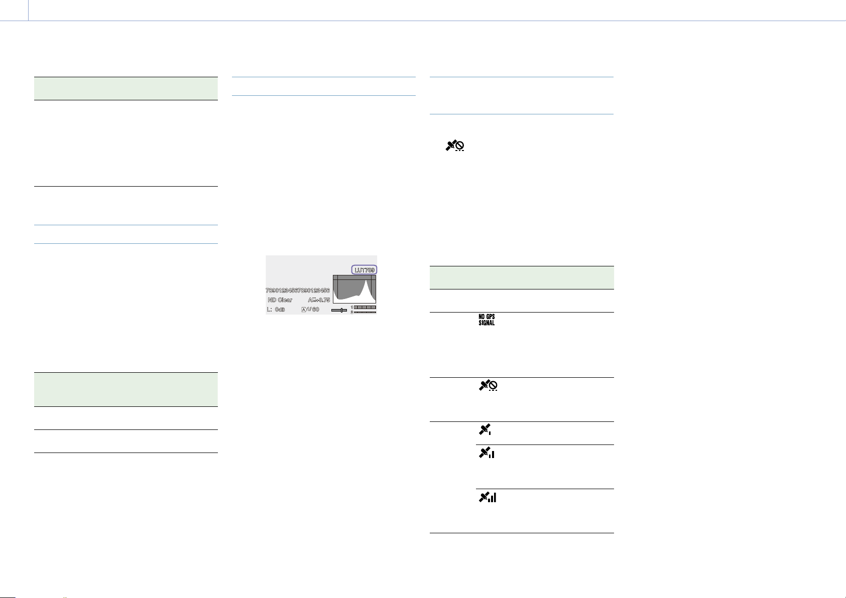
3. Shooting: Useful Functions
45
Rec Button Set Buttons and memory
cards
“Rec Button [SlotB]
Handle Rec Button
[SlotA]”
The record START/STOP
button starts/stops
recording to memory
card B, and the record
START/STOP button on
the handle starts/stops
recording to memory
card A.
4K & HD (Sub) Recording
You can simultaneously record a 4K (QFHD)
video as a main clip and an MPEG HD422
video as a sub-clip, which can be used for
editing, to a single XQD memory card.
The following XQD memory card recording
formats can be used for 4K & HD (Sub)
recording.
The sub-clip recording format varies,
depending on the system frequency of the
main clip.
Main clip
recording
format
System
frequency
Sub-clip
recording
format
XAVC-I
3840×2160P
29.97/25/
23.98
MPEG HD422
1920×1080P
XAVC-L
3840×2160P
59.94/50 MPEG HD422
1920×1080i
[Tip]
Sub-clips can be copied to other media as main clips
using Copy Sub Clip (page 97) in the Thumbnail
menu.
Video Signal Monitor
You can set the type of video signal to display
on the viewfinder screen to waveform,
vectorscope, or histogram using Display On/
Off >Video Signal Monitor (page 93) in the
Monitoring menu.
Monitoring target display
In Cine EI mode, the color space setting
(page 24) or monitor LUT setting
(page 78) information is displayed at
the top right of the video signal monitor to
indicate the target of monitoring.
Obtaining Location Information
(GPS)
When GPS in the Technical menu is set to
On,
is displayed when the camcorder is
seeking GPS satellites. When positioning is
established, location information is recorded
when shooting video.
[Notes]
The GPS setting in the Technical menu cannot be set
to On when the handle is not attached, as the GPS
receiver is built into the handle.
The icon displayed varies, depending on the signal
reception from the GPS satellites.
While using the GPS function, gripping the handle
may affect the positioning accuracy.
Positioning
status
Display GPS reception state
Off No
display
GPS is set to Off or an
error occurred.
Positioning
not
available
Location information
could not be obtained
because GPS signal
could not be received.
Move to a location with
a clear view of the sky.
Searching
for
satellites
Searching for GPS
satellites. Several
minutes may be required
to acquire satellites.
Positioning
A weak GPS signal is
being received.
A GPS signal is being
received. Location
information can be
acquired.
A strong GPS signal is
being received. Location
information can be
acquired.
[Tips]
GPS is set to On by factory default. Location and
time information of video shot when positioning is
enabled is recorded by the camcorder.
If a positioning icon is not displayed after several
minutes, there may be a problem with signal
reception. Start shooting without location information,
or move to an area with a clear view of the sky.
Shooting when a positioning icon is not displayed
means that location information will not be recorded.
The GPS signal may not be received when indoors or
near tall structures. Move to a location with a clear
view of the sky.
The recording of location information may be
interrupted, depending on the strength of the
received signal, even if a positioning icon is displayed.

3. Shooting: Useful Functions
46
Planning Metadata
Planning metadata is information about
shooting and recording plans recorded in an
XML file.
You can shoot using clip names and shot
mark names defined in advance in a planning
metadata file.
You can send and receive planning metadata
via a network using the “Content Browser
Mobile” application.
[Notes]
When the media slot cover is opened, the transfer
of planning metadata via the network is interrupted.
Planning metadata cannot be transferred while the
cover is open. The transfer resumes when the cover
is closed.
To define clip names or shot mark names, use a
font set for the language specified using Language
>Select (page 107) in the Maintenance menu. Text
characters may not be displayed correctly if you use a
language that is different from the language setting
of the camcorder.
If you define clip and shot mark names in French,
Dutch, or Finnish, some characters are displayed in a
different but similar font.
Loading a planning metadata file
To record planning metadata together with
clips, it is necessary to load a planning
metadata file into the camcorder’s memory
beforehand.
Insert the XQD memory card with the planning
metadata file (.xml) saved to the directory
below into the camcorder card slot, then select
and load the file using Planning Metadata
(page 85) >Load Media(A) or Load Media(B)
in the Project menu.
exFAT: XDROOT/General/Sony/Planning
Confirming the detailed information in
planning metadata
After loading planning metadata into the
camcorder, you can check the detailed
information that it contains, such as file
names, date and time of creation, and titles.
Select Planning Metadata (page 85)
>Properties >Execute in the Project menu.
Clearing the loaded planning metadata
You can clear the planning data loaded in the
camcorder memory.
Select Planning Metadata (page 85) >Clear
Memory >Execute in the Project menu.
Defining a clip name in planning
metadata
The following two types of clip name strings
can be written in a planning metadata file.
ASCII-format name that is displayed on the
viewfinder screen
UTF-8 format name that is actually
registered as the clip name
When you specify a clip name in planning
metadata, the name is displayed under the
operation status indication on the viewfinder
screen.
Example of clip name strings
Use a text editor to modify the description for
the planning metadata <Title> tag.
The shaded fields in the example are clip
name strings.
“Typhoon” is described in ASCII format (up to
44 characters). “Typhoon_Strikes” is described
in UTF-8 format (up to 44 bytes).
“
sp
” indicates a space and indicates a
carriage return.
<?xml
sp
version="1.0"
sp
encoding="
UTF-8"?>
<PlanningMetadata
sp
xmlns="http://
xmlns.sony.net/pro/metadata/
planningmetadata"
sp
assignId="
P0001"
sp
creationDate="
2011-08-20T17:00:00+09:00"
sp
lastUpdate="
2011-09-28T10:30:00+09:00"
sp
version="1.00">
<Properties
sp
propertyId="
assignment"
sp
update="
2011-09-28T10:30:00+09:00"
sp
modifiedBy="Chris">
<Title
sp
usAscii="Typhoon"
sp
xml:lang="en">Typhoon_Strikes
</Title>
</Properties>
</PlanningMetadata>
[Notes]
When you create a file, enter each statement as a
single line by breaking a line with a carriage return
only after the last character of the line, and do not
enter spaces except where specified with “
sp
.”
A string of up to 44 bytes (or 44 characters) is valid as
a clip name.
If the UTF-8 format string exceeds 44 bytes, the first
44 bytes are used as the clip name.
If only a string in ASCII format is specified, the ASCII
format name up to the 44th character is used as the
clip name.
When neither the ASCII format name string nor
UTF-8-format name string is valid, a clip name in the
standard format is used.
The following characters cannot be used in clip
names, and are replaced by an underscore character
(_).
Invalid characters: “*/:<>?\|
Using a clip name defined in planning
metadata
Load a planning metadata file that contains
the clip name into the memory of the
camcorder, then select Clip Name Format
>Auto Naming (page 90) >Plan in the TC/
Media menu.
Clip names are generated by adding an
underscore (_) and a 5-digit serial number
(00001 to 99999).
Example: Typhoon_Strikes_00001, Typhoon_
Strikes_00002, …
[Notes]
If the serial number reaches 99999, it returns to 00001
upon the next recording.
When you load another planning metadata file, the
5-digit serial number returns to 00001.
Defining shot mark names in planning
metadata
When you record shot mark 1 or shot mark 2,
you can apply a name to the shot mark, using
a string defined in planning metadata.
Example of shot mark name strings
Use a text editor to modify the description for
the planning metadata <Meta name> tag.
The shaded fields in the example are shot
mark name strings.
Names can be either in ASCII-format (up
to 32 characters) or UTF-8-format (up to 16
characters).
“
sp
” indicates a space and indicates a
carriage return.
[Note]
If a name string contains even one non-ASCII character,
the maximum length of that string is limited to 16
characters.
<?xml
sp
version="1.0"
sp
encoding="
UTF-8"?>
<PlanningMetadata xmlns="http://
xmlns.sony.net/pro/metadata/
planningmetadata"
sp
assignId="
H00123"
sp
creationDate="
2011-04-15T08:00:00Z"
sp
lastUpdate="
2011-04-15T15:00:00Z"
sp
version=
"1.00">
<Properties
sp
propertyId=
"assignment"
sp
class="original"
sp
update="2011-04-15T15:00:00Z"
sp
modifiedBy="Chris">
<Title
sp
usAscii="Football
Game"
sp
xml:lang="en">
Football Game 15/04/2011
</Title>
<Meta
sp
name="_ShotMark1"
sp
content="Goal"/>
<Meta
sp
name="_ShotMark2"
sp
content="Shoot"/>
</Properties>
</PlanningMetadata>

3. Shooting: Useful Functions
47
[Note]
When you create a file, enter each statement as a single
line by breaking a line with a carriage return only after
the last character of the line, and do not enter spaces
except where specified with “
sp
” outside the shot mark
name strings.

3. Shooting
48
Proxy Recording
You can record proxy data to an SD card at the
same time as recording to an XQD memory
card.
For details about supported SD cards, formatting SD cards,
and checking the remaining capacity, see “Using a UTILITY
SD/MS Card” (page 28).
Configuring Before Shooting
1 Set Proxy Rec >Setting in the Project menu
to On.
2 Insert the SD card into the UTILITY SD/MS
card slot (page 8) with the label facing
right.
[Note]
Proxy Rec cannot be set to On at the same time as S&Q
Motion, Interval Rec, Picture Cache Rec, 2-slot Simul Rec,
or 4K & HD (Sub) Rec. When Proxy Rec is set to On, these
other recording modes are forcibly set to Off.
Recording a Proxy
Press the record button to start the recording
after completing the required setting for
shooting.
[Notes]
If the camcorder is turned off or the SD card is
removed while the SD card is being accessed, the
integrity of data on the card cannot be guaranteed.
All data recorded on the card may be discarded.
Always make sure the access indicator is off before
turning off the camcorder or removing the SD card.
Take caution to prevent the SD card from flying out
when inserting/ejecting the card.
To exit, stop the recording.
When the recording on an XQD memory
card is stopped, proxy data recording is also
stopped.
Changing Proxy Recording
Settings
Setting the picture size
Select Proxy Rec >Proxy Format (page 81) in
the Project menu, and set the picture size.
Setting the audio channel
Select Proxy Rec >Audio Channel (page 81)
in the Project menu, and set the audio channel
for proxy data recording.
About the Recorded File
The file name extension is “.mp4”.
The timecode is also recorded simultaneously.
Storage Destination of the
Recorded File
The recorded file is stored in the “/PRIVATE/
PXROOT/Clip” directory.
About the File Name
The file name consists of the clip name
recorded on the XQD memory card and a
consecutive number suffix.
In 2-slot Simul Rec mode, the clip name of slot
A has precedence.
The consecutive number is maintained even if
the camcorder is turned off. The consecutive
number returns to 0001 by executing All Reset.
For details about clip names, see Clip Name
Format (page 90) in the TC/Media menu.

49
4. Network Functions
Connecting to Other Devices via LAN
The camcorder can connect to smartphones,
tablets, and other devices via LAN connection.
Making a LAN connection between a device
and the camcorder enables the following
using the web remote control (page 58) or
“Content Browser Mobile” application.
Planning metadata (page 46)
Send and receive planning metadata using a
device and camcorder.
You can send planning metadata created
beforehand to the camcorder to specify clip
names.
Remote operation via LAN
You can control the camcorder from a
smartphone, tablet, or computer that is
connected to the camcorder via a LAN.
File transfer via LAN
You can transfer a proxy file (low resolution)
that is recorded on an SD card in the
camcorder or original file (high resolution)
that is recorded by the camcorder to the
server via a LAN.
Video monitoring via LAN
You can create a stream (H.264) from the
camera or playback video of the camcorder,
and monitor the video using the “Content
Browser Mobile” application from a device
via a LAN.
“Content Browser Mobile” application
You can operate the camcorder remotely on
the device screen while monitoring the video
from the camcorder, and configure settings
of the camcorder, using the “Content Browser
Mobile” application.
For details about the “Content Browser Mobile” application,
contact your Sony sales or service representative.
Streaming high quality video using Sony
QoS technology (page 56)
You can stream high quality video using a
Sony Network RX Station (sold separately)
or XDCAM air* Connection Control Manager
(CCM) connected with the camcorder in
network client mode.
* XDCAM air is a cloud service that is provided by Sony.
To use this service, registration is required.
XDCAM air is not provided in some regions. For details
on areas where the service is provided, refer to the
following site.
https://www.xdcam-air.com
In addition, refer to the following sites for the privacy
policy of XDCAM air.
– Terms of service
https://www.xdcam-air.com/site/tos_eu.html
– Privacy policy of XDCAM air
https://sony-imaging-productssolutions.co.jp/pp/
sips/en/index.html
– Privacy policy of professional ID
https://www.pro-id.sony.net/#/privacyPolicy
For more details, contact a Sony professional sales
representative.
Setting the User Name and
Password
Set the user name and password of the
camcorder in order to use the network
function.
1 Set Access Authentication >User Name
(page 102) in the Network menu.
2 Set Access Authentication >Password
(page 102) in the Network menu.
Connecting using Wireless LAN
Access Point Mode
The camcorder works as an access point, and
connects to a device via a wireless LAN.
Smartphone/
tablet
Computer
Connecting to an NFC-compatible device
with one-touch operation
Devices that support NFC can be connected
(one-touch connection) using NFC.
1 Open [Settings] on the device, select
[More], and place a check mark in the NFC
checkbox.
2 Turn the camcorder on.
3 Activate the NFC function.
Press and hold (for 3 seconds) an
assignable button assigned with NFC or
select Wireless LAN >NFC in the Network
menu to activate NFC connection mode.
The NFC function is available only while
appears on the screen.
4 Touch the camcorder using the device.
The device connects to the camcorder
and “Content Browser Mobile” starts.
[Notes]
Disable sleep mode and screen lock beforehand.
Touch and hold the device still until the “Content
Browser Mobile” application launches (1 to 2
seconds).
Connecting to a WPS-compatible device
Devices that support WPS can be connected
using WPS.
1 Select Wireless LAN >Setting >Access
Point Mode in the Network menu.
2 Select Wireless LAN >WPS >Execute in the
Network menu.
3 Open the device Network settings or Wi-Fi
settings on the device, and turn Wi-Fi on.
4 Select the camcorder SSID from the SSID
list in Wi-Fi Network on the device, then
select WPS Push Button in Option on the
device to connect.
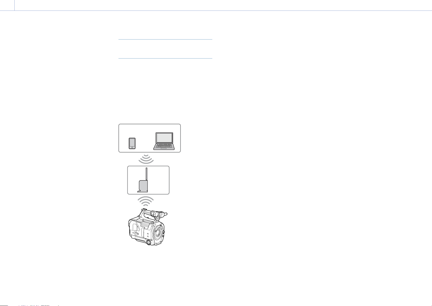
4. Network Functions: Connecting to Other Devices via LAN
50
[Notes]
The operation method differs depending on the
device.
For the SSID and password of the camcorder,
check AP Mode Settings >Camera SSID &
Password (page 102) in the Network menu.
5 Display the web remote control
(page 58). Or connect using the
Content Browser Mobile application.
Connecting by inputting an SSID and
password on a device
You can connect the camcorder to a device by
entering the SSID and password on a device.
1 Select Wireless LAN >Setting >Access
Point Mode in the Network menu.
2 Open the device Network settings or Wi-Fi
settings on the device, and turn Wi-Fi on.
3 Connect the device to the camcorder by
selecting the camcorder SSID from the
SSID list in Wi-Fi Network and entering the
password.
For the SSID and password of the
camcorder, check AP Mode Settings
>Camera SSID & Password (page 102) in
the Network menu.
[Note]
The operation method differs depending on the
device.
4 Display the web remote control
(page 58). Or connect using the
Content Browser Mobile application.
Connecting using Wireless LAN
Station Mode
The camcorder connects to an existing access
point of the wireless LAN as a client. The
camcorder and device connect via the access
point.
The 10 most recently connected access points
are displayed in the history.
The connection history is saved in an ALL
file, but the access passwords are not saved.
Password entry is required the next time you
connect after loading the ALL file.
Smartphone/
tablet
Access
point
Computer
Connecting to an access point using
WPS
If the access point is compatible with the WPS
function, you can connect to the access point
with simple settings.
1 Turn the access point on.
2 Turn the camcorder on.
3 Select Wireless LAN >Setting > Station
Mode in the Network menu.
4 Select Wireless LAN >WPS >Execute in the
Network menu.
5 Press the WPS button of the access point.
For details about the operation of the
WPS button, refer to the operating
instructions of the access point.
When the connection is successful, the
network status indicator icon will show a
strength of 1 or higher on the viewfinder
screen.
[Note]
If the connection fails, perform steps from step 1
again.
6 Connect the device to the access point.
For details about connecting, refer to the
operating instructions of the device.
7 Display the web remote control
(page 58). Or connect using the
Content Browser Mobile application.
Connecting to an access point using
auto network detection or manually
You can configure connection to a desired
access point from the setup menu.
You can configure connection to a desired
access point using the auto network detection
function.
Connecting using the network auto detection
function
1 Perform steps 1 to 3 in “Connecting to an
access point using WPS” (page 50).
2 Select ST Mode Settings >Scan Networks
(page 103) >Execute in the Network
menu.
The camcorder starts detection of
connection destinations.
Possible destinations that are found are
displayed in a list.
3 Select a destination from the list.
The network (access point) details screen
appears. The selected connection is
displayed in SSID.
4 Select Password, and set the password on
the password input screen.
Selecting an SSID in the connection
history automatically configures settings,
including the password.
Set the password to return to the network
(access point) details screen.
5 Configure the following connection
settings.
DHCP
Set the DHCP setting.
When you set to On, the IP address is
assigned to the camcorder automatically.
To assign the IP address to the
camcorder manually, set to Off.
IP Address
Enter the IP address of the unit.
This setting is available only when DHCP
is set to Off.
Subnet Mask
Enter the subnet mask of the unit.
This setting is available only when DHCP
is set to Off.

4. Network Functions: Connecting to Other Devices via LAN
51
Gateway
Enter the gateway for the access point.
This setting is available only when DHCP
is set to Off.
DNS Auto
Sets whether to acquire DNS
automatically.
When set to On, the DNS server address
is automatically acquired. This setting is
available only when DHCP is set to On.
Primary DNS Server
Enter the primary DNS server for the
access point.
This setting is available only when DNS
Auto is set to Off.
Secondary DNS Server
Enter the secondary DNS server for the
access point.
This setting is available only when DNS
Auto is set to Off.
6 When finished, select Connect to connect
to the access point.
Connecting manually
1 Perform steps 1 to 3 in “Connecting to an
access point using WPS” (page 50).
2 Select ST Mode Settings >Manual Register
(page 103) >Execute in the Network
menu.
Momentarily, the network (access point)
details screen appears.
3 Configure the following connection
settings.
SSID
Enter the SSID for the connection access
point.
Security
Select the encryption method.
Password
Enter the password for the connection
access point.
DHCP
Set the DHCP setting.
When you set to On, the IP address is
assigned to the camcorder automatically.
To assign the IP address to the
camcorder manually, set to Off.
IP Address
Enter the IP address of the unit.
This setting is available only when DHCP
is set to Off.
Subnet Mask
Enter the subnet mask of the unit.
This setting is available only when DHCP
is set to Off.
Gateway
Enter the address of the gateway.
This setting is available only when DHCP
is set to Off.
DNS Auto
Sets whether to acquire DNS
automatically.
When set to On, the DNS server address
is automatically acquired. This setting is
available only when DHCP is set to On.
Primary DNS Server
Enter the address of the primary DNS
server.
This setting is available only when DNS
Auto is set to Off.
Secondary DNS Server
Enter the address of the secondary DNS
server.
This setting is available only when DNS
Auto is set to Off.
4 When finished, select Connect to connect
to the access point.
Connecting to a Device using a
LAN Cable
You can connect with a device by connecting
the wired LAN connector of the XDCA-FX9
(page 23) attached to the camcorder to a
LAN switch using a LAN cable.
Computer
LAN switch
LAN cable connections and wired LAN
settings
1 Connect the wired LAN connector of the
XDCA-FX9 to a LAN switch using a LAN
cable.
2 Turn the camcorder on.
3 Set Wired LAN >Setting (page 104) in the
Network menu to On.
4 Configure connection settings using
Wired LAN >Detail Settings (page 104) in
the Network menu.
DHCP
Set the DHCP setting.
When you set to On, the IP address is
assigned to the camcorder automatically.
To assign the IP address to the
camcorder manually, set to Off.
IP Address
Enter the IP address of the unit.
This setting is available only when DHCP
is set to Off.
Subnet Mask
Enter the subnet mask of the unit.
This setting is available only when DHCP
is set to Off.
Gateway
Enter the address of the gateway.
This setting is available only when DHCP
is set to Off.
DNS Auto
Sets whether to acquire DNS
automatically.
When set to On, the DNS server address
is automatically acquired. This setting is
available only when DHCP is set to On.
Primary DNS Server
Enter the address of the primary DNS
server.
This setting is available only when DNS
Auto is set to Off.
Secondary DNS Server
Enter the address of the secondary DNS
server.
This setting is available only when DNS
Auto is set to Off.
5 When finished, select Set to apply the
settings.
[Note]
Always select Set after changing the connection
settings. The settings are not applied if Set is not
selected.
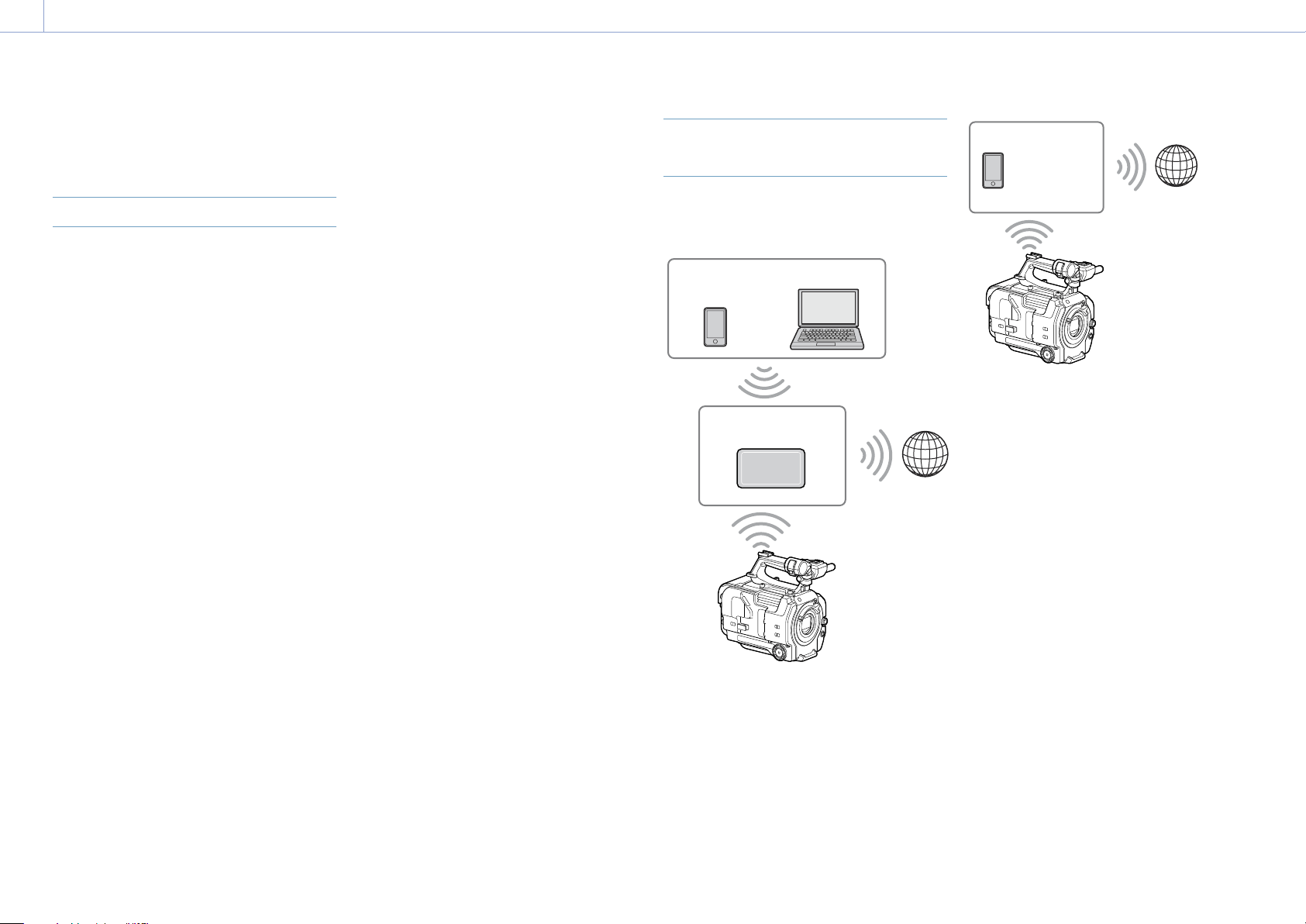
4. Network Functions
52
You can connect the camcorder to the Internet
using a modem, wired LAN, or wireless LAN.
Connecting using a Modem
You can connect the camcorder to the Internet
via a 3G/4G network by attaching an XDCA-
FX9 (page 23) to the camcorder and an
optional modem to the XDCA-FX9.
Attaching and using more than one modem
at the same time enables high-quality
streaming in network client mode, using two
lines for higher quality streaming and device
redundancy.
For details about compatible modems,
contact your Sony dealer or a Sony service
representative.
[Note]
A modem cannot be used at the same time as a wired
LAN.
Attaching an XDCA-FX9 to the unit
Attach a modem that supports the USB
standard to the USB 2.0 (HOST) connector
of the XDCA-FX9. Two modems can be used
simultaneously by connecting modems to
both connectors.
[Note]
Attach/remove the modem while the camcorder is
turned off.
Connecting to a network
1 Turn the camcorder on.
2 Set Modem >Setting in the Network menu
to On.
[Note]
It may take some time (about 1 minute) to connect
to a 3G/4G network. Wait until the network status
indicator (page 10) modem icon shows a
strength of 1 or higher on the viewfinder screen.
Connecting using Wireless LAN
Station Mode
You can connect the camcorder to the Internet
in Wi-Fi station mode via an optional wireless
LAN router or by tethering to a device.
Smartphone/
tablet
Wireless LAN
router
Computer
Internet
Smartphone/
tablet
Internet
Connect to the wireless LAN router or device
as described in “Connecting using Wireless
LAN Station Mode” (page 50).
Connecting to the Internet

4. Network Functions: Connecting to the Internet
53
Connecting using a LAN Cable
You can connect with a device by connecting
the wired LAN connector of the XDCA-FX9
(page 23) attached to the camcorder to an
Internet router using a LAN cable.
Computer
Router
Internet
Connect to the Internet router as described in
“Connecting to a Device using a LAN Cable”
(page 51).

4. Network Functions
54
Uploading Files
You can upload a proxy file or original file that
is recorded on the camcorder to a server on
the Internet or a server on a local network via
a 3G/4G network or access point.
[Note]
When the media slot cover is opened, the transfer of
files via the network is interrupted. Files cannot be
transferred while the cover is open. The transfer resumes
when the cover is closed.
Preparations
Connecting to a network
Connect the camcorder to the Internet or local
network as described in “Connecting to the
Internet” (page 52) or “Connecting to Other
Devices via LAN” (page 49).
Registering a file transfer destination
Register the server for uploading in advance.
1 Select File Transfer >Server Settings1 (or
Server Settings2, Server Settings3) in the
Network menu.
The transfer destination setup screen
appears.
2 Set each item on the transfer destination
setup screen.
Display Name
Enter the name of the server to display in
the transfer destination list.
Service
Displays the server type.
“FTP”: FTP server
Host Name
Enter the address of the server.
Port
Enter the port number of the server to
connect.
User Name
Enter the user name.
Password
Enter the password.
Passive Mode
Turn passive mode on/off.
Destination Directory
Enter the name of the directory on the
destination server.
[Notes]
When editing, “” indicates characters that
cannot be changed. Correct operation is not
guaranteed when editing a directory name that
contains these characters.
If you need to edit, delete all the characters and
re-enter a value.
If characters that are invalid on the destination
server are entered in Destination Directory, files
will be transferred to the user’s home directory.
Invalid characters will vary depending on the
server.
Using Secure Protocol
Set whether to perform secure FTP
uploading.
Root Certificate
Load/clear a certificate.
Load
Select Set in step 3 to import a CA
certificate.
* The certificate to be loaded must be in PEM
format, and should be written to the root
directory of the Utility SD card with “certification.
pem” file name.
Clear
Select Set in step 3 to clear a CA
certificate.
None
Do not load or clear a certificate.
[Notes]
Set the clock of the camcorder to the correct time
before importing a CA certificate.
When recording in XAVC-I 3840×2160P 59.94/50P,
Load cannot be selected.
In low voltage state, Load/Clear cannot be
selected for a CA certificate.
Root Certificate Status
Displays the load status of the certificate.
Reset
Reset the settings of Server Settings to
the defaults.
3 When finished, select Set to apply the
settings.
Always select Set after changing the
settings. The settings are not applied if
Set is not selected.
You can also register a server using the web
remote control “Registering a destination
server” (page 59).
Selecting a File and Uploading
Upload a file that is recorded on an SD card
or an original file that is recorded on an XQD
memory card to a server.
Files can also be uploaded via web remote
control. For details, see “Transferring files (Slot
A, Slot B, Slot SD/MS)” (page 60).
Uploading a proxy file on an SD card
from the thumbnail screen
1 Connect the camcorder and device using
a LAN connection (page 49).
2 Select Transfer Clip (Proxy) >Select Clip in
the Thumbnail menu.
The display changes from the setup menu
to the thumbnail screen.
Clips can be transferred from the
thumbnail screen or the filtered clip
thumbnail screen.
3 Select the clip you want to transfer, then
press the MENU button.
A transfer confirmation screen appears.
4 Select Execute.
The proxy file corresponding to the
selected file is registered as a transfer job,
and uploading begins.
When the transfer job is successfully
registered, the transfer result screen
appears.
5 Select OK.
To upload all files
Select All Clips instead of Select Clip in step 2
to transfer the proxy files corresponding to all
the files.

4. Network Functions: Uploading Files
55
[Note]
Up to 200 files can be transferred.
Uploading an original file on an XQD
memory card from the thumbnail screen
1 Connect the camcorder and device using
a LAN connection (page 49).
2 Select Transfer Clip >Select Clip in the
Thumbnail menu.
The display changes from the setup menu
to the thumbnail screen.
Clips can be transferred from the
thumbnail screen or the filtered clip
thumbnail screen.
3 Select the clip you want to transfer, then
press the MENU button.
A transfer confirmation screen appears.
4 Select Execute.
The selected file is registered as a transfer
job, and uploading begins.
When the transfer job is successfully
registered, the transfer result screen
appears.
5 Select OK.
To upload all files
Select All Clips instead of Select Clip in step 2
to transfer all the files.
[Note]
Up to 200 files can be transferred.
Checking the file transfer
You can check the status of file transfer
by selecting File Transfer >View Job List
(page 105) in the Network menu.
You can check the upload status on the Job
List screen that is displayed by selecting Job
List on the SD Card, Slot A, or Slot B screen
(page 61).
[Tips]
You can also check the status of file transfer from the
web remote control screen.
If File Transfer >Auto Upload (Proxy) in the Network
menu is set to On and a network connection exists,
proxy files are automatically uploaded to the
server specified using Default Upload Server when
recording ends. For details, see “Uploading a proxy file
automatically” (page 60).
[Notes]
Up to 200 transfer jobs can be registered.
The job list is retained when the camcorder is
turned off, but up to 10 minutes of recent progress
information may be lost if the battery pack is
removed or the camcorder is powered off without
first setting the power switch to STANDBY.
Jobs added after the battery low voltage state are not
saved in the job list.
If an error occurs during file transfer, the transfer of a
clip with the same name as a transferred clip may not
be resumed depending on the settings and status of
the transfer destination server. In this case, check the
transfer destination server settings and status.
Uploading using Secure FTP
You can upload files with encryption
using FTPS in Explicit mode (FTPES) for the
connection with the destination file server.
Setting secure FTP transfer
For secure FTP transfer, set Using Secure
Protocol on the destination file server to ON
and import a certificate.
For details about configuration, see
“Registering a file transfer destination”
(page 54).

4. Network Functions
56
High-quality streaming is supported by
enabling network client mode and connecting
a Sony Network RX Station (option) as
a Connection Control Manager (CCM) or
connecting via XDCAM air.
Setting the Network Client Mode
Connection
Up to three network client mode connections
can be configured as NCM Settings.
1 Select Network Client Mode >NCM
Settings1 (or NCM Settings2, NCM
Settings3) in the Network menu.
The network client mode connection
destination setup screen appears.
2 Set each item on the connection
destination setup screen.
Display Name
Set the display name in the NCM Settings
menu.
CCM Address
Enter the address of the CCM to connect
(host name or IP address).
CCM Port
Enter the port number of the CCM to
connect.
User Name
Enter the user name.
Password
Enter the password.
CCM Certificate
A CCM root certificate is required to
connect to a CCM or to XDCAM air. The
camcorder contains a built-in CCM root
certificate, which can also be updated. To
update the CCM root certificate, save the
certificate on a memory card and then
import the certificate from the memory
card.
Load
Select Set in step 3 to import a
certificate.
* The certificate to be loaded must be in PEM
format, and should be written to the root
directory of the SD card with “CCM_certification.
pem” file name.
Clear
Select Set in step 3 to clear a certificate.
None
Do not load or clear a certificate.
[Notes]
Set the clock of the camcorder to the correct time
before loading CCM and XDCAM air connection
certificates.
When recording in XAVC-I 3840×2160P 59.94/50P,
Load cannot be selected.
In low voltage state, CCM and XDCAM air
connection certificates cannot be loaded or
cleared.
CCM Certificate Status
Displays the load status of the certificate.
Camera Control
Enable/disable camera control when
connected with a CCM.
Camera Setting
Enable/disable ALL file operations when
connected with a CCM.
Reset
Reset the settings of NCM Settings to the
defaults.
3 When finished, select Set to apply the
settings.
Always select Set after changing the
settings. The settings are not applied if
Set is not selected.
4 Select Network Client Mode >NCM
Settings Select in the Network menu, and
then select the NCM settings (NCM
Settings1, NCM Settings2, NCM Settings3)
specified in steps 1 to 3.
Setting the Streaming Quality
Set Network Client Mode >Streaming Quality
(page 105) in the Network menu to High for
high-quality streaming. Set Streaming Quality
to Normal for normal quality.
[Notes]
Streaming Quality cannot be set to High in the
following cases.
– When Proxy Rec >Setting (page 81) in the
Project menu is set to On
– When 4K & HD (Sub) Rec >Setting (page 81) in
the Project menu is set to On
– When Focus >Face Detection AF (page 77) in the
Shooting menu is not set to Off
– When Network Client Mode >Setting (page 104)
in the Network menu is set to On
When Network Client Mode >Setting (page 104)
in the Network menu is set to On, Streaming Quality
cannot be changed.
Connecting in Network Client
Mode
1 Connect the camcorder to the Internet as
described in “Connecting to the Internet”
(page 52).
2 Set Network Client Mode >Setting in the
Network menu to On.
Network client mode is enabled, and the
camcorder connects to the Network RX
Station or XDCAM air.
Live streaming starts in response to
Network RX Station operation. For details
about operation, refer to the instruction
manual for the Network RX Station or the
Help for XDCAM air.
You can also set Setting to On or Off by
pressing an assignable button
(page 41) assigned with Network Client
Mode.
[Notes]
Streaming cannot be started under the following
menu settings.
– When S&Q Motion >Setting in the Shooting menu
is set to On
– When Interval Rec >Setting in the Project menu is
set to On
– When Simul Rec >Setting in the Project menu is
set to On
After changing to network client mode, monitoring
(page 59) is not available.
Changing to network client mode while monitoring
will stop the monitoring.
File transfer is not supported during streaming in
network client mode. File transfer is supported after
stopping streaming.
If streaming in network client mode is started during
file transfer, the file transfer stops. File transfer
restarts after stopping streaming.
User Name, Password, and certificates are not saved
in an ALL file, so these must be configured again after
loading an ALL file.
If Setting is set to Off while streaming in network
client mode, streaming stops.
When streaming in network client mode, NCM
Settings Select and the NCM Settings selected using
NCM Settings Select cannot be changed.
During streaming, the screen information update
frequency is reduced, but this does not affect
operation.
The recording settings cannot be changed during
streaming in network client mode.
The wired LAN settings cannot be changed during
streaming in network client mode.
The image may momentarily stop when switching to
the thumbnail screen or playback screen during QoS
streaming.
The distribution formats available for streaming
vary depending on the Rec Format setting of the
camcorder.
Using Network Client Mode

4. Network Functions: Using Network Client Mode
57
Transferring Files in Network
Client Mode
You can transfer files to a server set by the
CCM by connecting a Network RX Station
acting as a CCM and the camcorder in network
client mode.
1 Select the file to upload from the CCM or
other source.
To transfer a proxy file
Perform steps 1 to 4 in “Uploading a
proxy file on an SD card” (page 60).
To transfer an original file
Perform steps 1 to 4 in “Uploading an
original file on an XQD memory card”
(page 60).
[Note]
The destination can also be set to “NCM: RX Server”
when not in network client mode. In this case, transfer is
placed on hold, and then transfer to the server specified
on the CCM starts after connecting to the CCM in
network client mode.

4. Network Functions
58
Using Web Remote Control
You can access the web remote control built
into the camcorder from a tablet or computer
over a network connection.
Using the web remote control allows you to
operate the camcorder remotely. You can
start/stop recording and adjust the recording
settings with a connected device. This function
is useful for setting the camcorder in a remote
place, such as the top of a crane, etc.
Camera Control screen
Main screen
Status display
Record start/stop button
ND filter slider
Iris slider
Focus slider
Zoom slider
Shooting settings (Custom shooting mode
(page 24))
S&Q Frame Rate, Shutter, Color Temp/Tint,
Gain, Gamma, Shutter Category, White
Mode, Base Sensitivity, Auto ND Filter, Auto
Iris, AGC, Color Bars, Focus Mode, Auto
White
Shooting settings (Cine EI shooting mode)
S&Q Frame Rate, Shutter, Color Temp/Tint,
Exposure Index, Color Gamut/Gamma,
Shutter Category, White Mode, Base ISO,
Auto ND Filter, Auto Iris, AGC, Color Bars,
Focus Mode, Monitor LUT, Auto White
Playback screen
Status display
Playback control buttons
F Rev, Play/Pause, F Fwd, Prev, Stop, Next
Cursor screen
Status display
Cursor control buttons, menu/status display
Up, Left, Set, Right, Down, Cancel/Back,
Menu, User Menu, Thumbnail, Status
Assign screen
Status display
Assignable button display
Assignable buttons 1 to 10, Focus Hold
button
Displaying the Web Remote
Control
1 Connect the camcorder and device via a
network connection (page 49).
2 Launch a browser on the device, then
access “http://IP address of camcorder/
rm.html.”
For example, if the IP address is
192.168.122.1, enter “http://192.168.122.1/
rm.html” in the address bar.
You can check the IP address of the
camcorder on the Network Status screen
(page 14).
3 Enter the user name and password
(Access Authentication >User Name and
Password in the Network menu).
When connection is successful, the web
remote control screen appears on the
device.
You use the Wi-Fi Remote screen to
operate the camcorder.
The buttons become unavailable when
the Lock switch is dragged to the right.
[Notes]
The web remote control screen may not match
the camcorder settings under the following
circumstances. If this occurs, reload the browser
window.
– If the camcorder is restarted while connected
– If the camcorder is operated directly while
connected
– If the device has been reconnected
– If the browser Forward/Back buttons have been
used
The web remote control may not function if the
wireless signal strength becomes weak.

4. Network Functions: Using Web Remote Control
59
Web Remote Control Compatible
Devices
You can use a tablet or computer to configure
and operate the camcorder.
The supported devices, OS, and browsers are
shown in the following table.
Device OS Browser
Tablet Android 7/8 Chrome
iOS 12 Safari
Computer Windows
7/8.1/10
Chrome
macOS
10.13/10.14
Safari
For details about devices supported using the
“Content Browser Mobile” application, contact
your Sony sales or service representative.
Web Remote Control Menu
Tapping in the top left of the screen will
display the screen selection menu. Select
Monitoring Settings to display the Monitoring
Settings screen.
Tapping
in the top left of the Monitoring
Settings screen will display the setup menu for
tasks, such as file transfer.
Menu items
Remote Control
Camera Control
Monitoring
Monitoring Settings
File Transfer
Slot A
Slot B
Slot SD/MS
Job List
Upload Settings
Video monitoring settings (Monitoring
Settings)
You can set the format when monitoring on a
device.
Size
Sets the picture size and bit rate of the video
for monitoring.
480×270(1Mbps)
480×270(0.5Mbps)
Frame Rate
Displays the frame rate of the video for
monitoring.
File transfer settings (Upload Settings)
You can change the server settings for
uploading a proxy file or an original file that is
recorded on the camcorder.
Registering a destination server
Select a server in the Upload Server list and
tap Edit to display the server setup screen,
then set each item to register a server.
You can also register a server using File
Transfer (page 105) in the Network menu.
A server configured here will be displayed in
the file transfer list on the Slot A, Slot B, and
Slot SD/MS screens when uploading a file.
Upload Server Edit screen
Tap OK to apply the settings. Tap Cancel to
cancel the settings.
Service
Displays the server type.
“FTP”: FTP server
Display Name
Enter the name of the server to display in the
list.
Host Name
Enter the address of the server.
Port
Enter the port number of the server to
connect.
User Name
Enter the user name.
Password
Enter the password.
[Notes]
The password is cleared when the Edit screen is
opened for security reasons. Enter a new password
twice to change the password.
From a security standpoint, it is recommended that
you set a password with a sufficiently long character
string that is hard to guess by others, and that you
store it safely.
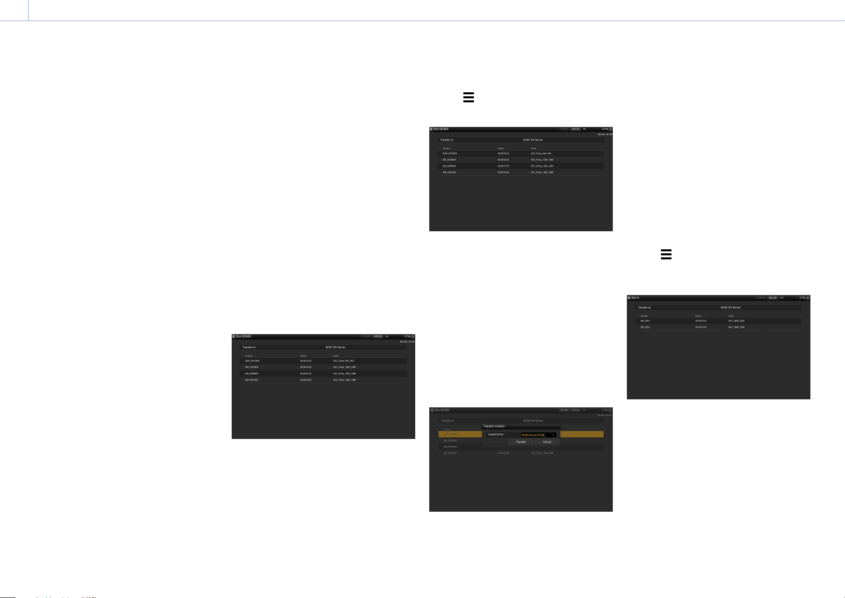
4. Network Functions: Using Web Remote Control
60
Display Password
Shows/hides the password.
When set to Off, the configured password is
not displayed. When entering a password, all
characters are displayed as asterisks.
When set to On, the configured password
is displayed. When entering a password, all
characters are displayed.
Passive Mode
Turn passive mode on/off.
Destination Directory
Enter the directory on the destination server.
[Note]
If characters that are invalid on the destination server
are entered in the destination directory, files will
be transferred to the user’s home directory. Invalid
characters will vary depending on the server.
Using Secure Protocol
Set whether to perform secure FTP uploading.
Setting to ON displays the certificate status.
To import or clear a certificate, tap Select
Function and select a task in the displayed
menu.
Load
Load a CA certificate.
* The certificate to be loaded must be in PEM
format, and should be written to the root
directory of the SD card with “certification.pem”
file name.
Clear
Clear the CA certificate.
None
Do not load or clear a certificate.
[Note]
Set the clock of the camcorder to the correct time before
importing a CA certificate.
Changing registered server settings
Select the server whose settings you want to
change on the Upload Settings screen, then
tap Edit. Change the settings as required on
the displayed screen.
You can also set a server using File Transfer
(page 105) in the Network menu.
Uploading a proxy file automatically
Auto Upload On/Off
When Auto Upload On/Off is set to On and
the camcorder is connected to the Internet,
the camcorder automatically uploads a proxy
file to the transfer destination that is set using
Default Upload Server after recording.
Default Upload Server
Select the default destination file transfer
server.
File transfer management (File Transfer)
You can transfer original files recorded on an
XQD memory card or proxy files recorded on
an SD card, manage file transfer, and configure
the file transfer destination.
Transferring files (Slot A, Slot B, Slot SD/MS)
You can display a list of clips recorded on
media inserted in slot A/slot B or a list of proxy
files recorded on media inserted in the UTILITY
SD/MS card slot.
You can select a displayed file to upload the
file to a server on the Internet.
Uploading a proxy file on an SD card
1 Connect the camcorder and device using
a LAN connection (page 49).
2 Launch a browser on the device and
display the web remote control
(page 58).
3 Display the file list screen to select a file.
Tap
>File Transfer >Slot SD/MS.
A file list screen for the media inserted in
the UTILITY SD/MS card slot appears.
4 Select the file to upload.
Tap the file to select it. To cancel, tap the
file again.
You can double-tap the file to play the file
and check the contents (SD card only).
5 Tap Transfer.
The server that you set using Default
Upload Server in “Registering a
destination server” (page 59) appears.
To change the server, tap the server to
display the server list, then select a server.
Input the name of the directory on the
server in Directory if necessary.
6 Tap Transfer.
The camcorder starts uploading the
selected file.
To cancel uploading, tap Cancel.
Uploading an original file on an XQD memory
card
[Tip]
The cover of the XQD card slot must be closed in order
to view information about the files on the XQD memory
card.
1 Connect the camcorder and device using
a LAN connection (page 49).
2 Launch a browser on the device and
display the web remote control
(page 58).
3 Display the file list screen to select a file.
Tap
>File Transfer >Slot A or Slot B.
A file list screen for the media inserted in
slot A or slot B appears.
Example: Slot A screen
4 Select the file to upload.
Tap the file to select it. To cancel, tap the
file again.
5 Tap Transfer.
The server that you set using Default
Upload Server in “Registering a
destination server” (page 59) appears.
To change the server, tap the server to
display the server list, then select a server.
Input the name of the directory on the
server in Directory if necessary.

4. Network Functions: Using Web Remote Control
61
6 Tap Transfer.
The camcorder starts uploading the
selected file.
To cancel uploading, tap Cancel.
Checking the file transfer (Job List)
You can check the list of the files to be
uploaded, the file that is being uploaded,
cancel or start the file upload, and delete the
file from the file list.
The camcorder is compatible with the FTP
resume function (resume upload for a file
whose transfer was suspended).
Total: Progress of all the files to be
uploaded.
Status: Progress of the file that is currently
being uploaded.
Remain Time: Estimated remaining time for
uploading.
Transfer data rate: Transfer rate indication.
To cancel or start uploading, or delete a file
from the file list
1 Select a file.
2 Tap at the upper right of the screen,
and select an item.
Abort selected: Cancel uploading the
selected file.
Delete from list: Delete the selected file
from the list.
Start selected: Start uploading the
selected file.
Clear completed: Delete the list of
uploaded files.
Select All: Select all files in the list.

62
5. Thumbnail Screen
Thumbnail Screen
The thumbnail screen appears if you press the THUMBNAIL button (page 7). The thumbnail screen displays the clips stored on XQD memory cards as thumbnails (index pictures).
You can select a clip on the thumbnail screen and start playback of that clip. The playback image can be displayed in the viewfinder and on an external monitor.
Pressing the THUMBNAIL button again closes the thumbnail screen and returns to the camera image.
[Note]
Only the clips recorded in the currently selected recording format are displayed on the thumbnail screen. If an expected recorded clip is not displayed, check the recording format. Take special note of this fact before formatting (initializing)
media.
Screen Layout
Information for the clip at the cursor position is displayed at the bottom of the screen.
4 5
6
3
1
2
Currently selected XQD memory card indicator
(A lock icon is displayed if the card is protected.)
Cursor (yellow)
Clip number/Total number of clips
1. Thumbnail (index picture)
Displays the index picture of a clip. When a
clip is recorded, its first frame is automatically
set as the index picture.
Clip/frame information is displayed below
the thumbnail. You change the information
displayed using Customize View (page 98)
>Thumbnail Caption in the Thumbnail menu.
2. Clip name
Displays the name of the selected clip.
3. Recording video format
Displays the file format of the selected clip.
4. Special recording information
Displays the recording mode only if the clip
was recorded using a special recording mode.
For Slow & Quick Motion clips, the frame rate
is displayed on the right.
5. Clip duration
6. Creation date

5. Thumbnail Screen
63
Playing Clips
Playing Recorded Clips
You can play recorded clips when the
camcorder is in recording standby (Stby)
mode.
1 Insert an XQD memory card for playback.
2 Press the THUMBNAIL button.
3 Use the arrow buttons (page 7) or
multi-function dial (page 4) to move
the cursor to the thumbnail for the clip
you want to play.
4 Press the SET button or multi-function
dial.
Playback begins from the start of the
selected clip.
You can control playback by pressing the
following buttons.
Press the SET button or multi-function dial:
Pauses playback.
Press again to return to normal playback.
Press the left/right arrow buttons:
Jumps to start of clip/start of next clip.
Press and hold the left/right arrow buttons:
Fast reverse/forward.
Returns to normal playback when you
release the button.
CANCEL/BACK button:
Stops playback, and returns to recording
standby mode.
[Notes]
There may be momentary picture breakup or still
image display at the boundary between clips. You
cannot operate the camcorder during this period.
When you select a clip in the thumbnail screen and
begin playback, there may be momentary picture
breakup at the start of the clip. To start playback
without distortion from the beginning of the clip,
pause playback once after starting it, press the left
arrow button to return to the start of the clip, then
restart playback.
You can also use the multi selector (page 9).

5. Thumbnail Screen
64
On the thumbnail screen, you can operate
the clips or check clip properties using the
Thumbnail menu.
The Thumbnail menu (page 97) appears
when you press the MENU button and select a
thumbnail.
Thumbnail Menu Operations
Use the arrow buttons (page 7) or the
multi-function dial (page 4) to select a
function, then press the SET button or multi-
function dial.
Press the CANCEL/BACK button (page 7)
to return to the previous screen.
[Tip]
You can also use the multi selector (page 9).
[Note]
Some items cannot be selected, depending on the state
when the menu was displayed.
Menu Items for Clip Operations
Display Clip Properties
Set Shot Mark
Set Clip Flag
Lock/Unlock Clip
Delete Clip
Copy Clip
Copy Sub Clip
Transfer Clip
Transfer Clip (Proxy)
Set Index Picture
Thumbnail View
Filter Clips
Customize View
For details about clip operation menu items,
see the Thumbnail menu (page 97).
Displaying clip properties
Select Display Clip Properties (page 97)
in the Thumbnail menu to display the clip
properties screen.
Displaying the essence mark thumbnail
screen
Select Thumbnail View (page 98) >Essence
Mark Thumbnail in the Thumbnail menu, and
select the essence mark type to display a
thumbnail view of the frames that have the
specified essence mark.
To display all clips, set Thumbnail View
>Essence Mark Thumbnail in the Thumbnail
menu to All.
Displaying the filtered clip thumbnail
screen
Select Filter Clips (page 98) in the
Thumbnail menu, and select a clip flag type to
display only those clips that have the specified
flag.
To display all clips, select All.
[Tip]
You can also switch filters in sequence using the
DISPLAY button.
Deleting clips
You can delete clips from XQD memory cards.
Select Delete Clip >Select Clip or All Clips in
the Thumbnail menu.
Select Clip:
Deletes the selected clip. Multiple clip
selection is supported.
All Clips:
Deletes all of the displayed clips.
Changing the information displayed on
the thumbnail screen
You can change the clip/frame information
displayed below the thumbnail.
Select Customize View >Thumbnail Caption
in the Thumbnail menu and select the
information to display.
Date Time:
Displays the date and time the clip was
created and last modified.
Time Code:
Displays the timecode.
Duration::
Displays the duration of the clip.
Sequential Number:
Displays a sequential number on each
thumbnail.
Clip Operations

65
6. Menu Display and Settings
Setup Menu Configuration and Hierarchy
Press the MENU button to display the setup
menu in the viewfinder to specify various
items for shooting, recording, and playback
(menu can also be displayed on an external
monitor). The setup menu comprises the
following menus.
Menu Configuration
User menu
Contains menu items configured by the
user using Edit User Menu.
Edit User menu
Contains menu items for editing the User
menu.
Shooting menu
Contains settings related to shooting.
Project menu
Contains basic project settings.
Paint menu
Contains settings related to image quality.
TC/Media menu
Contains settings related to timecodes
and recording media.
Monitoring menu
Contains settings related to video output
and the viewfinder display.
Audio menu
Contains settings related to audio.
Thumbnail menu
Contains settings related to thumbnail
display.
Technical menu
Contains settings for technical items.
Network menu
Contains settings related to networks.
Maintenance menu
Contains devices settings, such as the
clock and language.
Setup Menu Hierarchy
User
(Factory settings)
Base Setting
Rec Format
ISO/Gain/EI
Focus
S&Q Motion
Monitor LUT
Monitor LUT Setting
Simul Rec
4K & HD (Sub) Rec
Proxy Rec
Picture Cache Rec
Assignable Button
Assignable Dial
Multi Function Dial
All File
Clip Name Format
Format Media
Output Format
VF Setting
Menu Settings
Edit User Menu Add Item
Customize Reset
Shooting ISO/Gain/EI
ND Filter
Shutter
Auto Exposure
White
White Setting
Offset White
Focus
S&Q Motion
Monitor LUT
Monitor LUT Setting
Noise Suppression
Flicker Reduce
SteadyShot
Auto Black Balance
Project Base Setting
Rec Format
Cine EI Setting
Simul Rec
4K & HD (Sub) Rec
Proxy Rec
Interval Rec
Picture Cache Rec
SDI/HDMI Rec Control
Assignable Button
Assignable Dial
Multi Function Dial
User File
All File
Planning Metadata
Paint Black
Gamma
Black Gamma
Knee
White Clip
Detail(QFHD)
Detail(HD)
Skin Detail
Aperture
Matrix
Multi Matrix
Scene File
TC/Media Timecode
TC Display
Users Bit
HDMI TC Out
Clip Name Format
Update Media
Format Media
Monitoring Output On/Off
Output Format
Output Display
Display On/Off
Marker
VF Setting
Gamma Display Assist
Peaking
Zebra
Audio Audio Input
Audio Output

6. Menu Display and Settings: Setup Menu Configuration and Hierarchy
66
Thumbnail Display Clip Properties
Set Shot Mark
Set Clip Flag
Lock/Unlock Clip
Delete Clip
Copy Clip
Copy Sub Clip
Transfer Clip
Transfer Clip (Proxy)
Set Index Picture
Thumbnail View
Filter Clips
Customize View
Technical Color Bars
Test Saw
ND Dial
Tally
HOLD Switch Setting
Rec Review
Handle Zoom
GPS
Menu Settings
Fan Control
Lens
Video Light Set
APR
Camera Battery Alarm
Camera DC IN Alarm
Ext. Unit Battery Alarm
Ext. Unit DC IN Alarm
Network Access Authentication
Wireless LAN
AP Mode Settings
ST Mode Settings
Wired LAN
Modem
Network Client Mode
File Transfer
Network Reset
Maintenance Language
Clock Set
All Reset
Hours Meter
Version

6. Menu Display and Settings
67
Setup Menu Operations
Press the MENU button to display the setup
menu in the viewfinder to specify various
items for shooting, recording, and playback
(menu can also be displayed on an external
monitor).
Menu Controls
MENU button (page 7)
Turns menu mode for setup menu
operations on/off.
////SET button (page 7)
Press the arrows buttons to move the
cursor up/down/left/right to select menu
items or settings.
Press the SET button to apply the selected
item.
[Tip]
You can also use the multi selector (page 9) in
the same way.
Multi-function dial (page 4)
Turn the multi-function dial to move the
cursor up/down to select menu items or
settings.
Press the multi-function dial to apply the
selected item.
CANCEL/BACK button (page 7)
Press to return to the previous menu. An
uncompleted change is canceled.
[Notes]
The setup menu cannot be operated when in focus
magnifier mode (page 34).
Some items cannot be selected, depending on the
state when the menu was displayed.
Setting Menu Items
Press the arrow buttons or turn the multi-
function dial to move the cursor to the menu
item to set, then press the SET button or multi-
function dial to select the item.
The menu item selection area displays up
to eight lines. If the available options for an
item cannot be displayed at the same time,
scroll the display by moving the cursor up/
down.
For sub-items with a large settings range
(for example, –99 to +99), the settings area
is not displayed. The current setting is
highlighted to indicate that the value can be
changed.
Selecting [Execute] for a function will
execute the corresponding function.
Selecting an item that requires confirmation
before execution will temporarily hide the
menu and display a confirmation message.
Check the message, and then select
whether to execute or cancel the function.
Entering a Character String
When you select an item, such as a file name,
which requires character entry, the character
entry screen appears.
1
2 3
1 Press the arrow buttons or turn the multi-
function dial to select a character type,
then apply the setting.
ABC: Uppercase alphabetic characters
abc: Lowercase alphabetic characters
123: Numeric characters
!#$: Special characters
2 Select a character from the selected
character type, then apply the setting.
The cursor moves to the next field.
Space: Enters a space character at the
cursor position.
/: Moves the position of the cursor.
BS: Deletes the character on the left of the
cursor (backspace).
3 When finished, select [Done] and apply
the setting.
The character string is confirmed and the
character entry screen disappears.
Locking and Unlocking the Menu
You can lock the setup menu so that only the
User menu is displayed.
Locking the menu
1 Press and hold the multi-function dial and
press the MENU button.
2 Select Menu Settings >User Menu with
Lock in the Technical menu.
[Note]
When only the MENU button is pressed to display
the normal setup menu, User Menu Only is
displayed under Menu Settings in the Technical
menu. Press and hold the multi-function dial and
press the MENU button to display User Menu with
Lock.
3 Set to On, and press the SET button or
multi-function dial.
The viewfinder screen display switches to
the passcode number input screen.
4 Enter an arbitrary number.
Enter a 4-digit number in the range 0000
to 9999. The default value is 0000.
Enter a number and press the SET button
or multi-function dial to move the cursor
to the next digit.
When all digits have been entered, move
the cursor to SET.
5 Press the SET button or multi-function
dial.
The entry is applied.
A confirmation message appears, and the
screen switches to the User menu display.
6. Menu Display and Settings: Setup Menu Operations
68
Unlocking the menu
1 Press and hold the multi-function dial and
press the MENU button.
2 Select Menu Settings >User Menu with
Lock in the User menu.
[Note]
When only the MENU button is pressed to display
the normal setup menu, User Menu Only is
displayed under Menu Settings in the Technical
menu. Press and hold the multi-function dial and
press the MENU button to display User Menu with
Lock.
3 Set to Off, and press the SET button or
multi-function dial.
The viewfinder screen display switches to
the passcode number input screen.
4 Enter the passcode number used to lock
the menu.
Enter a number and press the SET button
or multi-function dial to move the cursor
to the next digit.
When all digits have been entered, move
the cursor to Set.
5 Press the SET button or multi-function
dial.
The entry is applied.
If the entered passcode number matches
the passcode number used to lock the
menu, the menu is unlocked and the
menu is displayed.
[Note]
If the entered passcode number does not match the
passcode number used to lock the menu, the menu is
not unlocked.
It is recommended that you leave a record of the
passcode nearby, just in case it is forgotten. If you
do forget the passcode number, contact your Sony
service representative.
If the menu is locked without registering setup menu
items from the following tables in the User menu,
those functions cannot be assigned to assignable
buttons.
If those functions were already assigned to assignable
buttons, the assignable setting is forcibly disabled at
the point when the menu is locked.
Setup menu item Assignable button
selection
Shooting >ISO/Gain/EI
>Base Sensitivity,
Shooting >ISO/Gain/EI>
Base ISO
Base ISO/Sensitivity
Shooting >Auto
Exposure >AGC
AGC
Shooting >Auto
Exposure >Auto ND
Filter
Auto ND Filter
Shooting >Auto
Exposure >Auto Shutter
Auto Shutter
Shooting >Auto
Exposure >Level
Auto Exposure Level
Shooting >Auto
Exposure >Mode
Backlight
Shooting >Auto
Exposure >Mode
Spotlight
Shooting >White
>Preset White
Preset White Select
Shooting >Focus
>Focus Area
Focus Area
Shooting >Focus
>Focus Area(AF-S)
Focus Area(AF-S)
Shooting >Focus >Face
Detection AF
Face Detection AF
Shooting >Focus >Push
AF Mode
Push AF Mode
Shooting >S&Q Motion
>Setting
S&Q Motion
Shooting >SteadyShot
>Setting
SteadyShot
Project >Picture Cache
Rec >Setting
Picture Cache Rec
Setup menu item Assignable button
selection
Technical >Rec Review
>Setting
Rec Review
Thumbnail >Set Shot
Mark >Add Shot Mark1
Shot Mark1
Thumbnail >Set Shot
Mark >Add Shot Mark2
Shot Mark2
Thumbnail >Set Clip
Flag >Add OK
Clip Flag OK
Thumbnail >Set Clip
Flag >Add NG
Clip Flag NG
Thumbnail >Set Clip
Flag >Add KEEP
Clip Flag Keep
Technical >Color Bars
>Setting
Color Bars
Monitoring >Display
On/Off >Lens Info
Lens Info
Monitoring >Display
On/Off >Video Signal
Monitor
Video Signal
Monitor
Monitoring >Marker
>Setting
Marker
Monitoring >VF Setting
>Color Mode
VF Mode
Monitoring >Gamma
Display Assist >Setting
Gamma Display
Assist
Monitoring >Peaking
>Setting
Peaking
Monitoring >Zebra
>Setting
Zebra
Technical >Handle
Zoom >Setting
Handle Zoom
Network >Wireless LAN
>NFC
NFC
Network >Network
Client Mode >Setting
Network Client
Mode
Network >File Transfer
>Auto Upload (Proxy)
Auto Upload (Proxy)
User User Menu
6. Menu Display and Settings
69
User Menu
This section describes the function and settings of each menu item.
User
Item Description
Base Setting Project >Base Setting item
Rec Format Project >Rec Format item
ISO/Gain/EI Shooting >ISO/Gain/EI item
Focus Shooting >Focus item
S&Q Motion Shooting >S&Q Motion item
Monitor LUT Shooting >Monitor LUT item
Monitor LUT Setting Shooting >Monitor LUT Setting item
Simul Rec Project >Simul Rec item
4K & HD (Sub) Rec Project >4K & HD (Sub) Rec item
Proxy Rec Project >Proxy Rec item
Picture Cache Rec Project >Picture Cache Rec item
Assignable Button Project >Assignable Button item
Assignable Dial Project >Assignable Dial item
Multi Function Dial Project >Multi Function Dial item
All File Project >All File item
Clip Name Format TC/Media >Clip Name Format item
Format Media TC/Media >Format Media item
Output Format Monitoring >Output Format item
VF Setting Monitoring >VF Setting item
Menu Settings Technical >Menu Settings item
Edit User Menu Displays the Edit User menu screen.
[Note]
You can add and remove menu items in the User menu using the Edit User menu. Up to 20 items can be configured.
The camcorder is configured with 20 items by default. To add an item, you first have to delete an existing item using
Delete in the Edit User menu and then add an item using Add Item.
6. Menu Display and Settings
70
Edit User Menu
The Edit User menu is displayed at the top level when Edit User Menu is selected in the User
menu.
Edit User
Item Sub-item setting Description
Add Item
Add an item to the User
menu
Adds a menu item to the User menu.
Customize Reset
Reset the items in the
User menu
Restores the menu items registered
in the User menu to the factory
default.
Menu item selected
during editing
Delete Deletes the registered menu item
from the User menu.
Move Rearranges the registered menu
items within the User menu.
Edit Sub Item Edits (register/delete) the registered
menu sub-item in the User menu.

6. Menu Display and Settings
71
Shooting Menu
This section describes the function and settings of each menu item.
Factory default settings are shown in bold (for example, 18dB).
Shooting >ISO/Gain/EI
Sets gain settings.
Item Sub-item setting Description
Mode ISO/dB Selects the gain setting mode.
Shooting >ISO/Gain/EI
Sets gain settings.
Item Sub-item setting Description
ISO/Gain<H> When Mode is set to ISO with dynamic
range of 460% and Base Sensitivity is set
to High:
ISO 1600 / ISO 2000 / ISO 2500 /
ISO 3200 / ISO 4000 / ISO 5000 /
ISO 6400 / ISO 8000 / ISO 10000 /
ISO 12800
When Mode is set to ISO with dynamic
range of 460% and Base Sensitivity is set
to Low:
ISO 320 / ISO 400 / ISO 500 / ISO 640 /
ISO 800 / ISO 1000 / ISO 1250 /
ISO 1600 / ISO 2000 / ISO 2500
When Mode is set to ISO with dynamic
range of 800% and Base Sensitivity is set
to High:
ISO 2500 / ISO 3200 / ISO 4000 /
ISO 5000 / ISO 6400 / ISO 8000 /
ISO 10000 / ISO 12800 / ISO 16000 /
ISO 20000
When Mode is set to ISO with dynamic
range of 800% and Base Sensitivity is set
to Low:
ISO 500 / ISO 640 / ISO 800 / ISO 1000 /
ISO 1250 / ISO 1600 / ISO 2000 /
ISO 2500 / ISO 3200 / ISO 4000
When Mode is set to ISO with dynamic
range of 1300% and Base Sensitivity is set
to High:
ISO 4000 / ISO 5000 / ISO 6400 /
ISO 8000 / ISO 10000 / ISO 12800 /
ISO 16000 / ISO 20000 / ISO 25600 /
ISO 32000
When Mode is set to ISO with dynamic
range of 1300% and Base Sensitivity is set
to Low:
ISO 800 / ISO 1000 / ISO 1250 /
ISO 1600 / ISO 2000 / ISO 2500 /
ISO 3200 / ISO 4000 / ISO 5000 /
ISO 6400
When Mode is set to dB:
–3dB to 18dB (12dB) (1dB increments)
Sets the <H> gain preset value.
[Tip]
The dynamic range is determined by the
gamma.
Gamma Dynamic
range
STD / HG1 / HG2 /
HG3 / HG4 /
S-Cinetone
460%
HG7 / HG8 / User 800%
S-Log3 1300%

6. Menu Display and Settings: Shooting Menu
72
Shooting >ISO/Gain/EI
Sets gain settings.
Item Sub-item setting Description
ISO/Gain<M> (Same settings as ISO/Gain<H>)
The default values are given below.
When Mode is set to ISO with dynamic
range of 460% and Base Sensitivity is set
to High:
ISO 3200
When Mode is set to ISO with dynamic
range of 460% and Base Sensitivity is set
to Low:
ISO 640
When Mode is set to ISO with dynamic
range of 800% and Base Sensitivity is set
to High:
ISO 5000
When Mode is set to ISO with dynamic
range of 800% and Base Sensitivity is set
to Low:
ISO 1000
When Mode is set to ISO with dynamic
range of 1300% and Base Sensitivity is set
to High:
ISO 8000
When Mode is set to ISO with dynamic
range of 1300% and Base Sensitivity is set
to Low:
ISO 1600
When Mode is set to dB:
6dB
Sets the <M> gain preset value.
Shooting >ISO/Gain/EI
Sets gain settings.
Item Sub-item setting Description
ISO/Gain<L> (Same settings as ISO/Gain<H>)
The default values are given below.
When Mode is set to ISO with dynamic
range of 460% and Base Sensitivity is set
to High:
ISO 1600
When Mode is set to ISO with dynamic
range of 460% and Base Sensitivity is set
to Low:
ISO 320
When Mode is set to ISO with dynamic
range of 800% and Base Sensitivity is set
to High:
ISO 2500
When Mode is set to ISO with dynamic
range of 800% and Base Sensitivity is set
to Low:
ISO 500
When Mode is set to ISO with dynamic
range of 1300% and Base Sensitivity is set
to High:
ISO 4000
When Mode is set to ISO with dynamic
range of 1300% and Base Sensitivity is set
to Low:
ISO 800
When Mode is set to dB:
0dB
Sets the <L> gain preset value.
6. Menu Display and Settings: Shooting Menu
73
Shooting >ISO/Gain/EI
Sets gain settings.
Item Sub-item setting Description
Exposure
Index<H>
When Base ISO is set to ISO 800:
200EI / 4.0E
250EI / 4.3E
320EI / 4.7E
400EI / 5.0E
500EI / 5.3E
640EI / 5.7E
800EI / 6.0E
1000EI / 6.3E
1250EI / 6.7E
1600EI / 7.0E
2000EI / 7.3E
2500EI / 7.7E
3200EI / 8.0E
When Base ISO is set to ISO 4000:
1000EI / 4.0E
1250EI / 4.3E
1600EI / 4.7E
2000EI / 5.0E
2500EI / 5.3E
3200EI / 5.7E
4000EI / 6.0E
5000EI / 6.3E
6400EI / 6.7E
8000EI / 7.0E
10000EI / 7.3E
12800EI / 7.7E
16000EI / 8.0E
Sets the <H> exposure index value.
Available in Cine EI mode only.
Exposure
Index<M>
(Same settings as Exposure Index<H>)
When Base ISO is set to ISO 800:
1000EI / 6.3E
When Base ISO is set to ISO 4000:
5000EI / 6.3E
Sets the <M> exposure index value.
Exposure
Index<L>
(Same settings as Exposure Index<H>)
When Base ISO is set to ISO 800:
800EI / 6.0E
When Base ISO is set to ISO 4000:
4000EI / 6.0E
Sets the <L> exposure index value.
Shockless
Gain
On / Off Turns the shockless gain function on/off.
Shooting >ISO/Gain/EI
Sets gain settings.
Item Sub-item setting Description
Base
Sensitivity
High / Low Sets the base sensitivity for SDR/HDR
mode.
Base ISO
ISO 4000 / ISO 800 Sets the base ISO sensitivity for Cine EI
mode.
Shooting >ND Filter
Sets the preset values for the ND filter.
Item Sub-item setting Description
Preset1 1/4 / 1/8 / 1/16 / 1/32 / 1/64 / 1/128 Sets the preset 1 value for the ND filter.
Preset2
1/4 / 1/8 / 1/16 / 1/32 / 1/64 / 1/128 Sets the preset 2 value for the ND filter.
Preset3
1/4 / 1/8 / 1/16 / 1/32 / 1/64 / 1/128 Sets the preset 3 value for the ND filter.
Shooting >Shutter
Sets electronic shutter operating condition settings.
Item Sub-item setting Description
Mode Speed / Angle Selects the operating mode of the
electronic shutter.
Used for shooting fast-moving subjects
clearly. Selects the mode for setting the
shutter speed in seconds (Speed) or as a
shutter angle (Angle).
Shutter
Speed On/
Off
On / Off Sets whether the exposure time when
Speed mode is selected follows the
Shutter Speed value or is set for full
exposure.
6. Menu Display and Settings: Shooting Menu
74
Shooting >Shutter
Sets electronic shutter operating condition settings.
Item Sub-item setting Description
Shutter
Speed
64F to 1/8000
The available settings vary depending on
the frame frequency of the selected video
format.
59.94P / 59.94i:
64F / 32F / 16F / 8F / 7F / 6F / 5F / 4F /
3F / 2F / 1/50 / 1/60 / 1/100 / 1/120 /
1/125 / 1/250 / 1/500 / 1/1000 /
1/2000 / 1/4000 / 1/8000
50P / 50i:
64F / 32F / 16F / 8F / 7F / 6F / 5F / 4F /
3F / 2F / 1/50 / 1/60 / 1/100 / 1/120 /
1/125 / 1/250 / 1/500 / 1/1000 /
1/2000 / 1/4000 / 1/8000
29.97P:
64F / 32F / 16F / 8F / 7F / 6F / 5F / 4F /
3F / 2F / 1/30 / 1/40 / 1/50 / 1/60 /
1/100 / 1/120 / 1/125 / 1/250 / 1/500 /
1/1000 / 1/2000 / 1/4000 / 1/8000
25P:
64F / 32F / 16F / 8F / 7F / 6F / 5F / 4F /
3F / 2F / 1/25 / 1/33 / 1/50 / 1/60 /
1/100 / 1/120 / 1/125 / 1/250 / 1/500 /
1/1000 / 1/2000 / 1/4000 / 1/8000
23.98P:
64F / 32F / 16F / 8F / 7F / 6F / 5F / 4F /
3F / 2F / 1/24 / 1/32 / 1/48 / 1/50 /
1/60 / 1/96 / 1/100 / 1/120 / 1/125 /
1/250 / 1/500 / 1/1000 / 1/2000 /
1/4000 / 1/8000
Sets the shutter speed when Mode is set
to Speed.
Shutter Angle
64F / 32F / 16F / 8F / 7F / 6F / 5F / 4F /
3F / 2F / 360.0° / 300.0° / 270.0° / 240.0° /
216.0° / 210.0° / 180.0° / 172.8° / 150.0° /
144.0° / 120.0° / 90.0° / 86.4° / 72.0° /
45.0° / 30.0° / 22.5° / 11.25° / 5.6°
Sets the shutter angle when Mode is set
to Angle.
ECS On/Off
On / Off Turns the Extended Clear Scan frequency
setting on/off.
Shooting >Shutter
Sets electronic shutter operating condition settings.
Item Sub-item setting Description
ECS
Frequency
23.99 to 8000
The available settings vary depending on
the frame frequency of the selected video
format.
The default values are given below.
59.94P: 60.00
59.94i: 60.00
50P: 50.00
50i: 50.00
29.97P: 30.00
23.98P: 23.99
25P: 25.02
Sets the ECS frequency when Mode is set
to ECS.
Shooting >Auto Exposure
Sets automatic exposure adjustment settings.
Item Sub-item setting Description
Level +3.0 / +2.75 / +2.5 / +2.25 / +2.0 / +1.75 /
+1.5 / +1.25 / +1.0 / +0.75 / +0.5 / +0.25 /
±0 / –0.25 / –0.5 / –0.75 / –1.0 / –1.25 /
–1.5 / –1.75 / –2.0 / –2.25 / –2.5 / –2.75 /
–3.0
Sets the brightness level for the
automatically detected exposure.
Mode
Backlight / Standard / Spotlight Sets the operating mode of auto
exposure adjustment.
Backlight:
Backlight mode (mode for reduced
darkening of a subject when the
subject is backlit)
Standard:
Standard mode
Spotlight:
Spotlight mode (mode for reduced
clipped whites when subject is lit by
spotlighting)
Speed
–99 to +99 (±0) Sets the adjustment speed of auto
exposure adjustment.
AGC
On / Off Turns the AGC (auto gain control)
function on/off.
6. Menu Display and Settings: Shooting Menu
75
Shooting >Auto Exposure
Sets automatic exposure adjustment settings.
Item Sub-item setting Description
AGC Limit When ISO/Gain/EI Mode is set to dB:
3dB / 6dB / 9dB / 12dB / 15dB / 18dB
When ISO/Gain/EI >Mode is set to ISO with
dynamic range of 460% and Base
Sensitivity is set to High:
ISO 2000 / ISO 2500 / ISO 3200 /
ISO 4000 / ISO 5000 / ISO 6400 /
ISO 8000 / ISO 10000 / ISO 12800
When ISO/Gain/EI >Mode is set to ISO with
dynamic range of 460% and Base
Sensitivity is set to Low:
ISO 400 / ISO 500 / ISO 640 /
ISO 800 / ISO 1000 / ISO 1250 /
ISO 1600 / ISO 2000 / ISO 2500
When ISO/Gain/EI >Mode is set to ISO with
dynamic range of 800% and Base
Sensitivity is set to High:
ISO 3200 / ISO 4000 / ISO 5000 /
ISO 6400 / ISO 8000 / ISO 10000 /
ISO 12800 / ISO 16000 / ISO 20000
When ISO/Gain/EI >Mode is set to ISO with
dynamic range of 800% and Base
Sensitivity is set to Low:
ISO 640 / ISO 800 / ISO 1000 /
ISO 1250 / ISO 1600 / ISO 2000 /
ISO 2500 / ISO 3200 / ISO 4000
When ISO/Gain/EI >Mode is set to ISO with
dynamic range of 1300% and Base
Sensitivity is set to High:
ISO 5000 / ISO 6400 / ISO 8000 /
ISO 10000 / ISO 12800 / ISO 16000 /
ISO 20000 / ISO 25600 / ISO 32000
When ISO/Gain/EI >Mode is set to ISO with
dynamic range of 1300% and Base
Sensitivity is set to Low:
ISO 1000 / ISO 1250 / ISO 1600 /
ISO 2000 / ISO 2500 / ISO 3200 /
ISO 4000 / ISO 5000 / ISO 6400
Sets the maximum gain of the AGC
function.
AGC Point
F2.8 / F4 / F5.6 Sets the F-stop value of the iris where
AGC operation starts when the AGC
function is On.
Shooting >Auto Exposure
Sets automatic exposure adjustment settings.
Item Sub-item setting Description
Auto Shutter On / Off Turns the auto shutter control function
on/off.
A.SHT Limit
1/100 / 1/150 / 1/200 / 1/250 / 1/2000 Sets the fastest shutter speed of the auto
shutter function.
A.SHT Point
F5.6 / F8 / F11 / F16 Sets the F-stop value of the iris where
auto shutter operation starts.
Clip High
light
On / Off Turns the function that ignores brightest
areas to provide a flatter reaction to high
luminance on/off.
Detect
Window
1 / 2 / 3 / 4 / 5 / 6 / Custom Sets the light metering range for
automatically adjusting the exposure
according to the brightness of the
subject. (Not available when adjusting
exposure manually)
Detect
Window
Indication
On / Off Turns the light metering range indication
on/off.
Average Peak
Level Ratio
–99 to +99 (±0) Sets the ratio between the average value
and the peak of the video signal used for
Auto Exposure detection.
Custom
Width
40 to 999 (500) Sets the width of the light metering
range.
Custom
Height
70 to 999 (500) Sets the height of the light metering
range.
Custom H
Position
–479 to +479 (±0) Sets the horizontal position of the light
metering range.
Custom V
Position
–464 to +464 (±0) Sets the vertical position of the light
metering range.

6. Menu Display and Settings: Shooting Menu
76
Shooting >White
Sets white balance settings.
Item Sub-item setting Description
Preset White 2000K to 15000K (3200K) Sets the white balance preset value.
Color Temp
<A>
2000K to 15000K (3200K) Sets the white balance color temperature
saved in memory A.
[Note]
Since Color Temp is clipped at 2000K and
15000K during R/B Gain operation, it may not
be possible to display the correct Color Temp
value for the R/B Gain value.
Tint<A> –99 to +99 (±0) Sets the white balance tint value saved in
white memory A.
[Note]
Since Tint is clipped at ±99 during R/B Gain
operation, it may not be possible to display the
correct Tint value for the R/B Gain value.
R Gain <A> –99.0 to +99.0 (±0.0) Sets the white balance R gain value
saved in memory A.
B Gain <A>
–99.0 to +99.0 (±0.0) Sets the white balance B gain value
saved in memory A.
Color Temp
<B>
2000K to 15000K (3200K) Sets the white balance color temperature
saved in memory B.
[Note]
Since Color Temp is clipped at 2000K and
15000K during R/B Gain operation, it may not
be possible to display the correct Color Temp
value for the R/B Gain value.
Tint<B> –99 to +99 (±0) Sets the white balance tint value saved in
white memory B.
[Note]
Since Tint is clipped at ±99 during R/B Gain
operation, it may not be possible to display the
correct Tint value for the R/B Gain value.
R Gain <B> –99.0 to +99.0 (±0.0) Sets the white balance R gain value
saved in memory B.
B Gain <B>
–99.0 to +99.0 (±0.0) Sets the white balance B gain value
saved in memory B.
Shooting >White Setting
Adjusts white balance settings.
Item Sub-item setting Description
Shockless
White
Off / 1 / 2 / 3 Sets the white balance response speed
when switching white balance mode.
Off: Switches instantaneously.
1 to 3: Switches more slowly the higher
the number.
ATW Speed
1 / 2 / 3 / 4 / 5 Sets the response speed in ATW mode.
1: Fastest response speed
White
Switch<B>
Memory / ATW Selects the white balance adjustment
mode that is selected when the WHT BAL
switch is set to B.
Filter White
Memory
On / Off Turns the function that sets the white
balance memory area for each ND filter
on/off.
On: Sets the white balance memory for
each ND filter.
[Tip]
In preset mode, there are four settings
(CLEAR / 1 / 2 / 3). In variable mode, there
are two settings (CLEAR / On).
Off: Sets white balance memory common
to all ND filters.
Shooting >Offset White
Sets white balance offset settings.
Item Sub-item setting Description
Offset White
<A>
On / Off Selects whether to add (On) or not to add
(Off) an offset value to the white balance
in memory A.
Offset Color
Temp<A>
–99 to +99 (±0) Sets the color temperature offset to be
added to the white balance in memory A
when Offset White <A> is set to On.
[Note]
Since Offset Color Temp is clipped at ±99
during R/B Gain operation, it may not be
possible to display the correct Offset Color
Temp value for the R/B Gain value.

6. Menu Display and Settings: Shooting Menu
77
Shooting >Offset White
Sets white balance offset settings.
Item Sub-item setting Description
Offset
Tint<A>
–99 to +99 (±0) Sets the Tint value offset to be added to
the white balance in memory A when
Offset White <A> is set to On.
[Note]
Since Offset Tint is clipped at ±99 during R/B
Gain operation, it may not be possible to
display the correct Offset Tint value for the R/B
Gain value.
Offset White
<B>
On / Off Selects whether to add (On) or not to add
(Off) an offset value to the white balance
in memory B.
Offset Color
Temp<B>
–99 to +99 (±0) Sets the color temperature offset to be
added to the white balance in memory B
when Offset White <B> is set to On.
[Note]
Since Offset Color Temp is clipped at ±99
during R/B Gain operation, it may not be
possible to display the correct Offset Color
Temp value for the R/B Gain value.
Offset
Tint<B>
–99 to +99 (±0) Sets the Tint value offset to be added to
the white balance in memory B when
Offset White <B> is set to On.
[Note]
Since Offset Tint is clipped at ±99 during R/B
Gain operation, it may not be possible to
display the correct Offset Tint value for the R/B
Gain value.
Offset White
<ATW>
On / Off Selects whether to add (On) or not to add
(Off) an offset value to the ATW white
balance.
Offset Color
Temp<ATW>
–99 to +99 (±0) Sets the color temperature offset to be
added to the ATW white balance when
Offset White <ATW> is set to On.
Offset
Tint<ATW>
–99 to +99 (±0) Sets the Tint value offset to be added to
the ATW white balance when Offset
White <ATW> is set to On.
Shooting >Focus
Sets focus settings.
Item Sub-item setting Description
AF Transition
Speed
1(Slow) / 2 / 3 / 4 / 5 / 6 / 7(Fast) Sets the speed of the focus drive for
when the subject changes during auto
focus.
AF Subj. Shift
Sens.
1(Locked On) / 2 / 3 / 4 / 5(Responsive) Sets the sensitivity for changing subject
focus during auto focus.
Focus Area
Wide / Zone / Flexible Spot Sets the target area for auto focus and
push auto focus (AF) (page 31).
Wide:
Searches for a subject over a wide
angle of the image when focusing.
Zone:
Automatically searches for a focus
point within the specified zone.
Flexible Spot:
Focuses on a specified position in the
image.
Focus Area
(AF-S)
Flexible Spot
Sets the target area for push auto focus
(AF-S).
Face
Detection AF
Face Only AF / Face Priority AF / Off Enables/disables face detection AF.
Push AF
Mode
AF / Single-shot AF(AF-S) Sets the push auto focus mode.
AF Assist
On / Off When set to On, allows you to
temporarily override auto focus and set
focus manually.
Shooting >S&Q Motion
Sets Slow & Quick Motion mode settings (page 42).
Item Sub-item setting Description
Setting On / Off Turns Slow & Quick Motion on/off.
When set to On, the following functions
are disabled.
Auto iris
Auto focus
Frame Rate 1fps to 60fps / 100fps / 120fps Sets the frame rate for Slow & Quick
Motion shooting.
[Note]
The available settings vary depending on the
selected system frequency, codec, and video
format.

6. Menu Display and Settings: Shooting Menu
78
Shooting >Monitor LUT
Sets monitor LUT settings. Available only when shooting in Cine EI mode.
Item Sub-item setting Description
LUT Select 709(800%) / HG8009G40 / HG8009G33 /
S-Log3 / s709
Selects the monitor LUT type.
709(800%):
Signal with ITU-R709 base curve with
extended dynamic range up to 800%.
HG8009G40:
Signal using HyperGamma with 800%
dynamic range, 109% white limit, and
18% gray card video output of 40%.
HG8009G33:
Signal using HyperGamma with 800%
dynamic range, 109% white limit, and
18% gray card video output of 33%.
S-Log3:
Log signal with 1300% dynamic range
that mimics film characteristics, close
to Cineon Log curve.
s709:
Cinema color equivalent to
709(800%).
Shooting >Monitor LUT Setting
Adjusts monitor LUT settings. Available only when shooting in Cine EI mode.
Item Sub-item setting Description
Internal Rec MLUT On / MLUT Off Selects whether to apply monitor LUT to
the main video recorded on XQD memory
cards.
Monitor Out
MLUT On / MLUT Off Selects whether to apply monitor LUT to
recorded video and video output, other
than the main video recorded on XQD
memory cards.
HD(Sub) Rec/
Proxy
Display only Displays whether monitor LUT is applied
to the HD (Sub) video and proxy
recording video during 4K & HD (Sub)
recording.
SDI1 Display only Displays whether monitor LUT is applied
to the SDI1 video output.
SDI2 Display only Displays whether monitor LUT is applied
to the SDI2 video output.
HDMI Display only Displays whether monitor LUT is applied
to the HDMI video output.
Shooting >Monitor LUT Setting
Adjusts monitor LUT settings. Available only when shooting in Cine EI mode.
Item Sub-item setting Description
VF/Streaming Display only Displays whether monitor LUT is applied
to the viewfinder and streaming video
output.
Shooting >Noise Suppression
Sets noise suppression settings.
Item Sub-item setting Description
Setting
(Custom)
On / Off Turns the noise suppression function on/
off in Custom mode.
Level
(Custom)
Low / Mid / High Sets the noise suppression level in
Custom mode.
Setting
(Cine EI)
On / Off Turns the noise suppression function on/
off in Cine EI mode.
Level
(Cine EI)
Low / Mid / High Sets the noise suppression level in Cine EI
mode.
Shooting >Flicker Reduce
Sets flicker correction settings.
Item Sub-item setting Description
Mode Auto / On / Off Sets the flicker correction mode.
Frequency
50Hz / 60Hz Sets the frequency of the power source
supplying the lighting that is causing the
flicker.
Shooting >SteadyShot
Sets image stabilization settings.
Item Sub-item setting Description
Setting Active / Standard / Off Turns the image stabilization function
on/off.
[Note]
Enabled when a compatible lens is attached.

6. Menu Display and Settings: Shooting Menu
79
Shooting >Auto Black Balance
Sets auto black balance settings.
Item Sub-item setting Description
Auto Black
Balance
Execute / Cancel Executes the auto black balance function.
[Note]
Run the auto black balance function with the
lens cap attached.
Cannot be executed during recording or
color bar display.
6. Menu Display and Settings
80
Project Menu
This section describes the function and settings of each menu item.
Factory default settings are shown in bold (for example, 18dB).
Project >Base Setting
Sets base settings.
Item Sub-item setting Description
Shooting
Mode
Custom / Cine EI Sets the shooting mode (page 24).
Project >Rec Format
Sets recording format settings.
Item Sub-item setting Description
Frequency 59.94 / 50 / 29.97 / 25 / 23.98 Selects the system frequency.
Imager Scan
Mode
FF 6K / S35 4K / FF 2K / S35 2K Sets the combination of imager readout
method (all pixels/pixel binning) and
imager size setting.
Codec
XAVC-I / XAVC-L / MPEG HD 422 Sets the recording/playback mode.
Project >Rec Format
Sets recording format settings.
Item Sub-item setting Description
Video Format The available settings vary depending on
the Frequency and Codec settings.
Sets the recording format.
Frequency Codec Selection options
59.94 XAVC-I 3840×2160P
1920×1080P
1920×1080i
XAVC-L 3840×2160P
1920×1080P 50
1920×1080P 35
1920×1080i 50
1920×1080i 35
1920×1080i 25
MPEG
HD422
1920×1080i 50
50 XAVC-I 3840×2160P
1920×1080P
1920×1080i
XAVC-L 3840×2160P
1920×1080P 50
1920×1080P 35
1920×1080i 50
1920×1080i 35
1920×1080i 25
MPEG
HD422
1920×1080i 50
29.97 XAVC-I 3840×2160P
1920×1080P
XAVC-L 3840×2160P
1920×1080P 50
1920×1080P 35
MPEG
HD422
1920×1080P 50

6. Menu Display and Settings: Project Menu
81
Project >Rec Format
Sets recording format settings.
Item Sub-item setting Description
Video Format 25 XAVC-I 3840×2160P
1920×1080P
XAVC-L 3840×2160P
1920×1080P 50
1920×1080P 35
MPEG
HD422
1920×1080P 50
23.98 XAVC-I 3840×2160P
1920×1080P
XAVC-L 3840×2160P
1920×1080P 50
1920×1080P 35
MPEG
HD422
1920×1080P 50
Project >Cine EI Setting
Sets Cine EI mode settings.
Item Sub-item setting Description
Color Gamut S-Gamut3/SLog3 / S-Gamut3.Cine/SLog3 Sets the color space in Cine EI mode.
S-Gamut3/SLog3:
Sets the color space in Cine EI mode
to S-Gamut3.
S-Gamut3.Cine/SLog3:
Sets the color space in Cine EI mode
to S-Gamut3.Cine.
Project >Simul Rec
Sets simultaneous recording mode settings (page 44).
Item Sub-item setting Description
Setting On / Off Turns the simultaneous recording
function on/off and sets the recording
destination media.
Rec Button
Set
Rec Button:[SlotA SlotB] Handle Rec
Button:[SlotA SlotB] / Rec Button:[SlotA]
Handle Rec Button:[SlotB] / Rec
Button:[SlotB] Handle Rec Button:[SlotA]
Assigns the record buttons used to
control each recording media.
Project >4K & HD (Sub) Rec
Sets 4K & HD (Sub) recording mode settings.
Item Sub-item setting Description
Setting On / Off Turns 4K & HD (Sub) recording on/off.
Project >Proxy Rec
Sets proxy recording mode settings.
Item Sub-item setting Description
Setting On / Off Turns proxy recording mode on/off.
Proxy Format
1920×1080(9Mbps) / 1280×720(9Mbps) /
1280×720(6Mbps) / 640×360(3Mbps)
Sets the picture size for the proxy file.
When set to 1920×1080(9Mbps) and the
system frequency is 23.98, recording uses
progressive scan. For system frequencies
other than 23.98, recording uses
interlaced scan.
For settings other than
1920×1080(9Mbps), recording always
uses progressive scan, regardless of the
system frequency.
Audio
Channel
CH1/CH2 / CH3/CH4 Selects the audio channel to record to
proxy data.
Project >Interval Rec
Sets interval recording mode settings (page 42).
Item Sub-item setting Description
Setting On / Off Turns the interval recording mode on/off.
(Setting this mode to On will set all other
special modes to Off.)
Interval Time
1 / 2 / 3 / 4 / 5 / 6 / 7 / 8 / 9 / 10 / 15 /
20 / 30 / 40 / 50 (sec)
1 / 2 / 3 / 4 / 5 / 6 / 7 / 8 / 9 / 10 / 15 /
20 / 30 / 40 / 50 (min)
1 / 2 / 3 / 4 / 6 / 12 / 24 (hour)
Sets the interval between recordings in
Interval Rec recording mode (when
Interval Rec is set to On).
Number of
Frames
1frame / 2frames / 3frames / 6frames /
9frames / 12frames
The available settings vary depending on
the frame frequency of the selected video
format.
50P/59.94P:
2frames / 6frames / 12frames
23.98P/25P/29.97P/50i/59.94i:
1frame / 3frames / 6frames / 9frames
Sets the number of frames to record per
take in Interval Rec recording mode
(when Interval Rec is set to On).

6. Menu Display and Settings: Project Menu
82
Project >Interval Rec
Sets interval recording mode settings (page 42).
Item Sub-item setting Description
Pre-Lighting Off / 2sec / 5sec / 10sec Sets the number of seconds that the
video light turns on before recording
starts in Interval Rec recording mode.
[Tip]
Available only when using the HVL-LBPC
(option).
Project >Picture Cache Rec
Sets picture cache recording mode settings (page 43).
Item Sub-item setting Description
Setting On / Off Turns the picture cache recording
function on/off.
Cache Rec
Time
Settings vary according to the recording
format setting.
Sets the time for accumulation of images
in picture cache memory (picture cache
recording time).
Project >SDI/HDMI Rec Control
Sets SDI/HDMI recording control settings.
Item Sub-item setting Description
Setting Off / SDI/HDMI Remote I/F / Parallel Rec Sets recording start/stop control of an
external device via the SDI/HDMI output
signal.
Off:
Do not use remote control.
SDI/HDMI Remote I/F:
Record stop/start control of an
external connected device, when
there is no media inserted in the
camcorder. Not synchronized with
frame accuracy to camcorder media.
Parallel Rec:
Record stop/start control of an
external connected device, when
media is inserted in the camcorder.
Synchronized with frame accuracy to
camcorder media.
Project >Assignable Button
Sets function assignments to assignable buttons.
Item Sub-item setting Description
<1> to <10>,
Focus Hold
Button
Off / Base ISO/Sensitivity / AGC / Push
AGC / ND Filter Position / Auto ND Filter /
Push Auto ND / Auto Iris / Push Auto Iris /
Auto Shutter / Auto Exposure Level /
Backlight / Spotlight / Preset White Select
/ ATW / ATW Hold / Focus Setting / Focus
Area / Focus Area(AF-S) / Face Detection
AF / Push AF Mode / Push AF/Push MF /
Focus Hold / Focus Magnifier x3/x6 /
Focus Magnifier x3 / Focus Magnifier x6 /
S&Q Motion / High/Low Key / Flash Band
Reduce / SteadyShot / Rec / Picture Cache
Rec / Clip Continuous Rec / Rec Review /
Last Clip Del. / Shot Mark1 / Shot Mark2 /
Clip Flag OK / Clip Flag NG / Clip Flag Keep
/ Color Bars / Tally [Front] / DURATION/
TC/U-BIT / Display / Lens Info / Video
Signal Monitor / Marker / VF Adjust / VF
Mode / Gamma Display Assist / Peaking /
Zebra / Thumbnail / Handle Zoom / NFC /
Network Client Mode / Auto Upload (Proxy)
/ Streaming / Direct Menu / User Menu /
Menu
Assigns functions to assignable buttons.
Base ISO/Sensitivity:
Switches the base sensitivity of the
image sensor.
AGC:
Turns the AGC function on/off.
Push AGC:
Enables the AGC function while the
button is pressed.
ND Filter Position:
Switches ND filters.
Auto ND Filter:
Turns the auto ND filter function on/
off.
Push Auto ND:
Enables the auto ND filter function
while the button is pressed.
Auto Iris:
Turns the iris function on/off.
Push Auto Iris:
Enables the auto iris function while
the button is pressed.
Auto Shutter:
Turns the auto shutter function on/
off.
Auto Exposure Level:
Displays/exits the Auto Exposure
Level direct menu.
Backlight:
Switches between Backlight and
Standard.
Spotlight:
Switches between Spotlight and
Standard.
Preset White Select:
Switches the white balance preset
mode value.
ATW:
Turns the ATW function on/off.
ATW Hold:
Pauses ATW function operation.
Focus Setting:
Sets the focus area.

6. Menu Display and Settings: Project Menu
83
Project >Assignable Button
Sets function assignments to assignable buttons.
Item Sub-item setting Description
<1> to <10>,
Focus Hold
Button
Focus Area:
Sets the focus area for AF and push
AF.
Focus Area(AF-S):
Sets the focus area for push AF
(AF-S).
Face Detection AF:
Switches the face detection AF
settings.
Push AF Mode:
Switches the Push AF mode setting.
Push AF/Push MF:
In MF focus mode, activates AF while
the button is pressed.
In AF focus mode, activates MF while
the button is pressed.
Focus Hold:
In AF focus mode, focus is fixed while
the button is pressed.
Focus Magnifier x3/x6:
Focus Magnifier x3:
Focus Magnifier x6:
Turns the focus magnifier function
on/off.
S&Q Motion:
Turns Slow & Quick Motion on/off.
Sets the recording frame rate if
pressed and held.
SteadyShot:
Switches between Active, Standard,
and Off.
Rec:
Starts/stops recording.
Picture Cache Rec:
Turns picture cache recording mode
on/off.
Rec Review:
Turns the Rec Review function on/off.
Last Clip Del.:
Executes the last clip delete (for
retake) function.
Project >Assignable Button
Sets function assignments to assignable buttons.
Item Sub-item setting Description
<1> to <10>,
Focus Hold
Button
Shot Mark1:
Executes the Add Shot Mark1
function.
Shot Mark2:
Executes the Add Shot Mark2
function.
Clip Flag OK:
Executes the Add OK function.
Press twice to execute Delete Clip
Flag.
Clip Flag NG:
Executes the Add NG function.
Press twice to execute Delete Clip
Flag.
Clip Flag Keep:
Executes the Add Keep function.
Press twice to execute Delete Clip
Flag.
Color Bars:
Turns the color bars on/off.
Tally [Front]:
Turns the recording/tally lamp light/
flashing function on/off.
DURATION/TC/U-BIT:
Switches between Time Code, Users
Bit, and Duration.
Display:
Turns the screen indicators on/off.
Lens Info:
Switches the depth-of-field indicator.
Video Signal Monitor:
Switches the video signal monitor
(such as a waveform monitor).
Marker:
Turns the marker function on/off.
VF Adjust:
Displays the level bars for adjusting
the brightness of the viewfinder
screen.
VF Mode:
Switches the viewfinder display
between color and B&W.

6. Menu Display and Settings: Project Menu
84
Project >Assignable Button
Sets function assignments to assignable buttons.
Item Sub-item setting Description
<1> to <10>,
Focus Hold
Button
Gamma Display Assist:
Switches the gamma display assist
function.
Peaking:
Turns the peaking function on/off.
Zebra:
Turns the Zebra function on/off.
Thumbnail:
Displays/exits the thumbnail screen.
Handle Zoom:
Switches the handle zoom operation.
NFC:
Executes the NFC function.
Network Client Mode:
Turns network client mode on/off.
Auto Upload (Proxy):
Turns proxy file auto transfer on/off.
Direct Menu:
Displays/exits the direct menu.
User Menu:
Displays/exits the User menu.
Menu:
Displays/exits the setup menu.
Project >Assignable Dial
Sets function assignments for assignable dial and sets rotation direction.
Item Sub-item setting Description
Assignable
Dial
Off / ISO/Gain/EI / ND Filter / IRIS / Audio
Input Level
Assigns functions to the assignable dial.
ISO/Gain/EI:
Adjusts the gain or EI.
ND Filter:
Adjusts the ND filter.
IRIS:
Adjusts the iris.
Audio Input Level:
Adjusts the audio recording level.
Assignable
Dial Direction
Normal / Opposite Sets the direction of rotation of the
assignable dial.
Normal: Turn in normal direction.
Opposite: Turn in opposite direction.
Project >Multi Function Dial
Assigns functions to the multi-function dial.
Item Sub-item setting Description
Default
Function
Off / IRIS / ISO/Gain/EI / Audio Input Level Assigns the default function to the
multi-function dial.
IRIS:
Adjusts the iris.
ISO/Gain/EI:
Adjusts the gain or EI.
Audio Input Level:
Adjusts the audio recording level.
Project >User File
Sets settings related to user file operations.
Item Sub-item setting Description
Load Utility
SD/MS
Execute / Cancel Loads user file settings from an SD card.
Execute: Execute function.
Save Utility
SD/MS
Execute / Cancel Saves user file settings to an SD card.
Execute: Execute function.
File ID Displays a screen for displaying/editing
the file ID of user files.
Load
Customize
Data
On / Off Sets whether to load User menu
customized information when Load
Utility SD/MS is executed.
Load White
Data
On / Off Sets whether to load white balance
information when Load Utility SD/MS is
executed.
Project >All File
Sets settings related to ALL files.
Item Sub-item setting Description
Load Utility
SD/MS
Execute / Cancel Loads an ALL file.
Execute: Execute function.
Save Utility
SD/MS
Execute / Cancel Saves an ALL file.
Execute: Execute function.
File ID Assigns a name to the file.
Load Network
Data
On / Off Sets whether to load Network menu
settings information when Load Utility
SD/MS is executed.

6. Menu Display and Settings: Project Menu
85
Project >Planning Metadata
Sets settings related to planning metadata operations.
Item Sub-item setting Description
Load
Media(A) or
Load
Media(B)
Execute / Cancel Loads planning metadata from the
memory card in slot A or B.
Select Execute to display the list of the
planning metadata files stored on the
memory card in slot A or B. Select a file
using Load and then select Execute to
load the file.
[Notes]
The file list displays up to 64 files. Even if the
total number of planning metadata files is
64 or less, all of the planning metadata files
may not appear if the directory where they
are located in the memory card (XDROOT/
General/Sony/Planning) contains 512 or
more files.
After you start loading, do not remove the
memory card until the completion message
is displayed.
Project >Planning Metadata
Sets settings related to planning metadata operations.
Item Sub-item setting Description
Properties Execute / Cancel Select Execute to display the properties
of the planning metadata loaded in the
memory of the camcorder.
File Name:
File name
Assign ID:
Assigned ID
Created:
Time and date the file was created
Modified:
Time and date of most recent file
modification
Modified by:
Name of person who modified the
file
Title1:
Title1 specified in file (clip name in
ASCII format)
Title2:
Title2 specified in file (clip name in
UTF-8 format)
Material Group:
Number of material groups (groups
of clips recorded using the same
planning metadata)
Shot Mark0 to 9:
Names defined for shot marks 0 to 9
Clear
Memory
Execute / Cancel Select Execute to clear the planning
metadata loaded in the memory of the
camcorder.
Clip Name
Display
Title1(ASCII) / Title2(UTF-8) Sets the display mode of the clip name
specified in planning metadata.

6. Menu Display and Settings
86
Paint Menu
This section describes the function and settings of each menu item.
Factory default settings are shown in bold (for example, 18dB).
Paint >Black
Sets black settings.
Item Sub-item setting Description
Master Black –99.0 to +99.0 (±0.0) Sets the master black level.
R Black
–99.0 to +99.0 (±0.0) Sets the R black level.
B Black
–99.0 to +99.0 (±0.0) Sets the B black level.
Paint >Gamma
Sets gamma correction settings.
Item Sub-item setting Description
Setting On / Off Turns the gamma correction function on/
off.
Step Gamma
0.35 to 0.45 to 0.90 Sets a gamma correction value in 0.05
steps.
Master
Gamma
–99 to +99 (±0) Sets the master gamma level.
R Gamma
–99 to +99 (±0) Sets the R gamma level.
G Gamma
–99 to +99 (±0) Sets the G gamma level.
B Gamma
–99 to +99 (±0) Sets the B gamma level.
Gamma
Category
Original / STD / HG / S-Log3 Selects original gamma (Original),
standard gamma (STD), hypergamma
(HG), or S-Log3.
Paint >Gamma
Sets gamma correction settings.
Item Sub-item setting Description
Gamma
Select
When Gamma Category is set to STD:
STD1 DVW / STD2 ×4.5 / STD3 ×3.5 /
STD4 240M / STD5 R709 / STD6 ×5.0
When Gamma Category is set to HG:
HG1 3250G36 / HG2 4600G30 /
HG3 3259G40 / HG4 4609G33 /
HG7 8009G40 / HG8 8009G33
When Gamma Category is set to S-Log3:
S-Log3
When Gamma Category is set to Original:
S-Cinetone
Selects the gamma table used for
gamma correction.
See the table below for details about
hypergamma and S-Log3.
Name Dynamic
range
White
limit
18% gray
card video
output (20%
video input)
HG1 3250G36 325% 100% 36%
HG2 4600G30 460% 100% 30%
HG3 3259G40 325% 109% 40%
HG4 4609G33 460% 109% 33%
HG7 8009G40 800% 109% 40%
HG8 8009G33 800% 109% 33%
S-Log3 1300% – 41%
Paint >Black Gamma
Sets black gamma correction settings.
Item Sub-item setting Description
Setting On / Off Turns the black gamma correction
function on/off.
(Enabled when Gamma >Gamma
Category is set to STD)
[Note]
The Black Gamma and Knee >Knee Saturation
functions cannot be used at the same time.
Range Low / L.Mid / H.Mid Selects the effective range of the black
gamma correction.
Master Black
Gamma
–99 to +99 (±0) Sets the master black gamma level.

6. Menu Display and Settings: Paint Menu
87
Paint >Knee
Sets knee correction settings.
Item Sub-item setting Description
Setting On / Off Turns the knee correction function on/
off.
(Enabled when Gamma >Gamma
Category is set to STD)
Auto Knee
On / Off Turns the auto knee correction function
on/off.
Point
75% to 109% (90%) Sets the knee point.
Slope
–99 to +99 (±0) Sets the knee slope.
Knee
Saturation
On / Off Enables/disables knee saturation
adjustment (adjusts coloring above the
knee point).
[Note]
The Black Gamma and Knee >Knee Saturation
functions cannot be used at the same time.
Knee
Saturation
Level
–99 to +99 (±0) Sets the level for adjusting the coloring
above the knee point (knee saturation).
Paint >White Clip
Sets white clip adjustment settings.
Item Sub-item setting Description
Setting On / Off Turns the white clip adjustment function
on/off.
(Enabled when Gamma >Gamma
Category is set to STD)
[Note]
The setting is reset to On when the camcorder
is turned off. To set to Off permanently, set
Level to 109%.
Level 90.0% to 109.0% Sets the white clip level.
Paint >Detail(QFHD)
Sets detail (QFHD) adjustment settings.
Item Sub-item setting Description
Setting On / Off Turns the detail adjustment function on/
off.
Level
–99 to +99 (±0) Sets the detail level.
H/V Ratio
–99 to +99 (±0) Sets the mix ratio between the H detail
level and the V detail level.
Paint >Detail(QFHD)
Sets detail (QFHD) adjustment settings.
Item Sub-item setting Description
Crispening –99 to +99 (±0) Sets the crispening level.
Frequency
–99 to +99 (±0) Sets the center frequency of the detail
(detail thickness).
The detail is thinner the higher the center
frequency, and thicker the lower the
center frequency.
Knee
Aperture
On / Off Turns the knee aperture correction
function on/off.
Knee
Aperture
Level
–99 to +99 (±0) Sets the knee aperture level.
White Limit
–99 to +99 (±0) Sets the white-side detail limiter.
Black Limit
–99 to +99 (±0) Sets the black-side detail limiter.
V Detail
Creation
NAM / Y / G / G+R Sets the signal source for creating the V
detail to NAM (G or R, whichever is
higher), Y, G, or G+R.
Paint >Detail(HD)
Sets detail (HD) adjustment settings.
Item Sub-item setting Description
Setting On / Off Turns the detail adjustment function on/
off.
Level
–99 to +99 (±0) Sets the detail level.
H/V Ratio
–99 to +99 (±0) Sets the mix ratio between the H detail
level and the V detail level.
Crispening
–99 to +99 (±0) Sets the crispening level.
Frequency
–99 to +99 (±0) Sets the center frequency of the detail
(detail thickness).
The detail is thinner the higher the center
frequency, and thicker the lower the
center frequency.
Knee
Aperture
On / Off Turns the knee aperture correction
function on/off.
Knee
Aperture
Level
–99 to +99 (±0) Sets the knee aperture level.
White Limit
–99 to +99 (±0) Sets the white-side detail limiter.
6. Menu Display and Settings: Paint Menu
88
Paint >Detail(HD)
Sets detail (HD) adjustment settings.
Item Sub-item setting Description
Black Limit –99 to +99 (±0) Sets the black-side detail limiter.
V Detail
Creation
NAM / Y / G / G+R Sets the signal source for creating the V
detail to NAM (G or R, whichever is
higher), Y, G, or G+R.
Paint >Skin Detail
Sets skin detail correction settings.
Item Sub-item setting Description
Setting On / Off Turns the skin detail correction function
on/off.
Area
Detection
Execute / Cancel Detects the color used for skin detail
correction.
Execute: Execute function.
Area
Indication
On / Off Turns the function that displays zebra in
areas of the color used for skin detail
correction on/off.
Level
–99 to +99 (±0) Sets the skin detail level.
Saturation
–99 to +99 (±0) Sets the saturation of the color targeted
for skin detail correction.
Hue
0 to 359 Sets the hue of the color targeted for skin
detail correction.
Width
0 to 90 (40) Sets the range for the hue of the color
targeted for skin detail correction.
Paint >Aperture
Sets aperture correction settings.
Item Sub-item setting Description
Setting On / Off Enables/disables aperture correction
(processing that improves resolution by
adding a high-frequency aperture signal
to the video signal to correct
deterioration due to high-frequency
characteristics).
Level
–99 to +99 (±0) Sets the aperture correction level.
Paint >Matrix
Sets matrix correction settings.
Item Sub-item setting Description
Setting On / Off Turns the matrix correction function on/
off.
Adaptive
Matrix
On / Off Turns the adaptive matrix function on/
off.
Preset Matrix
On / Off Turns the preset matrix function on/off.
Preset Select
S-Cinetone / Standard / FL Light /
Cinema / BT.709 / BT.2020
Selects a preset matrix.
User Matrix
On / Off Turns the user matrix correction function
on/off.
User Matrix
Level
–99 to +99 (±0) Adjusts the color saturation of the entire
image.
User Matrix
Phase
–99 to +99 (±0) Adjusts the color tone (phase) of the
entire image.
User Matrix
R-G
–99 to +99 (±0) Sets a user-defined R-G user matrix.
User Matrix
R-B
–99 to +99 (±0) Sets a user-defined R-B user matrix.
User Matrix
G-R
–99 to +99 (±0) Sets a user-defined G-R user matrix.
User Matrix
G-B
–99 to +99 (±0) Sets a user-defined G-B user matrix.
User Matrix
B-R
–99 to +99 (±0) Sets a user-defined B-R user matrix.
User Matrix
B-G
–99 to +99 (±0) Sets a user-defined B-G user matrix.
Paint >Multi Matrix
Sets multi matrix correction settings.
Item Sub-item setting Description
Setting On / Off Turns the multi matrix correction function
on/off.
Area
Indication
On / Off Turns the area indication function on/off.
Color
Detection
Execute / Cancel Detects the color used for multi matrix
correction.
Reset Execute / Cancel Resets the hue and saturation of each
axis color to the default values.
6. Menu Display and Settings: Paint Menu
89
Paint >Multi Matrix
Sets multi matrix correction settings.
Item Sub-item setting Description
Axis B / B+ / MG– / MG / MG+ / R / R+ / YL– /
YL / YL+ / G– / G / G+ / CY / CY+ / B–
Selects the axis.
Hue
–99 to +99 (±0) Sets the hue of the color used for multi
matrix correction.
Saturation
–99 to +99 (±0) Sets the saturation of the color used for
multi matrix correction.
Paint >Scene File
Sets settings related to scene files.
Item Sub-item setting Description
Recall
Internal
Memory
Loads a scene file from internal memory.
Store Internal
Memory
Execute / Cancel Saves a scene file in internal memory.
Execute: Execute function.
Load Utility
SD/MS
Execute / Cancel Loads a scene file from an SD card.
Execute: Execute function.
Save Utility
SD/MS
Execute / Cancel Saves a scene file to an SD card.
Execute: Execute function.
File ID Assigns a name to the file.
Scene White
Data
On / Off Sets whether to apply the white balance
data when loading scene files.

6. Menu Display and Settings
90
TC/Media Menu
This section describes the function and settings of each menu item.
Factory default settings are shown in bold (for example, 18dB).
TC/Media >Timecode
Sets timecode settings.
Item Sub-item setting Description
Mode Preset / Regen / Clock Sets the timecode running mode.
Preset:
Starts running from a preset value.
Regen:
Starts running from the timecode of
the end of the previous clip.
Clock:
Uses the internal clock as the
timecode.
Run
Rec Run / Free Run Rec Run: Runs only when recording.
Free Run: Always running, regardless of
camcorder operation.
Setting Sets the timecode to an arbitrary value.
SET: Set the value.
Reset Execute / Cancel Resets the timecode to 00:00:00:00.
Execute: Execute function.
TC Format
DF / NDF Sets the timecode format.
DF: Drop Frame
NDF: Non-Drop Frame
TC/Media >TC Display
Sets time data display settings.
Item Sub-item setting Description
Display Select Timecode / Users Bit / Duration Switches the time data display.
TC/Media >Users Bit
Sets settings related to user bits.
Item Sub-item setting Description
Mode Fix / Time Sets the user bit mode.
Fix: Uses an arbitrary fixed value in user
bits.
Time: Uses the current time in user bits.
Setting Sets the user bits to an arbitrary value.
TC/Media >HDMI TC Out
Sets settings related to timecode output when using HDMI.
Item Sub-item setting Description
Setting On / Off Sets whether to output the timecode to
devices for other purposes, using HDMI.
TC/Media >Clip Name Format
Sets settings related to clip naming and deletion.
Item Sub-item setting Description
Auto Naming Title / Plan Selects the clip naming format.
Title:
Sets naming specified by Title Prefix.
Plan:
Uses a clip name specified in
planning metadata, if available. If no
name is specified in planning
metadata, the name specified by Title
Prefix is used.

6. Menu Display and Settings: TC/Media Menu
91
TC/Media >Clip Name Format
Sets settings related to clip naming and deletion.
Item Sub-item setting Description
Title Prefix nnn_ (nnn is the last 3 digits of the serial
number)
(Max. 7-digit display)
Sets the title part (4 to 46 characters) of
the clip name.
Opens a character string entry screen.
Structure of the character string entry
screen
Character selection area (3 lines):
Selects the characters to insert at the
cursor position of the Title Prefix
area.
!#$%()+.-.;=@[ ]^_~0123456789
abcdefghijklmnopqrstuvwxyz
ABCDEFGHIJKLMNOPQRSTUVWXYZ
Cursor operation area (1 line):
Space: Inserts a space at the cursor
position.
: Moves the cursor to the left.
: Moves the cursor to the right.
BS: Deletes the character to the left
of the cursor position.
Title Prefix area (1 line):
Area for entering the title.
To set the title
1. Select the character to insert at the
cursor position in the Title Prefix area
from the character selection area
using the arrow buttons, and press
the SET button. (The selected
character is inserted, and the cursor
moves to the right.)
2. Repeat step 1 to set the title. (Use BS
as required.)
3. After setting the title, select Done to
close the character string entry
screen.
Number Set
When Auto Naming is set to Title:
0001 to 9999
When Auto Naming is set to Plan:
00001 to 99999
Sets the 4-digit number suffix of the clip
name.
Sets a 5-digit number if using a planning
metadata file.
TC/Media >Update Media
Updates the management file on memory cards.
Item Sub-item setting Description
Media(A) Execute / Cancel Updates the management file on the
XQD memory card in slot A.
Execute: Execute function.
Media(B) Execute / Cancel Updates the management file on the
XQD memory card in slot B.
Execute: Execute function.
TC/Media >Format Media
Initializes memory cards.
Item Sub-item setting Description
Media(A) Execute / Cancel Initializes the XQD memory card in slot A.
Execute: Execute function.
Media(B) Execute / Cancel Initializes the XQD memory card in slot B.
Execute: Execute function.
Utility SD/MS Execute / Cancel Initializes the UTILITY SD card.
Execute: Execute function.
6. Menu Display and Settings
92
This section describes the function and settings of each menu item.
Factory default settings are shown in bold (for example, 18dB).
Monitoring >Output On/Off
Sets video output settings.
Item Sub-item setting Description
SDI1 On / Off Turns SDI1 output on/off.
SDI2
On / Off Turns SDI2 output on/off.
HDMI
On / Off Turns HDMI output on/off.
Monitoring >Output Format
Sets output format settings.
Item Sub-item setting Description
SDI1 For details about settings, see “Output
Formats and Limitations” (page 115).
Sets the SDI and HDMI output resolution.
[Note]
The Output Format setting may not be
configurable in Picture Cache Rec mode. If this
occurs, temporarily set Picture Cache Rec to
Off, and then change the setting.
SDI2
HDMI
REF
Monitoring >Output Display
Sets output signal settings.
Item Sub-item setting Description
Setting On / Off Selects whether to superimpose menus
and status on the SDI output signal and
HDMI output signal.
SDI1 Settings vary depending on the Output
Format setting. For details, see “Output
Formats and Limitations” (page 115).
Displays whether the menu and status
information is embedded in the SDI1
output signal.
SDI2 Displays whether the menu and status
information is embedded in the SDI2
output signal.
HDMI Displays whether the menu and status
information is embedded in the HDMI
output signal.
Monitoring >Display On/Off
Sets display item settings.
Item Sub-item setting Description
Network
Status
On / Off Selects the items to display in the
viewfinder.
File Transfer
Status
On / Off
Rec/Play
Status
On / Off
Tally
On / Off
NCM/
Streaming
Status
On / Off
Battery
Remain
On / Off
Focus Mode
On / Off
Focus
Position
On / Off
Focus Area
Indicator
On / Off
Focus Area
Ind.(AF-S)
On / Off
Face
Detection
Frame
On / Off
Lens Info
On / Off
Imager Scan
Mode
On / Off
Rec Format
On / Off
Frame Rate
On / Off
Zoom
Position
On / Off
UWP RF Level
On / Off
GPS
On / Off
SteadyShot
On / Off
Gamma/LUT
On / Off
Monitoring Menu
6. Menu Display and Settings: Monitoring Menu
93
Monitoring >Display On/Off
Sets display item settings.
Item Sub-item setting Description
SDI/HDMI
Rec Control
On / Off
Gamma
Display Assist
On / Off
Proxy Status
On / Off
Base ISO/
Sensitivity
On / Off
Media Status
On / Off
Video Signal
Monitor
Off / Waveform / Vector / Histogram
Clip Name
On / Off
White
Balance
On / Off
Scene File
On / Off
Focus
Indicator
On / Off
Auto
Exposure
Mode
On / Off
Auto
Exposure
Level
On / Off
Timecode
On / Off
ND Filter
On / Off
Iris
On / Off
ISO/Gain/EI
On / Off
Shutter
On / Off
Level Gauge
On / Off
Audio Level
Meter
On / Off
Video Level
Warning
On / Off
Clip Number
On / Off
Notice
Message
On / Off
Monitoring >Marker
Sets marker display settings.
Item Sub-item setting Description
Setting On / Off Turns the display of all markers on/off.
Color
White / Yellow / Cyan / Green / Magenta /
Red / Blue
Selects the marker signal color.
Center
Marker
1 / 2 / 3 / 4 / Off Selects the center marker.
Safety Zone
On / Off Turns the safety zone marker on/off.
Safety Area
80% / 90% / 92.5% / 95% Selects the size of the safety zone marker
(as a percentage of total screen size).
Aspect
Marker
Line / Mask / Off Selects the type of aspect marker.
Aspect Mask
0 to 15 (12) Sets the level of the video signal outside
the marker.
Aspect Safety
Zone
On / Off Turns the aspect safety zone marker on/
off.
Aspect Safety
Area
80% / 90% / 92.5% / 95% Selects the size of the aspect safety zone
marker (as a percentage of total screen
size).
Aspect Select
4:3 / 13:9 / 14:9 / 15:9 / 16:9 / 17:9 /
1.66:1 / 1.85:1 / 2.35:1 / 2.39:1
Sets the mode when displaying the
aspect marker.
Guide Frame
On / Off Turns the guide frame display on/off.
100% Marker
On / Off Turns the 100% marker on/off.
User Box
On / Off Turns the user box marker display on/off.
User Box
Width
3 to 479 (240) Sets the user box marker width (distance
from the center to the left and right
edges).
User Box
Height
3 to 269 (135) Sets the user box marker height (distance
from the center to the top and bottom
edges).
User Box H
Position
–476 to +476 (0) Sets the horizontal position of the center
of the user box marker.
User Box V
Position
–266 to +266 (0) Sets the vertical position of the center of
the user box marker.
6. Menu Display and Settings: Monitoring Menu
94
Monitoring >VF Setting
Sets viewfinder settings.
Item Sub-item setting Description
Contrast –99 to +99 (±0) Adjusts the contrast (difference between
light and dark) of the viewfinder image.
Brightness
–99 to +99 (±0) Adjusts the brightness of the viewfinder
image.
Color Mode
Color / B&W Selects the display mode of the
viewfinder in E-E/recording mode.
Monitoring >Gamma Display Assist
Sets gamma display assist settings.
Item Sub-item setting Description
Setting On / Off Selects the gamma display assist
function settings for Custom mode and
Cine EI mode.
Monitoring >Peaking
Sets peaking settings.
Item Sub-item setting Description
Setting On / Off Turns the peaking function on/off.
Type
Normal / Color Selects the peaking type.
Normal: Normal peaking
Color: Color peaking
Normal
Peaking
Frequency
Normal / High Selects the peaking frequency.
Normal
Peaking Level
0 to 99 (50) Sets the normal peaking level.
Color
B&W / Red / Yellow / Blue Selects the color of the color peaking
signal.
Color Peaking
Level
0 to 99 (50) Sets the color peaking level.
Monitoring >Zebra
Sets zebra pattern settings.
Item Sub-item setting Description
Setting On / Off Turns the Zebra function on/off.
Zebra Select
1 / 2 / Both Selects the zebra pattern type (Zebra 1,
Zebra 2, Both).
Zebra1 Level
0% to 107% (70%) Sets the Zebra 1 display level.
Monitoring >Zebra
Sets zebra pattern settings.
Item Sub-item setting Description
Zebra1
Aperture
Level
1% to 20% (10%) Sets the Zebra 1 aperture level.
Zebra2 Level
0% to 109% (100%) Sets the Zebra 2 display level.
6. Menu Display and Settings
95
Audio Menu
This section describes the function and settings of each menu item.
Factory default settings are shown in bold (for example, 18dB).
Refer to “Block Diagrams” (page 131).
Audio >Audio Input
Sets audio input settings.
Item Sub-item setting Description
CH2 EXT
Input Select
INPUT1 / INPUT2 Switches the external input source for
recording on channel 2.
CH3 Input
Select
Off / INPUT1 / Internal MIC / Shoe CH1 Switches the input source for recording
on channel 3.
CH4 Input
Select
Off / INPUT1 / INPUT2 / Internal MIC /
Shoe CH2
Switches the input source for recording
on channel 4.
INPUT1 MIC
Reference
–80dB / –70dB / –60dB / –50dB / –40dB /
–30dB
Sets the reference recording level for XLR
microphone input from INPUT1.
INPUT2 MIC
Reference
–80dB / –70dB / –60dB / –50dB / –40dB /
–30dB
Sets the reference recording level for XLR
microphone input from INPUT2.
Line Input
Reference
+4dB / 0dB / –3dB / EBUL Selects the reference input level when
the INPUT1/INPUT2 switch is set to LINE.
Reference
Level
–20dB / –18dB / –16dB / –12dB / EBUL Selects the recording level of the 1 kHz
reference tone signal.
CH1 Wind
Filter
On / Off Enables/disables the wind reduction
filter for channel 1 recording.
CH2 Wind
Filter
On / Off Enables/disables the wind reduction
filter for channel 2 recording.
CH3 Wind
Filter
On / Off Enables/disables the wind reduction
filter for channel 3 recording.
CH4 Wind
Filter
On / Off Enables/disables the wind reduction
filter for channel 4 recording.
CH3 Level
Control
Auto / Manual Selects automatic audio input level
adjustment or manual adjustment for
recording channel 3.
[Note]
If both CH3 Input Select and CH4 Input Select
are set to Internal MIC, CH4 is switched to
automatic/manual in conjunction with this
setting.
Audio >Audio Input
Sets audio input settings.
Item Sub-item setting Description
CH4 Level
Control
Auto / Manual Selects automatic audio input level
adjustment or manual adjustment for
recording channel 4.
[Note]
If both CH3 Input Select and CH4 Input Select
are set to Internal MIC, CH4 is switched to
automatic/manual in conjunction with the CH3
Level Control setting.
Audio Input
Level
0 to 99 Sets the audio input level.
Can be used as the master volume,
according to the settings of CH1 Level to
CH4 Level.
Limiter Mode
Off / –6dB / –9dB / –12dB / –15dB / –17dB Selects the limiter characteristic for large
input signals when adjusting the audio
input level manually.
CH1&2 AGC
Mode
Mono / Stereo Sets the auto level adjustment mode for
recording channel 1 and channel 2. When
set to Stereo, the AGC is linked between
channels.
CH3&4 AGC
Mode
Mono / Stereo Sets the auto level adjustment mode for
recording channel 3 and channel 4. When
set to Stereo, the AGC is linked between
channels.
AGC Spec
–6dB / –9dB / –12dB / –15dB / –17dB Selects the AGC characteristic.
1kHz Tone on
Color Bars
On / Off Turns the 1 kHz reference tone signal on/
off when displaying color bars.
[Note]
When set to On, the 1 kHz reference tone signal
is set for recording on channel 3 and channel 4,
even if CH3 Input Select and CH4 Input Select
are set to Off.
CH1 Level Input without XLR adaptor
Audio Input Level / Side / Level+Side
Input with XLR adaptor (page 40)
Audio Input Level / Through
Sets the combination of audio input level
adjustments enabled for recording
channel 1.
[Note]
“Side” refers to the AUDIO LEVEL (CH1) dial on
the side of the camcorder. When Level+Side
is selected, the audio recording level is
determined by the combination of the Audio
Input Level and dial settings (page 131).

6. Menu Display and Settings: Audio Menu
96
Audio >Audio Input
Sets audio input settings.
Item Sub-item setting Description
CH2 Level Input without XLR adaptor
Audio Input Level / Side / Level+Side
Input with XLR adaptor (page 40)
Audio Input Level / Through
Sets the combination of audio input level
adjustments enabled for recording
channel 2.
[Note]
“Side” refers to the AUDIO LEVEL (CH2) dial on
the side of the camcorder. When Level+Side
is selected, the audio recording level is
determined by the combination of the Audio
Input Level and dial settings (page 131).
CH3 Level Input without XLR adaptor
Audio Input Level / Side / Level+Side
Input with XLR adaptor (page 40)
Audio Input Level / Through
Sets the combination of audio input level
adjustments enabled for recording
channel 3.
[Note]
“Side” refers to the AUDIO LEVEL (CH3) dial on
the side of the camcorder. When Level+Side
is selected, the audio recording level is
determined by the combination of the Audio
Input Level and dial settings (page 132).
CH4 Level Input without XLR adaptor
Audio Input Level / Side / Level+Side
Input with XLR adaptor (page 40)
Audio Input Level / Through
Sets the combination of audio input level
adjustments enabled for recording
channel 4.
[Note]
“Side” refers to the AUDIO LEVEL (CH4) dial on
the side of the camcorder. When Level+Side
is selected, the audio recording level is
determined by the combination of the Audio
Input Level and dial settings (page 132).
Audio >Audio Output
Sets audio output settings.
Item Sub-item setting Description
Monitor CH CH1/CH2 / CH3/CH4 / MIX ALL / CH1 /
CH2 / CH3 / CH4
Selects the audio channel output to the
headphone jack and built-in speaker.
[Note]
If audio for multiple channels is set for
simultaneous output, the output level for
each channel is reduced for output to prevent
clipping.
Headphone
Out
Mono / Stereo Selects whether the headphone jack
output is monaural (Mono) or stereo
(Stereo).
Audio >Audio Output
Sets audio output settings.
Item Sub-item setting Description
Alarm Level 0 to 7 (4) Adjusts the volume of the alarm.
HDMI Output
CH
CH1/CH2 / CH3/CH4 Sets the combination of audio channels
on the HDMI output.

6. Menu Display and Settings
97
This section describes the function and settings of each menu item.
Factory default settings are shown in bold (for example, 18dB).
Thumbnail
Item Sub-item setting Description
Display Clip
Properties
Displays the clip properties screen.
Thumbnail >Set Shot Mark
Sets shot mark settings.
Item Sub-item setting Description
Delete Shot
Mark1
Deletes Shot Mark1.
Delete Shot
Mark2
Deletes Shot Mark2.
Thumbnail >Set Clip Flag
Sets clip flag settings.
Item Sub-item setting Description
Add OK Adds an OK flag.
Add NG Adds an NG flag.
Add KEEP Adds a Keep flag.
Delete Clip
Flag
Deletes all flags.
Thumbnail >Lock/Unlock Clip
Sets clip protection settings.
Item Sub-item setting Description
Select Clip Selects and locks/unlocks a clip.
Lock All Clips Locks all clips.
Unlock All
Clips
Unlocks all clips.
Thumbnail >Delete Clip
Deletes clips.
Item Sub-item setting Description
Select Clip Deletes the selected clip.
All Clips Deletes all clips.
Thumbnail >Copy Clip
Copies clips.
Item Sub-item setting Description
Select Clip Copies selected clips.
All Clips Copies all clips.
Thumbnail >Copy Sub Clip
Copies sub-clips.
Item Sub-item setting Description
All Clips Copies all sub-clips recorded in 4K & HD
(Sub) recording mode to another media
as main clips.
Thumbnail >Transfer Clip
Transfers clips.
Item Sub-item setting Description
Select Clip Transfers selected clips.
All Clips Transfers all clips.
[Note]
Up to 200 clips can be transferred.
Thumbnail >Transfer Clip (Proxy)
Transfers proxy clips.
Item Sub-item setting Description
Select Clip Transfers proxy clips corresponding to
the selected clips.
All Clips Transfers proxy clips corresponding to all
the clips.
[Note]
Up to 200 clips can be transferred.
Thumbnail >Set Index Picture
Sets the index picture of a clip.
Item Sub-item setting Description
Set Index
Picture
Sets the index picture of a clip.
Thumbnail Menu

6. Menu Display and Settings: Thumbnail Menu
98
Thumbnail >Thumbnail View
Sets thumbnail screen display format settings.
Item Sub-item setting Description
Essence Mark
Thumbnail
All / Rec Start / Shot Mark1 / Shot Mark2 /
Shot Mark3 / Shot Mark4 / Shot Mark5 /
Shot Mark6 / Shot Mark7 / Shot Mark8 /
Shot Mark9 / Shot Mark0
Displays thumbnails of frames with
essence marks.
Clip
Thumbnail
Displays thumbnails of recorded clips.
Thumbnail >Filter Clips
Sets settings of clips to display.
Item Sub-item setting Description
OK Display only clips that have an OK flag.
NG Display only clips that have an NG flag.
KEEP Display only clips that have a Keep flag.
None Display only clips that have no flag.
All Displays all clips, regardless of whether
there are any flags.
Thumbnail >Customize View
Switches the thumbnail screen view.
Item Sub-item setting Description
Thumbnail
Caption
Date Time / Time Code / Duration /
Sequential Number
Switches the information displayed
below thumbnails.

6. Menu Display and Settings
99
Technical Menu
This section describes the function and settings of each menu item.
Factory default settings are shown in bold (for example, 18dB).
Technical >Color Bars
Sets color bar settings.
Item Sub-item setting Description
Setting On / Off Turns the color bars on/off.
Type
ARIB / 100% / 75% / SMPTE Selects the color bar type.
Technical >Test Saw
Sets test signal settings.
Item Sub-item setting Description
Test Saw On / Off Turns the test signal on/off.
Technical >ND Dial
Sets settings related to ND VARIABLE dial operations.
Item Sub-item setting Description
CLEAR with
Dial
On / Off Sets whether to enable ND status
switching (CLEAR On) by ND
VARIABLE dial operation.
Technical >Tally
Sets recording/tally lamp settings.
Item Sub-item setting Description
Front On / Off Turns the recording/tally lamp (Front) on/
off.
Rear
On / Off Turns the recording/tally lamp (Rear) on/
off.
Technical >HOLD Switch Setting
Sets hold switch settings.
Item Sub-item setting Description
with Rec
Button
On / Off Sets whether to lock the recording
button.
with Hand
Grip Remote
On / Off Sets whether to lock operation of the grip
remote control.
Technical >Rec Review
Sets recording review settings.
Item Sub-item setting Description
Setting 3sec / 10sec / Clip Selects the time for playback of clips just
recorded for recording review.
Technical >Handle Zoom
Sets handle zoom settings.
Item Sub-item setting Description
Setting Off / Low / High / Variable Sets the speed of the handle zoom.
High
1 to 8 (8) Sets the zoom speed of the handle zoom
lever when High handle zoom speed is
selected.
Low
1 to 8 (3) Sets the zoom speed of the handle zoom
lever when Low handle zoom speed is
selected.
[Note]
Uneven zooming may occur when the zoom
speed is set to a low value.
Technical >GPS
Sets GPS settings.
Item Sub-item setting Description
GPS On / Off Turns the GPS function on/off.
[Note]
The GPS module is built into the handle.
Technical >Menu Settings
Sets settings related to the menu.
Item Sub-item setting Description
User Menu
Only
On / Off Sets whether to display the User menu
only (On) or display the menu list (Off)
when the camcorder displays the menu.
User Menu
with Lock
On / Off Sets whether to lock the menu display,
showing the User menu only.
[Note]
In normal menu display operation, this item is
not displayed. For details about menu display
operation, see page 67.
Technical >Fan Control
Sets fan control mode settings.
Item Sub-item setting Description
Setting Auto / Minimum / Off in Rec Sets the control mode of the camcorder
fan.
[Note]
Even when Off in Rec is selected, the fan will
operate if the internal temperature of the
camcorder rises above a certain value.

6. Menu Display and Settings: Technical Menu
100
Technical >Lens
Sets settings related to lenses.
Item Sub-item setting Description
Zoom Ring
Direction
Left(W)/Right(T) / Right(W)/Left(T) Sets the direction of zoom ring operation.
[Note]
Enabled only when using an E-mount lens that
supports zoom ring direction switching.
Shading
Compensation
Auto / Off Turns automatic shading compensation
on/off.
Chroma
Aberration
Comp.
Auto / Off Turns automatic chromatic aberration
compensation on/off.
Distortion
Comp.
Auto / Off Turns automatic distortion compensation
on/off.
[Note]
Distortion compensation is not applied when
Imager Scan Mode is set to S35.
Distance
Display
Meter / Feet Sets the display units for lens information
and focus position.
Zoom
Position
Display
Focal Length / Number / Bar Sets the display format for the zoom
position.
Technical >Video Light Set
Sets the video light lighting method. Available only when using the HVL-LBPC (option).
Item Sub-item setting Description
Video Light
Set
Power Link / Rec Link / Rec Link + Stby Sets the lighting control method for the
video light attached to the multi-
interface shoe.
Power Link:
Turns the video light on/off when the
camcorder is turned on/off.
Rec Link:
Turns the video light on/off when the
camcorder starts/stops recording.
Rec Link + Stby:
Turns the video light on/standby
when the camcorder starts/stops
recording.
Technical >APR
Executes APR.
Item Sub-item setting Description
APR Execute / Cancel Runs APR (Automatic Pixel Restoration)
for image sensor auto adjustment.
Execute: Execute function.
[Note]
Always attach the lens cap before running APR.
Technical >Camera Battery Alarm
Sets battery low-voltage alarm settings.
Item Sub-item setting Description
Low Battery 5% / 10% / 15% / … / 45% / 50% Sets the remaining battery level to
display a battery low-voltage alarm (5%
increments).
Battery
Empty
3% to 7% Sets the remaining battery level to
display a battery empty alarm.
Technical >Camera DC IN Alarm
Sets input voltage alarm settings.
Item Sub-item setting Description
DC Low
Voltage1
16.0V to 19.0V (16.5V) Sets the voltage to display a DC IN low
input voltage alarm.
DC Low
Voltage2
15.5V to 18.5V Sets the voltage to display a DC IN
insufficient input voltage alarm.
Technical >Ext. Unit Battery Alarm
Sets XDCA-FX9 battery settings.
Item Sub-item setting Description
Near End:Info
Battery
5% to 100% Sets the remaining battery level to
display a Info-Lithium battery low-
voltage alarm (5% increments).
End:Info
Battery
0% to 5% Sets the remaining battery level to
display a Info-Lithium battery end alarm
and to stop media access.
Near
End:Sony
Battery
11.5V to 17.0V Sets the remaining battery level to
display a battery low-voltage alarm for a
non Info-Lithium battery.
End:Sony
Battery
11.0V to 14.0V Sets the remaining battery level to
display a battery end alarm for a non
Info-Lithium battery and to stop media
access.

6. Menu Display and Settings: Technical Menu
101
Technical >Ext. Unit Battery Alarm
Sets XDCA-FX9 battery settings.
Item Sub-item setting Description
Near
End:Other
Battery
11.5V to 17.0V (11.8V) Sets the remaining battery level to
display a battery low-voltage alarm for
an Anton/Bauer battery.
End:Other
Battery
11.0V to 14.0V Sets the remaining battery level to
display a battery end alarm for an Anton/
Bauer battery and to stop media access.
Detected
Battery
Displays the type of power source
connected to the XDCA-FX9.
If a battery is connected to the XDCA-FX9,
“Info Battery,” “Sony Battery,” or “Other
Battery” is displayed. If a DC source is
connected, “DC IN” is displayed.
If powered by a battery or DC source
connected to the camcorder, “---” is
displayed.
Technical >Ext. Unit DC IN Alarm
Sets XDCA-FX9 input voltage alarm settings.
Item Sub-item setting Description
DC Low
Voltage1
11.5V to 17.0V Sets the voltage to display a DC IN low
input voltage alarm.
DC Low
Voltage2
11.0V to 14.0V Sets the voltage to display a DC IN
insufficient input voltage alarm.
6. Menu Display and Settings
102
Network Menu
This section describes the function and settings of each menu item.
Factory default settings are shown in bold (for example, 18dB).
Network >Access Authentication
Sets settings related to authentication.
Item Sub-item setting Description
User Name Sets the user name for access
authentication.
Password Sets the password for access
authentication.
Network >Wireless LAN
Sets settings related to wireless LAN connections.
Item Sub-item setting Description
Setting Access Point Mode / Station Mode / Off Selects the operation mode of the
wireless LAN connection.
WPS Execute / Cancel Establishes a connection using WPS
(Wi-Fi Protected Setup).
Execute: Execute function.
NFC Execute / Cancel Establishes a connection using NFC (Near
Field Communication).
Execute: Execute function.
MAC Address Displays the MAC address of the wireless
LAN interface of the camcorder.
Network >AP Mode Settings
Sets settings related to access point mode connections.
Item Sub-item setting Description
Channel Auto(5GHz) / Auto / CH1 / CH2 / CH3 /
CH4 / CH5 / CH6 / CH7 / CH8 / CH9 /
CH10 / CH11
Sets the wireless LAN channel.
Auto(5GHz) is available on the PXW-FX9V
only.
Camera SSID
& Password
Displays the SSID and password of the
camcorder.
Regenerate
Password
Execute / Cancel Creates a new password.
Execute: Execute function.
IP Address Displays the IP address of the camcorder
in access point mode.
Subnet Mask Displays the subnet mask of the
camcorder in access point mode.
Network >ST Mode Settings
Sets settings related to station mode connections.
Item Sub-item setting Description
Camera
Remote
Control
Enable / Disable Sets whether to enable remote control
from a device connected to the
camcorder by wireless LAN in station
mode.
Connected
Network
Displays the connected wireless LAN
network (access point).
SSID Displays the SSID for the access point to
connect.
Security Displays the type of security for the
access point to connect.
Password Displays the password for the access
point to connect.
When Security is set to WEP or WPA:
*******
When Security is set to None: (blank)
DHCP Displays whether DHCP is on/off.
IP Address Displays the IP address of the camcorder
when DHCP is set to Off.
Subnet Mask Displays the subnet mask of the
camcorder when DHCP is set to Off.
Gateway Displays the default gateway of the
camcorder when DHCP is set to Off.
DNS Auto Displays whether DNS acquisition is on/
off.
Primary DNS Server Displays the primary DNS server of the
camcorder when DNS Auto is set to Off.
Secondary DNS Server Displays the secondary DNS server of the
camcorder when DNS Auto is set to Off.
6. Menu Display and Settings: Network Menu
103
Network >ST Mode Settings
Sets settings related to station mode connections.
Item Sub-item setting Description
Scan
Networks
Detects wireless LAN networks (access
points) and displays a list.
Select a destination from the list to
connect.
SSID Displays the SSID for the access point to
connect.
Security Displays the type of security for the
access point to connect.
Password Enter the password for the access point
to connect.
DHCP
On / Off
Turns DHCP on/off.
IP Address Enter the IP address of the camcorder
when DHCP is set to Off.
Subnet Mask Enter the subnet mask of the camcorder
when DHCP is set to Off.
Gateway Enter the default gateway of the
camcorder when DHCP is set to Off.
DNS Auto
On / Off
Turns auto DNS acquisition on/off.
Primary DNS Server Enter the primary DNS server of the
camcorder when DNS Auto is set to Off.
Secondary DNS Server Enter the secondary DNS server of the
camcorder when DNS Auto is set to Off.
Network >ST Mode Settings
Sets settings related to station mode connections.
Item Sub-item setting Description
Manual
Register
Registers settings for manual connection
to an access point.
SSID Enter the SSID for the access point to
connect.
Security
None / WEP / WPA
Set the type of security for the access
point to connect. Select WPA if the type
of security of the destination access point
is WPA or WPA2.
Password Enter the password for the access point
to connect.
DHCP
On / Off
Turns DHCP on/off.
IP Address Enter the IP address of the camcorder
when DHCP is set to Off.
Subnet Mask Enter the subnet mask of the camcorder
when DHCP is set to Off.
Gateway Enter the default gateway of the
camcorder when DHCP is set to Off.
DNS Auto
On / Off
Turns auto DNS acquisition on/off.
Primary DNS Server Enter the primary DNS server when DNS
Auto is set to Off.
Secondary DNS Server Enter the secondary DNS server when
DNS Auto is set to Off.
6. Menu Display and Settings: Network Menu
104
Network >Wired LAN
Sets settings related to wired LAN connections.
Item Sub-item setting Description
Setting On / Off Turns the wired LAN function on/off.
Camera
Remote
Control
Enable / Disable Sets whether to enable remote control
from a device connected to the
camcorder by wired LAN.
Detail
Settings
Configures properties of the wired LAN
connection.
DHCP
On / Off
Turns DHCP on/off.
IP Address Enter the IP address of the camcorder
when DHCP is set to Off.
Subnet Mask Enter the subnet mask of the camcorder
when DHCP is set to Off.
Gateway Enter the default gateway of the
camcorder when DHCP is set to Off.
DNS Auto
On / Off
Turns auto DNS acquisition on/off.
Primary DNS Server Enter the primary DNS server when DNS
Auto is set to Off.
Secondary DNS Server Enter the secondary DNS server when
DNS Auto is set to Off.
Network >Modem
Sets settings related to modems.
Item Sub-item setting Description
Setting On / Off Turns the modem connection on/off.
Modem1
Device Name
Displays the device name of modem 1.
Modem1 IP
Address
Displays the IP address of modem 1.
Modem1
Subnet Mask
Displays the subnet mask of modem 1.
Modem2
Device Name
Displays the device name of modem 2.
Modem2 IP
Address
Displays the IP address of modem 2.
Modem2
Subnet Mask
Displays the subnet mask of modem 2.
Network >Network Client Mode
Sets settings related to network client mode.
Item Sub-item setting Description
Setting On / Off Starts (On) or stops (Off) network client
mode.
NCM Settings
Select
Selects preset settings (NCM Settings1/
NCM Settings2/NCM Settings3)
comprising network client mode
connection settings configured
beforehand.
6. Menu Display and Settings: Network Menu
105
Network >Network Client Mode
Sets settings related to network client mode.
Item Sub-item setting Description
NCM
Settings1
Display Name Sets the display name shown in the NCM
Settings menu.
CCM Address Sets the address of the destination CCM
to connect.
Host name or IP address
CCM Port (1 to 65535 (8443)) Sets the port number of the destination
CCM to connect.
User Name Sets the user name for authentication of
the CCM connection.
Password Sets the authentication password of the
CCM connection.
CCM Certificate
Load / Clear / None
Loads a certificate when connecting to
CCM or XDCAM air, and clears settings.
CCM Certificate Status
Loaded / Default
Displays the certificate loading status
when connecting to CCM or XDCAM air.
Camera Control
Enable / Disable
Enables/disables camera control from a
CCM, when a CCM is connected, or from
XDCAM air.
Camera Setting
Always / Onetime / Off
Enables/disables All File operations from
a CCM, when a CCM is connected, or from
XDCAM air.
Always:
Enable All File operations from a CCM
or XDCAM air all the time.
Onetime:
Enable All File operations from a CCM
or XDCAM air one time only.
Off:
Disable All File operations from a
CCM or XDCAM air.
Reset
Execute / Cancel
Resets the settings of NCM Settings to
the defaults.
Execute: Execute function.
NCM
Settings2
Same as NCM Settings1.
NCM
Settings3
Same as NCM Settings1.
Network >Network Client Mode
Sets settings related to network client mode.
Item Sub-item setting Description
Streaming
Quality
Normal / High Sets the streaming quality.
[Note]
This setting is also reset when All Reset
>Reset without Network (page 107) in the
Maintenance menu is executed.
Network >File Transfer
Sets settings related to file transfers.
Item Sub-item setting Description
Auto Upload
(Proxy)
On / Off Turns proxy file auto transfer on/off.
Default
Upload
Server
Selects the upload server for files. The
server selected here becomes the auto
upload destination for proxy files, and
the upload destination for files from the
thumbnail screen.
Displays the display name configured in
Server Settings (NCM) and Server Settings
1 to 3.
Clear
Completed
Jobs
Execute / Cancel Clears completed transfer jobs from the
list.
Execute: Execute function.
Clear All Jobs Execute / Cancel Clears all transfer jobs from the list.
Execute: Execute function.
View Job List Displays the transfer job list.
Server
Settings
(NCM)
Displays the display name of the NCM
server and the service (CCM).
Display Name Displays the display name of the NCM
server.
Service Displays the service.
6. Menu Display and Settings: Network Menu
106
Network >File Transfer
Sets settings related to file transfers.
Item Sub-item setting Description
Server
Settings1
Display Name Sets the display name shown in the
transfer destination setup menu.
Service
FTP
Displays the type of server.
Host Name Sets the host name of the transfer
destination server.
Port (1 to 65535 (21)) Sets the port number of the transfer
destination server.
User Name Sets the user name for authentication of
the transfer destination server
connection.
Password Sets the authentication password of the
transfer destination server connection.
Passive Mode
On / Off
Turns PASV mode on/off.
Destination Directory Enter the name of the transfer
destination directory.
Using Secure Protocol
On / Off
Sets whether to use (On) or not use (Off)
secure FTP transfer (FTPS Explicit Mode:
FTPES).
Root Certificate
Load / Clear / None
Loads a root certificate for secure FTP
transfer and clears settings.
Root Certificate Status
Loaded / No Certificate
Displays the root certificate loading
status for secure FTP transfer.
Reset
Execute / Cancel
Resets the settings of Server Settings to
the defaults.
Execute: Execute function.
Server
Settings2
Same as Server Settings1.
Server
Settings3
Same as Server Settings1.
Network >Network Reset
Resets the network settings.
Item Sub-item setting Description
Reset Execute / Cancel Resets the network settings.
Execute: Execute function.

6. Menu Display and Settings
107
This section describes the function and settings of each menu item.
Factory default settings are shown in bold (for example, 18dB).
Maintenance >Language
Sets the display language.
Item Sub-item setting Description
Select Sets the display language.
SET: Set language.
Maintenance >Clock Set
Sets internal clock settings.
Item Sub-item setting Description
Time Zone UTC – 12:00 to UTC + 14:00 Sets the time difference from UTC in
30-minute units.
Date Mode
YYMMDD / MMDDYY / DDMMYY Selects the display format for dates.
YYMMDD: Year, month, day
MMDDYY: Month, day, year
DDMMYY: Day, month, year
12H/24H
12H / 24H Selects the clock display format.
12H: 12-hour mode
24H: 24-hour mode
Date Sets the current date.
SET: Set the value.
Time Sets the current time.
SET: Set the value.
Maintenance >All Reset
Resets settings to factory defaults.
Item Sub-item setting Description
Reset Execute / Cancel Resets all settings to their factory
defaults.
Execute: Execute function.
Reset without
Network
Execute / Cancel Resets the menu settings, excluding
Network menu settings, to the factory
default state.
[Note]
Network Client Mode >Streaming Quality
(page 105) in the Network menu is reset to
the factory default setting.
Maintenance >Hours Meter
Displays the accumulated running time.
Item Sub-item setting Description
Hours
(System)
Displays the accumulated hours of use
(cannot be reset).
Hours (Reset) Displays the accumulated hours of use
(can be reset).
Reset Execute / Cancel Resets the Hours (Reset) display to 0.
Execute: Execute function.
Maintenance >Version
Displays version information.
Item Sub-item setting Description
Version
Number
Vx.xx Displays the software version of the
camcorder.
Ext. Unit
Version
Number
Vx.xx Displays the software version of the
XDCA-FX9.
Version Up Execute / Cancel Updates the camcorder.
*
Execute: Execute function.
* This function updates the camcorder
software.
Lens Version
Number
Vxx Displays the software version number of
an E-mount lens.
Maintenance Menu

6. Menu Display and Settings
108
Saving and Loading Configuration Data
Configuration Data
You can save setup menu settings in the
camcorder internal memory or on SD cards
and “Memory Stick” media. This allows you
to quickly recall an appropriate set of menu
settings for the current situation.
Configuration data is saved in the following
categories.
User files
User files save the setting items and data of
the customizable User menu.
You can save up to 64 files on an SD card or
“Memory Stick” media.
By loading this file into the camcorder
memory, you can customize the setup of the
User menu.
ALL (all settings) files
ALL files save the configuration data of all
menus. You can save up to 64 files on an SD
card or “Memory Stick” media.
[Note]
Device specific data (shading, output levels, and other
data that requires adjustment for the specific device) is
not saved.
Scene files
Scene files save settings for paint items
configured for scenes. You can save up to 5
files in the internal memory of the camcorder,
and up to 64 files on an SD card or “Memory
Stick” media.
Saving a User File / ALL File
1 Insert the SD card or “Memory Stick”
media into the UTILITY SD/MS card slot
(page 8) with the label facing right.
2 For a user file, select User File (page 84)
>Save Utility SD/MS >Execute in the
Project menu.
For an ALL file, select All File >Save Utility
SD/MS (page 84) >Execute in the
Project menu.
A file save destination screen appears.
3 Select a “No File” row on the save
destination screen.
Selecting a row with a File ID entry will
overwrite the selected file.
The File ID is generated automatically, but
you can modify it.
4 Select Execute on the confirmation
screen.
Loading a User File / ALL File
1 Insert the SD card or “Memory Stick”
media on which the file is saved into the
UTILITY SD/MS card slot (page 8) with
the label facing right.
2 For a user file, select User File (page 84)
>Load Utility SD/MS >Execute in the
Project menu.
For an ALL file, select All File >Load Utility
SD/MS (page 84) >Execute in the
Project menu.
A file list screen appears.
3 Select a file to load.
A confirmation screen appears.
4 Select Execute.
[Notes]
The camcorder will reboot automatically after loading
configuration data.
When All File >Load Network Data in the Project menu
is set to Off, all settings in the ALL file are loaded
except the Network menu settings.
Saving a Scene File
To save in internal memory
1 Select Scene File >Store Internal Memory
>Execute in the Paint menu (page 89).
A scene file list screen appears.
If the File ID is set to “Standard”
destination, preconfigured standard
settings are saved.
2 Select a save destination.
The scene file is saved, overwriting any
existing file, in the selected destination.
3 Select Execute on the confirmation
screen.
To save on an SD card or “Memory Stick”
media
1 Insert the SD card or “Memory Stick”
media into the UTILITY SD/MS card slot
(page 8) with the label facing right.
2 Select Scene File >Save Utility SD/MS
>Execute in the Paint menu (page 89).
A scene file save destination screen
appears.
3 Select a “No File” row on the save
destination screen.
Selecting a row with a File ID entry will
overwrite the selected file.
The File ID is generated automatically, but
you can modify it.
4 Select Execute on the confirmation
screen.

6. Menu Display and Settings: Saving and Loading Configuration Data
109
Loading a Scene File
To load from internal memory
1 Select Scene File >Recall Internal Memory
>Execute in the Paint menu (page 89).
A scene file list screen appears.
2 Select a file to load.
A confirmation screen appears.
3 Select Execute.
[Tip]
Scene files can also be loaded into the camcorder
using the direct menu (page 41).
To load from an SD card or “Memory
Stick” media
1 Insert the SD card or “Memory Stick”
media on which the scene file is saved
into the UTILITY SD/MS card slot
(page 8) with the label facing right.
2 Select Scene File >Load Utility SD/MS
>Execute in the Paint menu (page 89).
A scene file list screen appears.
3 Select a file to load.
A confirmation screen appears.
4 Select Execute.
Changing the File ID
1 For a user file, select User File >File ID in
the Project menu (page 84).
For an ALL file, select All File >File ID in the
Project menu (page 84).
For a scene file, select Scene File >File ID
in the Paint menu (page 89).
A screen for editing the File ID appears.
2 Use the arrow buttons (page 7) or the
multi-function dial (page 4) to select a
character, then press the SET button
(page 7) or multi-function dial.
3 Repeat step 2 as required.
4 When finished entering characters, select
Done.

110
7. External Device Connection
Connecting External Monitors and Recording Devices
To display recorded/playback pictures on an
external monitor, select the camcorder output
signal and use an appropriate cable for the
monitor to be connected.
You can also connect recording devices, such
as a VTR, and record the output signal from
the camcorder.
You can display the same information that
is visible in the viewfinder, such as status
information and menus, on an external
monitor. Set Output Display (page 92) in the
Monitoring menu to On for the corresponding
type of signal to output to the monitor.
SDI OUT Connector (BNC type)
Set the output on/off setting and the output
format in the Monitoring menu (page 92).
Use a commercially available 75 Ω coaxial
cable for connection.
[Note]
Check that the connection between the camcorder
and the external device is grounded before turning the
devices on.
(It is recommended that the camcorder and
external device be turned on after connecting
the 75 Ω coaxial cable.)
If the external device must be connected
to the camcorder while the camcorder is
on, connect the 75 Ω coaxial cable to the
external device first and then connect it to the
camcorder.
To start recording on the camcorder and
external device simultaneously
With SDI signal output enabled, set SDI/
HDMI Rec Control (page 82) >Setting in
the Project menu to SDI/HDMI Remote I/F or
Parallel Rec to enable output of a REC trigger
signal to the external device connected to
the SDI OUT connector. This will synchronize
recording on the external device with the
camcorder.
[Notes]
If a connected external device does not support a REC
trigger signal, the device cannot be operated.
When the record START/STOP button and the handle
record START/STOP are set to control different media,
the REC trigger signal is output in accordance with the
operation of slot A.
Only the REC trigger signal is output when there is no
media currently inserted.
HDMI OUT Connector (Type A
connector)
Set the output on/off setting and the output
format in the Monitoring menu (page 92).
Use a commercially available high-speed
HDMI cable for connection.

7. External Device Connection
111
External Synchronization
When shooting using multiple camcorder
units, the camcorders can be synchronized to
a specific reference signal or timecode via the
genlock connector of the camcorders.
Synchronizing the Phase of the
Video Signals (Genlock)
Set the IN/OUT select switch (page 8) of
the camcorder to the IN position, and supply a
reference signal to the GENLOCK IN/REF OUT
connector (page 8) to enable genlock.
The reference signals that can be used vary
depending on the system frequency of the
selected recording format.
System frequency
of recording
format
Supported input
reference signals
59.94P 1920×1080 59.94i
720×486 59.94i
1280×720 59.94P
50P 1920×1080 50i
720×576 50i
1280×720 50P
29.97P 1920×1080 59.94i
720×486 59.94i
25P 1920×1080 50i
720×576 50i
23.98P 1920×1080 47.95i (23.98PsF)
59.94i 1920×1080 59.94i
720×486 59.94i
50i 1920×1080 50i
720×576 50i
[Notes]
If the reference signal is unstable, genlock cannot be
achieved.
The subcarrier is not synchronized.
Locking the Timecode to Other
Devices
Set the unit that supplies the timecode to a
mode in which the timecode output keeps
running (such as Free Run or Clock).
1 Set Timecode (page 90) in the TC/
Media menu as follows.
Mode: Preset
Run: Free Run
2 Press the assignable button (page 41)
assigned with the DURATION/TC/UBIT
function to display the timecode on the
screen.
3 Check that the IN/OUT select switch
(page 8) is set to the IN position, then
supply an HD or SD reference video signal
to the GENLOCK IN/REF OUT connector
and the reference timecode to the TC IN/
OUT connector.
The timecode generator of the camcorder
acquires lock with the reference timecode, and
“EXT-LK” appears on the screen.
Once about ten seconds have elapsed after
the timecode locks, the external lock state
is maintained even if the external reference
timecode source is disconnected.
[Notes]
Check that the supplied reference timecode and the
reference video signal are in a phase relationship that
complies with the SMPTE timecode standard.
When operating with external lock, the timecode
instantly acquires lock with the external timecode
and the external timecode value appears in the
data display area. However, do not start recording
immediately. Wait for a few seconds until the
timecode generator stabilizes before recording.
If the frequency of the reference video signal and the
frame frequency on the camcorder are not the same,
lock cannot be acquired and the camcorder will not
operate properly. If this occurs, the timecode will not
acquire successful lock with the external timecode.
If the external timecode source is disconnected,
the timecode may shift by one frame per hour with
respect to the reference timecode.
To release external lock
Change the Timecode setting in the TC/Media
menu, or turn the camcorder off.
External synchronization is also released if the
system frequency is changed and when you
start recording in a special recording mode
(Slow & Quick Motion or Interval Rec).
Synchronizing the Timecode of
Another Device with the Timecode
of the Camcorder
Set the unit that supplies the timecode to a
mode in which the timecode output keeps
running (such as Free Run or Clock).
1 Set the timecode of the camcorder using
Timecode (page 90) in the TC/Media
menu.
2 Check that the IN/OUT select switch
(page 8) is set to the OUT position,
and connect the TC IN/OUT connector
and GENLOCK IN/REF OUT connector to
the timecode input and reference signal
input, respectively, of the device you want
to synchronize.

7. External Device Connection
112
Managing/Editing Clips using a Computer
Connecting using a USB Cable
Using an XQD card reader (option)
Connect an XQD card reader using a USB
cable, and insert a memory card in the slot.
The memory card is recognized as a computer
extension drive. On supported computers, you
can import clips at high speed using the mass
storage mode of the camcorder.
Using mass storage mode
Connect the camcorder using a USB cable, and
insert a memory card in XQD card slot A or B.
The memory card is recognized as a computer
extension drive.
1 Remove the grip remote control from the
camcorder, and connect the USB/multi
connector (page 4) to the computer
using a USB cable.
2 Turn the camcorder POWER switch to the
ON position.
A message appears on the viewfinder
screen asking whether to enable USB
connection.
[Note]
The USB connection confirmation message is not
displayed while another confirmation message or
progress message is displayed, for example, when
formatting or restoring an XQD memory card.
The confirmation message is displayed when the
formatting or restoring execution ends. The USB
confirmation message is also not displayed when
the clip properties screen is displayed. The message
is displayed when processing ends or when you
return to the thumbnail screen.
3 Turn the multi-function dial to select
Execute.
4 On Windows, check that the card is added
as a removable disk in the “My Computer”
window.
On Macintosh, check that a folder called
“NO NAME” or “Untitled” (editable) is
created on the Desktop.
[Notes]
Do not perform the following operations if the access
indicator is lit red.
– Turning the power off. Disconnecting the power
cord
– Removing the XQD memory card
– Disconnecting the USB cable
Operation is not guaranteed to work on all computers.
Using a Nonlinear Editing System
In a nonlinear editing system, editing software
(option) that supports the formats recorded by
the camcorder is required.
Use dedicated application software to save
the clips you want to edit on the HDD of the
computer beforehand.

113
8. Appendix
Usage Precautions
On condensation
If the unit is suddenly taken from a cold to
a warm location, or if ambient temperature
suddenly rises, moisture may form on the
outer surface of the unit and/or inside of
the unit. This is known as condensation. If
condensation occurs, turn off the unit and
wait until the condensation clears before
operating the unit. Operating the unit while
condensation is present may damage the unit.
On LCD panels
The LCD panel fitted to this unit is
manufactured with high precision technology,
giving a functioning pixel ratio of at least
99.99%. Thus a very small proportion of pixels
may be “stuck”, either always off (black),
always on (red, green, or blue), or flashing. In
addition, over a long period of use, because
of the physical characteristics of the liquid
crystal display, such “stuck” pixels may appear
spontaneously. These problems are not a
malfunction. Note that any such problems
have no effect on recorded data.
Camera CMOS image sensor
phenomena
[Note]
The following phenomena that may occur in images
are specific to image sensors. They do not indicate a
malfunction.
White flecks
Although the image sensors are produced
with high-precision technologies, fine white
flecks may be generated on the screen in rare
cases, caused by cosmic rays, etc.
This is related to the principle of image
sensors and is not a malfunction.
The white flecks especially tend to be seen in
the following cases:
When operating at a high environmental
temperature
When you have raised the gain (sensitivity)
Flicker
If shooting under lighting produced by
fluorescent lights, sodium lamps, mercury-
vapor lamps, or LEDs, the screen may flicker or
colors may vary.
On consumable parts
The fan and battery are consumable parts
that will need periodic replacement.
When operating at room temperature, a
normal replacement cycle will be about
5 years. However, this replacement cycle
represents only a general guideline and
does not imply that the life expectancy of
these parts is guaranteed. For details on
parts replacement, contact your dealer.
The life expectancy of the AC adaptor and
the electrolytic capacitor is about 5 years
under normal operating temperatures and
normal usage (8 hours per day; 25 days per
month). If usage exceeds the above normal
usage frequency, the life expectancy may be
reduced correspondingly.
The battery terminal of this unit (the
connector for battery packs and AC
adaptors) is a consumable part.
Power may not be supplied to the unit
properly if the pins of the battery terminal
are bent or deformed by shock or vibrations,
or if they become corroded due to
prolonged outdoor use.
Periodic inspections are recommended
to keep the unit working properly and to
prolong its usable lifetime. Contact a Sony
service or sales representative for more
information about inspections.
About the built-in rechargeable battery
The camcorder has a built-in rechargeable
battery for storing the date, time, and other
settings even when the camcorder is turned
off. The built-in rechargeable battery will
become charged after 24 hours have elapsed
if the unit is connected to a power outlet using
the AC adaptor or if a fully charged battery
pack is attached, regardless of whether the
camcorder is turned on/off. The rechargeable
battery will be fully discharged in about 3
months if the AC adaptor is not connected
or the camcorder is used without the battery
pack attached. Use your camcorder after
charging the battery. However, even if the
rechargeable battery is not charged, the
camcorder operation will not be affected as
long as you do not need to record the date.
Image sensor auto adjustment
If APR has not been executed since a set time
has elapsed after setting the time and date, a
message prompting you to execute APR will
be displayed.
Usage and storage locations
Store in a level, ventilated place.
Avoid using or storing the unit in the following
places.
In excessive heat or cold (operating
temperature range: 0°C to 40°C (32°F to
104°F))
Remember that in summer in warm climates
the temperature inside a car with the
windows closed can easily exceed 50°C
(122°F).
In damp or dusty locations
Locations where the unit may be exposed
to rain
Locations subject to violent vibration
Near strong magnetic fields
Close to radio or TV transmitters producing
strong electromagnetic fields.
In direct sunlight or close to heaters for
extended periods
To prevent electromagnetic interference
from portable communications devices
The use of portable telephones and other
communications devices near this camera can
result in malfunctions and interference with
audio and video signals. It is recommended
that the portable communications devices
near this camera be powered off.
Note on laser beams
Laser beams may damage the CMOS image
sensor. If you shoot a scene that includes
a laser beam, be careful not to let the laser
beam be directed into the lens of the unit.
Specifically, high-power laser beams from
medical devices or other devices may cause
damage due to reflected light and scattered
light.
Security precautions
Use behind a securely designed firewall.
Do not connect the unit to a network
where there is a possibility of connection to
untrusted devices.
If FTPS is available, use FTPS. Contents, user
names, and passwords are not encrypted
using normal FTP.
SONY WILL NOT BE LIABLE FOR DAMAGES
OF ANY KIND RESULTING FROM A FAILURE
TO IMPLEMENT PROPER SECURITY
MEASURES ON TRANSMISSION DEVICES,
UNAVOIDABLE DATA LEAKS RESULTING
FROM TRANSMISSION SPECIFICATIONS, OR
SECURITY PROBLEMS OF ANY KIND.
Depending on the operating environment,
unauthorized third parties on the network

8. Appendix: Usage Precautions
114
may be able to access the unit. When
connecting the unit to the network, be sure
to confirm that the network is protected
securely.
Communication content may be
unknowingly intercepted by unauthorized
third parties in the vicinity of the signals.
When using wireless LAN communication,
implement security measures properly to
protect the communication content.
From a safety standpoint, when using
the unit connected with the network, it
is strongly recommended to change the
access limitation settings from the factory
preset values (page 102). Specifically,
exercise caution when connected to an
open network.
Also, from a security standpoint, it is
recommended that you set a password with
a sufficiently long character string that is
hard to guess by others, and that you store
it safely.
Do not browse any other website in the
Web browser while making settings or after
making settings.
Since the login status remains in the Web
browser, close the Web browser when
you complete the settings to prevent
unauthorized third parties from using the
unit or harmful programs from running.
8. Appendix
115
Factory default settings are shown in bold (for example, 1920×1080P (Level A)).
[Notes]
The resolution of the output format is limited by the Rec Format >Frequency and Video Format settings in the
Project menu (page 80).
No playback picture is output if the video output resolution is higher than the resolution of the picture.
SDI OUT/HDMI OUT Connector Output Formats
System frequency
(Rec Format
>Frequency in the
Project menu)
Video format
(Rec Format
>Video Format in
the Project menu)
Output format (Monitoring >Output Format)
SDI1 SDI2 HDMI
59.94 / 50 3840×2160P 3840×2160P – 3840×2160P
1920×1080P
(Level A)
1920×1080P
(Level A)
1920×1080P
1920×1080P
(Level B)
1920×1080P
(Level B)
–
1920×1080P
(Level A)
1920×1080i 1920×1080i
1920×1080P
(Level B)
1920×1080i 1920×1080i
1920×1080i 1920×1080i 1920×1080i
1920×1080P
1920×1080P
(Level A)
1920×1080P
(Level A)
1920×1080P
1920×1080P
(Level B)
1920×1080P
(Level B)
–
1920×1080P
(Level A)
1920×1080i 1920×1080i
1920×1080P
(Level B)
1920×1080i 1920×1080i
1920×1080i
1920×1080i 1920×1080i 1920×1080i
– – 720×480P /
720×576P
29.97 / 25 3840×2160P – – 3840×2160P
1920×1080i(PsF) 1920×1080i(PsF) 1920×1080i(PsF)
1920×1080P
1920×1080i(PsF) 1920×1080i(PsF) 1920×1080i(PsF)
System frequency
(Rec Format
>Frequency in the
Project menu)
Video format
(Rec Format
>Video Format in
the Project menu)
Output format (Monitoring >Output Format)
SDI1 SDI2 HDMI
23.98 3840×2160P – – 3840×2160P
1920×1080P 1920×1080P 1920×1080P
1920×1080P
1920×1080P 1920×1080P 1920×1080P
Monitor LUT Limitations
The Monitor LUT function is available in Cine EI mode when the recording resolution is
3840×2160.
When Monitor LUT Setting >Monitor Out in the Shooting menu is set to MLUT On and the image
output resolution is 1920×1080, monitor LUT is applied to the output image.
When the image output resolution is 3840×2160, the same image as the recorded image is
output.
Output Display Limitations
The menu and status embedding in each output signal (SDI1, SDI2, HDMI) is determined by the
Output Format output resolution and Output Display >Setting setting in the Monitoring menu.
Output
resolution
Output Display
>Setting
Output Display
>SDI1
Output Display
>SDI2
Output Display
>HDMI
4K On On – (output Off) On
Off Off – (output Off) Off
HD
On
Off On On
Off Off Off Off
Output Formats and Limitations

8. Appendix
116
Power Supply
Symptom Cause Solution
The camcorder does not
power on.
No battery pack is mounted
and no power is supplied to
the DC IN connector.
Mount a battery pack (page 16) or
connect to AC power using an AC
adaptor (page 17).
The battery pack is
completely exhausted.
Replace the battery pack with a fully
charged one (page 16).
The power supply cuts while
operating.
The battery pack becomes
exhausted.
Replace the battery pack with a fully
charged one (page 16).
The battery pack becomes
exhausted very quickly.
The ambient temperature is
very low.
This is due to the battery characteristics
and is not a defect.
The battery pack is
inadequately charged.
Recharge the battery pack (page 16).
If the battery pack is soon exhausted
even after you charged it fully, it may
comes to the end of its life. Replace it
with a new one.
Recording/Playback
Symptom Cause Solution
Recording does not start
when you press the record
button.
The XQD memory card is full. Replace the XQD memory card with one
having sufficient space.
The XQD memory card needs
restoration.
Restore the XQD memory card
(page 27).
Audio recording is not
possible.
The AUDIO LEVEL (CH1/CH2/
CH3/CH4) dials are set to the
minimum level.
Adjust the audio recording levels with
the AUDIO LEVEL (CH1/CH2/CH3/CH4)
dials (page 39).
The recorded sound is
distorted.
The audio level is too high. Adjust the audio recording levels with
the AUDIO LEVEL (CH1/CH2/CH3/CH4)
dials (page 39).
Symptom Cause Solution
The recorded sound has a
high noise level.
The audio level is too low. Adjust the audio recording levels with
the AUDIO LEVEL (CH1/CH2/CH3/CH4)
dials (page 39).
When an external microphone is
selected, also adjust the INPUT MIC
Reference setting under Audio Input in
the Audio menu (page 95).
Clips cannot be played back. The clip is being edited. Clips cannot be played back if you have
modified file names or folders, or if the
clip is in use on a computer. This is not
a malfunction.
The clip is being recorded on
another device.
Clips recorded on other devices may
not be played back, or displayed in
incorrect size. This is not a malfunction.
External Devices
Symptom Solution
The computer does not
recognize the camcorder.
Disconnect the USB cable from the computer, then connect it again
securely.
Disconnect the USB cable from your computer, reboot your
computer, and follow the steps again in the correct order.
Clips cannot be loaded on the
computer.
Disconnect the USB cable from the computer, restart the
camcorder, and then connect it again.
Application software must be installed to load clips on your
computer (page 112).
Troubleshooting
8. Appendix: Troubleshooting
117
Wireless LAN Connection
[Note]
Obstructions and electromagnetic interference between the camcorder and wireless LAN access point or terminal
device, or the ambient environment (such as wall materials) could shorten the communication range or prevent
connections altogether. If you experience these problems, check the connection/communication status after moving
the camcorder to a new location, or bringing the camcorder and access point/terminal device closer together.
Symptom Solution
A terminal device cannot access
the camcorder.
Check the wireless LAN connection (IP address, etc.).
The communication setting between the access point and client
may be invalid. For details, refer to the operating instructions of
the access point.
You cannot log in to the
camcorder.
Check the user name and password that you set.
The web remote control does
not appear.
Check the IP address setting.
Internet Connection
Symptom Solution
File uploading fails. The user name and password of the server may not be correct.
Input the correct user name and password.
File uploading is not available. 3G/4G signal conditions may be poor.
Move to another location and try again.
When using the ND Filter
Symptom Solution
The ND filter does not move. You can move the filter to the Clear position manually using the
following procedure.
1 Turn the camcorder POWER switch to the off position.
2 Remove the round cap on the bottom side.
3 Insert a screwdriver in the hole and turn it counterclockwise.
The ND filter moves to the Clear position by turning counterclockwise. Continue turning
until reaching the Clear position.
Use a screwdriver with ø2.4mm diameter or smaller. The insertion depth of the screwdriver
is about 3.0cm (1
3
/
16
in.).
Screwdriver hole
(with cap removed)
4 Set the ND PRESET/VARIABLE switch (page 6) to the PRESET position, and set the ND
FILTER POSITION up/down buttons (page 6) to the CLEAR position.
[Notes]
Do not use the procedure above during normal operation. Only use this procedure if the ND filter will not move. The
ND filter may become damaged if this procedure is used during normal operation.
After the procedure above is used, consult a Sony service center to have the camcorder repaired.
If an error message still appears after performing the procedure above, shooting is still possible.
8. Appendix
118
If a warning, caution, or operating condition that requires confirmation occurs on the camcorder,
a message is displayed in the viewfinder, the recording/tally lamp starts flashing, and a warning
sound is emitted.
The warning sound is emitted from the built-in speaker and headphones connected to the
headphone connector.
Error Messages
The camcorder will stop operation when the following kind of display occurs.
Viewfinder message Warning
sound
Recording/
tally lamp
Cause and Solution
E + error code Continuous High-speed
flashing
Indicates an abnormality in the camcorder.
Recording stops, even if REC is displayed in the
viewfinder.
Turn off the camcorder, and check for any problem
with connected devices, cables, or media. If the
error persists when the camcorder is turned on
again, contact your Sony service representative.
(If the camcorder does not turn off when the
POWER switch is set to OFF, remove the battery or
disconnect the DC IN supply.)
An error display or warning sound may not occur
depending on the status of the camcorder.
Warning Messages
Follow the instructions provided if the following display occurs.
Viewfinder message Warning
sound
Recording/
tally lamp
Cause and Solution
Battery Near End
Intermittent
Flashing The remaining capacity of the battery pack is
getting low.
Recharge at the earliest convenience.
Battery End Continuous High-speed
flashing
The battery pack is empty. Recording is disabled.
Stop operation and replace the battery pack.
Temperature High
Intermittent
Flashing The internal temperature is high.
Turn off the camcorder and allow it to cool down
before operating it again.
Viewfinder message Warning
sound
Recording/
tally lamp
Cause and Solution
Voltage Low
Intermittent
Flashing The DC IN voltage is low (level 1). Check the power
source.
Insufficient Voltage Continuous High-speed
flashing
The DC IN voltage is too low (level 2). Recording is
disabled.
Connect a different power source.
Media Near Full
Intermittent
Flashing The remaining capacity on the XQD memory card
is getting low.
Replace at the earliest convenience.
Media Full Continuous High-speed
flashing
Clips could not be recorded or copied because
there is no remaining capacity on the XQD memory
card.
Replace immediately.
Clips Near Full
Intermittent
Flashing The number of additional clips that can be
recorded on the XQD memory card is getting low.
Replace at the earliest convenience.
Clips Full Continuous High-speed
flashing
The maximum number of clips that can be
recorded on the XQD memory card has been
reached.
Recording or copying more clips is not possible.
Replace immediately.
Last Clip Recording
Intermittent
Flashing The clip currently recording is the last clip that can
be recorded, as the maximum number of clips has
been reached.
Prepare a new XQD memory card.
Media(A)
1)
Near Full
Intermittent
Flashing When using the Simul Rec function
Media(A)
1)
Full Continuous High-speed
flashing
When using the Simul Rec function
Media(A)
1)
Clips Near
Full
Intermittent
Flashing When using the Simul Rec function
Media(A)
1)
Clips Full Continuous High-speed
flashing
When using the Simul Rec function
Media(A)
1)
Last Clip
Rec
Intermittent
Flashing When using the Simul Rec function
1) “(B)” is displayed for the card in slot B.
Error/Warning Messages

8. Appendix: Error/Warning Messages
119
Caution and Operation Messages
The following caution and operation messages may appear in the center of the screen. Follow
the instructions provided to resolve the issue.
Display message Cause and Solution
Battery Error
Please Change Battery
An error was detected in the battery pack.
Replace with a normal battery pack.
Backup Battery End
Please Change
The remaining capacity of the backup battery is insufficient.
Charge the backup battery.
Unknown Media (A)
1)
Please Change
A memory card that has been partitioned or a memory card
containing more clips that can be handled by the camcorder
was inserted.
The card cannot be used in the camcorder, and must be
replaced.
Cannot Use Media (A)
1)
Unsupported File System
A card using a different file system or an unformatted card
was inserted.
The card cannot be used in the camcorder, and must be
replaced or formatted using the camcorder.
Media Error
Media (A)
1)
Needs to be Restored
An error occurred on the memory card, and the card must be
restored.
Restore the memory card.
Media Error
Cannot Record to Media (A)
1)
The memory card may be damaged, and can no longer be
used for recording.
Playback is possible, so making a copy and replacing the
memory card is recommended.
Media Error
Cannot Use Media (A)
1)
The memory card may be damaged, and can no longer be
used for recording or playback.
The card cannot be used in the camcorder, and must be
replaced.
Media (A)
1)
Error
Recording Halted
Playback Halted
Recording and playback was stopped because an error
occurred while using the memory card.
If the problem persists, replace the memory card.
Media Reached Rewriting Limit
Change Media (A)
1)
The memory card has reached the end of its life.
Make a backup, and replace the card immediately. If you
continue using the card, the card may not be able to record or
play.
For details, refer to the operating instructions for the memory
card.
Display message Cause and Solution
Copy All Sub Clips
NG: Reached Clip Number Limit
NG: Same File Already Exists
NG: Not Enough Capacity
Copying of all sub-clips using Copy All Sub Clips failed
because of the displayed reason.
The maximum number of clips is reached.
There is a file with the same name.
There is not enough capacity for copying.
Replace the media.
The specified address is invalid. The specified address is invalid.
Check that the setting is correct.
Cannot Use Specified Port Number The specified port number is invalid.
Check that the setting is correct.
Fan Stopped The built-in fan stopped.
Avoid use at high temperatures, disconnect the power, and
contact your Sony service representative.
Invalid setting value was reset:
Media/Clip Naming/Camera Position
Please save All File again
The Clip Naming format setting was reset because an invalid
ALL file was loaded.
Configure the desired format settings, and try to save the ALL
file again.
Lens I/F Error(xx:xx) A lens error was detected in the lens I/F communication when
an E-mount lens was attached.
Check the status of the connection with the E-mount lens.
If the problem persists, contact your Sony service
representative with the error code (five characters in
parentheses).
This Multi Term. acc is not supported
by the device and cannot be used.
Please verify the compatibility.
An incompatible accessory was detected.
The only Multi Terminal accessory supported by the unit is the
supplied grip remote control.
Failed This error may appear if an address cannot be obtained with
DHCP set to On.
Check the DHCP server settings.
Cannot add auto upload job of Proxy
file because maximum number of
upload jobs was reached.
The maximum number of transfer jobs has been reached.
Clear any unwanted jobs. The auto upload destination setting
for proxy files may also be incorrect. Check that the setting is
correct.
<SSID>Not found. Network (access point) with the specified <SSID> could not be
found.
Check that the setting is correct.
<SSID>Authentication Failed Connection authentication on the network (access point) with
the specified <SSID> failed.
Check that the password and other settings are correct.

8. Appendix: Error/Warning Messages
120
Display message Cause and Solution
An IP address conflict has occurred.
Please check the network settings.
There is a conflict in the network addresses of the wireless
LAN, wired LAN, modem, or between modems.
Change the address manually or change the settings for the
network router.
The IP address of the Wireless LAN
Access Point Mode has been
changed due to an IP address
conflict.
The IP address of the wireless LAN access point mode was
changed due to a conflict in the network addresses of the
wireless LAN access point mode, wired LAN, or modem.
Check the IP address setting.
1) “(B)” is displayed for the card in slot B.

8. Appendix
121
Items Configured in the Setup Menu
Yes: Item is saved.
No: Item is not saved.
–: Not saved (temporary setting)
LEVEL 1 LEVEL 2 LEVEL 3 All File Scene File
Shooting ISO/Gain/EI Mode Yes Yes
ISO/Gain<H> Yes Yes
ISO/Gain<M> Yes Yes
ISO/Gain<L> Yes Yes
Exposure Index<H> Yes Yes
Exposure Index<M> Yes Yes
Exposure Index<L> Yes Yes
Shockless Gain Yes Yes
Base Sensitivity Yes Yes
Base ISO Yes Yes
ND Filter Preset1 Yes Yes
Preset2 Yes Yes
Preset3 Yes Yes
Shutter Mode Yes Yes
Shutter Speed On/Off Yes Yes
Shutter Speed Yes Yes
Shutter Angle Yes Yes
ECS On/Off Yes Yes
ECS Frequency Yes Yes
LEVEL 1 LEVEL 2 LEVEL 3 All File Scene File
Shooting Auto Exposure Level Yes Yes
Mode Yes Yes
Speed Yes Yes
AGC Yes Yes
AGC Limit Yes Yes
AGC Point Yes Yes
Auto Shutter Yes Yes
A.SHT Limit Yes Yes
A.SHT Point Yes Yes
Clip High light Yes No
Detect Window Yes No
Detect Window Indication Yes Yes
Average Peak Level Ratio Yes No
Custom Width Yes No
Custom Height Yes No
Custom H Position Yes No
Custom V Position Yes No
White Preset White Yes No
Color Temp <A> Yes Yes
*1
Tint<A> Yes Yes
*1
R Gain <A> Yes Yes
*1
B Gain <A> Yes Yes
*1
Color Temp <B> Yes Yes
*1
Tint<B> Yes Yes
*1
R Gain <B> Yes Yes
*1
B Gain <B> Yes Yes
*1
White Setting Shockless White Yes No
ATW Speed Yes No
White Switch<B> Yes Yes
Filter White Memory Yes No
Items Saved in Files

8. Appendix: Items Saved in Files
122
LEVEL 1 LEVEL 2 LEVEL 3 All File Scene File
Shooting Offset White Offset White <A> Yes No
Offset Color Temp<A> Yes No
Offset Tint<A> Yes No
Offset White <B> Yes No
Offset Color Temp<B> Yes No
Offset Tint<B> Yes No
Offset White<ATW> Yes No
Offset Color Temp<ATW> Yes No
Offset Tint<ATW> Yes No
Focus AF Transition Speed Yes No
AF Subj. Shift Sens. Yes No
Focus Area Yes No
Focus Area (AF-S) Yes No
Face Detection AF Yes No
Push AF Mode Yes No
AF Assist Yes No
S&Q Motion Setting Yes No
Frame Rate Yes No
Monitor LUT LUT Select Yes No
Monitor LUT Setting Internal Rec Yes No
Monitor Out Yes No
HD(Sub) Rec/Proxy – –
SDI1 – –
SDI2 – –
HDMI – –
VF/Streaming – –
Noise Suppression Setting(Custom) Yes Yes
Level(Custom) Yes Yes
Setting(Cine EI) Yes No
Level(Cine EI) Yes No
Flicker Reduce Mode Yes No
Frequency Yes No
SteadyShot Setting Yes No
Auto Black Balance Auto Black Balance – –
LEVEL 1 LEVEL 2 LEVEL 3 All File Scene File
Project Base Setting Shooting Mode Yes No
Rec Format Frequency Yes No
Imager Scan Mode Yes No
Codec Yes No
Video Format Yes No
Cine EI Setting Color Gamut Yes No
Simul Rec Setting Yes No
Rec Button Set Yes No
4K & HD (Sub) Rec Setting Yes No
Proxy Rec Setting Yes No
Proxy Format Yes No
Audio Channel Yes No
Interval Rec Setting No No
Interval Time Yes No
Number of Frames Yes No
Pre-Lighting Yes No
Picture Cache Rec Setting Yes No
Cache Rec Time Yes No
SDI/HDMI Rec Control Setting Yes No
Assignable Button <1> Yes No
<2> Yes No
<3> Yes No
<4> Yes No
<5> Yes No
<6> Yes No
<7> Yes No
<8> Yes No
<9> Yes No
<10> Yes No
Focus Hold Button Yes No
Assignable Dial Assignable Dial Yes No
Assignable Dial Direction Yes No
Multi Function Dial Default Function Yes No

8. Appendix: Items Saved in Files
123
LEVEL 1 LEVEL 2 LEVEL 3 All File Scene File
Project User File Load Utility SD/MS – –
Save Utility SD/MS – –
File ID No No
Load Customize Data Yes No
Load White Data Yes No
All File Load Utility SD/MS – –
Save Utility SD/MS – –
File ID Yes No
Load Network Data No No
Planning Metadata Load Media(A) – –
Load Media(B) – –
Properties – –
Clear Memory – –
Clip Name Display Yes No
Paint Black Master Black Yes Yes
R Black Yes Yes
B Black Yes Yes
Gamma Setting Yes Yes
Step Gamma Yes Yes
Master Gamma Yes Yes
R Gamma Yes Yes
G Gamma Yes Yes
B Gamma Yes Yes
Gamma Category Yes Yes
Gamma Select Yes Yes
Black Gamma Setting Yes Yes
Range Yes Yes
Master Black Gamma Yes Yes
Knee Setting Yes Yes
Auto Knee Yes Yes
Point Yes Yes
Slope Yes Yes
Knee Saturation Yes Yes
Knee Saturation Level Yes Yes
LEVEL 1 LEVEL 2 LEVEL 3 All File Scene File
Paint White Clip Setting No Yes
Level Yes Yes
Detail(QFHD) Setting Yes Yes
Level Yes Yes
H/V Ratio Yes Yes
Crispening Yes Yes
Frequency Yes Yes
Knee Aperture Yes Yes
Knee Aperture Level Yes Yes
White Limit Yes Yes
Black Limit Yes Yes
V Detail Creation Yes Yes
Detail(HD) Setting Yes Yes
Level Yes Yes
H/V Ratio Yes Yes
Crispening Yes Yes
Frequency Yes Yes
Knee Aperture Yes Yes
Knee Aperture Level Yes Yes
White Limit Yes Yes
Black Limit Yes Yes
V Detail Creation Yes Yes
Skin Detail Setting Yes Yes
Area Detection – –
Area Indication No No
Level Yes Yes
Saturation Yes Yes
Hue Yes Yes
Width Yes Yes
Aperture Setting Yes Yes
Level Yes Yes

8. Appendix: Items Saved in Files
124
LEVEL 1 LEVEL 2 LEVEL 3 All File Scene File
Paint Matrix Setting Yes Yes
Adaptive Matrix Yes Yes
Preset Matrix Yes Yes
Preset Select Yes Yes
User Matrix Yes Yes
User Matrix Level Yes Yes
User Matrix Phase Yes Yes
User Matrix R-G Yes Yes
User Matrix R-B Yes Yes
User Matrix G-R Yes Yes
User Matrix G-B Yes Yes
User Matrix B-R Yes Yes
User Matrix B-G Yes Yes
Multi Matrix Setting Yes Yes
Area Indication No No
Color Detection – –
Reset – –
Axis No No
Hue Yes Yes
Saturation Yes Yes
Scene File Recall Internal Memory – –
Store Internal Memory – –
Load Utility SD/MS – –
Save Utility SD/MS – –
File ID No Yes
Scene White Data Yes No
LEVEL 1 LEVEL 2 LEVEL 3 All File Scene File
TC/Media Timecode Mode Yes No
Run Yes No
Setting No No
Reset – –
TC Format Yes No
TC Display Display Select Yes No
Users Bit Mode Yes No
Setting No No
HDMI TC Out Setting Yes No
Clip Name Format Auto Naming Yes No
Title Prefix Yes No
Number Set No No
Update Media Media(A) – –
Media(B) – –
Format Media Media(A) – –
Media(B) – –
Utility SD/MS – –
Monitoring Output On/Off SDI1 Yes No
SDI2 Yes No
HDMI Yes No
Output Format SDI1 Yes No
SDI2 Yes No
HDMI Yes No
REF No No
Output Display Setting Yes No
SDI1 Yes No
SDI2 Yes No
HDMI Yes No

8. Appendix: Items Saved in Files
125
LEVEL 1 LEVEL 2 LEVEL 3 All File Scene File
Monitoring Display On/Off Network Status Yes No
File Transfer Status Yes No
Rec/Play Status Yes No
Tally Yes No
NCM/Streaming Status Yes No
Battery Remain Yes No
Focus Mode Yes No
Focus Position Yes No
Focus Area Indicator Yes No
Focus Area Ind.(AF-S) Yes No
Face Detection Frame Yes No
Lens Info Yes No
Imager Scan Mode Yes No
Rec Format Yes No
Frame Rate Yes No
Zoom Position Yes No
UWP RF Level Yes No
GPS Yes No
SteadyShot Yes No
Gamma/LUT Yes No
SDI/HDMI Rec Control Yes No
Gamma Display Assist Yes No
Proxy Status Yes No
Base ISO/Sensitivity Yes No
Media Status Yes No
Video Signal Monitor Yes No
Clip Name Yes No
White Balance Yes No
Scene File Yes No
Focus Indicator Yes No
Auto Exposure Mode Yes No
Auto Exposure Level Yes No
Timecode Yes No
ND Filter Yes No
LEVEL 1 LEVEL 2 LEVEL 3 All File Scene File
Monitoring Display On/Off Iris Yes No
ISO/Gain/EI Yes No
Shutter Yes No
Level Gauge Yes No
Audio Level Meter Yes No
Video Level Warning Yes No
Clip Number Yes No
Notice Message Yes No
Marker Setting Yes No
Color Yes No
Center Marker Yes No
Safety Zone Yes No
Safety Area Yes No
Aspect Marker Yes No
Aspect Mask Yes No
Aspect Safety Zone Yes No
Aspect Safety Area Yes No
Aspect Select Yes No
Guide Frame Yes No
100% Marker Yes No
User Box Yes No
User Box Width Yes No
User Box Height Yes No
User Box H Position Yes No
User Box V Position Yes No
VF Setting Contrast Yes No
Brightness Yes No
Color Mode Yes No
Gamma Display Assist Setting Yes No

8. Appendix: Items Saved in Files
126
LEVEL 1 LEVEL 2 LEVEL 3 All File Scene File
Monitoring Peaking Setting Yes No
Type Yes No
Normal Peaking Frequency Yes No
Normal Peaking Level Yes No
Color Yes No
Color Peaking Level Yes No
Zebra Setting Yes No
Zebra Select Yes No
Zebra1 Level Yes No
Zebra1 Aperture Level Yes No
Zebra2 Level Yes No
Audio Audio Input CH2 EXT Input Select Yes No
CH3 Input Select Yes No
CH4 Input Select Yes No
INPUT1 MIC Reference Yes No
INPUT2 MIC Reference Yes No
Line Input Reference Yes No
Reference Level Yes No
CH1 Wind Filter Yes No
CH2 Wind Filter Yes No
CH3 Wind Filter Yes No
CH4 Wind Filter Yes No
CH3 Level Control Yes No
CH4 Level Control Yes No
Audio Input Level Yes No
Limiter Mode Yes No
CH1&2 AGC Mode Yes No
CH3&4 AGC Mode Yes No
AGC Spec Yes No
1kHz Tone on Color Bars Yes No
CH1 Level Yes No
CH2 Level Yes No
CH3 Level Yes No
CH4 Level Yes No
LEVEL 1 LEVEL 2 LEVEL 3 All File Scene File
Audio Audio Output Monitor CH Yes No
Headphone Out Yes No
Alarm Level Yes No
HDMI Output CH Yes No
Thumbnail Display Clip Properties – –
Set Shot Mark Delete Shot Mark1 – –
Delete Shot Mark2 – –
Set Clip Flag Add OK – –
Add NG – –
Add KEEP – –
Delete Clip Flag – –
Lock/Unlock Clip Select Clip – –
Lock All Clips – –
Unlock All Clips – –
Delete Clip Select Clip – –
All Clips – –
Copy Clip Select Clip – –
All Clips – –
Copy Sub Clip All Clips – –
Transfer Clip Select Clip – –
All Clips – –
Transfer Clip (Proxy) Select Clip – –
All Clips – –
Set Index Picture – –
Thumbnail View Essence Mark Thumbnail – –
Clip Thumbnail – –
Filter Clips OK – –
NG – –
KEEP – –
None – –
All – –
Customize View Thumbnail Caption Yes No

8. Appendix: Items Saved in Files
127
LEVEL 1 LEVEL 2 LEVEL 3 All File Scene File
Technical Color Bars Setting No No
Type Yes No
Test Saw Test Saw Yes No
ND Dial CLEAR with Dial Yes No
Tally Front Yes No
Rear Yes No
HOLD Switch Setting with Rec Button Yes No
with Hand Grip Remote Yes No
Rec Review Setting Yes No
Handle Zoom Setting Yes No
High Yes No
Low Yes No
GPS GPS Yes No
Menu Settings User Menu Only Yes No
User Menu with Lock No No
Fan Control Setting Yes No
Lens Zoom Ring Direction Yes No
Shading Compensation Yes No
Chroma Aberration Comp. Yes No
Distortion Comp. Yes No
Distance Display Yes No
Zoom Position Display Yes No
Video Light Set Video Light Set Yes No
APR APR – –
Camera Battery Alarm Low Battery Yes No
Battery Empty Yes No
Camera DC IN Alarm DC Low Voltage1 Yes No
DC Low Voltage2 Yes No
LEVEL 1 LEVEL 2 LEVEL 3 All File Scene File
Technical Ext. Unit Battery Alarm Near End:Info Battery Yes No
End:Info Battery Yes No
Near End:Sony Battery Yes No
End:Sony Battery Yes No
Near End:Other Battery Yes No
End:Other Battery Yes No
Detected Battery No No
Ext. Unit DC IN Alarm DC Low Voltage1 Yes No
DC Low Voltage2 Yes No
Network Access Authentication User Name No No
Password No No
Wireless LAN Setting Yes No
WPS – –
NFC – –
MAC Address – –
AP Mode Settings Channel Yes No
Camera SSID & Password – –
Regenerate Password – –
IP Address – –
Subnet Mask – –

8. Appendix: Items Saved in Files
128
LEVEL 1 LEVEL 2 LEVEL 3 All File Scene File
Network ST Mode Settings Camera Remote Control Yes No
Connected Network
SSID – –
Security – –
Password – –
DHCP – –
IP Address – –
Subnet Mask – –
Gateway – –
DNS Auto – –
Primary DNS Server – –
Secondary DNS Server – –
Scan Networks
SSID – –
Security – –
Password No No
DHCP Yes No
IP Address Yes No
Subnet Mask Yes No
Gateway Yes No
DNS Auto Yes No
Primary DNS Server Yes No
Secondary DNS Server Yes No
Manual Register
SSID Yes No
Security Yes No
Password No No
DHCP Yes No
IP Address Yes No
Subnet Mask Yes No
Gateway Yes No
DNS Auto Yes No
Primary DNS Server Yes No
Secondary DNS Server Yes No
LEVEL 1 LEVEL 2 LEVEL 3 All File Scene File
Network Wired LAN Setting Yes No
Camera Remote Control Yes No
Detail Settings
DHCP Yes No
IP Address Yes No
Subnet Mask Yes No
Gateway Yes No
DNS Auto Yes No
Primary DNS Server Yes No
Secondary DNS Server Yes No
Modem Setting Yes No
Modem1 Device Name – –
Modem1 IP Address – –
Modem1 Subnet Mask – –
Modem2 Device Name – –
Modem2 IP Address – –
Modem2 Subnet Mask – –
Network Client Mode Setting Yes No
NCM Settings Select Yes No
NCM Settings1/NCM Settings2/NCM Settings3
Display Name Yes No
CCM Address Yes No
CCM Port Yes No
User Name No No
Password No No
CCM Certificate – –
CCM Certificate Status – –
Camera Control Yes No
Camera Setting No No
Reset – –
Streaming Quality Yes No

8. Appendix: Items Saved in Files
129
LEVEL 1 LEVEL 2 LEVEL 3 All File Scene File
Network File Transfer Auto Upload (Proxy) Yes No
Default Upload Server Yes No
Clear Completed Jobs – –
Clear All Jobs – –
View Job List – –
Server Settings(NCM) – –
Server Settings1/Server Settings2/Server Settings3
Display Name Yes No
Service Yes No
Host Name Yes No
Port Yes No
User Name No No
Password No No
Passive Mode Yes No
Destination Directory Yes No
Using Secure Protocol Yes No
Root Certificate – –
Root Certificate Status – –
Reset – –
Network Reset Reset – –
LEVEL 1 LEVEL 2 LEVEL 3 All File Scene File
Maintenance Language Select Yes No
Clock Set Time Zone Yes No
Date Mode Yes No
12H/24H Yes No
Date No No
Time No No
All Reset Reset – –
Reset without Network – –
Hours Meter Hours (System) – –
Hours (Reset) – –
Reset – –
Version Version Number – –
Ext. Unit Version Number – –
Version Up – –
Lens Version Number – –
*1 Not loaded when Scene File >Scene White Data in the Paint menu is set to Off.

8. Appendix: Items Saved in Files
130
Items Configured by Assignable Buttons
Yes: Item is saved.
No: Item is not saved.
–: Not saved (temporary setting)
Assignable button selection All File Scene File
ND Filter Position Yes Yes
Auto Iris Yes Yes
ATW Yes Yes
*1
Display Yes –
*1 Not loaded when Scene File >Scene White Data in the Paint menu is set to Off.
Items Configured by the Assignable Dial
Yes: Item is saved.
No: Item is not saved.
–: Not saved (temporary setting)
Assignable dial selection All File Scene File
IRIS Yes Yes
ND Filter Yes Yes
8. Appendix
131
See related items in “Setting the Audio to Record” (page 39) and “User Menu” (page 69).
Audio Input (CH1&CH2)
INPUT1
INPUT2
Shoe CH1
Shoe CH2
Internal MIC
CH1
[CH2 EXT Input Select]
INPUT1
INPUT2
<CH1 INPUT SELECT>
EXT
INT
MI SHOE
<CH2 INPUT SELECT>
EXT
INT
MI SHOE
<CH1 LEVEL
CONTROL>*
AUTO
MAN
<CH1 INPUT LEVEL>
0 ~ 10
[CH1 Wind Filter]
On
O
[CH2 Wind Filter]
On
O
CH2
<CH2 LEVEL
CONTROL>*
AUTO
MAN
<CH2 INPUT LEVEL>
0 ~ 10
[CH1&2 AGC Mode]
Mono
Stereo
[Color Bars]
[1kHz Tone on Color
Bars]
On
O
[Audio Input Level]
0 ~ 99
[Limiter Mode]
O, -6dB,
-9dB, -12dB,
-15dB, -17dB
SG
[CH1 Level]
Audio Input Level
Side
Level + Side
Through
[CH2 Level]
Audio Input Level
Side
Level + Side
Through
(Monaural)
For XLR adaptorFor XLR adaptor
* Set to Manual when audio is input from XLR adaptor.
Block Diagrams
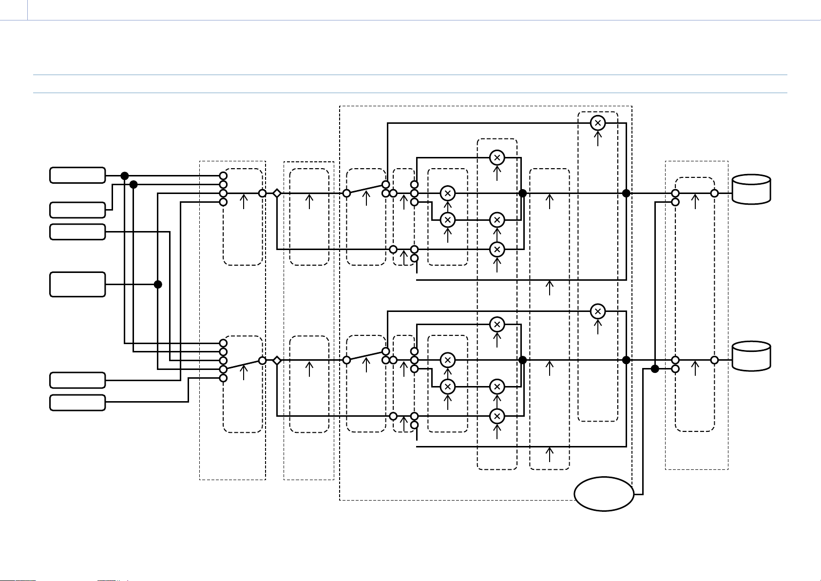
8. Appendix: Block Diagrams
132
Audio Input (CH3&CH4)
CH3
[CH3 Level
Control]*
Auto
Manual
[CH4 Level
Control]*
Auto
Manual
<CH3 INPUT LEVEL>
0 ~ 10
CH4
<CH4 INPUT LEVEL>
0 ~ 10
[CH3&4 AGC Mode]
Mono
Stereo
[Audio Input Level]
0 ~ 99
[Limiter Mode]
O, -6dB,
-9dB, -12dB,
-15dB, -17dB
SG
OFF
[CH3 Input Select]
O
INPUT1
Internal MIC
Shoe CH1
[CH3 Wind Filter]
On
O
[CH4 Wind Filter]
On
O
[CH4 Input Select]
O
INPUT1
INPUT2
Internal MIC
Shoe CH2
INPUT1
INPUT2
Shoe CH1
Shoe CH2
Internal MIC
[CH3 Level]
Audio Input Level
Side
Level + Side
Through
[CH4 Level]
Audio Input Level
Side
Level + Side
Through
[Color Bars]
[1kHz Tone on Color
Bars]
On
O
For XLR adaptorFor XLR adaptor
(Monaural)
* Set to Manual when audio is input from XLR adaptor.
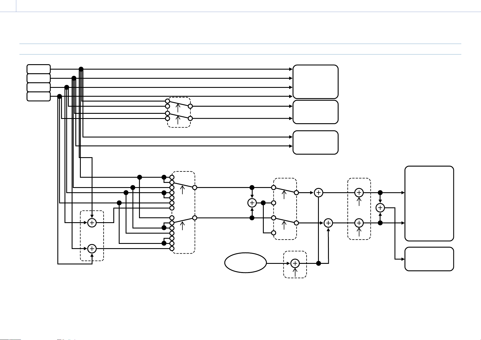
8. Appendix: Block Diagrams
133
Audio Output
Alarm
Beep
[HDMI Output CH]
CH1/CH2, CH3/CH4
[Monitor CH]
CH1, CH2, CH3, CH4,
CH1/CH2, CH3/CH4,
MIX ALL
[Headphone Out]
Mono, Stereo
<VOLUME>
0 ~ 50
L
R
[Alarm Level]
0 ~ 7
Ch
MIX
CH1
SDI OUT
Headphone
Internal Speaker
HDMI OUT
QoS
Streaming
CH2
CH3
CH4

8. Appendix
134
You can update the software of an E-mount
lens using the camcorder.
Refer to the web site for the lens for lenses
that can be updated and the corresponding
software.
Checking the Version
1 Attach an E-mount lens to the camcorder
(page 20).
2 Select Version in the Maintenance menu
to display Lens Version Number
(page 107).
The software version number of the
E-mount lens is displayed on the side.
Updating Software
Set the camcorder to mass storage mode
(page 112).
Update the software following the procedure
supplied with the lens software.
Updating E-mount Lens Software

8. Appendix
135
MPEG-4 Visual Patent Portfolio
License
THIS PRODUCT IS LICENSED UNDER THE MPEG-
4 VISUAL PATENT PORTFOLIO LICENSE FOR THE
PERSONAL AND NON-COMMERCIAL USE OF A
CONSUMER FOR
(i) ENCODING VIDEO IN COMPLIANCE WITH
THE MPEG-4 VISUAL STANDARD (“MPEG-4
VIDEO”) AND/OR
(ii) DECODING MPEG-4 VIDEO THAT WAS
ENCODED BY A CONSUMER ENGAGED IN
A PERSONAL AND NON-COMMERCIAL
ACTIVITY AND/OR WAS OBTAINED FROM A
VIDEO PROVIDER LICENSED BY MPEG LA TO
PROVIDE MPEG-4 VIDEO.
NO LICENSE IS GRANTED OR SHALL BE
IMPLIED FOR ANY OTHER USE. ADDITIONAL
INFORMATION INCLUDING THAT RELATING TO
PROMOTIONAL, INTERNAL AND COMMERCIAL
USES AND LICENSING MAY BE OBTAINED FROM
MPEG LA, LLC. SEE HTTP://WWW.MPEGLA.
COM
Obtaining Software Under the
GPL/LGPL License
This product uses software to which the
GPL/ LGPL applies. This informs you that you
have a right to have access to, modify, and
redistribute source code for these software
programs under the conditions of the GPL/
LGPL.
The source code is provided on the internet.
Use the following URL and follow the
download instructions.
http://www.sony.net/Products/Linux/
common/search.html
We would prefer that you do not contact us
about the contents of the source code.
Licenses (in English) are recorded in the
internal memory of your product.
Establish a Mass Storage connection between
the product and a computer to read licenses in
the “PMHOME” - “LICENSE” folder.
END USER LICENSE AGREEMENT
IMPORTANT:
BEFORE USING THE SOFTWARE CONTAINED IN THE
SOLID STATE MEMORY CAMCORDER, PLEASE READ THIS
END USER LICENSE AGREEMENT (“EULA”) CAREFULLY. BY
USING THE SOFTWARE YOU ARE ACCEPTING THE TERMS
OF THIS EULA. IF YOU DO NOT ACCEPT THE TERMS OF
THIS EULA, YOU MAY NOT USE THE SOFTWARE.
This EULA is a legal agreement between you and Sony
Corporation (“SONY”). This EULA governs your rights
and obligations regarding the software of SONY and/or
its third party licensors (including SONY’s affiliates) and
their respective affiliates (collectively, the “THIRD-PARTY
SUPPLIERS”) contained in the wireless adapter, together
with any updates/ upgrades provided by SONY, any
printed, on-line or other electronic documentation for
such software, and any data files created by operation of
such software (collectively, the “SOFTWARE”).
Notwithstanding the foregoing, any software in
the SOFTWARE having a separate end user license
agreement (including, but not limited to, GNU General
Public license and Lesser/Library General Public License)
shall be covered by such applicable separate end user
license agreement in lieu of the terms of this EULA to
the extent required by such separate end user license
agreement (“EXCLUDED SOFTWARE”).
SOFTWARE LICENSE
The SOFTWARE is licensed, not sold. The SOFTWARE is
protected by copyright and other intellectual property
laws and international treaties.
COPYRIGHT
All right and title in and to the SOFTWARE (including,
but not limited to, any images, photographs, animation,
video, audio, music, text and “applets” incorporated into
the SOFTWARE) is owned by SONY or one or more of the
THIRD-PARTY SUPPLIERS.
GRANT OF LICENSE
SONY grants you a limited license to use the SOFTWARE
solely in connection with the wireless adapter and only
for your individual use. SONY and the THIRD-PARTY
SUPPLIERS expressly reserve all rights, title and interest
(including, but not limited to, all intellectual property
rights) in and to the SOFTWARE that this EULA does not
specifically grant to you.
REQUIREMENTS AND LIMITATIONS
You may not copy, publish, adapt, redistribute, attempt
to derive source code, modify, reverse engineer,
decompile, or disassemble any of the SOFTWARE,
whether in whole or in part, or create any derivative
works from or of the SOFTWARE unless such derivative
works are intentionally facilitated by the SOFTWARE.
You may not modify or tamper with any digital rights
management functionality of the SOFTWARE. You
may not bypass, modify, defeat or circumvent any of
the functions or protections of the SOFTWARE or any
mechanisms operatively linked to the SOFTWARE. You
may not separate any individual component of the
SOFTWARE for use on more than one wireless adapter
unless expressly authorized to do so by SONY. You
may not remove, alter, cover or deface any trademarks
or notices on the SOFTWARE. You may not share,
distribute, rent, lease, sublicense, assign, transfer or
sell the SOFTWARE. The software, network services
or other products other than SOFTWARE upon which
the SOFTWARE’S performance depends might be
interrupted or discontinued at the discretion of the
suppliers (software suppliers, service suppliers, or
SONY). SONY and such suppliers do not warrant that the
SOFTWARE, network services, contents or other products
will continue to be available, or will operate without
interruption or modification.
EXCLUDED SOFTWARE AND OPEN SOURCE
COMPONENTS
Notwithstanding the foregoing limited license grant,
you acknowledge that the SOFTWARE may include
EXCLUDED SOFTWARE. Certain EXCLUDED SOFTWARE
may be covered by open source software licenses
(“Open Source Components”), which means any
software licenses approved as open source licenses by
the Open Source Initiative or any substantially similar
licenses, including but not limited to any license that,
as a condition of distribution of the software licensed
under such license, requires that the distributor make
the software available in source code format. If and to
the extent disclosure is required, please visit www.sony.
com/linux or other SONY-designated web site for a list
of applicable OPEN SOURCE COMPONENTS included in
the SOFTWARE from time to time, and the applicable
terms and conditions governing its use. Such terms
and conditions may be changed by the applicable
third party at any time without liability to you. To the
extent required by the licenses covering EXCLUDED
SOFTWARE, the terms of such licenses will apply in lieu
of the terms of this EULA. To the extent the terms of the
licenses applicable to EXCLUDED SOFTWARE prohibit
any of the restrictions in this EULA with respect to such
EXCLUDED SOFTWARE, such restrictions will not apply
to such EXCLUDED SOFTWARE. To the extent the terms
of the licenses applicable to Open Source Components
require SONY to make an offer to provide source code
in connection with the SOFTWARE, such offer is hereby
made.
USE OF SOFTWARE WITH COPYRIGHTED
MATERIALS
The SOFTWARE may be capable of being used by you
to view, store, process and/or use content created by
you and/or third parties. Such content may be protected
by copyright, other intellectual property laws, and/
or agreements. You agree to use the SOFTWARE only
in compliance with all such laws and agreements that
apply to such content. You acknowledge and agree
that SONY may take appropriate measures to protect
the copyright of content stored, processed or used by
the SOFTWARE. Such measures include, but are not
limited to, counting the frequency of your backup and
restoration through certain SOFTWARE features, refusal
to accept your request to enable restoration of data, and
Licenses

8. Appendix: Licenses
136
termination of this EULA in the event of your illegitimate
use of the SOFTWARE.
CONTENT SERVICE
PLEASE ALSO NOTE THAT THE SOFTWARE MAY BE
DESIGNED TO BE USED WITH CONTENT AVAILABLE
THROUGH ONE OR MORE CONTENT SERVICES
(“CONTENT SERVICE”). USE OF THE SERVICE AND THAT
CONTENT IS SUBJECT TO THE TERMS OF SERVICE OF
THAT CONTENT SERVICE. IF YOU DECLINE TO ACCEPT
THOSE TERMS, YOUR USE OF THE SOFTWARE WILL
BE LIMITED. You acknowledge and agree that certain
content and services available through the SOFTWARE
may be provided by third parties over which SONY has
no control. USE OF THE CONTENT SERVICE REQUIRES AN
INTERNET CONNECTION. THE CONTENT SERVICE MAY BE
DISCONTINUED AT ANY TIME.
INTERNET CONNECTIVITY AND THIRD PARTY
SERVICES
You acknowledge and agree that access to certain
SOFTWARE features may require an Internet connection
for which you are solely responsible. Further, you are
solely responsible for payment of any third party fees
associated with your Internet connection, including
but not limited to Internet service provider or airtime
charges. Operation of the SOFTWARE may be limited
or restricted depending on the capabilities, bandwidth
or technical limitations of your Internet connection
and service. The provision, quality and security of such
Internet connectivity are the sole responsibility of the
third party providing such service.
EXPORT AND OTHER REGULATIONS
You agree to comply with all applicable export and re-
export restrictions and regulations of the area or country
in which you reside, and not to transfer, or authorize
the transfer, of the SOFTWARE to a prohibited country
or otherwise in violation of any such restrictions or
regulations.
HIGH RISK ACTIVITIES
The SOFTWARE is not fault-tolerant and is not designed,
manufactured or intended for use or resale as on-
line control equipment in hazardous environments
requiring fail-safe performance, such as in the
operation of nuclear facilities, aircraft navigation or
communication systems, air traffic control, direct life
support machines, or weapons systems, in which the
failure of the SOFTWARE could lead to death, personal
injury, or severe physical or environmental damage
(“HIGH RISK ACTIVITIES”). SONY, each of the THIRD-
PARTY SUPPLIERS, and each of their respective affiliates
specifically disclaim any express or implied warranty,
duty or condition of fitness for HIGH RISK ACTIVITIES.
EXCLUSION OF WARRANTY ON SOFTWARE
You acknowledge and agree that use of the SOFTWARE
is at your sole risk and that you are responsible for use
of the SOFTWARE. The SOFTWARE is provided “AS IS,”
without warranty, duty or condition of any kind.
SONY AND EACH OF THE THIRD-PARTY SUPPLIERS (for
purposes of this Section, SONY and each of the THIRD-
PARTY SUPPLIERS shall be collectively referred to as
“SONY”) EXPRESSLY DISCLAIM ALL WARRANTIES, DUTIES
OR CONDITIONS, EXPRESS OR IMPLIED, INCLUDING,
BUT NOT LIMITED TO, THE IMPLIED WARRANTIES
OF MERCHANTABILITY, NONINFRINGEMENT AND
FITNESS FOR A PARTICULAR PURPOSE. SONY
DOES NOT WARRANT OR MAKE ANY CONDITIONS
OR REPRESENTATIONS (A) THAT THE FUNCTIONS
CONTAINED IN ANY OF THE SOFTWARE WILL MEET YOUR
REQUIREMENTS OR THAT THEY WILL BE UPDATED, (B)
THAT THE OPERATION OF ANY OF THE SOFTWARE WILL
BE CORRECT OR ERROR-FREE OR THAT ANY DEFECTS
WILL BE CORRECTED, (C) THAT THE SOFTWARE WILL
NOT DAMAGE ANY OTHER SOFTWARE, HARDWARE OR
DATA, (D) THAT ANY SOFTWARE, NETWORK SERVICES
(INCLUDING THE INTERNET) OR PRODUCTS (OTHER
THAN THE SOFTWARE) UPON WHICH THE SOFTWARE’S
PERFORMANCE DEPENDS WILL CONTINUE TO BE
AVAILABLE, UNINTERRUPTED OR UNMODIFIED, AND
(E) REGARDING THE USE OR THE RESULTS OF THE USE
OF THE SOFTWARE IN TERMS OF ITS CORRECTNESS,
ACCURACY, RELIABILITY, OR OTHERWISE.
NO ORAL OR WRITTEN INFORMATION OR ADVICE
GIVEN BY SONY OR AN AUTHORIZED REPRESENTATIVE
OF SONY SHALL CREATE A WARRANTY, DUTY OR
CONDITION OR IN ANY WAY INCREASE THE SCOPE OF
THIS WARRANTY. SHOULD THE SOFTWARE PROVE
DEFECTIVE YOU ASSUME THE ENTIRE COST OF ALL
NECESSARY SERVICING, REPAIR OR CORRECTION. SOME
JURISDICTIONS DO NOT ALLOW THE EXCLUSION OF
IMPLIED WARRANTIES, SO THESE EXCLUSIONS MAY NOT
APPLY TO YOU.
LIMITATION OF LIABILITY
SONY AND EACH OF THE THIRD-PARTY SUPPLIERS (for
purposes of this Section, SONY and each of the THIRD-
PARTY SUPPLIERS shall be collectively referred to as
“SONY”) SHALL NOT BE LIABLE FOR ANY INCIDENTAL
OR CONSEQUENTIAL DAMAGES FOR BREACH OF
ANY EXPRESS OR IMPLIED WARRANTY, BREACH OF
CONTRACT, NEGLIGENCE, STRICT LIABILITY OR UNDER
ANY OTHER LEGAL THEORY RELATED TO THE SOFTWARE,
INCLUDING, BUT NOT LIMITED TO, ANY DAMAGES
ARISING OUT OF LOSS OF PROFITS, LOSS OF REVENUE,
LOSS OF DATA, LOSS OF USE OF THE SOFTWARE OR
ANY ASSOCIATED HARDWARE, DOWN TIME AND USER'S
TIME, EVEN IF ANY OF THEM HAVE BEEN ADVISED OF
THE POSSIBILITY OF SUCH DAMAGES. IN ANY CASE,
EACH AND ALL OF THEIR AGGREGATE LIABILITY UNDER
ANY PROVISION OF THIS EULA SHALL BE LIMITED TO
THE AMOUNT ACTUALLY PAID FOR THE PRODUCT.
SOME JURISDICTIONS DO NOT ALLOW THE EXCLUSION
OR LIMITATION OF INCIDENTAL OR CONSEQUENTIAL
DAMAGES, SO THE ABOVE EXCLUSION OR LIMITATION
MAY NOT APPLY TO YOU.
CONSENT TO USE OF NON-PERSONAL
INFORMATION, LOCATION DATA, DATA
SECURITY
You acknowledge and agree that SONY and its
affiliates, partners and agents may read, collect,
transfer, process and store certain information
collected from the SOFTWARE, including but not
limited to information about (i) the SOFTWARE and
(ii) the software applications, contents and peripheral
devices that interact with your wireless adapter and the
SOFTWARE (“Information”). Information includes, but
is not limited to: (1) unique identifiers relating to your
wireless adapter and its components; (2) performance
of the wireless adapter, the SOFTWARE and their
components; (3) configurations of your wireless adapter,
the SOFTWARE and the software applications, contents
and peripheral devices that interact with the wireless
adapter and the SOFTWARE; (4) use and frequency of
use of the functions of (x) the SOFTWARE, and (y) the
software applications, contents and peripheral devices
that interact with the SOFTWARE; and (5) location data,
as indicated below. SONY and its affiliates, partners
and agents may use and disclose Information subject
to applicable laws in order to improve its products and
services or to provide products or services to you. Such
uses include, but are not limited to: (a) administering
the functionalities of the SOFTWARE; (b) to improve,
service, update or upgrade the SOFTWARE; (c)
improving, developing and enhancing the current and
future products and services of SONY and other parties;
(d) to provide you with information about the products
and services offered by SONY and other parties; (e)
complying with applicable laws or regulations; and (f)
to the extent offered, providing you with location-based
services of SONY and other parties, as indicated below.
In addition, SONY retains the right to use Information
to protect itself and third parties from illegal, criminal or
harmful conduct.
Certain services available through the SOFTWARE may
rely upon location information, including, but not limited
to, the geographic location of the wireless adapter. You
acknowledge that for the purpose of providing such
services, SONY, the THIRDPARTY SUPPLIERS or their
partners may collect, archive, process and use such
location data, and that such services are governed by
the privacy policies of SONY or such third party. By
reviewed the privacy policies applicable to such services
and consent to such activities.
SONY, its affiliates, partners and agents will not
intentionally use Information to personally identify
the owner or user of the SOFTWARE without your
knowledge or consent. Any use of Information will be
in accordance with the privacy policies of SONY or such
third party.
Please contact applicable contact address of each area or
country for SONY’s current privacy policy. Please contact
applicable third parties for privacy policies relating
to personally identifiable and other information you
provide when you use or access third party software or
services.
Information may be processed, stored or transferred
to SONY, its affiliates or agents which are located in
countries outside of your country of residence. Data

8. Appendix: Licenses
137
protection and information privacy laws in certain
countries may not offer the same level of protection
as your country of residence and you may have fewer
legal rights in relation to Information processed and
stored in, or transferred to, such countries. SONY will
use reasonable efforts to take appropriate technical and
organizational steps to prevent unauthorized access to
or disclosure of Information, but does not warrant it will
eliminate all risk of misuse of such Information.
AUTOMATIC UPDATE FEATURE
From time to time, SONY or the THIRD-PARTY SUPPLIERS
may automatically update or otherwise modify the
SOFTWARE, including, but not limited to, for purposes
of enhancement of security functions, error correction
and improvement of functions, at such time as you
interact with SONY’s or third parties’ servers, or
otherwise. Such updates or modifications may delete
or change the nature of features or other aspects of the
SOFTWARE, including, but not limited to, functions you
may rely upon. You acknowledge and agree that such
activities may occur at SONY’s sole discretion and that
SONY may condition continued use of the SOFTWARE
upon your complete installation or acceptance of such
update or modifications. Any updates/modifications
shall be deemed to be, and shall constitute part of, the
SOFTWARE for purposes of this EULA. By acceptance of
this EULA, you consent to such update/modification.
ENTIRE AGREEMENT, WAIVER, SEVERABILITY
This EULA and SONY’s privacy policy, each as amended
and modified from time to time, together constitute the
entire agreement between you and SONY with respect
to the SOFTWARE. The failure of SONY to exercise or
enforce any right or provision of this EULA shall not
constitute a waiver of such right or provision. If any part
of this EULA is held invalid, illegal, or unenforceable,
that provision shall be enforced to the maximum extent
permissible so as to maintain the intent of this EULA,
and the other parts will remain in full force and effect.
GOVERNING LAW AND JURISDICTION
The United Nations Convention on Contracts for the
International Sale of Goods shall not apply to this EULA.
This EULA shall be governed by the laws of Japan,
without regards to conflict of laws provisions. Any
dispute arising out of this EULA shall be subject to the
exclusive venue of the Tokyo District Court in Japan, and
the parties hereby consent to the venue and jurisdiction
of such courts.
EQUITABLE REMEDIES
Notwithstanding anything contained in this EULA to the
contrary, you acknowledge and agree that any violation
of or noncompliance with this EULA by you will cause
irreparable harm to SONY, for which monetary damages
would be inadequate, and you consent to SONY
obtaining any injunctive or equitable relief that SONY
deems necessary or appropriate in such circumstances.
SONY may also take any legal and technical remedies
to prevent violation of and/or to enforce this EULA,
including, but not limited to, immediate termination of
your use of the SOFTWARE, if SONY believes in its sole
discretion that you are violating or intend to violate
this EULA. These remedies are in addition to any other
remedies SONY may have at law, in equity or under
contract.
TERMINATION
Without prejudice to any of its other rights, SONY may
terminate this EULA if you fail to comply with any of its
terms. In case of such termination, you must: (i) cease
all use, and destroy any copies, of the SOFTWARE; (ii)
comply with the requirements in the section below
entitled “Your Account Responsibilities”.
AMENDMENT
SONY RESERVES THE RIGHT TO AMEND ANY OF THE
TERMS OF THIS EULA AT ITS SOLE DISCRETION BY
POSTING NOTICE ON A SONY DESIGNATED WEB SITE, BY
EMAIL NOTIFICATION TO AN EMAIL ADDRESS PROVIDED
BY YOU, BY PROVIDING NOTICE AS PART OF THE
PROCESS IN WHICH YOU OBTAIN UPGRADES/ UPDATES
OR BY ANY OTHER LEGALLY RECOGNIZABLE FORM OF
NOTICE. If you do not agree to the amendment, you
should promptly contact SONY for instructions. Your
continued use of the SOFTWARE after the effective date
of any such notice shall be deemed your agreement to
be bound by such amendment.
THIRD-PARTY BENEFICIARIES
Each THIRD-PARTY SUPPLIER is an express intended
thirdparty beneficiary of, and shall have the right to
enforce, each provision of this EULA with respect to the
SOFTWARE of such party.
Should you have any questions concerning this EULA,
you may contact SONY by writing to SONY at applicable
contact address of each area or country.
Copyright © 2012 Sony Corporation.
Open Source Software Licenses
On the basis of license contracts between
Sony and the software copyright holders, this
product uses open software.
To meet the requirements of the software
copyright holders, Sony is obligated to inform
you of the content of these licenses.
Licenses (in English) are recorded in the
internal memory of your product.
Establish a Mass Storage connection between
the product and a computer to read licenses in
the “PMHOME” - “LICENSE” folder.

8. Appendix
138
General
Mass Approx. 2.3 kg (5 lb 1 oz) (body,
including handle)
Dimensions
(Unit: mm (inch), body, including
handle)
1)
159.5
(6
3
/
8
)
246
(9
3
/
4
)
257 (10
1
/
8
)
216 (8
5
/
8
)
229 (9
1
/
8
)
146
(5
3
/
4
)
142.5
(5
5
/
8
)
1) The values for dimensions are approximate.
Power requirements
19.5 V DC (18.0 V to 20.5 V)
Power consumption
Approx. 35.2 W (body, lens, XAVC-I
QFHD 59.94P recording,
viewfinder on, no external device
connected)
Approx. 36.8 W (body, lens, XAVC-I
QFHD 59.94P recording,
viewfinder on, 3G-SDI×2, HDMI,
external device connected)
Operating temperature
0 °C to 40 °C (32 °F to 104 °F)
Storage temperature
–20 °C to +60 °C (–4 °F to +140 °F)
Continuous operating time
Approx. 54 minutes (using BP-U35)
(body, lens, XAVC-I QFHD 59.94P
recording, viewfinder on, no
external device connected)
Recording format (video)
XAVC Intra
XAVC-I QFHD mode: CBG, 600 Mbps
(max), MPEG-4 AVC/H.264
XAVC-I HD mode: CBG, 223 Mbps
(max), MPEG-4 AVC/H.264
XAVC Long
XAVC-L QFHD mode: VBR, 150 Mbps
(max), MPEG-4 H.264/AVC
XAVC-L HD 50 mode: VBR, 50 Mbps
(max), MPEG-4 H.264/AVC
XAVC-L HD 35 mode: VBR, 35 Mbps
(max), MPEG-4 H.264/AVC
XAVC-L HD 25 mode: VBR, 25 Mbps
(max), MPEG-4 H.264/AVC
MPEG-2 Long GOP
MPEG HD422 mode: CBR, 50 Mbps
(max), MPEG-2 422P@HL
Recording format (audio)
LPCM 24-bit, 48 kHz, 4-channel
Recording frame rate
XAVC Intra
XAVC-I QFHD mode:
3840×2160/59.94P, 50P, 29.97P,
23.98P, 25P
XAVC-I HD mode: 1920×1080/59.94P,
50P, 59.94i, 50i, 29.97P, 23.98P,
25P
XAVC Long
XAVC-L QFHD mode:
3840×2160/59.94P, 50P, 29.97P,
23.98P, 25P
XAVC-L HD 50 mode:
1920×1080/59.94P, 50P, 59.94i,
50i, 29.97P, 23.98P, 25P
XAVC-L HD 35 mode:
1920×1080/59.94P, 50P, 59.94i,
50i, 29.97P, 23.98P, 25P
XAVC-L HD 25 mode:
1920×1080/59.94i, 50i
MPEG-2 Long GOP
MPEG HD422 mode:
1920×1080/59.94i, 50i, 29.97P,
23.98P, 25P
Recording/playback time
XAVC Intra
XAVC-I QFHD mode:
59.94P
Approx. 22 minutes (using
QD-G128E/QD-G120F)
XAVC-I HD mode:
59.94P
Approx. 57 minutes (using
QD-G128E/QD-G120F)
XAVC Long
XAVC-L QFHD mode:
59.94P
Approx. 86 minutes (using
QD-G128E/G120F)
XAVC-L HD 50 mode:
59.94P
Approx. 110 minutes (using
QD-G64E)
XAVC-L HD 35 mode:
59.94P
Approx. 150 minutes (using
QD-G64E)
XAVC-L HD 25 mode:
59.94i
Approx. 200 minutes (using
QD-G64E)
MPEG-2 Long GOP
MPEG HD422 mode:
59.94i
Approx. 105 minutes (using
QD-G64E)
[Note]
The recording/playback time may vary due to usage
conditions and memory characteristics. The recording
and playback times are for a continuous recording as a
single clip. The actual times may be shorter, depending
on the number of clips recorded.
Camera Section
Imaging device (type)
35mm full-frame, single-chip CMOS image
sensor
Number of pixels
20.5M (total)
Auto focus
Detection method: Phase detection/contrast
detection
Internal ND filters
CLEAR: OFF
1: 1/4ND
2: 1/16ND
3: 1/64ND
Linearly variable ND: 1/4ND to 1/128ND
ISO sensitivity
ISO 800/4000 (Cine EI mode, D55 Light
source)
Lens mount
E-mount (lever lock type)
Latitude
15+ stops
Video S/N
57 dB (Y) (Typical)
Shutter speed
64F to 1/8000 sec. (23.98P)
Specifications

8. Appendix: Specifications
139
Shutter angle
5.6° to 360°, 2 to 64 frames
Slow & Quick Motion
XAVC QFHD: 1 to 60P, XAVC HD: 1 to 120P
White balance
2000K to 15000K
Gain
–3 dB to +18 dB (1 dB units)
Gamma curve
S-Cinetone, STD1, STD2, STD3, STD4, STD5,
STD6, HG1, HG2, HG3, HG4, HG7,
HG8, S-Log3
Audio Section
Sampling frequency
48 kHz
Quantization
24-bit
Frequency response
XLR input MIC mode: 20 Hz to 20 kHz
(±3 dB or less)
XLR input LINE mode: 20 Hz to 20 kHz
(±3 dB or less)
Dynamic range
XLR input MIC mode: 80 dB (Typical)
XLR input LINE mode: 90 dB (Typical)
Distortion
XLR input MIC mode: 0.08% or lower
(–40dBu input level)
XLR input LINE mode: 0.08% or lower
(+14dBu input level)
Built-in speaker
Monaural
Internal microphone
Monaural
Input/Output Section
Inputs
INPUT 1/2:
XLR type, 3-pin, female
LINE / MIC / MIC+48V switchable
MIC: Reference –30 dBu to –80 dBu
GENLOCK IN:
BNC type
TC IN:
BNC type
Outputs
SDI OUT1:
BNC type, 12G-SDI, 3G-SDI (Level A/B), HD-SDI
SDI OUT2:
BNC type, 3G-SDI (Level A/B), HD-SDI
Headphones (stereo mini jack):
–16 dBu (reference level output, maximum
monitor volume, 16 Ω load)
HDMI:
Type A, 19-pin
REF OUT:
BNC type
TC OUT:
BNC type
Other
DC IN:
EIAJ compliant, 18 V to 20.5 V DC
Extension unit connector:
Dedicated (144-pin)
Multi-interface shoe:
Dedicated (21-pin)
REMOTE:
2.5 mm 3-pole sub-mini type
USB/multi:
USB 2.0 standard compliant, micro B type for
mass storage (1)
VF:
Dedicated (40-pin)
Display Section
Viewfinder (LCD)
Screen size
8.8 cm (3.5 inch) diagonal
Aspect ratio
16:9
Number of pixels
1280 (H) × 720 (V)
Media Slot Section
XQD card slots for video recording (2)
UTILITY SD/MS card slot (1)
Supplied Accessories
AC adaptor (1)
Power cord (1)
Battery charger (1)
Handle (1)
LCD monitor (1)
Eyepiece (1)
USB cable (1)
Grip remote control (1)
Lens mount cap (1)
Handle connector protective cap (1)
Grip attachment cover (1)
Before Using This Unit (1)
Operating Instructions (CD-ROM) (1)
Warranty booklet (1)
Design and specifications are subject to
change without notice.
Notes
Always make a test recording, and verify
that it was recorded successfully. SONY
WILL NOT BE LIABLE FOR DAMAGES OF
ANY KIND INCLUDING, BUT NOT LIMITED
TO, COMPENSATION OR REIMBURSEMENT
ON ACCOUNT OF FAILURE OF THIS UNIT
OR ITS RECORDING MEDIA, EXTERNAL
STORAGE SYSTEMS OR ANY OTHER
MEDIA OR STORAGE SYSTEMS TO RECORD
CONTENT OF ANY TYPE.
Always verify that the unit is operating
properly before use. SONY WILL NOT
BE LIABLE FOR DAMAGES OF ANY
KIND INCLUDING, BUT NOT LIMITED TO,
COMPENSATION OR REIMBURSEMENT ON
ACCOUNT OF THE LOSS OF PRESENT OR
PROSPECTIVE PROFITS DUE TO FAILURE OF
THIS UNIT, EITHER DURING THE WARRANTY
PERIOD OR AFTER EXPIRATION OF THE
WARRANTY, OR FOR ANY OTHER REASON
WHATSOEVER.
SONY WILL NOT BE LIABLE FOR CLAIMS OF
ANY KIND MADE BY USERS OF THIS UNIT
OR MADE BY THIRD PARTIES.
SONY WILL NOT BE LIABLE FOR THE LOSS,
REPAIR, OR REPRODUCTION OF ANY DATA
RECORDED ON THE INTERNAL STORAGE
SYSTEM, RECORDING MEDIA, EXTERNAL
STORAGE SYSTEMS OR ANY OTHER MEDIA
OR STORAGE SYSTEMS.
SONY WILL NOT BE LIABLE FOR THE
TERMINATION OR DISCONTINUATION OF
ANY SERVICES RELATED TO THIS UNIT THAT
MAY RESULT DUE TO CIRCUMSTANCES OF
ANY KIND.

8. Appendix: Specifications
140
Software Downloads
When the unit is used with a PC connection,
download device drivers, plug-ins, and
application software, where applicable, from
the Sony Professional products web site.
Sony Professional products web site
homepage:
U.S.A. http://pro.sony.com
Canada http://www.sonybiz.ca
Latin America http://sonypro-latin.com
Europe http://www.pro.sony.eu/pro
Middle East and Africa
http://sony-psmea.com
Russia http://sony.ru/pro/
Brazil http://sonypro.com.br
Australia http://pro.sony.com.au
New Zealand http://pro.sony.co.nz
Japan http://www.sonybsc.com
Asia Pacific http://pro.sony-asia.com
Korea http://bp.sony.co.kr
China http://pro.sony.com.cn
India http://pro.sony.co.in
Sony Creative Software, software download
page
http://www.sonycreativesoftware.com/
download/software_for_sony_equipment
Trademarks
XDCAM is a trademark of Sony Corporation.
XAVC and
are registered trademarks of
Sony Corporation.
XQD and
are trademarks of Sony
Corporation.
The terms HDMI and HDMI High-Definition
Multimedia Interface, and the HDMI Logo
are trademarks or registered trademarks of
HDMI Licensing Administrator, Inc. in the
United States and other countries.
Microsoft and Windows are trademarks
or registered trademarks of Microsoft
Corporation in the United States and/or
other countries.
Mac and Mac OS are registered trademarks
of Apple Inc. in the U.S. and other countries.
“Memory Stick”, “Memory Stick Duo,”
“Memory Stick PRO Duo,” “Catalyst Browse,”
“Content Browser Mobile,” and the “Content
Browser Mobile” logo are trademarks or
registered trademarks of Sony Corporation.
iOS is a registered trademark or trademark
of Cisco Systems, Inc. and/or its affiliates
in the United States and certain other
countries.
Android, Google Play are trademarks of
Google Inc.
Wi-Fi, the Wi-Fi logo, and Wi-Fi PROTECTED
SETUP are trademarks or registered
trademarks of Wi-Fi Alliance.
The N Mark is a trademark or registered
trademark of NFC Forum, Inc. in the United
States and in other countries.
All other company names and product names
are registered trademarks or trademarks of
their respective owners. Trademarked items
are not indicated by ™ or ® symbols in this
document.