Loading ...
Loading ...
Loading ...
en Installation instructions
42
An all-pole isolating switch must be integrated into the
permanent electrical installation according to the install-
ation regulations.
1.
Identify the phase and neutral conductors in the
socket.
The appliance may be damaged if it is not connec-
ted correctly.
2.
Connect the hob in accordance with the connection
diagram.
The yellow/green wire for the safety earth terminal
must be 10mm longer on the appliance side than
the other wires.
See the rating plate for the voltage.
Connection 3N~ / 2N~ / 1N~: Use a H05VV-F
mains power cable or one with a higher rating.
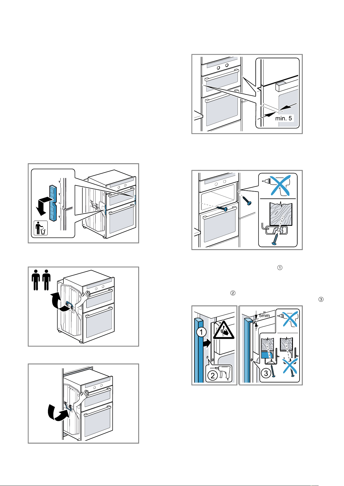
24.6 Installing the appliance
1.
Remove the transport locks on the right and left and
then dispose of them.
2.
The appliance must be transported by two people
using the carry handles on the right and left, while
securing the front of the appliance with one hand.
3.
Place the appliance in the unit and fold the carry
handles down.
4.
Push the appliance in fully.
Do not kink or trap the connection cable, or route it
over sharp edges.
5.
Centre the appliance.
There must be an air gap of at least 5mm between
the appliance and adjacent unit fronts.
6.
Use a spirit level to adjust the appliance so that it is
perfectly level.
7.
Screw the appliance into place.
8.
For handleless kitchens with vertical bar handle
strips:
‒ Attach a suitable filling piece in order to cover
any sharp edges and to guarantee a safe install-
ation.
‒ Pre-drill aluminium profiles to establish a screw
connection .
‒ Secure the appliance using a suitable screw .
24.7 Removing the appliance
1.
Disconnect the appliance from the power supply.
2.
Undo the fastening screws.
3.
Lift the appliance slightly and pull it out completely.
Loading ...
Loading ...