Loading ...
Loading ...
Loading ...

7
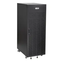
3. Battery Cabinet Installation
Read Section 2 – Important Safety
Instructions Before Installation
3.1 Preparation
• At your site, prepare to o-load the battery cabinet from the delivery truck and transport it to the nal installation
location. Consider both the packaged weight and dimensions.
• Make sure the oor can support the load of the specic battery cabinet being installed. The battery cabinet must
be installed in a structurally sound area with a level oor that is able to bear the weight of the battery cabinet and
other equipment that will be installed nearby.
• Draw a wiring schematic representing the cables connected between the battery cabinet’s output terminal blocks
and any external disconnect device, junction box and/or load/rectier.
• If you plan to store the battery cabinet for an extended period before or after installation, follow the instructions in
section 8. Storage and Service.
3.2 Transportation
1. Inspect the shipping container(s) for visible damage (do not remove the stretch wrap around the unit until it has
been transported to the nal installation location). Conrm that the model name and rating match the unit you
ordered. If you determine the unit has been damaged during shipping or if anything appears to be missing,
contact Eaton for assistance. Do not attempt to use the unit if it has been damaged or mishandled.
2. Do not attempt to move or unpack the battery cabinet without assistance. Use appropriate handling equipment
rated to bear the weight and bulk of the battery cabinet, such as freight elevators, pallet jacks and forklifts. (Fully
extend forks under load. Spread forks to maximum possible width under load. Lift cabinet from bottom only. Wear
safety shoes.) Conrm load limits for freight elevators, handling equipment and oors along the transport route
are not exceeded by the combined weight of the packaged battery cabinet, handling equipment and personnel.
Conrm that the packaged unit will pass through any doorways along the intended route.
3. The battery cabinet is secured with stretch wrap to protect it during shipping and movement within a facility.
Remove the stretch wrap from the battery cabinet when the unit is in the nal installation location—not before.
3.3 Mechanical Check
While the assembled cabinet battery system is still on the shipping pallet, inspect all sides for impact or other damage.
1. Open the front door of the battery cabinet.
2. Conrm none of the internal parts (batteries, terminal blocks, circuit breaker and other parts) have been damaged.
3. Note the individual battery model number and terminal type shown in section 7.Specications.
4. Use insulated tools to tighten all battery terminal connections to the recommended torque shown in the table in
section 5.3 Power Cables.
5. Use insulated tools to tighten the cables from the positive and negative output terminals at the end batteries to the
circuit breaker.
Loading ...
Loading ...
Loading ...