Loading ...
Loading ...
Loading ...

10
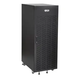
3. Battery Cabinet Installation
4. The top of the battery cabinet includes knockouts for load connection cable entry. Punch out the appropriate
knockout and connect the conduit or cable bushing.
5. The output circuit breaker accommodates cables up to 300 mm
2
.
6. Connect an appropriate equipment grounding cable to the grounding lug located on the top of the battery cabinet.
7. Feed the positive and negative cables (and “N” center, if equipped) from the open external disconnect switch or the
UPS battery eld wiring terminals through the conduit/cable bushing. Connect to the respective output terminals
inside the battery cabinet.
3.8 Final Electrical Check
Before closing any connecting circuit breaker or disconnect switch, complete these verication steps:
1. Verify the battery cabinet output voltage is correct.
2. If battery cabinets will be operated in parallel, verify that the individual system output voltages match within 2V DC.
3. Verify the voltage measured between either output terminal and the battery cabinet ground is zero.
4. If any of the above verication steps show an irregularity, determine and correct the cause before proceeding.
5. Reset the circuit breaker to the “On” position.
Loading ...
Loading ...
Loading ...