Loading ...
Loading ...
Loading ...
3.Junior User Guidebook
8. LAN port: the network port which can be used to connect with PC.
9. USB Device port: It is used to transfer data when external USB equipment connects
to the oscilloscope regarded as "slave device". For example: to use this port when
connect PC to the oscilloscope by USB.
10. Lock Hole: You can lock the oscilloscope to a fixed location using the security lock
(please buy it yourself) to secure the oscilloscope.
11. AV Port: AV signal output port (optional).
12. Trig Out(P/F) port: Trigger signal output or Pass/Fail output, also can be used as the
port of CH2 Output of optional dual-channel waveform generator. The output type can
be set on the menu (Utility menu→Output→Output).
13. Out 1 port: Output (single-channel) or CH1 Output (dual-channel) of optional
waveform generator.
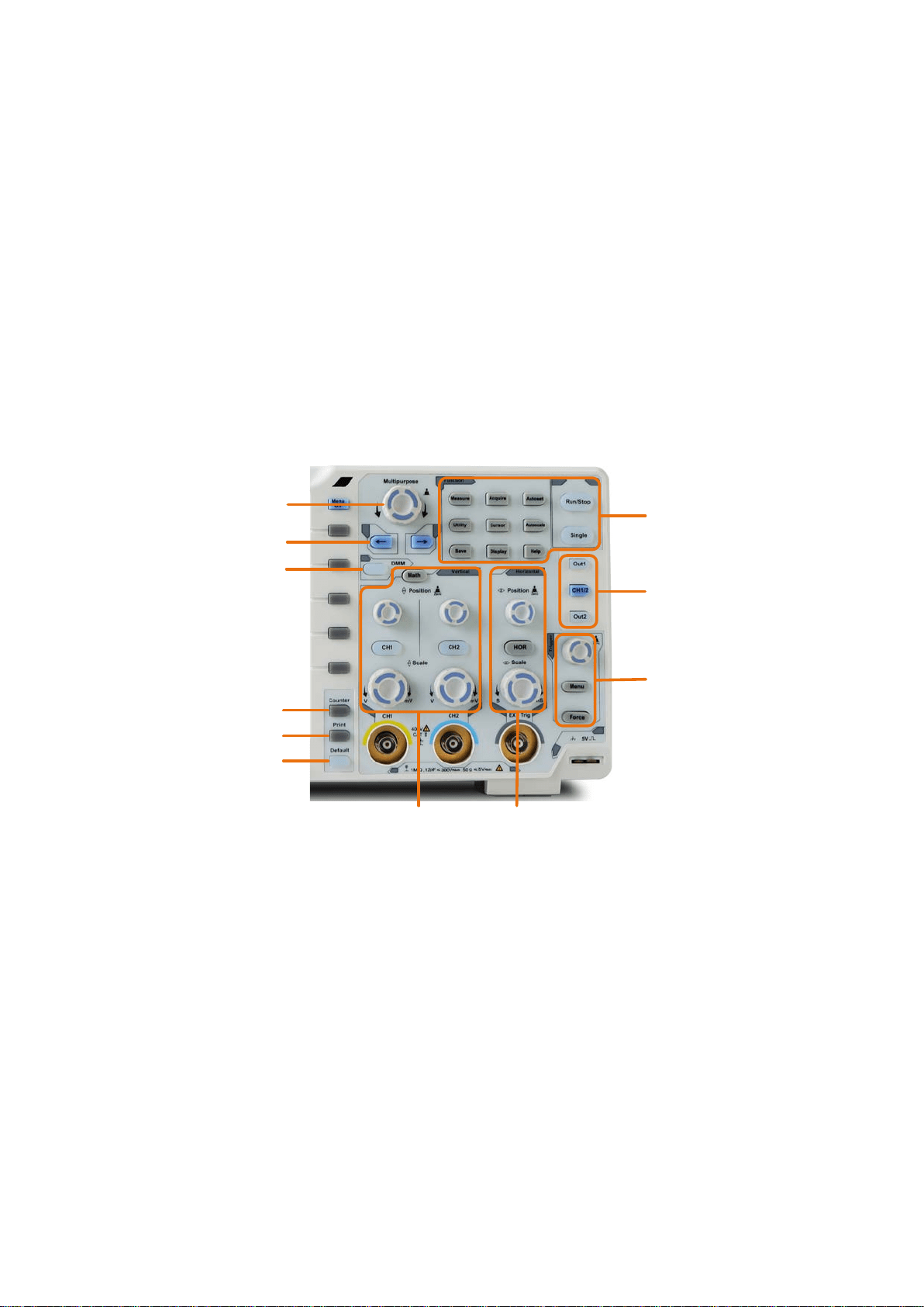
Control Area
8
7
6
1
2
3
11
10
5
4
9
Figure 3-4 Control Area Overview
1. Function button area: Total 11 buttons
2. Waveform generator controls (optional)
or
DAQ: Multimeter Recorder (see "Multimeter Recorder" on P111)
P/F: Pass/Fail (see "Pass/Fail" on P82)
W.REC: Waveform Record (see "How to Record/Playback Waveforms" on P73)
3. Trigger control area with 2 buttons and 1 knob.
The Trigger Level knob is to adjust trigger voltage. Other 2 buttons refer to trigger
system setting.
4. Horizontal control area with 1 button and 2 knobs.
"HOR" button refer to horizontal system setting menu, "Horizontal Position" knob
control trigger position, "Horizontal Scale" control time base.
7
Loading ...
Loading ...
Loading ...