VERSION A6
MPPT Solar Charge Controller
Rover Li Series
12V/24V 20A/30A/40A
USER MANUAL
Applicability
The user manual applies to the following products:
z
Rover Li 12V/24V 20A MPPT Solar Charge Controller (RNG-CTRL-RVR20)
z
Rover Li 12V/24V 30A MPPT Solar Charge Controller (RNG-CTRL-RVR30)
z
Rover Li 12V/24V 40A MPPT Solar Charge Controller (RNG-CTRL-RVR40)
Disclaimer
z
Renogy ensures the accuracy, sufficiency, and the applicability of information in the user
manual at the time of printing due to continual product improvements that may occur.
z
Renogy assumes no responsibility or liability for personal and property losses, whether
directly and indirectly, caused by the user’s failure to install and use the product in
compliance with the user manual.
z
Renogy is not responsible or liable for failures, damages, or injuries resulting from repair
attempted by unqualified personnel, improper installation and operation.
z
The illustrations in the user manual are for demonstration purposes only. Details may appear
slightly different depending on product revision and market region.
z
Renogy reserves the right to change the information in the user manual without notice. For
the latest user manual, visit
renogy.com.
Copyright
Rover Li Series MPPT Solar Charge Controller User Manual © 2022 Renogy. All rights reserved.
All information in the user manual is subject to copyright and other intellectual property rights
of Renogy and its licensors. The user manual may not be modified, reproduced, or copied, in
whole or in part, without the prior written permissions of Renogy and its licensors.
Trademark
The following are registered trademarks of Renogy:
RENOGY
The registered trademarks in the user manual are the property of Renogy. The unauthorized use
of the trademarks is strictly prohibited.
Date and Revision
January 2023, Revision A6

Table of Contents
Important Safety Information .......................................................................................................01
Symbols Used .........................................................................................................................01
General Safety Information .....................................................................................................01
Introduction ..................................................................................................................................03
General Information ................................................................................................................03
Key Features ...........................................................................................................................03
Charging and Activation Logic .....................................................................................................04
MPPT Technology ...................................................................................................................04
Four Charging Stages .............................................................................................................05
Lithium Battery Activation ........................................................................................................07
Package Contents .......................................................................................................................08
Optional Accessories ...................................................................................................................09
Product Overview ........................................................................................................................10
Wiring Diagram ............................................................................................................................ 11
Recommended Cable and Fuse Sizing .......................................................................................12
Recommended Cable Sizing ...................................................................................................12
Recommended Fuse Sizing ....................................................................................................13
Components & Tools ...................................................................................................................14
Preparation ..................................................................................................................................15
Inspection ................................................................................................................................15
Environment ............................................................................................................................15
Placement ...............................................................................................................................16
Checking Battery .....................................................................................................................17
Checking Solar Panel ..............................................................................................................18
Mounting ......................................................................................................................................20
Wall-mounted ..........................................................................................................................20

Mounting with Brackets ...........................................................................................................22
Installation ...................................................................................................................................24
Battery Wiring ..........................................................................................................................24
Solar Wiring .............................................................................................................................27
Load Wiring (Optional) ............................................................................................................30
Temperature Sensor ....................................................................................................................33
Bluetooth Module (Optional) ........................................................................................................34
Battery Type ................................................................................................................................36
Setting the Battery Type ..........................................................................................................36
Battery Charging Parameters ..................................................................................................37
User Mode ...............................................................................................................................38
System Voltage............................................................................................................................45
Monitoring ....................................................................................................................................47
Monitoring Menu .....................................................................................................................47
Checking Parameters ..............................................................................................................51
Load Control ................................................................................................................................52
Turning Load On / Off ..............................................................................................................52
Switching Load Mode ..............................................................................................................52
LED Indicators .............................................................................................................................55
Solar Panel LED Indicator .......................................................................................................55
Battery LED Indicator ..............................................................................................................56
Load LED Indicator .................................................................................................................56
System Error LED Indicator ....................................................................................................56
Troubleshooting ...........................................................................................................................57
Common Faults .......................................................................................................................57
Error Codes .............................................................................................................................59
Technical Specifications ..............................................................................................................62
MPPT Conversion Efficiency .......................................................................................................64

Dimensions ..................................................................................................................................65
RNG-CTRL-RVR20 .................................................................................................................65
RNG-CTRL-RVR30 or RNG-CTRL-RVR40 ............................................................................66
Maintenance ................................................................................................................................67
Inspection ................................................................................................................................67
Cleaning ..................................................................................................................................67
Storage ....................................................................................................................................67
Emergency Responses ...............................................................................................................68
Fire ..........................................................................................................................................68
Flooding ..................................................................................................................................68
Smell .......................................................................................................................................68
Noise .......................................................................................................................................68
Technical Support ........................................................................................................................69
01
Important Safety Information
The user manual provides important installation, operation, and maintenance instructions for
Rover Li Series Solar Charge Controller (hereinafter referred to as charge controller). Read the
user manual carefully before installation and operation and save it for future reference. Failure
to observe the instructions or precautions in the user manual can result in electrical shock,
serious injury, or death, or can damage the charge controller, potentially rendering it inoperable.
The installation and service of the charge controller might require knowledge of electricity and is
recommended to be carried out by qualified personnel.
Symbols Used
The following symbols are used throughout the user manual to highlight important information:
WARNIN
G
Indicates a potentially dangerous condition which could result in
injury or death
CAUTIO
N
Indicates a critical procedure for safe and proper installation and
operation
NOT
E
Indicates an important step or tip for optimal performance
INFO
Indicates that more information is available in other documents
relating to the subject
General Safety Information
WARNIN
G
z
Do not puncture, drop, crush, penetrate, shake, strike, or step on the charge controller.
z
Do not open, dismantle, repair, tamper with, or modify the components of the charge
controller.
z
Install the charge controller on a vertical surface indoors protected from direct sunlight, high
temperature, and water. Make sure there is good ventilation.
z
Do not immerse the charge controller or its components in water or other fluids.
z
Keep the charge controller away from heating equipment.
z
Do not insert foreign objects into the charge controller.
z
Risk of explosion! Never install the charge controller in a sealed enclosure with flooded
batteries! Do not install in a confined area where battery gases can accumulate.
z
Confirm the polarities of the devices before connection. A reverse polarity contact will result
in abnormalities.
z
Refer to
Recommended Cable and Fuse Sizing in this user manual, and select the
appropriate cables and fuses according to the usage.
z
Keep the charge controller out of the reach of children.
Important Safety Information
Symbols Used General Safety Information
02
Important Safety Information
z
Wear proper protective equipment and use insulated tools during installation and operation.
z
Do not touch the connector contacts when the charge controller is in operation.
z
Disconnect all connectors from the charge controller before maintenance or cleaning.
z
Do not dispose of the charge controller as household waste. Comply with local, state, and
federal laws and regulations and use recycling channels as required.
z
In the event of fire, use fire extinguishers suitable for electrical equipment.
z
If the charge controller is installed improperly on a boat, it may cause damage to the
corrosive agents of the boat. Please have the charge controller by a qualified electrician.
CAUTIO
N
z
Do not expose the charge controller to flammable or harsh chemicals or vapors.
z
Ensure that there is no water source including downspouts, sprinkles, or faucets above or
near the charge controller.
z
Ensure that the battery pack is properly connected before installation.
Symbols Used General Safety Information
03
Introduction
Introduction
General Information
Rover Li Series MPPT Solar Charge Controller can serve various off-grid solar systems. With the
adoption of intelligent MPPT (Maximum Power Point Tracking) algorithm, the charge controller
can maximize the energy from the solar panel to charge the battery in a more efficient way. At
the same time, it monitors the status of the battery in real time and prevents the battery from
overcharge and overdischarge, thus extending the battery life and improving the performance of
the system.
Rover Li Series MPPT Solar Charge Controller provides intelligent self-diagnosis and multiple
input protecion mechanisms, which can prevent damage caused by installation errors or system
failures.
Key Features
z
Auto Battery Voltage Detection
The charge controller detects 12V or 24V DC system voltages for non-lithium batteries and
programmability for lithium batteries.
z
MPPT Technology
The charge controller supports advanced MPPT technology with tracking efficiency up to 99%
and peak conversion efficiency of 98%.
z
High Battery Compatibility
The charge controller is compatible with AGM, SLD, flooded, gel, lithium, and user-defined
batteries.
z
Full System Protection
The full system protection is meant to safeguard your system, and the self-diagnostic capability
can assess and protect against reverse polarity, battery overcharging, battery overdischarging,
overload, short-circuiting, and reverse current.
z
Multiple Input Protection Features
The charge controller offers reverse polarity protection, overvoltage protection, short circuit
protection, and reverse charging protection at night for solar panels.
z
Diverse Load Control
You can connect DC appliances directly to the optional Load Terminals and monitor consumption
or set up timer controls directly from the charge controller.
General Information Key Features
04
Charging and Activation Logic
Charging and Activation Logic
MPPT Technology
Based on MPPT technology, the charge controller can extract maximum power from the solar
panel. With an automatic tracking algorithm, the MPPT technology can track the voltage of
the maximum power point that changes with weather conditions, ensuring the harvest of the
maximum power throughout the day.
█
Current Boost
Generally, the charge controller
will “boost” t
he current in the solar system. The power generated
in the solar panel is the same as the power delivered to the battery pack. Power is the product
of voltage (V) x amperage (A).
Therefore, assuming 100% efficiency:
Power In = Power Out
Volts In * Amps In = Volts Out * Amps Out
The efficiency of the charge controller is about 95%. As the maximum power point voltage of the
solar system is greater than the battery pack voltage, the potential difference is proportional to
the current boost. The voltage of the solar panel needs to be stepped down to a rate at which
the battery can be charged in a stable manner. Compared with traditional charge controllers, the
charge controller does not waste the stepped down voltage. It is entirely possible to have the
solar module input 8 amps of current into the charge controller, and have the charge controller
output 10 amps of current to the battery pack. The following shows a graphic point about the
output of MPPT technology.
10 15 17 10 15 17
Current vs.Voltage (12V System) Output Power (12V System)
Typical Battery
Voltage Range
Traditional
Controller
Operating
Range
Maximum
Power Point
Maximum
Power Point
Current
Power
Voltage Voltage
█
Limiting Effectiveness
High temperature is the natural enemy of solar panels. With the increase of ambient
temperature, the operating voltage (Vmp) of the solar panel decreases, which limits the power
generation of the solar panel. The charge controller encounters an inevitably decrease in
charging performance even with the MPPT technology. In this case, it is better to use solar
panels with higher nominal voltage, so that the battery can still get current boost even if the
voltage drops proportionally.
MPPT Technology Four Charging Stages Lithium Battery Activation
05
Charging and Activation Logic
Four Charging Stages
Rover Li Series MPPT Solar Charge Controller has a four-stage battery charging algorithm for a
rapid, efficient, and safe battery charging. The stages include: Bulk Charging, Boost Charging,
Float Charging, and Equalization.
A
Time
Time
Charging
Current
Fast charging
B
Constant voltage charging
C
Float charging
Boost charging voltage
Equalization charging voltage
Float charging voltage
Charging return voltage
Maximum
current
Constant pressure time
Cumulative Time
(Range:10-600 min)
: 2hr
: 2hr
Battery
Voltage
█
Bulk Charging:
This algorithm is used for day to day charging. It uses 100% of available solar power to recharge
the battery and is equivalent to constant current. In this stage the battery voltage has not yet
reached constant voltage (equalization or boost), the charge controller operates in constant
current mode, delivering its maximum current to the batteries (MPPT Charging).
█
Constant Charging:
When the battery reaches the constant voltage set point, the charge controller will start to
operate in constant charging mode, where it is no longer MPPT charging. The current will drop
gradually. The charge stages (equalization and boost) are not carried out constantly in a full
charge process to avoid too much gas precipitation or overheating of the battery.
Boost Charging: Boost stage maintains a charge for 2 hours by default. The user can adjust
the constant time and preset value of boost per their demand.
█
Float Charging:
After the constant voltage stage, the charge controller will reduce the battery voltage to a float
voltage set point. Once the battery is fully charged, there will be no more chemical reactions
MPPT Technology Four Charging Stages Lithium Battery Activation
06
Charging and Activation Logic
and all the charge current would turn into heat or gas. Because of this, the charge controller will
reduce the voltage charge to smaller quantity, while lightly charging the battery. The purpose for
this is to offset the power consumption while maintaining a full battery storage capacity. In the
event that a load drawn from the battery exceeds the charge current, the charge controller will
no longer be able to maintain the battery to a Float set point and the charge controller will end
the float charging stage and refer back to bulk charging.
█
Equalization:
Equalization is carried out every 30 days of the month. It is intentional overcharging of the
battery for a controlled period of time. The charge controller charges the battery at a level higher
than the voltage that it is typically charged to remove sulfate crystals that build up on the plates
over time and balance the voltage of each cell. Periodic equalization charging is beneficial to
certain types of batteries because it helps ensure the battery capacity and maintain its runtime.
CAUTIO
N
z
It is recommended to use only non-sealed, vented, flooded, and wet cell lead acid batteries
in the equalization stage.
z
Do not equalize VRLA type AGM, gel, and lithium cell batteries unless permitted by battery
manufacturer.
WARNIN
G
z
Once equalization is active in the battery charging, the charge controller will not exit this
stage unless there is an insufficient source of charging current from the solar panel. There
should be NO load on the batteries when in equalization charging.
z
Overcharging and excessive gas precipitation may damage the battery plates and activate
material shedding on them. Too high of an equalization charging or too long of one may
cause damage. Review the specific requirements of the battery used in the system carefully.
z
Equalization may increase battery voltage to a level that damages to sensitive DC loads.
Ensure that allowable input voltages of all loads are greater than the set voltage during
equalization charging.
MPPT Technology Four Charging Stages Lithium Battery Activation
07
Charging and Activation Logic
Lithium Battery Activation
The charge controller can activate sleeping lithium batteries in most cases. Lithium batteries
need to be activated when the built-in battery protection is breached, which is usually when
lithium batteries are overdischarged. To awaken lithium batteries, the controller will provide a
constant voltage and after successful activation, can continue charging like normal.
During activation, the LCD will display
. If diaplays for more than 2 days, it means the
charge controller needs to undergo further troubleshooting. Read Troubleshooting in the user
manual.
Li
12V
24V
Li
NOT
E
z
After connecting the charge controller with the lithium battery, set the battery type and the
system voltage. For more instructions, read Setting the Battery Type and System Voltage of
the user manual.
█
Operation Conditions
1. Set the battery type of the charge controller to Li. Set the correct nominal voltage of the
lithium battery manually.
2. For 12V lithium batteries, the incoming solar voltage should be greater than or equal to 16V
DC and for 24V lithium batteries, the incoming solar voltage should be greater than or equal
to 30V DC.
█
Working Logic
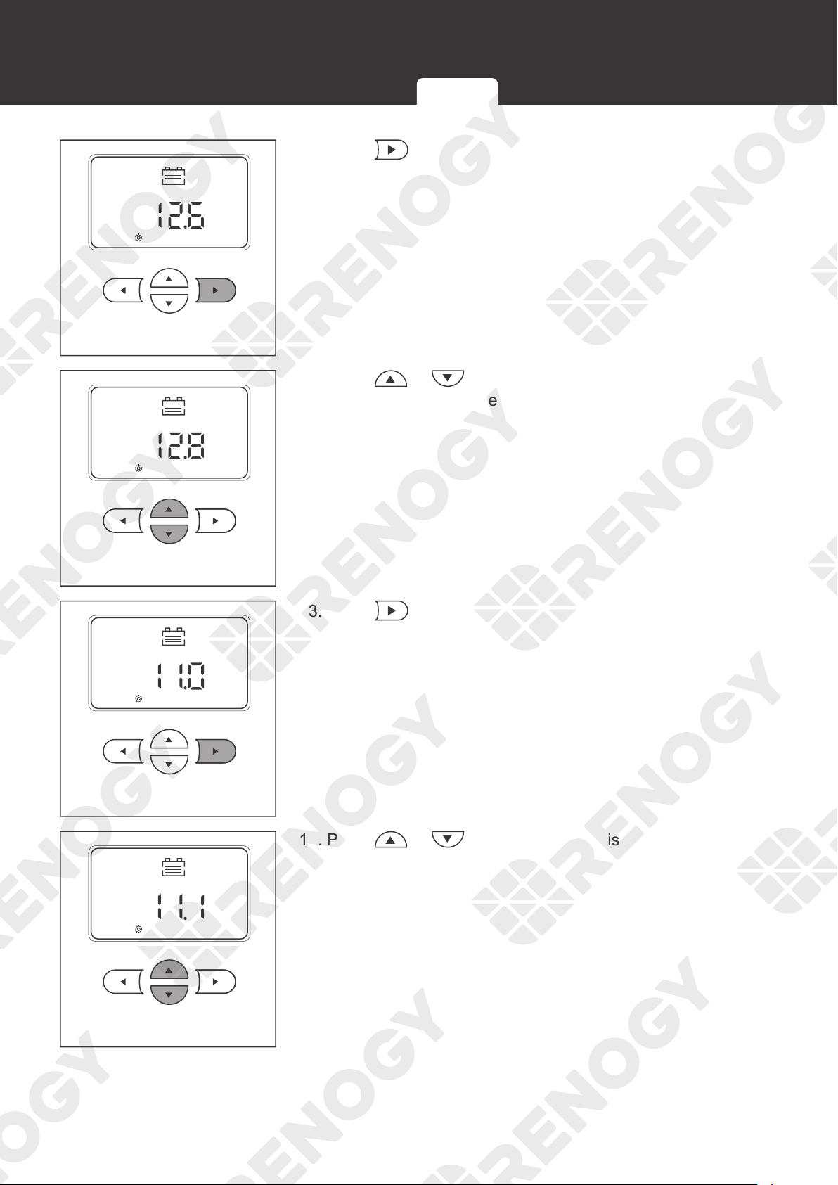
1. In lithium battery mode, the charge controller automatically enables the activation function
and provides a constant voltage of over 13.2V to activate the lithium battery.
2. After the charge controller activates the lithium battery with a constant voltage of 13.2V for
10s, the charge controller will pause for 5s and detect the battery voltage.
If the battery voltage is greater or equal to 11V, the charge controller will exit the lithium
battery activation mode.
If the battery voltage is less than 11V, the charge controller will continue to activate the
lithium battery.
MPPT Technology Four Charging Stages Lithium Battery Activation
08
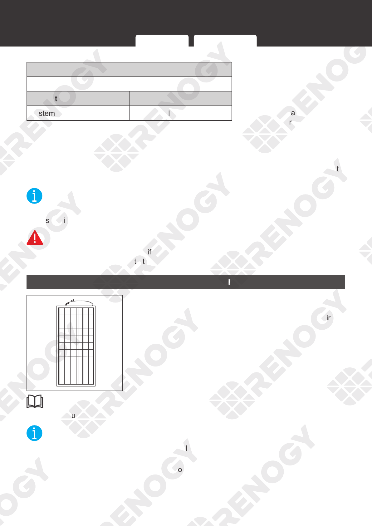
Package Contents
Package Contents
Rover Li Series MPPT Solar
Charge Controller × 1
User Manual × 1
VERSION A6
MPPT Solar Charge Controller
Rover Li Series
12V/24V 20A/30A/40A
USER MANUAL
Renogy Temperature Sensor × 1
(Model: RTSCC)
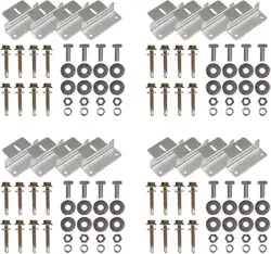
Mounting Bracket × 4
Mounting Bracket Screws × 4
09
Optional Accessories
Optional Accessories
NOT
E
z
You can buy the following optional accessories from renogy.com.
Battery Fuse
RNG-CTRL-RVR20: 25A to 30A
RNG-CTRL-RVR30: 30A to 40A
RNG-CTRL-RVR40: 40A to 50A
The battery fuse protects the charge controller, cables and
batteries from overcurrent.
Solar Panel Fuse
Solar panel fuse provides single circuit protection for solar
panels, preventing damage caused by high currents.
Fuse Cable
The cable is integrated with copper rings at both ends, enabling
the charge controller to be connected with an external fuse.
Bluetooth Module
LINK
POWER
1
Renogy BT-1 Bluetooth Module (sold separately)
Pair the Bluetooth Module with Renogy DC Home app to
monitor and change parameters through a smartphone or tablet.
Download the app by scanning the QR Code on the last page of
the user manual.
10
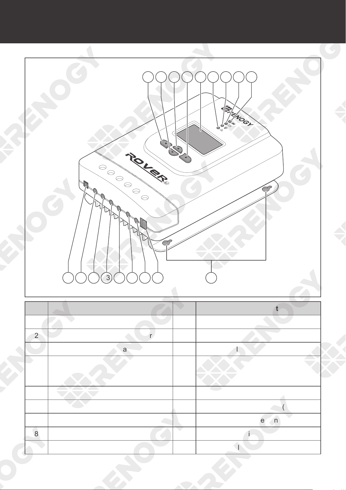
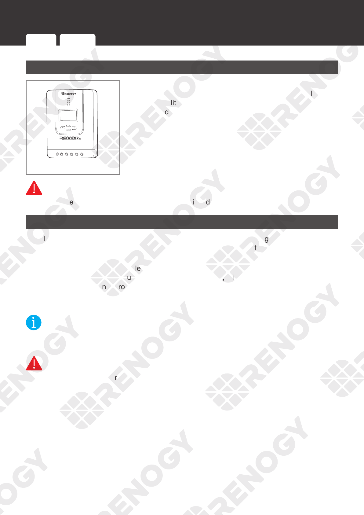
Product Overview
Product Overview
PV+
PV-
BAT+
LOAD+
LOAD-
RS232
BAT-
Temp.
1 6 7 8 92 3 4 5
10 11 12 13 14 15 16 17 18
No. Part & Description No. Part & Description
1 Return to the Previous Menu 10 Temperature Sensor Port
2 Page Down / Decrease Parameter Value 11 Positive Solar Terminal (PV+)
3 Page Up / Increase Parameter Value 12 Negative Solar Terminal (PV-)
4
Enter Sub Menu / Save Parameter
Value / Turn Load On or Off in Manual
Mode
13 Positive Battery Terminal (BAT+)
5 LCD 14 Negative Battery Terminal (BAT-)
6 System Error LED Indicator 15 Positive DC Load Terminal (LOAD+)
7 Load LED Indicator 16 Negative DC Load Terminal (LOAD-)
8 Battery LED Indicator 17 RS232 Port (optional)
9 Solar LED Indicator 18 Mounting Holes
11
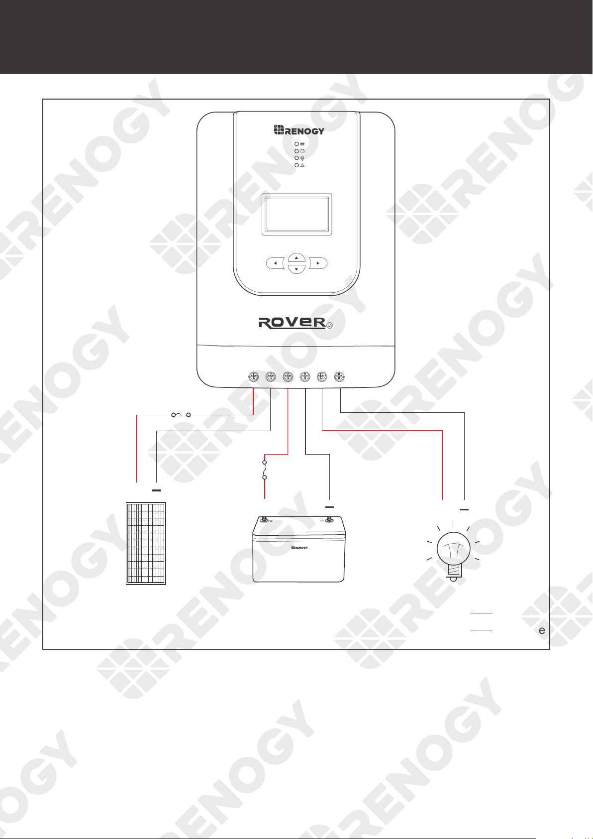
Wiring Diagram
Wiring Diagram
-
+
Negative
Positive
+
Solar Panel
Solar Panel Fuse
Battery Fuse
Battery DC Load
+
+
12
Recommended Cable and Fuse Sizing
Recommended Cable and Fuse Sizing
Recommended Cable Sizing
Model
Rated
Current
Cable
Cable Length
(ft) / (m)
Recommended
Cable Size
Rover Li 12V/24V 20A
MPPT Solar Charge
Controller
(RNG-CTRL-RVR 20)
20A
Solar
(input)
0‒10 ft (0‒3 m) 12 AWG
11‒
20 ft (3‒6 m) 10 AWG
21‒30 ft (6‒9 m) 8 AWG
Battery
(output)
0‒10 ft (0‒3 m) 12 AWG
11‒
20 ft (3‒6 m) 10 AWG
21‒30 ft (6‒9 m) 8 AWG
Rover Li 12V/24V 30A
MPPT Solar Charge
Controller
(RNG-CTRL-RVR 30)
30A
Solar
(input)
0‒10 ft (0‒3 m) 10 AWG
11‒
20 ft (3‒6 m) 8 AWG to 10 AWG
21‒30 ft (6‒9 m) 8 AWG
Battery
(output)
0‒10 ft (0‒3 m) 10 AWG
11‒
20 ft (3‒6 m) 8 AWG to 10 AWG
21‒30 ft (6‒9 m) 8 AWG
Rover Li 12V/24V 40A
MPPT Solar Charge
Controller
(RNG-CTRL-RVR 40)
40A
Solar
(input)
0‒10 ft (0‒3 m) 8 AWG
11‒
20 ft (3‒6 m) 6 AWG to 8 AWG
21‒30 ft (6‒9 m) 6 AWG
Battery
(output)
0‒10 ft (0‒3 m) 8 AWG
11‒
20 ft (3‒6 m) 6 AWG to 8 AWG
21‒30 ft (6‒9 m) 6 AWG
NOT
E
z
The cable specifications listed above account for critical, less than 3% voltage drop and may
not account for all configurations.
z
The size of the fuse cable is consistent with that of the corresponding cable connecting to
the output terminal of the charge controller.
Recommended Cable Sizing Recommended Fuse Sizing
13
Recommended Cable and Fuse Sizing
Recommended Fuse Sizing
For your safety, it is recommended to install fuses at both the input and output ends of the
charge controller to ensure safe operations.
NOT
E
z
Choose appropriate fuses according to the specifications of the solar panel and the charge
controller.
Fuse from Solar Panel to Charge Controller
Max. Current of Solar Panel to Solar Controller Fuse = Total Amps of Solar Panel (Array) * 1.56
Solar Panels in Series Solar Panels in Parallel
Total Amps I: I
1
=I
2
=I
3
Fuse = I
1
* 1.56
Total Amps I: I
1
+I
2
+I
3
Fuse = (I
1
+I
2
+I
3
) * 1.56
NOT
E
z
In the formula, I represents the maximum output current of the solar panel, and 1, 2 or 3
represents the solar panel number, respectively.
INF
O
z
Read the user manual of the solar panel to obtain working voltage parameters, and calculate
the corresponding fuse current according to the formula.
Recommended Cable Sizing Recommended Fuse Sizing
14
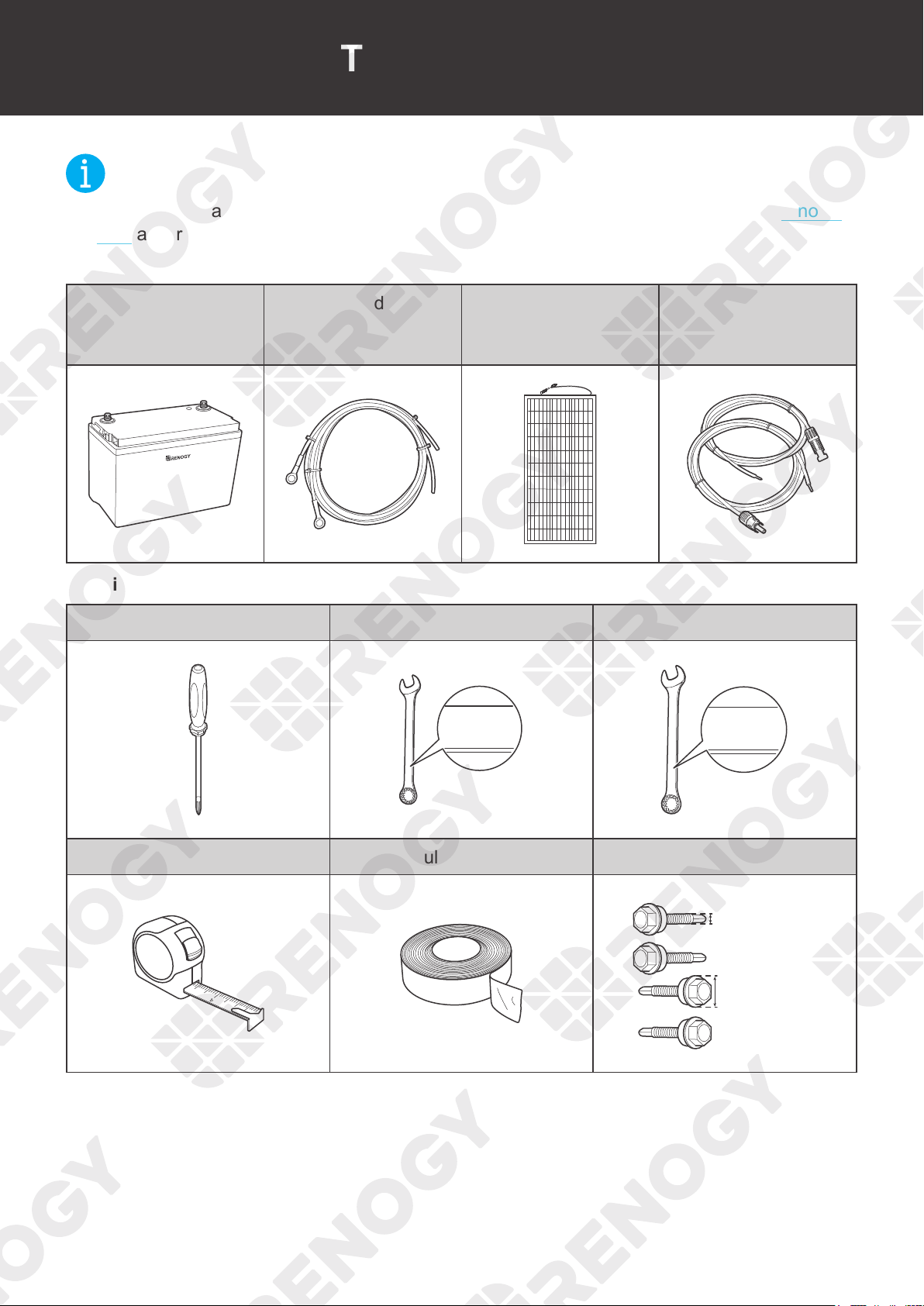
Components & Tools
Components & Tools
NOT
E
z
The adapter cable used in this manual can be made by yourself or purchased from renogy.
com according to the names in Recommended Components.
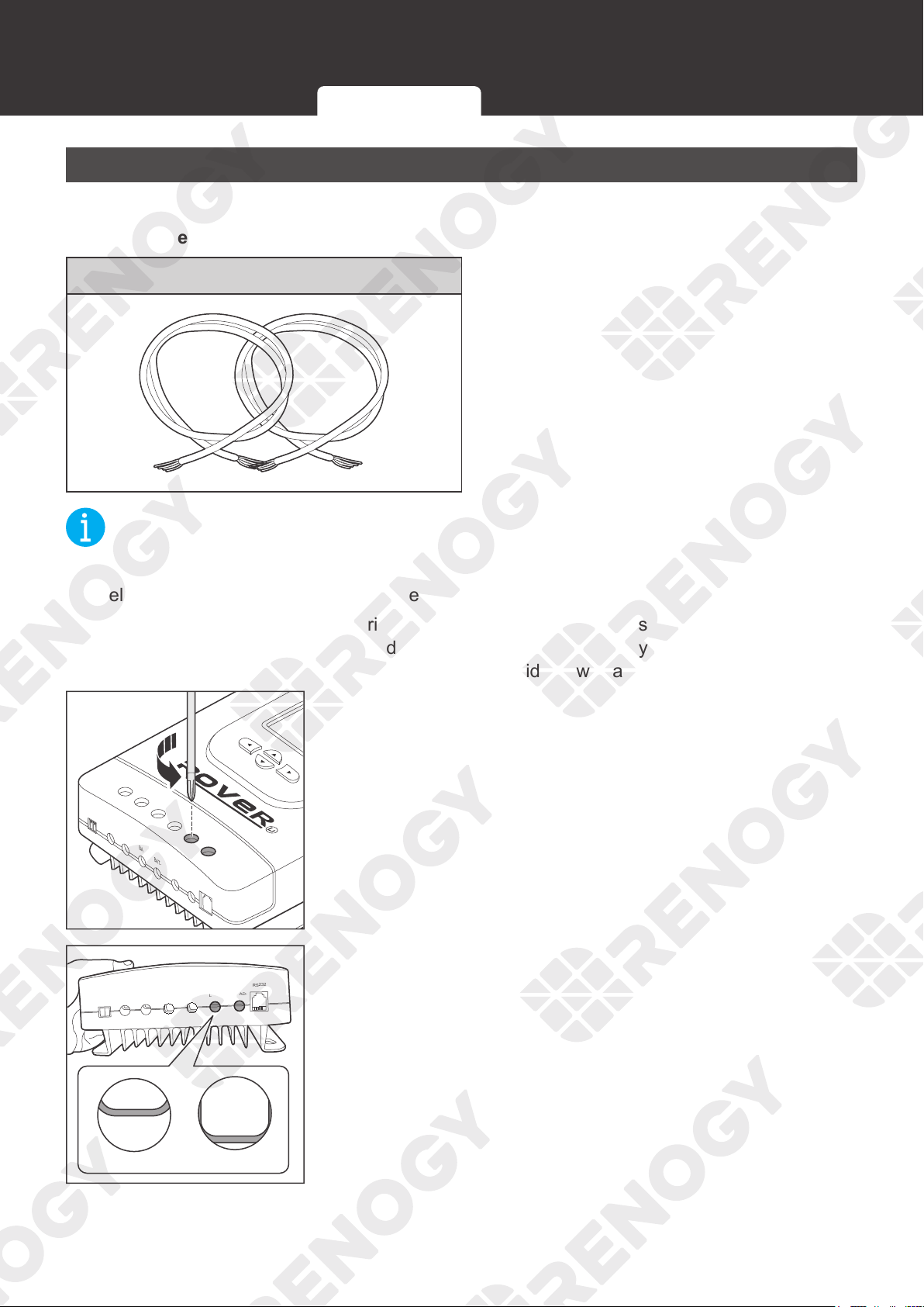
Recommended Components
Battery
Battery Adapter
Cable (Ring Terminal
Adapter Cable)
Solar Panel
Solar Panel Extension
Cables
+
-
Required Tools
Phillips Screwdriver (#2) Wrench (10 mm) Wrench (14 mm)
10mm
10mm
10 mm
14mm
14mm
14 mm
Measuring Tape Insulation Tape Self-tapping Bolts
3
4
5
6
≤5.2 mm
≤0.2 inch
≤4.5 mm
≤0.17 inch
RVR-20:
RVR-30/40:
≤9 mm
≤0.35 inch
≤10 mm
≤0.39 inch
RVR-20:
RVR-30/40:
15
Preparation
Preparation
Inspection
1. Inspect the charge controller for any visible damage
including cracks, dents, deformation, and other visible
abnormalities. All connector contacts shall be clean, dry, and
free of dirt and corrosion.
WARNIN
G
z
Do not use the charge controller if it has any visible damage.
Environment
Install the charge controller indoors and prevent its components from being exposed to direct
sunlight. Prevent water from entering the charge controller. Make sure there is good ventilation.
Make sure that the charge controller is installed with ambient temperature range from
-4°F to
140°F or -20°C to 60°C. To ensure optimal working eciency, it is recommended to keep the
ambient temperature range from -4°F to 113°F or -20°C to 45°C.
Make sure that the charge
controller is installed in an environment with relative humidity between 0% and 95% and no
condensation.
NOT
E
z
Install the charge controller as close to the battery as possible to avoid voltage drops due to
long cables.
WARNIN
G
z
Risk of explosion! Never install the charge controller in a sealed enclosure with flooded
batteries!
Inspection Environment Placement Checking Battery Checking Solar Panel
16
Preparation
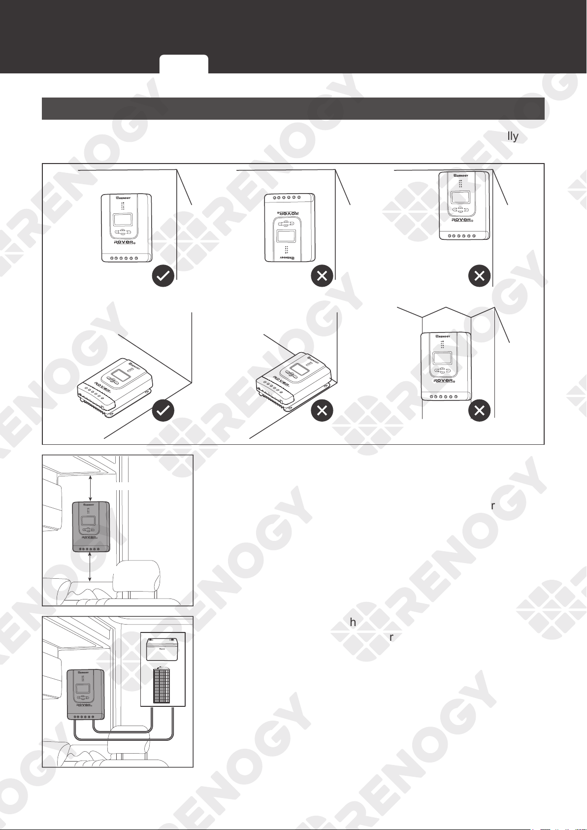
Placement
The charge controller can be fixed vertically (terminals facing down) to a wall or horizontally to
the floor.
PV+
PV-
BAT+
LOAD+
LOAD-
RS232
BAT-
Temp.
PV+
PV-
BAT+
LOAD+
LOAD-
RS232
BAT-
Temp.
≥ 6 in / 150 mm
≥ 6 in / 150 mm
1. Ensure that there is enough space to install the cable. The
charge controller requires at least 6 inches (150 mm) of
clearance above and below for proper air flow. Ventilation is
highly recommended if it is mounted in an enclosure.
-
+
2. Measure the length of the cables connecting to the battery
and the solar panel to make sure that they can be connected
to the charge controller.
Inspection Environment Placement Checking Battery Checking Solar Panel
17
Preparation
NOT
E
z
If the Battery Adapter Cable or Solar Panel Extension Cable is not long enough, you can use
more extension cables or reselect the installation site.
z
Read the
Recommended Cable and Fuse Sizing in this manual, and select appropriate
cables according to the usage.
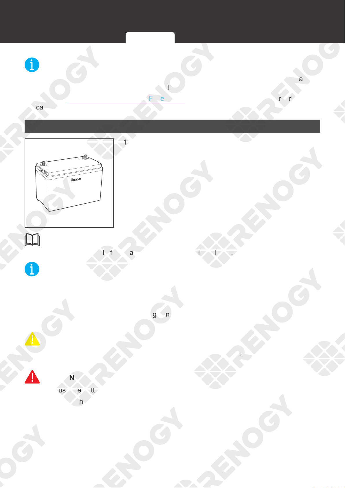
Checking Battery
+
-
1. Inspect the battery for any visible damage including cracks,
dents, deformation, and other visible abnormalities. All
connector contacts shall be clean, dry, and free of dirt and
corrosion.
INFO
z
Read the user manual of the battery carefully before installation.
NOT
E
z
Make sure the battery is working normally.
z
The charge controller can only be applied to deep-cycle gel, flooded, SLD, AGM and Li
batteries.
z
Be sure to wear protective goggles. If getting electrolyte in your eyes, flush your eyes with
clean water immediately.
CAUTIO
N
z
Do not dispose of batteries as household waste. Comply with local, state, and federal laws
and regulations and use recycling channels as required.
WARNIN
G
z
Do not use the battery if it has any visible damage.
z
Do not touch the exposed electrolyte or powder if the battery housing is damaged.
z
The battery may produce explosive gases when being charged. Make sure there is good
ventilation.
Inspection Environment Placement Checking Battery Checking Solar Panel
18
Preparation
System Voltage
Battery or Battery Pack System Voltage = System Voltage U
Batteries in Series Batteries in Parallel
System Voltage U: U
1
+U
2
+U
3
System Voltage U: U
1
=U
2
=U
3
2. Combine the batteries
in parallel or series as
needed. This charge
controller supports a
maximum system voltage
of 32V. Read the user
manual for battery voltage
parameters, and calculate
the voltage of the battery
or battery pack system
according to the formula
to ensure that it does not
exceed 32V.
NOT
E
z
In the formula, U represents the battery voltage, and 1, 2 or 3 represents the battery number
respectively.
WARNIN
G
z
Do not use the charge controller if the battery or battery pack system voltage exceeds 32V.
Doing so will cause damage to the charge controller.
Checking Solar Panel
1. Inspect the solar panel for any visible damage including
cracks, dents, deformation, and other visible abnormalities.
All connector contacts shall be clean, dry, and free of dirt
and corrosion.
INFO
z
Read the user manual of the solar panel carefully before installation.
NOT
E
z
The solar panels can be combined in parallel or in series as needed.
z
Identify the polarities (positive and negative) on the cables used for solar panels. A
reverse
polarity contact may damage the charge controller.
Inspection Environment Placement Checking Battery Checking Solar Panel
19
Preparation
WARNIN
G
z
Do not use the solar panel if it has any visible damage.
Maximum Output Power
Maximum Output Power of Solar Panel or Solar Panel Array
= Maximum Solar Input Power W
Solar Panels in Series Solar Panels in Parallel
Maximum Output Power W:
W
1
+W
2
+W
3
Maximum Output Power W:
W
1
+W
2
+W
3
2. Read the user manual
of the solar panel, and
calculate the maximum
output power of the solar
panel or the solar panel
array according to the
formula.
NOT
E
z
In the formula, W represents the maximum output power of the solar panel, and 1, 2 or 3
represents the solar panel number, respectively.
Model RNG-CTRL-RVR 20 RNG-CTRL-RVR 30 RNG-CTRL-RVR 40
Rated Solar Input
Power
12V @ ≤ 260W 12V @ ≤ 400W 12V @ ≤ 520W
24V @ ≤ 520W 24V @ ≤ 800W 24V @ ≤ 1040W
Working Voltage
Working Voltage of Solar Panel or Solar Panel Array =
Working voltage U
Solar Panels in Series Solar Panels in Parallel
Working Voltage U: U
1
+U
2
+U
3
Working Voltage U: U
1
=U
2
=U
3
3. Read the user manual
of the solar panel, and
calculate the working
voltage of the solar panel
or the solar panel array
according to the formula.
NOT
E
z
In the formula, U represents the working voltage of the solar panel, and 1, 2 or 3 represents
the solar panel number, respectively.
WARNIN
G
z
Ensure that the working voltage of the solar panel or the solar panel array does not exceed
100V.
Inspection Environment Placement Checking Battery Checking Solar Panel
20
Mounting
Mounting
The charge controller can be mounted on a vertical surface with mounting holes or provided
brackets.
NOT
E
z
Make sure that the charge controller is installed firmly to prevent it from falling off.
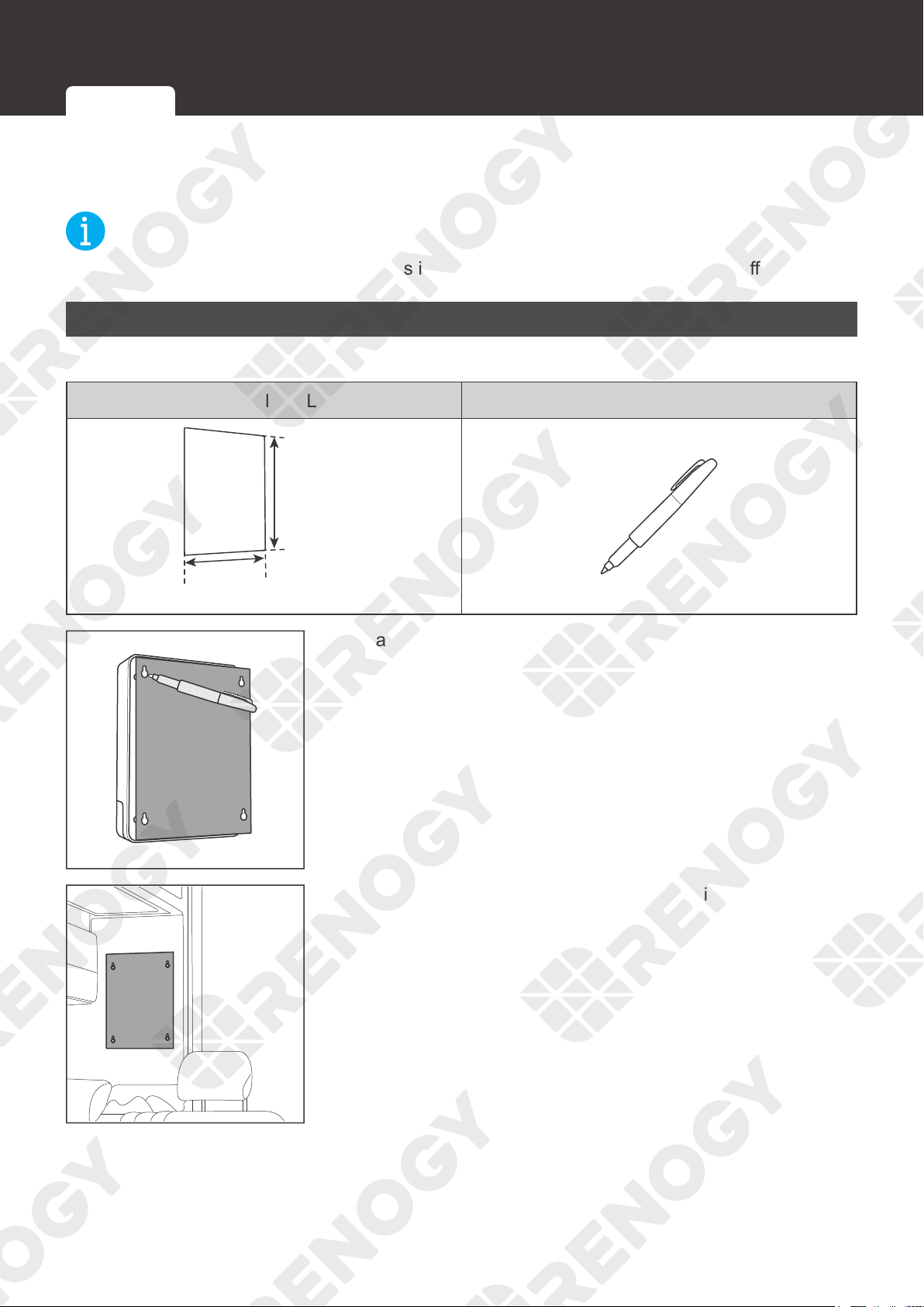
Wall-mounted
Required Tools
Installation Template (Letter Size) Marker Pen
≥238 mm
≥9.38 in
≥172 mm
≥6.78 in
1. Mark the four mounting holes on a piece of paper.
2. Tape the paper to the desired location for installation.
Wall-mounted Mounting with Brackets
21
Mounting
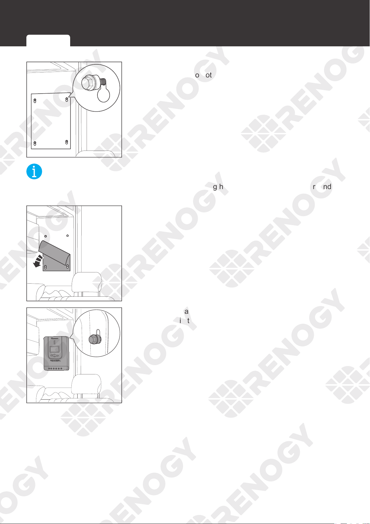
3. Install the screws according to the mounting holes marked
on the paper. Do not overtighten the bolt.
NOT
E
z
Choose appropriate screws according to the mounting holes of the charge controller, and
leave some gap between the screw and the surface.
4. Tear off the paper.
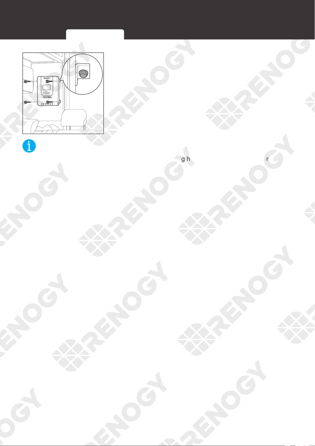
5. Hang the charge controller onto the wall and verify all screw
heads are in the mounting holes.
Wall-mounted Mounting with Brackets
22
Mounting
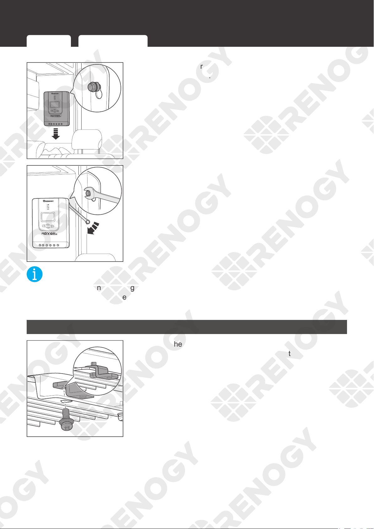
6. Release the charge controller and slide it down into place.
Tighten the screws.
7. If the screws are not secure, tighten them clockwise with a
suitable wrench.
NOT
E
z
If the gap between the charge controller and the mounting surface is too large and the
screws cannot be tightened with a wrench, remove the charge controller and adjust the
screws. Ensure that there is no gap between the charge controller and the surface.
Mounting with Brackets
1. Secure the Mounting Brackets on the mounting holes of the
charge controller with the Mounting Bracket Screws.
Wall-mounted Mounting with Brackets
23
Mounting
2. Place the charge controller against a flat surface and secure
it with screws.
NOT
E
z
Choose appropriate screws according to the mounting holes of the charge controller.
Wall-mounted Mounting with Brackets
24
Installation
Installation
Battery Wiring
PV+
PV-
BAT+
LOAD+
LOAD-
RS232
BAT-
Temp.
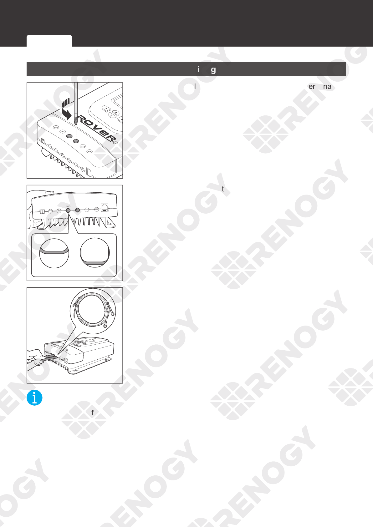
1. Rotate the cable retainer of the BAT
-, and BAT+ t
erminals
counterclockwise with a screwdriver.
Temp.
PV+
PV-
BAT+
BAT-
LOAD+
LOAD-
RS232
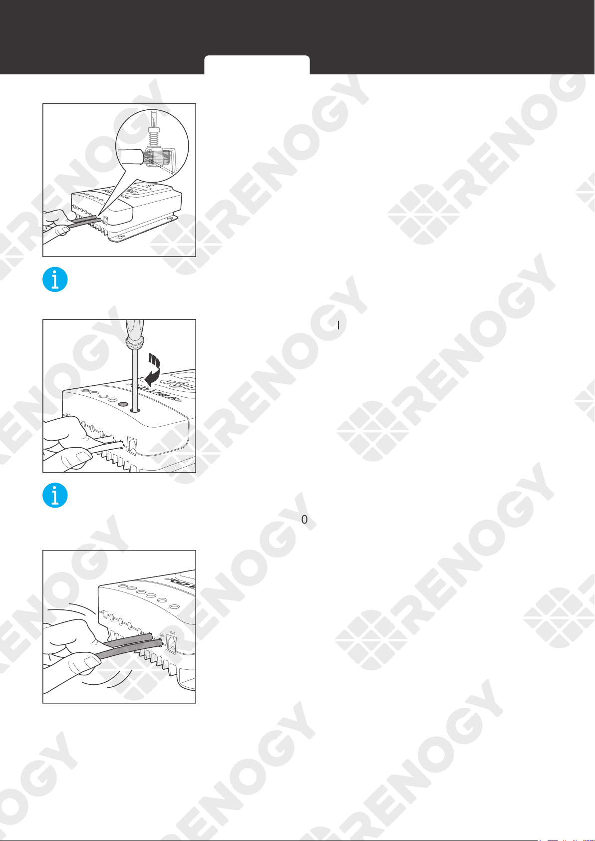
OpenClose
2. Make sure the cable retainer is completely open.
PV+
PV-
BAT+
LOAD+
LOAD-
RS232
BAT-
Temp.
3. Insert the bare ends of the Battery Adapter Cables into the
corresponding
BAT+
and
BAT-
.
NOT
E
z
Strip off some of the protective sheath of cables and insert the bare ends of the cables into
the screw terminals.
Battery Wiring
Solar Wiring
Load Wiring (Optional)
25
Installation
PV+
PV-
BAT+
LOAD+
LOAD-
RS232
BAT-
Temp.
PV+
PV-
BAT+
LOAD+
LOAD-
RS232
BAT-
Temp.
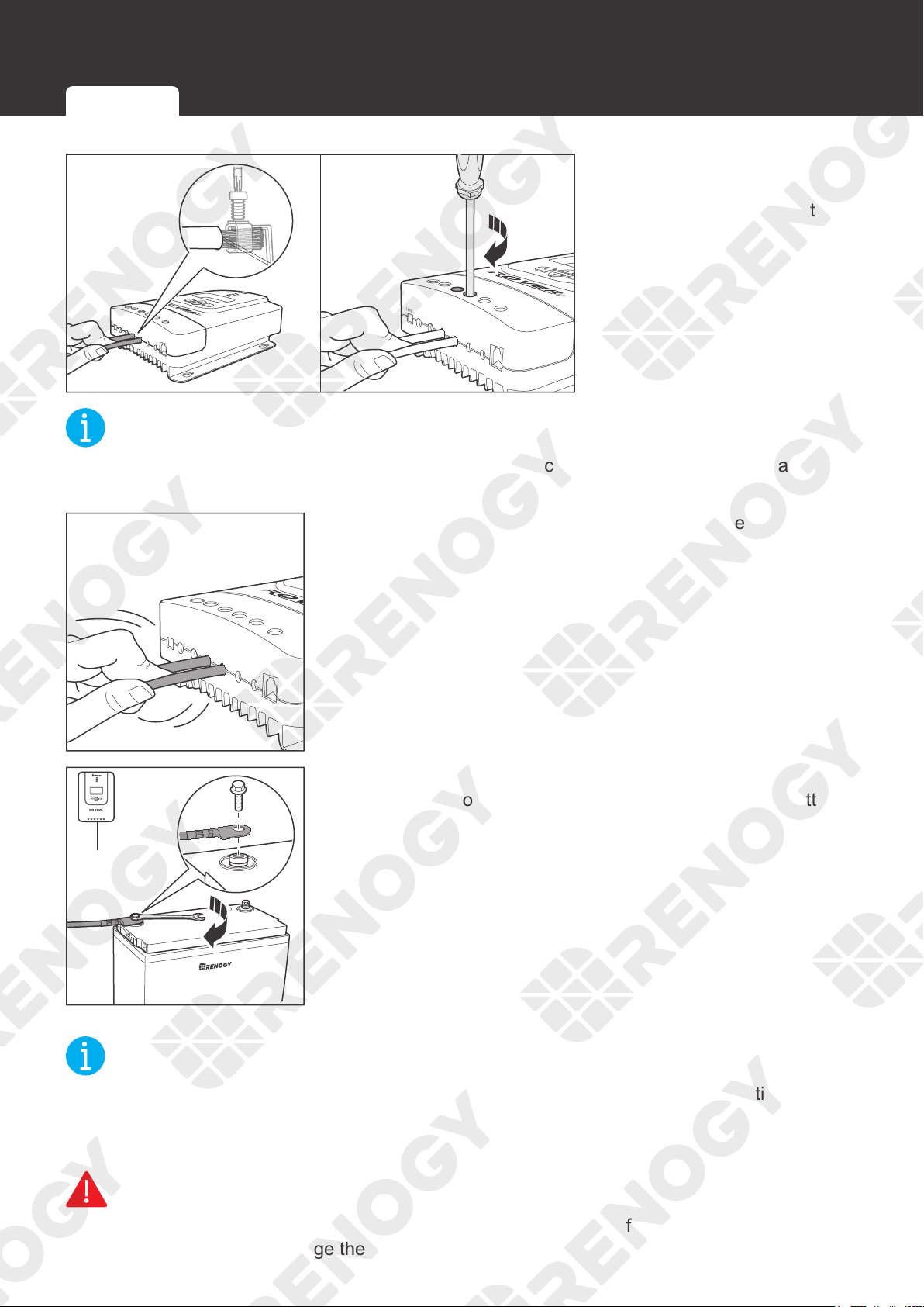
4. Rotate the screws
clockwise to clamp the
wire down and close the
cable retainer.
NOT
E
z
The torque of the cable retainer is 1.2 N·m (10.53 lb-inch). Do not overtighten the cable
retainer screws. Otherwise it will lead to stripped screws or screw bending.
PV+
PV-
BAT+
LOAD+
LOAD-
RS232
BAT-
Temp.
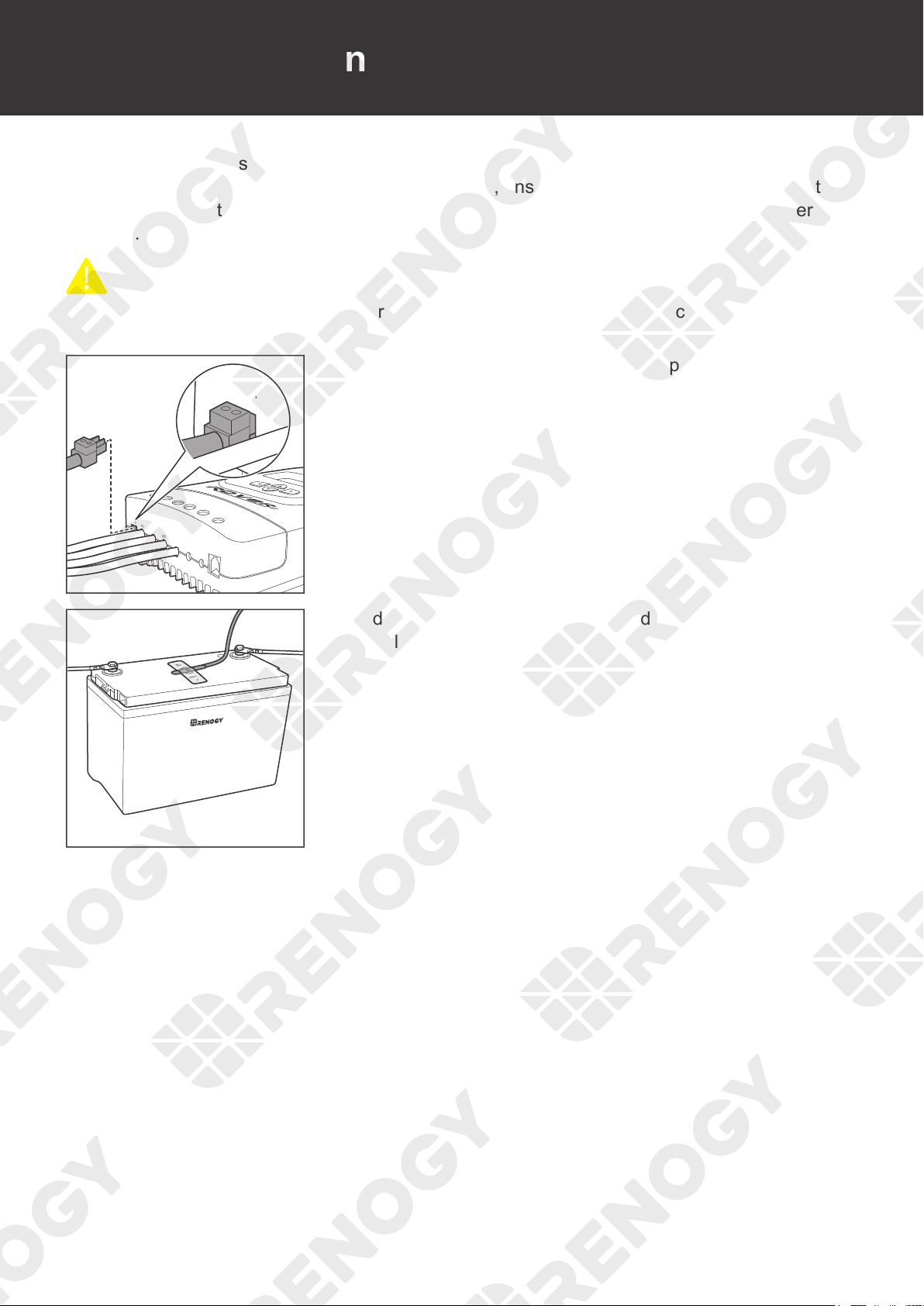
5. Make sure all connections are tight and secure.
BAT-
+
-
1
2
12
-
6. Attach the Battery Adapter Cable connecting to the
BAT
- of
the charge controller to the negative terminal of the battery,
and tighten the bolt with a wrench.
NOT
E
z
Select a suitable wrench according to the specifications of the positive and negative wire
fixing bolts of the battery.
z
Make sure all connections are tight and secure.
WARNIN
G
z
Identify the polarities (positive and negative) on the cables used for the batteries. A reverse
polarity contact may damage the charge controller.
Battery Wiring
Solar Wiring Load Wiring (Optional)
26
Installation
BAT+
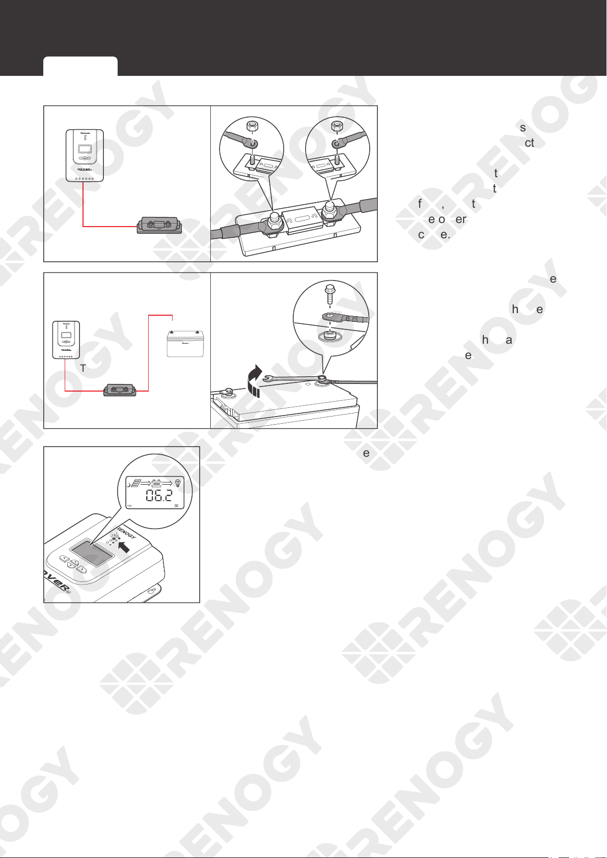
7. For your safety, it is
recommended to use a
battery fuse. Connect the
Battery Adapter Cable
connecting to the
BAT+
to one end of the battery
fuse, and then connect
the other end to the fuse
cable.
+
-
+
+
BAT+
8. Attach the Battery Adapter
Cable connecting to
the
BAT+
of the charge
controller
to the
positive
terminal of the battery,
and tighten the bolt with a
wrench.
9. Once the tray cables are connected to the battery, the LCD
and the Battery LED Indicator will light up, and the charge
controller enters nighttime mode.
Battery Wiring
Solar Wiring Load Wiring (Optional)
27
Installation
Solar Wiring
PV+
PV-
BAT+
LOAD+
LOAD-
RS232
BAT-
Temp.
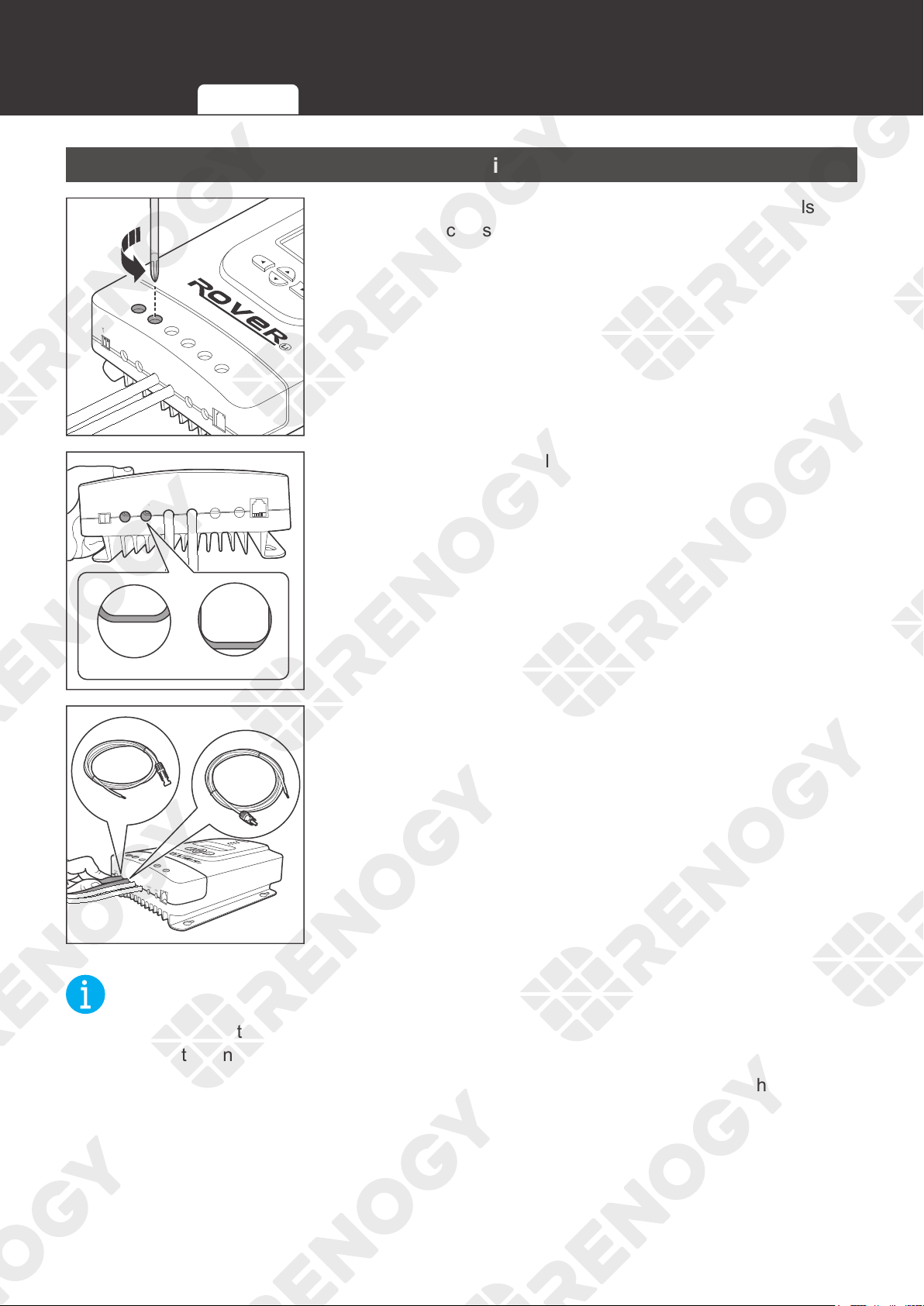
1. Rotate the cable retainer of the PV
-, and
PV
+ t
erminals
counterclockwise with a screwdriver.
Temp.
PV+
PV-
BAT+
BAT-
LOAD+
LOAD-
RS232
OpenClose
2. Make sure the terminal hatch is completely open.
PV+
PV-
BAT+
LOAD+
LOAD-
RS232
BAT-
Temp.
3. Insert the bare ends of the Solar Panel Extension Cables
into the corresponding PV
+
and PV
-
.
NOT
E
z
Strip off some of the protective sheath of cables and insert the bare ends of the cables into
the screw terminals.
z
Connect the male connector of the Solar Panel Extension Cable to the PV- and the female
connector to the PV+.
Battery Wiring
Solar Wiring
Load Wiring (Optional)
28
Installation
PV+
PV-
BAT+
LOAD+
LOAD-
RS232
BAT-
Temp.
PV+
PV-
BAT+
LOAD+
LOAD-
RS232
BAT-
Temp.
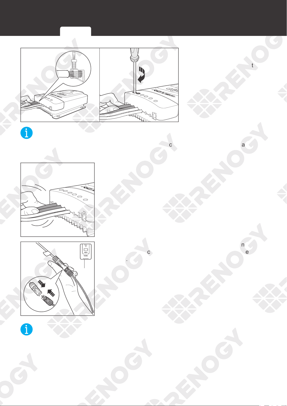
4. Rotate the screws
clockwise to clamp the
wire down and close the
cable retainer.
NOT
E
z
The torque of the cable retainer is 1.2 N·m (10.53 lb-inch). Do not overtighten the cable
retainer screws. Otherwise it will lead to stripped screws or screw bending.
PV+
PV-
BAT+
LOAD+
LOAD-
RS232
BAT-
Temp.
5. Make sure all connections are tight and secure.
-
PV-
6. Connect the Solar Panel Extension Cable connecting to PV-
of the charge controller to the negative terminal of the solar
panel.
NOT
E
z
Make sure all connections are tight and secure.
Battery Wiring
Solar Wiring Load Wiring (Optional)
29
Installation
+
+
PV+
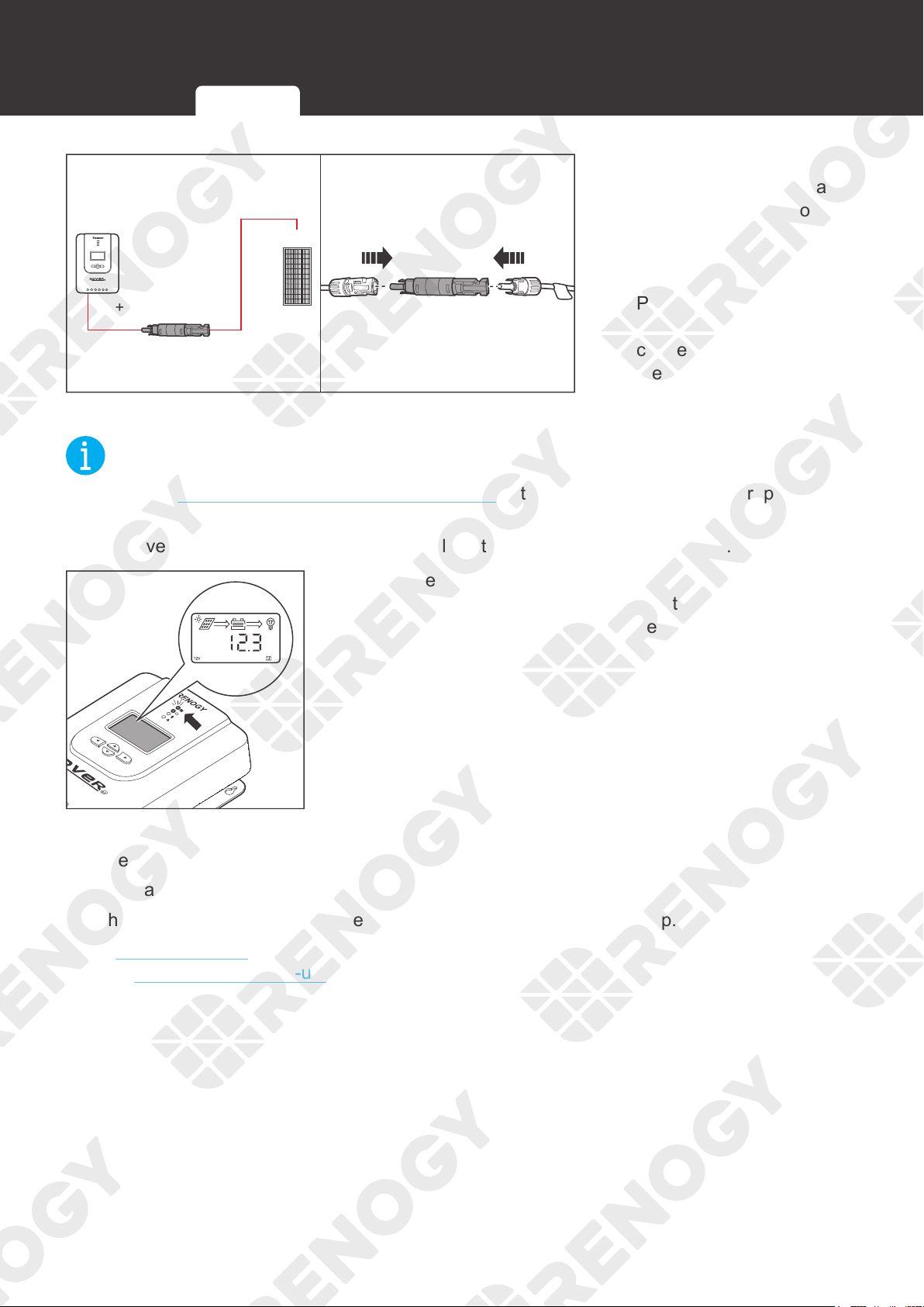
7. For your safety, it is
recommended to use a
battery fuse and a solar
panel fuse. Connect the
Solar Panel Extension
Cable connecting to the
PV+
to one end of the
solar panel fuse, and then
connect the other end of
the fuse to the positive
terminal of the solar panel.
NOT
E
z
Read the
Recommended Cable and Fuse Sizing in this manual, and select appropriate solar
panel fuses according to the usage.
z
Remove the cover of the solar panels or place them face up after connection.
8. Once the Solar Panel Extension Cables are connected to
the solar panels, the Solar LED Indicator will light up, and
the charge controller enters daytime mode.
The charge controller needs troubleshooting if any of the following errors occur:
z
The LCD does not light up.
z
The battery voltage is not displayed on the LCD.
z
The Battery LED Indicator or the Solar LED Indicator does not light up.
Read
Troubleshooting in the user manual. For more instructions, contact our customer service
through renogy.com/contact-us/.
Battery Wiring
Solar Wiringr Load Wiring (Optional)
30
Installation
Load Wiring (Optional)
You can choose to connect the charge controller to a DC load (≤20A) on demand.
Recommended Accessories
Bare Wire
NOT
E
z
DC load operating current needs to be less than or equal to 20A.
z
Select appropriate cables based on the DC load operating current.
z
The DC load is powered by batteries, so ensure that the DC load is compatible with
the battery voltage. If a 12V DC load is installed in a 24V battery system, the incorrect
connection will damage the charge controller and void the warranty.
PV+
PV-
BAT+
LOAD+
LOAD-
RS232
BAT-
Temp.
1. Rotate the cable retainer of the LOAD
-, and
LOAD
+
t
erminals counterclockwise with a screwdriver.
Temp.
PV+
PV-
BAT+
BAT-
LOAD+
LOAD-
RS232
OpenClose
2. Make sure the cable retainer is completely open.
Battery Wiring
Solar Wiring
Load Wiring (Optional)
31
Installation
PV+
PV-
BAT+
LOAD+
LOAD-
RS232
BAT-
Temp.
3. Insert the bare ends of the cables into both LOAD- and
LOAD
+
terminals.
NOT
E
z
Strip some insulation off bare wires according to the depth of the installation hole.
PV+
PV-
BAT+
LOAD+
LOAD-
RS232
BAT-
Temp.
4. Rotate the screws clockwise to clamp the wire down and
close the cable retainer.
NOT
E
z
The torque of the cable retainer is 1.2 N·m (10.53 lb-inch). Do not overtighten the cable
retainer screws. Otherwise it will lead to stripped screws or screw bending.
PV+
PV-
BAT+
LOAD+
LOAD-
RS232
BAT-
Temp.
5. Make sure all connections are tight and secure.
Battery Wiring
Solar Wiring
Load Wiring (Optional)
32
Installation
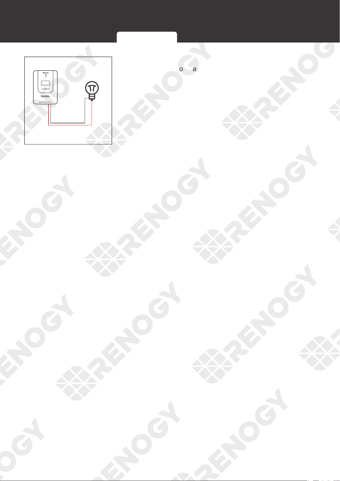
LOAD-LOAD+
+
DC Load
-
6. Connect the cable at the LOAD- terminal to the negative
terminal of the load and connect the cable at t
he
LOAD
+
terminal to the positive terminal of the load.
Battery Wiring
Solar Wiring
Load Wiring (Optional)
33
Temperature Sensor
Temperature Sensor
The temperature sensor can detect the temperature of the battery and send the temperature to
the charge controller for charging voltage calibration, ensuring that the charge controller (with
operating temperature ranging fro
m -35°C to 45°C or -31°F to 113°F
) can charge the battery
normally.
CAUTIO
N
z
Do not use the temperature sensor on a LiFePO4 (LFP) battery which comes with a battery
management system (BMS).
PV+
PV-
BAT+
LOAD+
LOAD-
RS232
BAT-
Temp.
Temp.
1. Insert the green connector of the Temperature Sensor to the
Temperature Sensor Port of the charge controller.
+
-
2. Adhere the sensor on the top or side of the battery with the
insulation tape.
34
Bluetooth Module (Optional)
Bluetooth Module (Optional)
With a Renogy BT-1 Bluetooth Module, the charge controller can be connected to the DC
Home app for remote device monitoring. You can monitor and modify parameters of the charge
controller through the DC Home app.
INF
O
z
Read the user manual of the Renogy BT-1 Bluetooth Module carefully before connection.
NOT
E
z
Make sure that the charge controller is turned on before the connection.
z
Scan the QR code on the last page of the uesr manual to download the DC Home app.
PV+
PV-
BAT+
LOAD+
LOAD-
RS232
BAT-
Temp.
Load
LOAD-
RS232
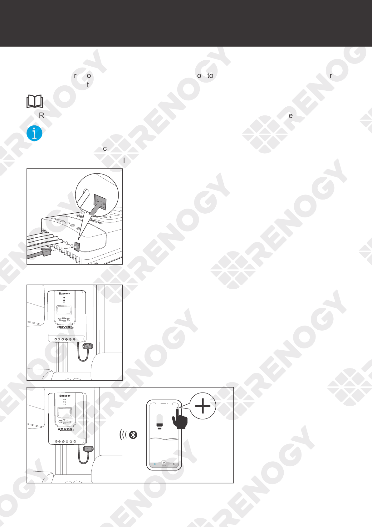
1. Connect the Bluetooth Module to the RS232 port on the
charge controller.
1
2. Place the Bluetooth module in a suitable site.
My Renogy
25%
Device
No device yet...
Community Personal
1
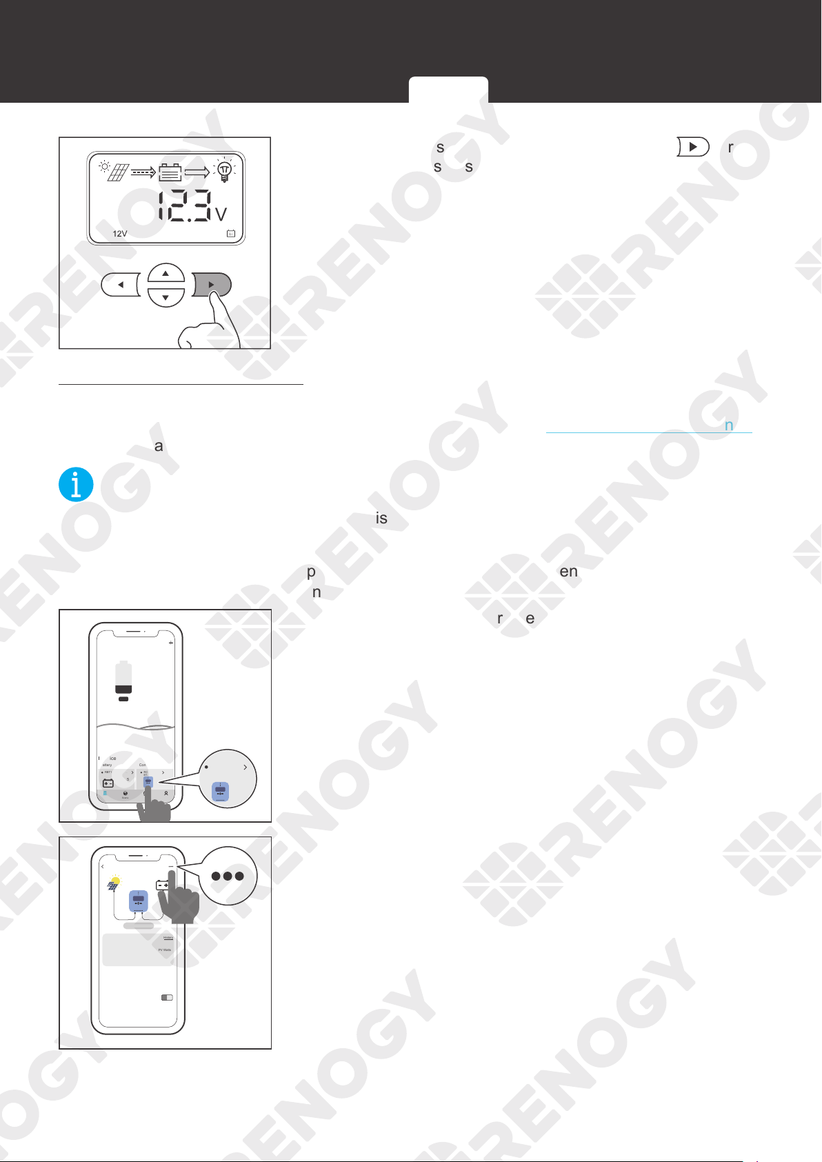
3. Open the DC Home app.
Tap + to search for new
devices.
35
Bluetooth Module (Optional)
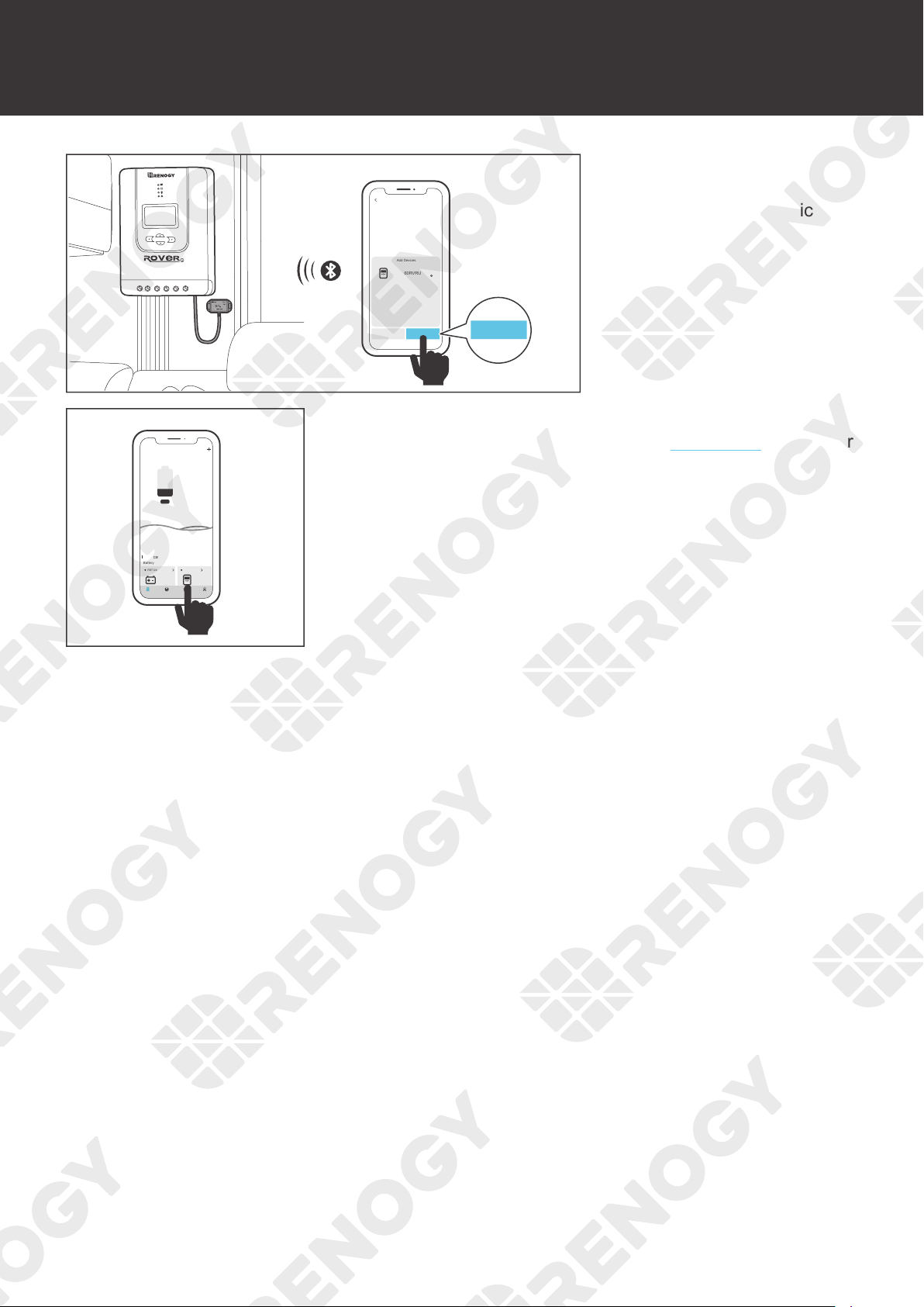
1
HUB Mode
Add Devices
RCC60RVRU
Cancel Confirm
Confirm
4. Tap Confirm to add
the newly found charge
controller to the device list.
My Renogy
25%
A
Device
Device
Battery
RBT12400LFPL-...
Controller
Scene Community Me
RCC60RVRU
%
25
A
0 0
W
0
5. Tap the charge controller to check paraneters of the charge
controller. To modify parameters, see User Mode in the user
manual.
36
Battery Type
Battery Type
Setting the Battery Type
Set the battery type immediately after installing the charge controller. If the charge controller has
been connected to a Renogy BT-1 Bluetooth Module, you can also set the battery type from the
DC Home app. For more details, see User Mode in this manual.
WARNIN
G
z
Refer to technical specifications of the battery provided by the manufacturer when choosing
a preset battery. Incorrect battery type selection resulting in damage will not be covered by
warranty.
NOT
E
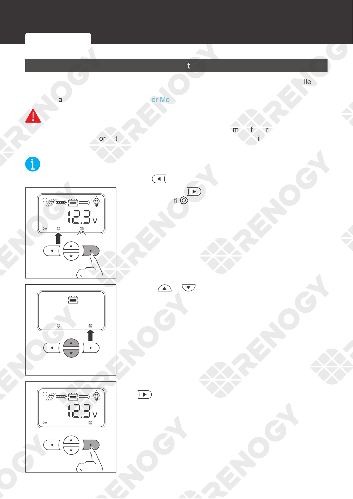
z
To cancel the setting and exit, press
.
3s
1. Press and hold on the charge controller for about 3
seconds unti
is lit up and the battery type icon starts
flashing.
2. Press or to select the desired battery type.
3s
3. After the battery type has been selected, press and hold
for about 3 seconds to save the settings.
Setting the Battery Type Battery Charging Parameters User Mode
37
Battery Type
Battery Charging Parameters
If your battery is not compatible with the preset charging configuration of the charge controller,
enter the user mode to program battery parameters. If the charge controller has been connected
to a Renogy BT-1 Bluetooth Module, you can also program battery parameters through the DC
Home app. For more instructions, read the User Mode in this manual.
WARNIN
G
z
Before modifying battery parameters, check the table below first. Incorrect parameter setting
will damage the charge controller and void the warranty.
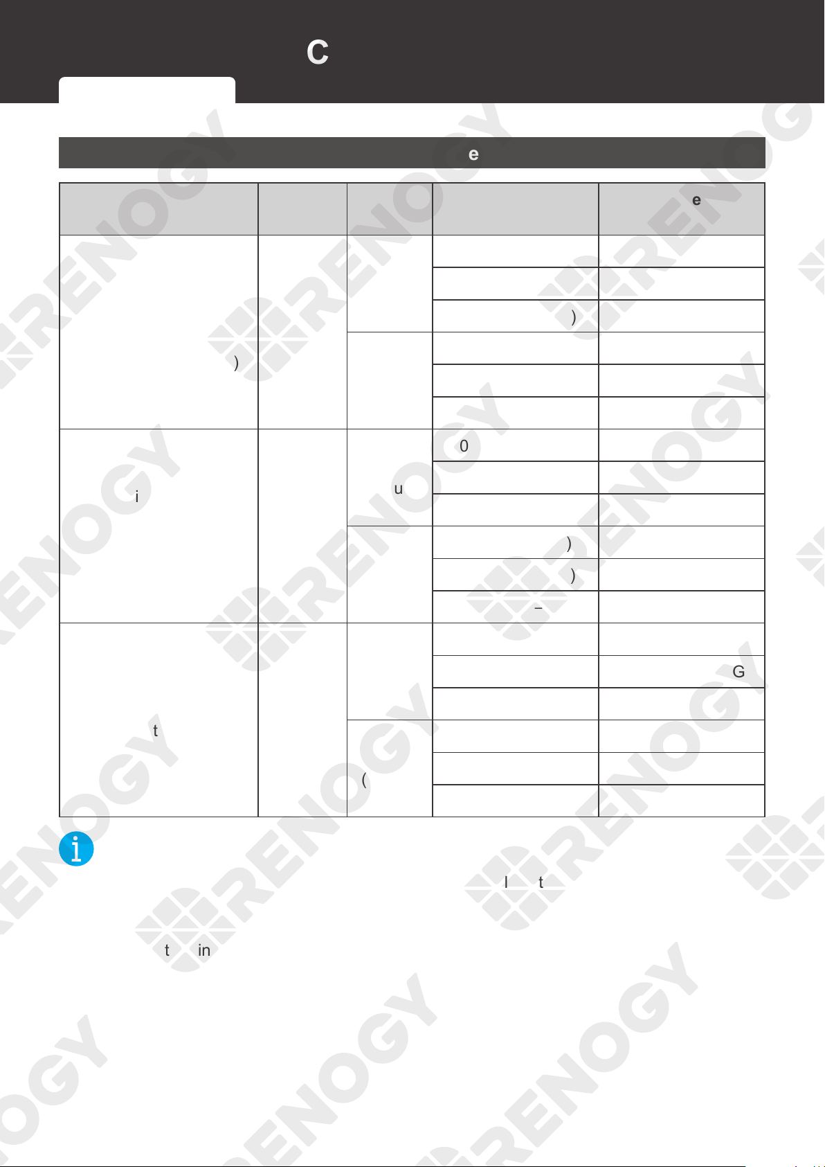
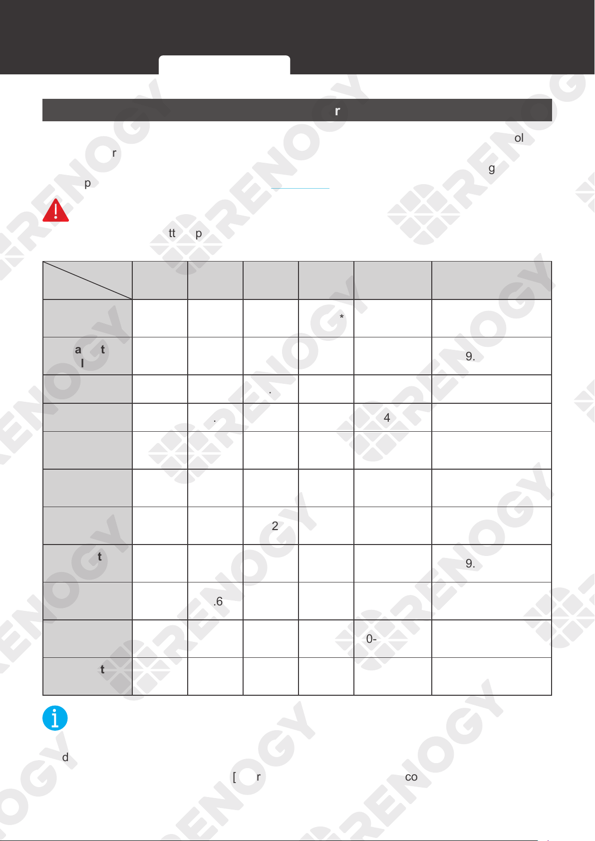
Battery Type
Parameters
AGM /
SLD
Gel Flooded Li (LFP) User Mode
User
Recommended
Overvoltage
Shutdown
16.0V 16.0V 16.0V 16.0V* [16.0V] —
Equalization
Volatge
—14.6V 14.8V —14.4V 9.0-17.0V
Boost Voltage 14.2V 14.4V 14.6V 14.4V* 14.4V 9.0-17.0V
Float Voltage 13.8V 13.8V 13.8V —14.4V 9.0-17.0V
Boost Return
Voltage
13.2V 13.2V 13.2V 13.2V [13.2V] —
Undervoltage
Warning
12.0V 12.0V 12.0V 12.0V [12.0V] —
Undervoltage
Return
12.2V 12.2V 12.2V 12.2V [12.2V] 9.0-17.0V
Low Voltage
Disconnect
11.0V 11.0V 11.0V 11.0V [11.1V] 9.0-17.0V
Low Voltage
Reconnect
12.6V 12.6V 12.6V 12.6V [12.6V] 9.0-17.0V
Equalization
Duration
—2 hours 2 hours —[0-300 min] —
Boost
Duration
2 hours 2 hours 2 hours —0-300 min 10-300 min
NOT
E
z
The parameters listed in the table above apply to 12V batteries. For the 24V batteries,
double the number of the parameters.
z
Parameters in square brackets ([ ]) are automatically adjusted according to the relevant
settings, and cannot be set directly.
Setting the Battery Type Battery Charging Parameters User Mode
38
Battery Type
z
* By default, Boost Voltage and Overvoltage Shutdown values are set to 14.4V and 16.0V
respectively for lithium batteries. Manual modification on Boost Voltage for lithium batteries
may trigger Overvoltage Shutdown alarms. Therefore, the Rover Li charge controller
automatically sets the Overvoltage Shutdown parameter to a value of Boost Voltage plus 2
to ensure normal battery charging.
z
For the default values of User Mode, refer to the DC Home App.
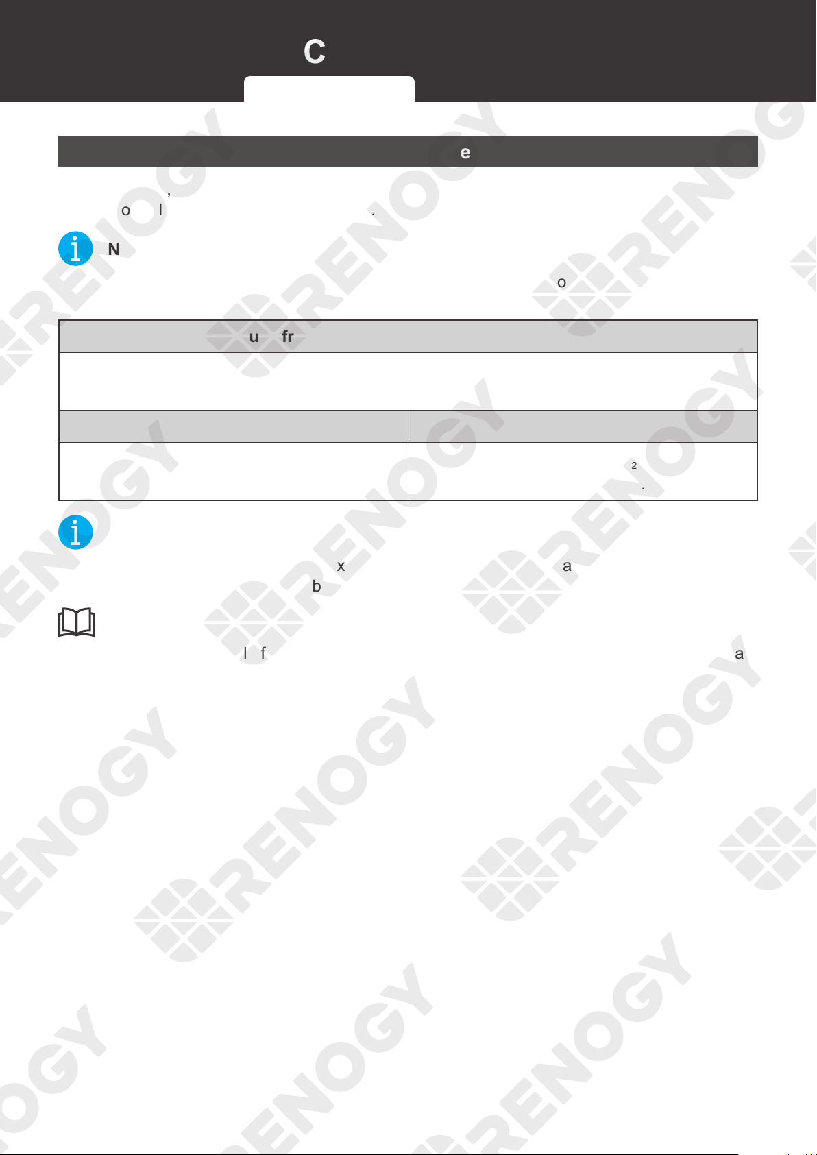
User Mode
WARNIN
G
z
Before modifying battery parameters in user mode, check the table below and consult the
battery manufacturer to check whether modification is allowed. Incorrect parameter setting
will damage the charge controller and void the warranty.
Parameters Description
Model
Rover Li 12V/24V 20A MPPT Solar Charge Controller
(RNG-CTRL-RVR20)
Rover Li 12V/24V 30A MPPT Solar Charge Controller
(RNG-CTRL-RVR30)
Rover Li 12V/24V 40A MPPT Solar Charge Controller
(RNG-CTRL-RVR40)
Overvoltage Shutdown
The default protection voltage is 16V. Improper setting may affect
safe use of the battery. Please consult the battery manufacturer
and check if this voltage value needs to be modified.
Boost Voltage
This value affects whether the battery can be fully charged. Please
consult the battery manufacturer and set the value properly.
Float Voltage
This value affects whether the battery can be fully charged. Please
consult the battery manufacturer and set the value properly.
Equalization Voltage
1. For lead-acid batteries, please consult your battery
manufacturer to obtain the voltage value and then complete the
settings according to the feedback.
2. If no equalization is required, set it to the same voltage as
Boost.
Undervoltage Warning
This voltage value affects the life of the battery. Consult the
battery manufacturer and check if this voltage value needs to be
set.
Low Voltage Shutdown
Low Voltage Reconnect
Setting the Battery Type Battery Charging Parameters User Mode
39
Battery Type
Parameters Description
Boost Duration
Please consult the battery manufacturer if it is necessary to set
these values.
Equalization Duration
Equalization Interval
Setting via the Charge Controller
NOT
E
z
To cancel the setting and exit, press .
3s
1. Press and hold on the charge controller for about 3
seconds until
is lit up and the battery type icon starts
flashing.
2. Press or to select 。
3. Press to set the system voltage.
Setting the Battery Type Battery Charging Parameters User Mode
40
Battery Type
4. Press or to
select 12V or 24V system
voltage according to the
usage.
V
EQUATIZE
5. Press to set the equalization voltage.
V
EQUATIZE
6. Press or to adjust the equalization voltage
according to the usage.
CAUTIO
N
z
Overcharging and excessive gas precipitation may damage the battery plates and activate
material shedding on them. Too high of an equalization charging voltage or too long of
equalization charging may damage the battery. Review the specific requirements of the
battery used in the system carefully.
z
It is recommended to use only non-sealed, vented, flooded, and wet cell lead acid batteries
in the equalization stage.
z
Do not equalize VRLA type AGM, gel, and lithium cell batteries unless permitted by battery
manufacturers.
z
If no equalization is required, set it to the same voltage as Boost.
Setting the Battery Type Battery Charging Parameters User Mode
41
Battery Type
V
BOOST
7. Press to set the boost voltage.
V
BOOST
8. Press or to adjust the boost voltage according to
the usage.
V
FLOAT
9. Press to set the float voltage.
V
FLOAT
10. Press or adjust the float voltage according to the
usage.
Setting the Battery Type Battery Charging Parameters User Mode
42
Battery Type
V
11. Press to set the overdischarge return voltage.
V
12. Press or adjust the overdischarge return voltage
according to the usage.
V
13. Press to set the overdischarge voltage.
V
14. Press or to adjust the overdischarge voltage
according to the usage.
Setting the Battery Type Battery Charging Parameters User Mode
43
Battery Type
3s
15. After the settings are completed, press and hold for
about 3 seconds to save the settings.
Setting via the DC Home app
If the charge controller has been connected to a Renogy BT-1 Bluetooth Module, add the charge
controller to the DC Home app first. For more instructions, see the
Bluetooth Module (Optional)
in the user manual.
NOT
E
z
Make sure the Bluetooth of your phone is turned on.
z
Make sure the Renogy BT-1 Bluetooth Module is powered on.
z
Illustrations of the DC Home app in this user manual are for reference only. Follow the
instructions based on the current app version.
My Renogy
25%
A
Device
Device
Battery
RBT12400LFPL-...
Controller
Scene Community Me
RCC60RVRU
BT-TH-66EA3932
%
25
A
0 0
W
0
RCC60RVRU
BT-TH-66EA3932
1. Tap the charge controller to enter the device details
interface.
PV Screen
0
V 0 A 0 W
0.052 kwh
Solar Volts Solar Amps
Battery Charging Volts
Battery Charging Amps
Battery Type
Sealed 77
o
C
o
F
0 A
13.2 V
Battery Temperature
Total Energy
NOT CHARGING
History
PV Watts
Produced
RCC60RVRU
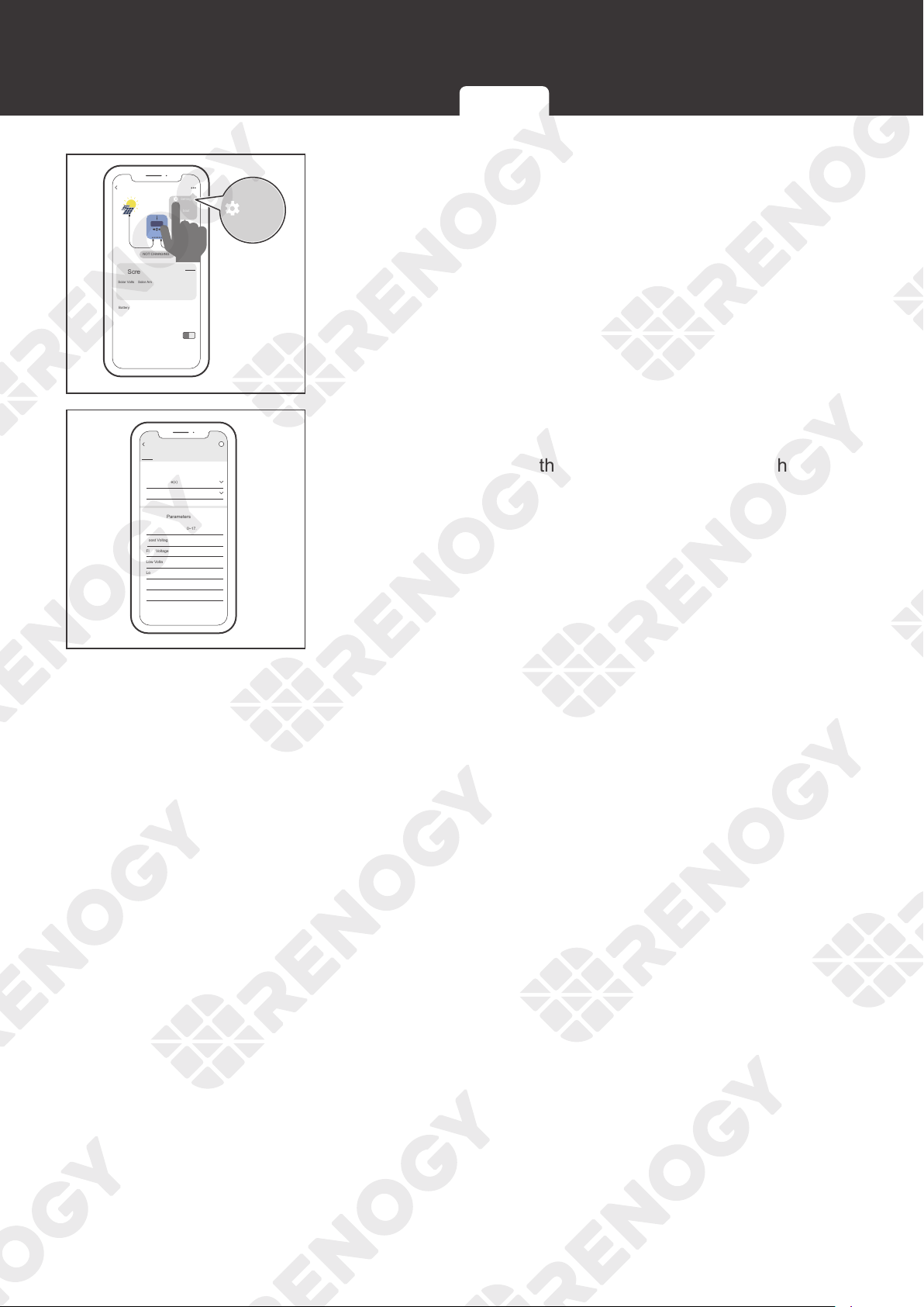
2. Tap ••• in the upper-right corner.
Setting the Battery Type Battery Charging Parameters User Mode
44
Battery Type
PV Screen
0
V 0 A 0 W
0.052 kwh
Solar Volts Solar Amps
Battery Charging Volts
Battery Charging Amps
Battery Type
Sealed 77
o
C
o
F
0 A
13.2 V
Battery Temperature
Total Energy
History
PV Watts
Produced
Settings
About
i
NOT CHARGING
RCC60RVRU
Settings
3. Tap Settings to enter the mode selection interface.
12 v
12.6 v
11.1 v
120 min
13.8 v
14.6 v
0 v
12V
Sealed
Low Voltage Warning (9.0~17.0)
Low Voltage Disconnect (9.0~17.0)
Low Voltage Reconnect (9.0~17.0)
Boost Duration
Float Voltage (9.0~17.0)
Boost Voltage (9.0~17.0)
Equalization Voltage (9.0~17.0)
System Voltage(v)
Battery Type
Advanced Parameters
General Parameters
PV
RCC60RVRU
i
4. In this interface, you can customize multiple parameters
of the battery. When the parameters are modified, Setting
Success appears on the interface, indicating that the
parameter setting is completed.
Setting the Battery Type Battery Charging Parameters User Mode
45
System Voltage
System Voltage
The charge controller is simple and easy to use. For common AGM, SLD, gel, and flooded
batteries, the charge controller can automatically identify the 12V/24V system voltage.
For the lithium battery, set the system voltage manually.
NOT
E
z
To cancel the setting and exit, press .
3s
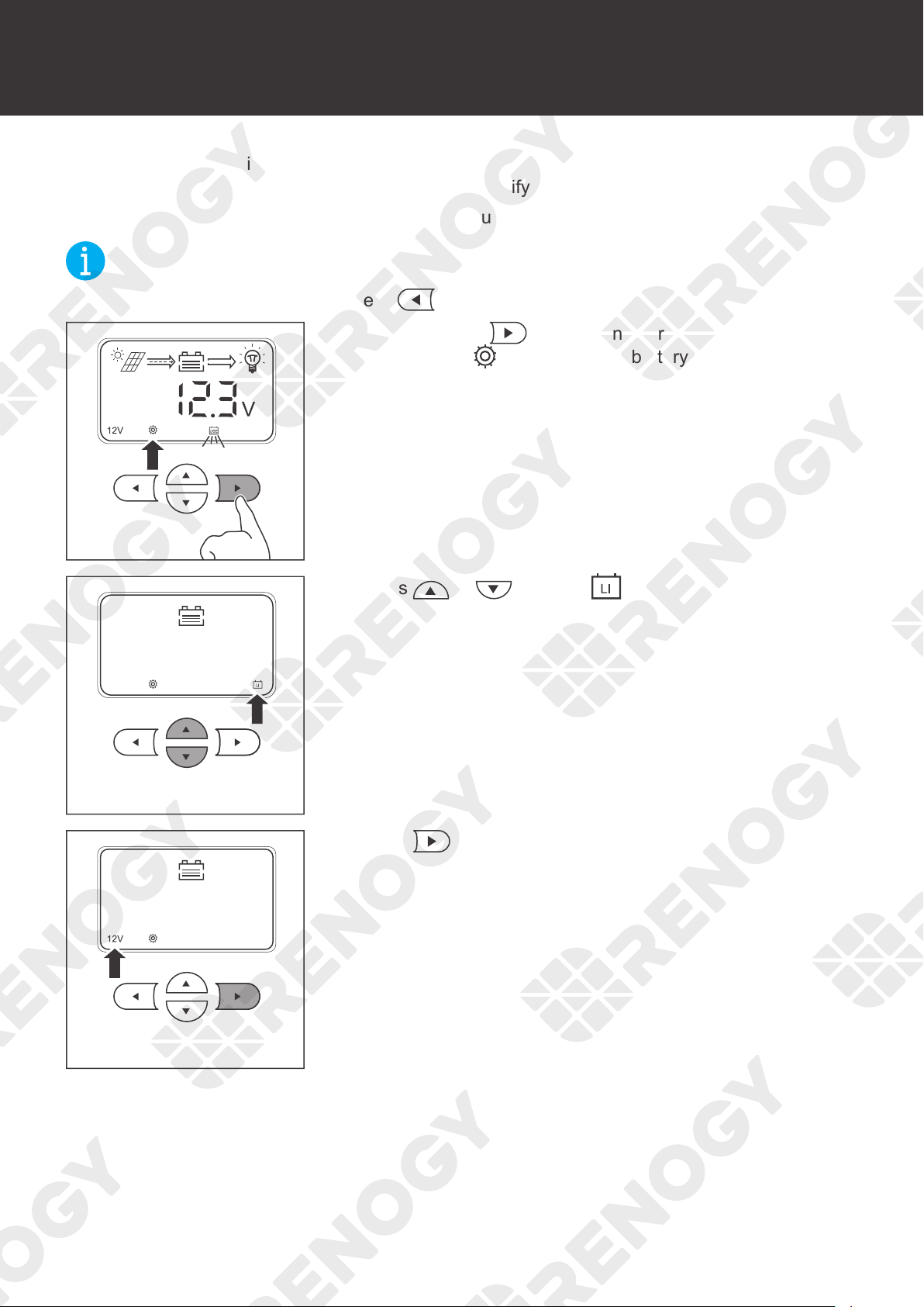
1. Press and hold in the main interface for about 3
seconds until
is lit up and the battery type icon starts
flashing.
2. Press or to select .
3. Press to set the system voltage.
46
System Voltage
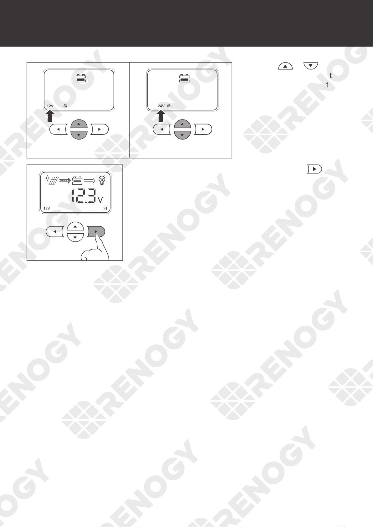
4. Press or to
select 12V or 24V system
voltage according to the
usage.
3s
5. After the settings are completed, press and hold for
about 3 seconds to save the settings.
47
Monitoring
Monitoring
The charge controller is equipped with a LCD and 4 buttons. You can check the status of the
charge controller and set parameters with the buttons.
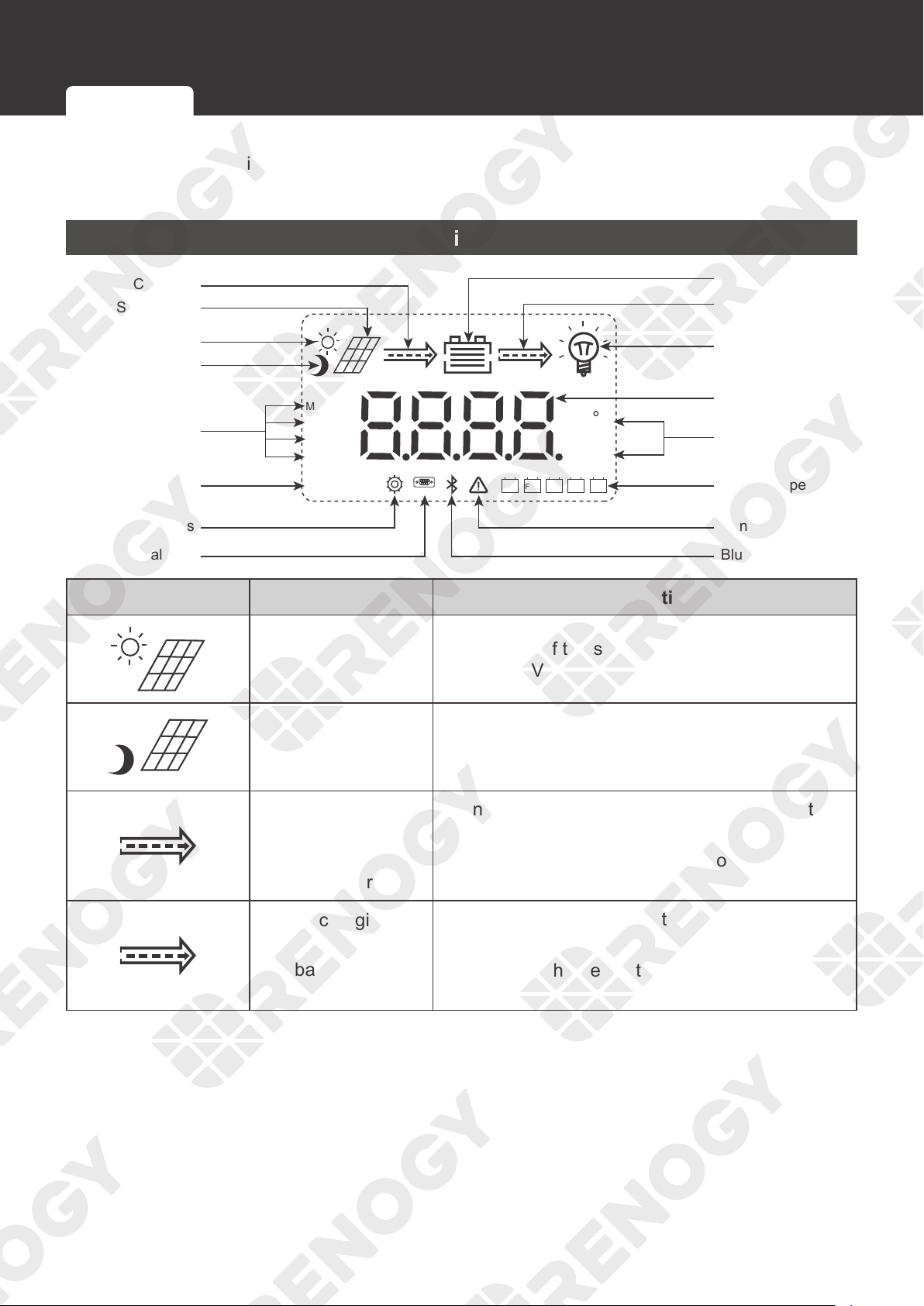
Monitoring Menu
LiSLDFLDUSE GEL
COM
12V 24V
C
V
kWAh
MPPT
BOOST
FLOAT
EQUATIZE
Nighttime
Daytime
Load
Discharging
Battery
Parameter Value
Unit
Battery Type
Solar Panel
Charging
Charging Stage
System Voltage
Settings
Serial Port
Bluetooth
Abnormality
Icon Parameter Description
Daytime Mode
The voltage of the solar panel is greater than or
equal to 10V.
Nighttime Mode The voltage of the solar panel is less than 10V.
Charging
(The arrow between
the solar panel and
the battery)
•
Dynamic: The charge controller is charging the
battery.
•
Static: The charge controller is not charging the
battery.
Discharging
(The arrow between
the battery and the
load)
•
Dynamic: The charge controller is powering the
load.
•
Static: The charge controller is not powering the
load.
Monitoring Menu
Checking Parameters
48
Monitoring
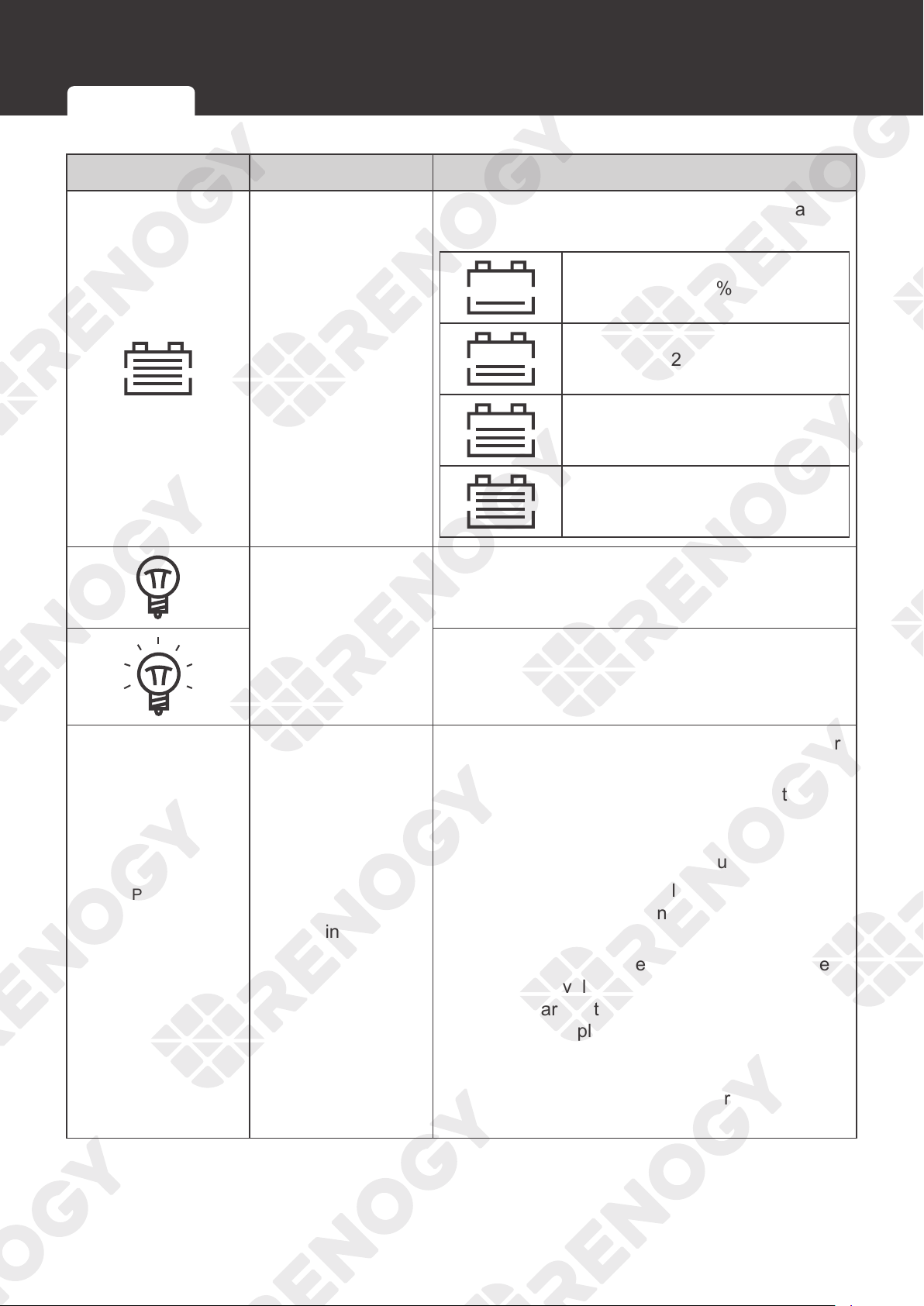
Icon Parameter Description
Battery
Indicates four levels of the battery power (based
on the battery voltage):
0-24%
25~49%
50~75%
75~100%
Load
The load is powered off or the charge controller is
not charging the load.
The load is powered on.
MPPT
BOOST
FLOAT
EQUATIZE
Charging Status
•
MPPT: The charge controller charges the battery
with all the energy from the solar panel.
•
BOOST: When the battery is charged to the
set point of the constant voltage, the charge
controller will operate in the constant charging
mode. The charging current gradually decreases.
•
FLOAT: The charge controller charges the
battery with a small current to prevent the
battery from self-discharging.
•
EQUATIZE: The charge controller charges the
battery at a level higher than the voltage that it is
typically charged to remove sulfate crystals that
build up on the plates over time and balance
the voltage of each cell. Periodic equalization
charging is beneficial to certain types of batteries
because it helps ensure the battery capacity and
maintain its runtime.
Monitoring Menu
Checking Parameters
49
Monitoring
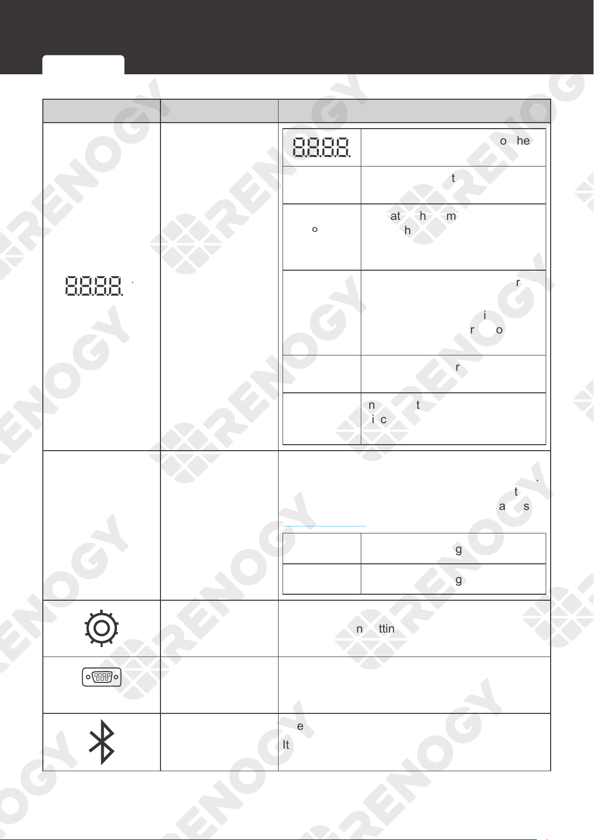
Icon Parameter Description
C
V
kWAh
Value / Unit
Indicates the parameters of the
solar panel or the battery
V
Indicates the voltage of the solar
panel or the battery
C
Indicates the temperature
of the charge controller or
the temperature sensor (if
connected)
Kw
Used by the manufacturer for
testing
It lights up for a short time when
the charge controller is powered
on.
A
Indicates the charging /
discharging current of the battery
Ah
Indicates the charging /
discharging current of the battery
in an hour
12V 24V
System Voltage
For non-lithium batteries, the charge controller
automatically identifies the voltage (12V or 24V).
For lithium batteries, you need to set the voltage
in the charge controller manually. For details, see
System Voltage.
12V
The system voltage is 12V.
24V
The system voltage is 24V.
Setting
Lights up when setting parameters
COM
Serial Port
Used by the manufacturer for testing
It lights up for a short time when the charge
controller is powered on.
Bluetooth
Used by the manufacturer for testing
It lights up for a short time when the charge
controller is powered on.
Monitoring Menu
Checking Parameters
50
Monitoring
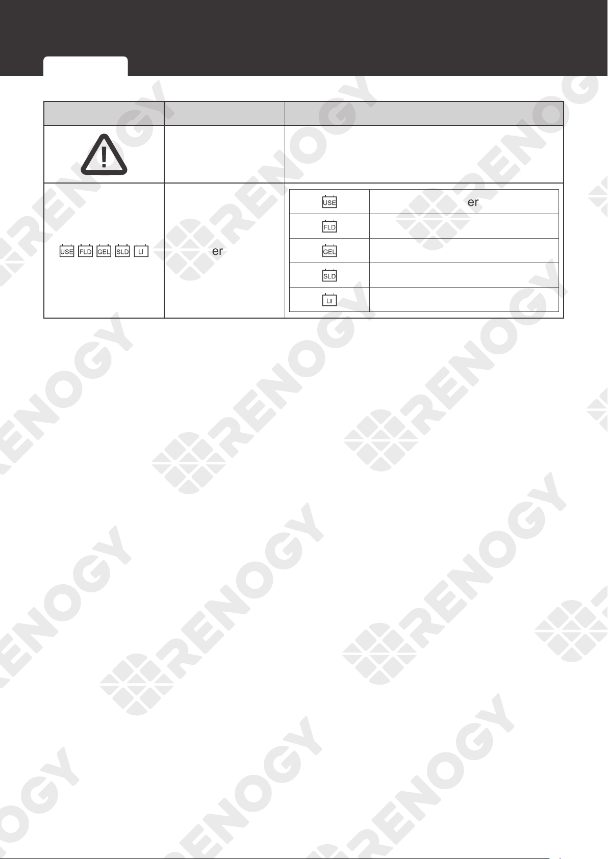
Icon Parameter Description
Abnormality
Fault
Check the error code on the LCD.
Battery Type
User-defined battery
Flooded battery
Gel battery
Sealed lead-acid battery
Lithium battery
Monitoring Menu Checking Parameters
51
Monitoring
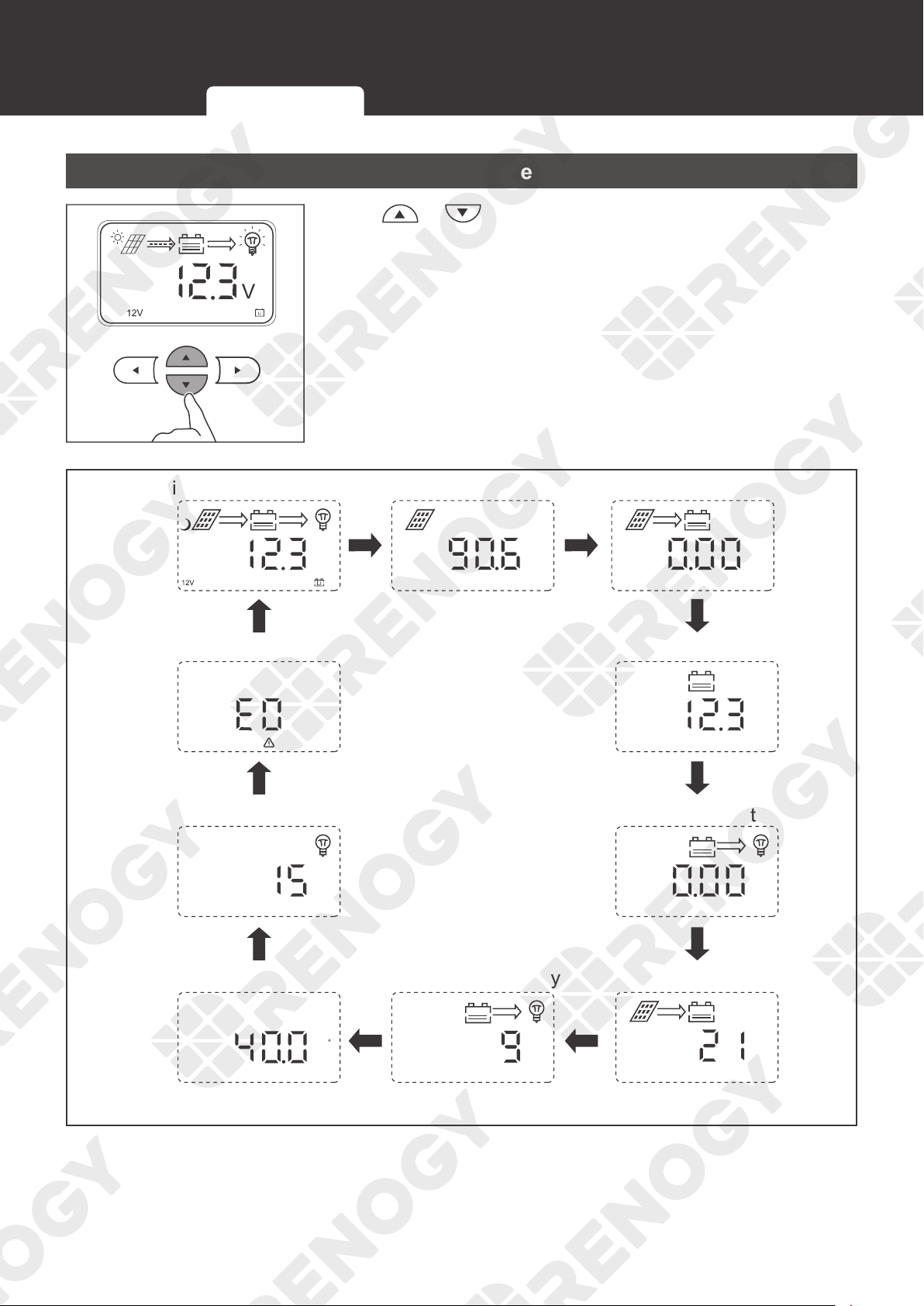
Checking Parameters
Press or to check parameters.
Main monitoring interface
V
Solar panel voltage
A
Charging current
V
Battery voltage
A
Load current
Ah
Charge capacity
Ah
Discharge capacity
C
Temperature
Load mode
Error code
Monitoring Menu
Checking Parameters
52
Load Control
Load Control
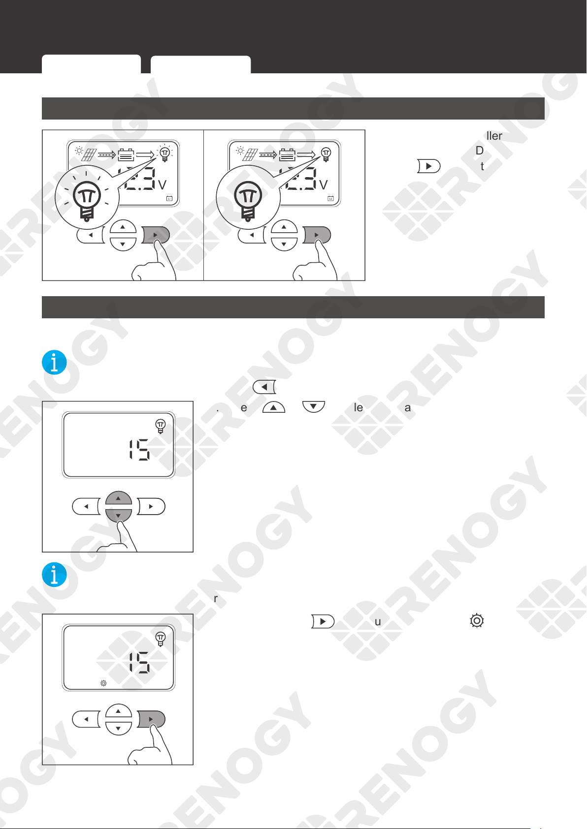
Turning Load On / Off
ON OFF
If the charge controller is
connected to the DC load,
press
to turn the load on
or off.
Switching Load Mode
You can set the way to turn on / off the DC load.
NOT
E
z
To cancel the setting and exit, press .
1. Press or to select the load mode.
NOT
E
z
This interface displays the current load mode.
3s
2. Press and hold for about 3 seconds until is lit up.
Turning Load On / Off
Switching Load Mode
53
Load Control
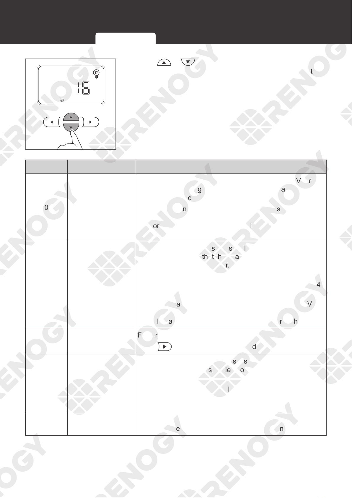
3. Press or to adjust the value. Different values
indicate the corresponding load modes. You can select the
mode according to the table below.
Value Mode Description
0 Automatic mode
When the voltage of the solar panel is less than 10V for
5 minutes, the charge controller will automatically supply
power to the load.
The charge controller will automatically stop supplying
power to the load until the solar panel voltage is greater
than or equal to 10V or the battery triggers the undervoltage
warning.
1–14 Timing mode
This parameter indicates the supply duration in hours. For
example,1 indicates that the charge controller supplies
power to the load for an hour.
When the solar panel voltage is less than 10V, the charge
controller automatically supplies power to the load for 1-14
hours (the time depends on the voltage).
If the solar panel voltage is greater than or equal to 10V or
the battery triggers the undervoltage warning, the charge
controller automatically stops supplying power to the load.
15 Manual mode
Factory default mode
Press
to turn the on / off the load.
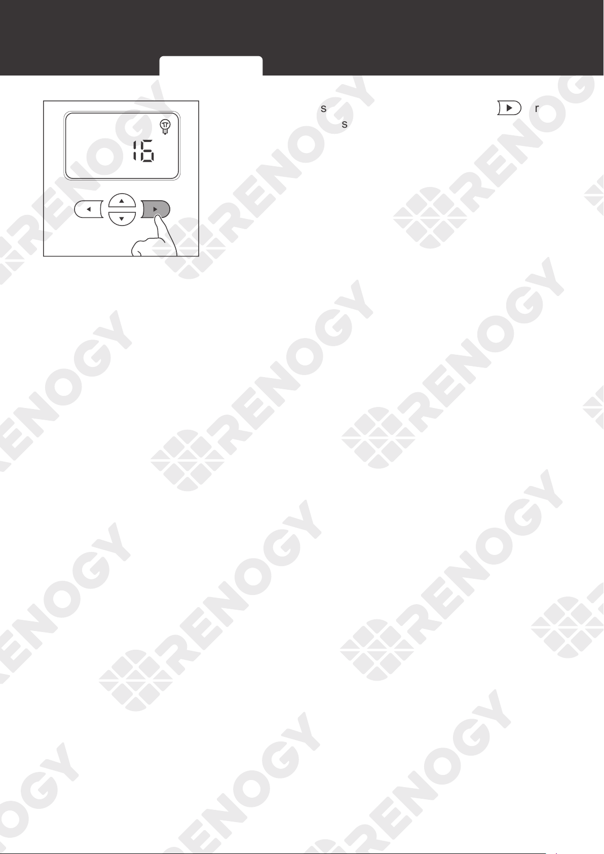
16 No delay mode
When the solar panel voltage is less than 10V, the charge
controller immediately supplies power to the load.
The charge controller will automatically stop supplying
power to the load until the solar panel voltage is greater
than or equal to 10V or the battery triggers the undervoltage
warning.
17 24-hour mode
The charge controller keeps supplying power to the load
until the battery triggers the undervoltage warning.
Turning Load On / Off
Switching Load Mode
54
Load Control
3s
4. After the settings are completed, press and hold for
about 3 seconds to save the settings.
Turning Load On / Off
Switching Load Mode
55
LED Indicators
LED Indicators
Indicator Description Function
Solar Panel LED Indicator
Indicates the charging status of the charge
controller
Battery LED Indicator Indicates the working status of the battery
Load LED Indicator Indicates the working status of the load
System Error LED Indicator
Indicates whether the charge controller is
operating normally
When the charge controller is faulty, the
indicator lights up.
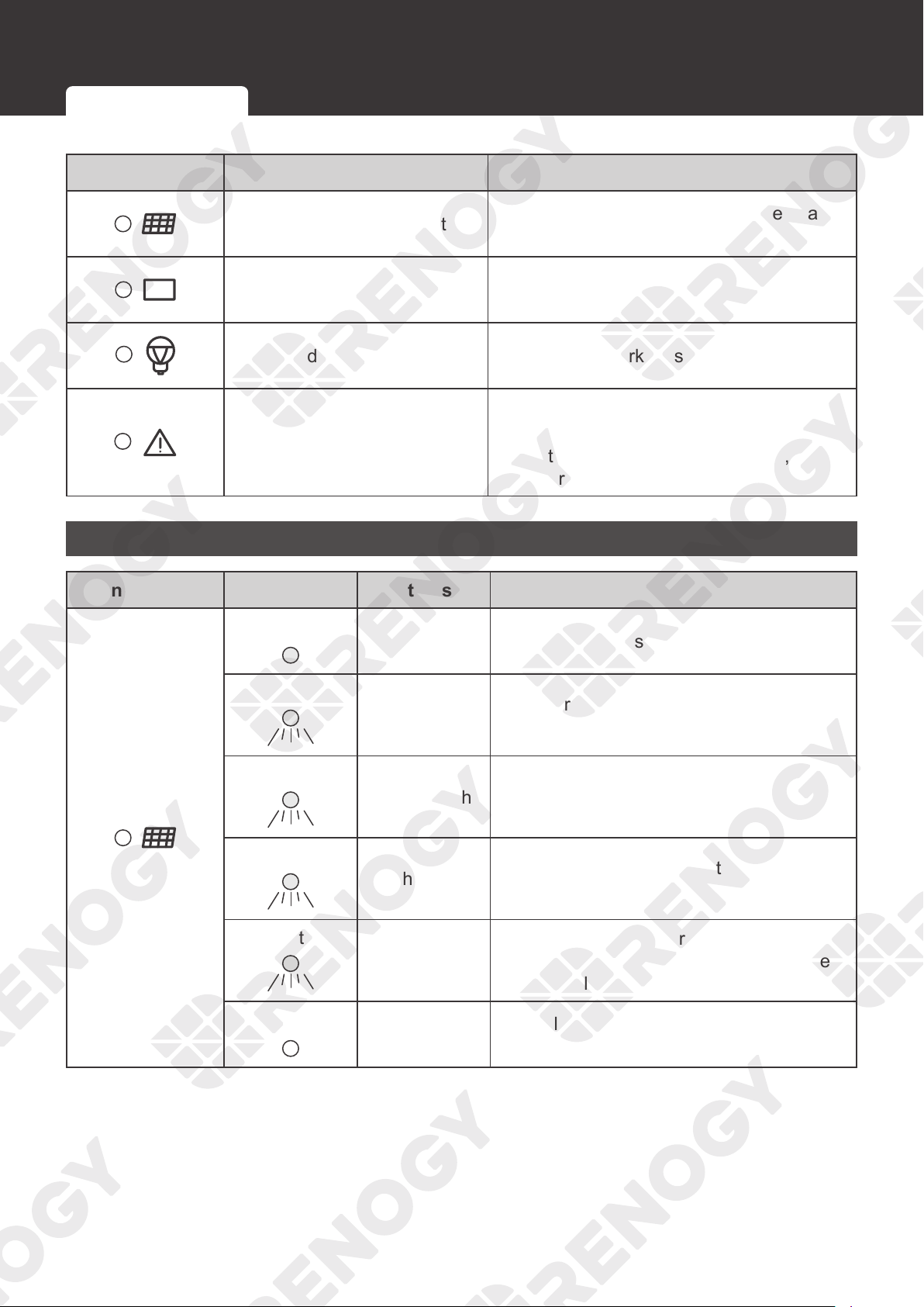
Solar Panel LED Indicator
Indicator Color Status Description
White
ON The solar panel is charging the battery.
White
Slow flash for
1s
The charge controller is in the boost
charging stage.
White
Single flash
The charge controller is in the float
charging stage.
White
Flash for 0.1s
The charge controller is in the equlization
charging stage.
White
Double flash
The solar panel is charging the battery
slowly. The current is too low. Make sure
that the solar panel is not covered.
/
OFF
The voltage of the solar panel is too low or
the solar panel is not detected.
Solar Panel LED Indicator Battery LED Indicator Load LED Indicator System Error LED Indicator
56
LED Indicators
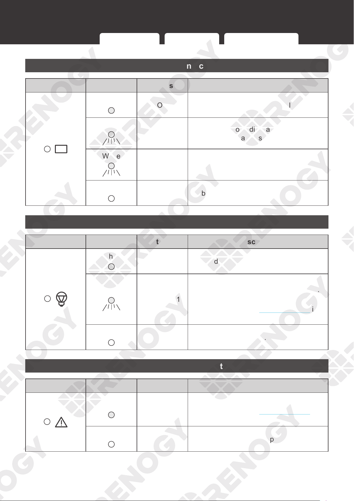
Battery LED Indicator
Indicator Color Status Description
White
ON The battery is operating normally.
White
Slow flash for
1s
The battery is overdischarging. Charge the
battery as soon as possible.
White
Flash for 0.1s
The battery voltage is too high. Disconnect
the battery from the charge controller and
check whether the battery is damaged.
/
OFF No battery is detected.
Load LED Indicator
Indicator Color Status Description
White
ON The load is powered on.
White
Flash for 0.1s
Overload or short circuit. At the same time,
the System Error LED Indicator lights up.
Check the error code for troubleshooting.
For more details, see Troubleshooting in
the user manual.
/
OFF The load is powered off.
System Error LED Indicator
Indicator Color Status Description
White
ON
Fault
For more details, see Troubleshooting in
the user manual.
/
OFF The charge controller is operating normally.
Solar Panel LED Indicator Battery LED Indicator Load LED Indicator System Error LED Indicator
57
Troubleshooting
Troubleshooting
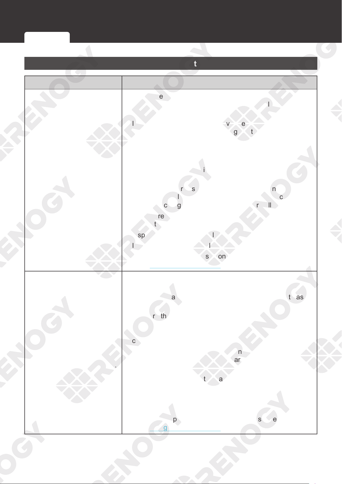
Common Faults
Fault Troubleshooting
The solar panel is connected,
but the LED indicator of the
solar panel can not light up.
This indicates the solar panel voltage may be too low or the
panel cannot be detected by the charge controller. Follow the
troubleshooting steps below:
1. Inspect the solar panel for any visible damage and make
sure it works normally. If the voltage of the solar panel is too
low at night, check it again during the day.
2. Inspect the solar panel and keep it away from the shelter.
3. Make sure the voltage of the solar panel is higher than the
battery voltage. Otherwise, the solar panel cannot charge
the battery.
4. Identify the polarities (positive and negative) on the cables
used for the solar panel. A reverse polarity contact will
cause the charge controller to work abnormally.
5. Make sure the cables of the solar panel are properly
connected to the PV+ and PV- of the charge controller.
6. Inspect the cable of the solar panel for any visible damage.
7. Inspect the fuse of the solar panel for any visible damage.
For technical support, please contact our customer service
through
renogy.com/contact-us/.
The battery is connected.
However, the indicators of the
charge controller LCD and
battery LED can not light up.
The battery needs troubleshooting if it can not be detected.
Follow the troubleshooting steps below:
1. Inspect the battery and replace it with a new one if it has
any visible damage.
2. Measure the battery voltage with a multimeter and make
sure the system voltage of the battery is 12V or 24V.
Otherwise, the battery can not be detected by the charge
controller.
3. Identify the polarities (positive and negative) on the cables
used for the battery. A reverse polarity contact will cause the
charge controller to work abnormally.
4. Make sure the cable of the battery is properly connected to
the BAT+ and BAT- of the charge controller.
5. Inspect the cable of the battery for any visible damage.
6. Inspect the fuse of the battery for any visible damage.
For technical support, please contact our customer service
through
renogy.com/contact-us/.
Common Faults Fault Codes
58
Troubleshooting
Fault Troubleshooting
The charging current of the
charge controller or the solar
panel current is lower than
expected
1. The charge controller is in the float charging stage, and the
charging current will gradually drop until the battery is fully
charged.
2. Inspect the solar panel and keep it away from the shelter.
3. Check whether the sunlight intensity is high enough.
4. If the temperature of the charge controller is too high, the
error code will not be displayed. Shut down the charge
controller until the temperature drops to a standard value.
5. Select the appropriate cables and fuses according to the
Recommended Cable and Fuse Sizing in this manual.
6. The voltage drops because the Solar Panel Extension
Cable is too long.
displays over 1 to 2
days
1. Identify the polarities (positive and negative) on the cables
used for the battery. A reverse polarity contact will cause
the charge controller to work abnormally. Connect the
battery first and then the solar panel. Otherwise, the charge
controller may be damaged.
2. Measure the voltages of the battery, BAT+, and BAT- of
the charge controller with a multimeter. If the voltages are
inconsistent, the circuit is interrupted. Inspect the circuit
and the battery fuse for any visible damage or incorrect
connection.
3. The preset battery voltage is incorrect. Measure the battery
voltage with a multimeter, and then reset the system voltage
according to the actual use. For details, refer to System
Voltage in this user manual. Disconnect the battery from the
charge controller and reconnect to it to activate the battery.
4. The discharging speed of the battery is faster than the
charging speed. Turn off or disconnect the load of the
battery and charge the battery immediately to prevent the
lithium battery from triggering BMS protection due to low
voltage.
After the voltage of the lithium battery is restored, the battery
will automatically exit the activation mode and work normally.
Common Faults Fault Codes
59
Troubleshooting
Fault Troubleshooting
The load cannot be powered
on after connection.
1. Identify the polarities (positive and negative) on the cables
used for the battery. A reverse polarity contact will cause the
load to work abnormally.
2. Make sure the load cables are properly connected.
3. Ensure that the load works normally. If the load is damaged,
replace it with a new one.
4. Check the load mode. For details, refer to
Switching Load
Mode
in this manual.
5. Check the battery voltage. If the battery voltage is too low,
charge the battery immediately.
Error Codes
1. Under normal conditions, the System Error LED Indicator of
the charge controller will not light up.
2. Press or enter the fault codes interface.
Perform troubleshooting according to steps listed in the
table below.
Icon Description Troubleshooting
No fault is detected The charge controller works normally.
Common Faults Fault Codes
60
Troubleshooting
Icon Description Troubleshooting
Battery overdischarge
Measure the battery voltage with a multimeter. If the
battery voltage is too low, disconnect the load from
the battery and charge the battery.
Battery overcharge
Measure the battery voltage with a multimeter. If the
battery voltage is too high, disconnect the battery
from the charge controller and replace the battery
with a new one.
Load short circuit
Follow the troubleshooting steps below:
1. Disconnect the load. Measure the load voltage
with a multimeter and ensure that the load voltage
matches the battery voltage.
2. Make sure the load is properly connected.
3. Inspect the load for any visible damage.
4. Disconnect the battery from the charge controller
and restart the charge controller.
5. If the fault code remains, replace the load with a
new one.
For technical support, please contact our customer
service through renogy.com/contact-us/.
Load overload
1. Check the load voltage. If the system voltage of
the charge controller is 12V, the load port can only
be connected with the 12V DC load. Otherwise,
connect the load port with the 24V DC load.
2. The maximum current of the load port on the
charge controller is 20A. Ensure that the rated
load charge current does not exceed 20A.
Charge controller
overtemperature
Follow the troubleshooting steps below:
1. Short press
or to check the temperature.
If the temperature is too high, disconnect all
devices from the charge controller immediately.
2. Ensure that the charge controller is installed on a
flat surface indoors protected from direct sunlight,
high temperature, and water.
3. Make sure there is good ventilation.
4. Select the appropriate cables and fuses according
to the
Recommended Cable and Fuse Sizing in
this manual.
5. Reconnect the charge controller after the
temperature drops to a standard value.
Common Faults Fault Codes
61
Troubleshooting
Icon Description Troubleshooting
Solar panel
overcurrent
1. Make sure the solar panel is not short circuited.
2. Ensure that the power of the solar panel does not
exceed the rated power of the charge controller.
Solar panel
overvoltage
The maximum DC input voltage of the charge
controller is 100V. Make sure the voltage of the solar
panel array is less than or equal to 100V. Otherwise,
reduce the number of solar panels.
NOT
E
z
For technical support, please contact our customer service through renogy.com/contact-us/.
Common Faults Fault Codes
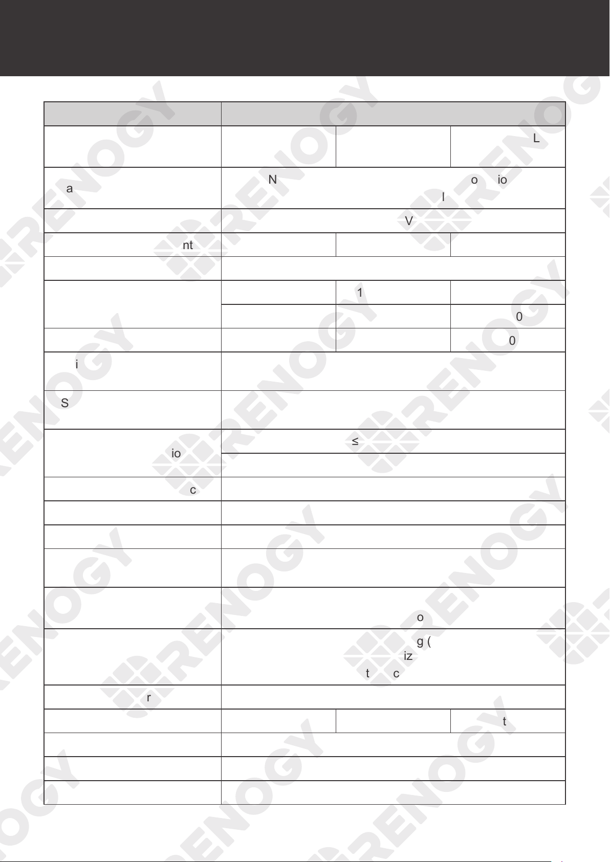
62
Technical Specifications
Technical Specifications
Parameter Value
Model
RNG-CTRL
-RVR20
RNG-CTRL
-RVR30
RNG-CTRL
-RVR40
Rated Battery Input Voltage
Non-lithium:12V/24V (automatic recognition)
Lithium:
12V/24V (manual setting)
Battery Input Voltage Range 10V to 32V DC
Rated Charge Current 20A 30A 40A
Rated Load Charge Current 20A
Rated Solar Input Power
12V @ 260W 12V @ 400W 12V @ 520W
24V @ 520W 24V @ 800W 24V @ 1040W
Maximum Solar Input Power 520W 800W 1040W
Maximum Solar Input Voltage
(Voc)
100V DC
Solar Input Voltage Range
(Voc)
15V to 100V DC
Power Consumption
≤100mA @12V
≤58mA @24V
MPPT Tracking Efficiency >99%
Conversion Efficiency ≤98%
Charger Efficiency >
95%
MPPT Operating Voltage
Range
17V to 100V DC
Temperature Compensation
Non-lithium: -3mV / °C / 2V
Lithium: 0mV / °C / 2V; no compensation
Charger Algorithm
Lead acid battery: 3-stage charging (Bulk, Boost, and Float)
with Equalization
Lithium batteries: 2-stage charging (Bulk and Boost)
Charger Preset AGM, Gel, Flooded, Li, User-defined
Cable Size 8 AWG to 12 AWG 8 AWG to 10 AWG 6 AWG to 8 AWG
Grounding Common Negative
Communication RS232 Modbus
Operating Temperature
-31°F to 113°F / -35
℃
to 45
℃
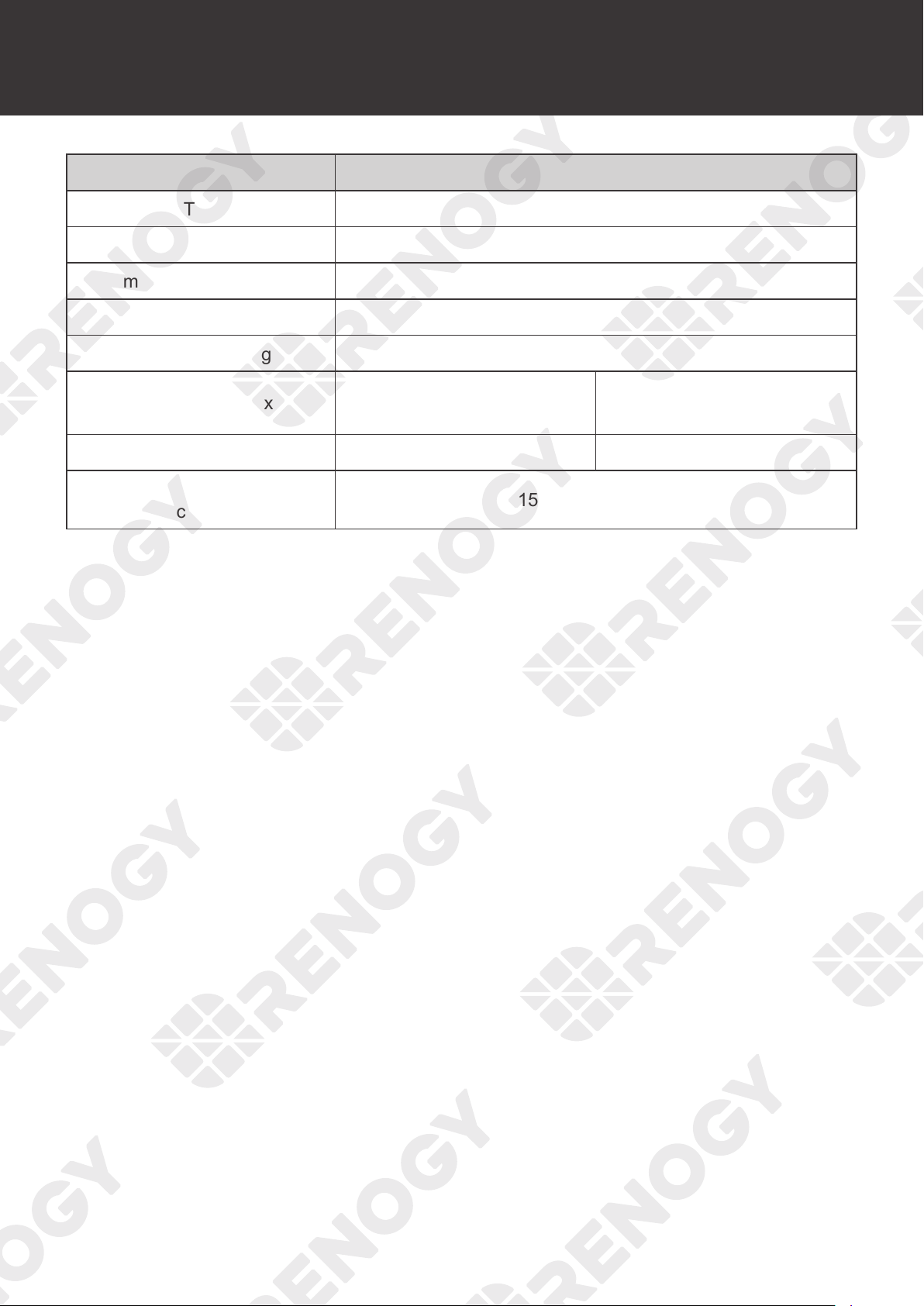
63
Technical Specifications
Parameter Value
Storage Temperature
-31°F to 167°F or -35
℃
to 75
℃
Humidity 0% to 95% RH
Maximum Operating Altitude ≤3000m
Cooling Heat Sink
Enclosure Rating IP32
Dimensions (L x W x H)
8.27 x 5.95 x 2.69 in
210 x 151 x 68 mm
9.38 x 6.78 x 3.05 in
238 x 172 x 77 mm
Weight 3.1 lbs / 1.4 kg 4.4 lbs / 2.0 kg
Regulatory and Safety
Specifications
FCC Part 15 Class B, CE, RoHS, RCM
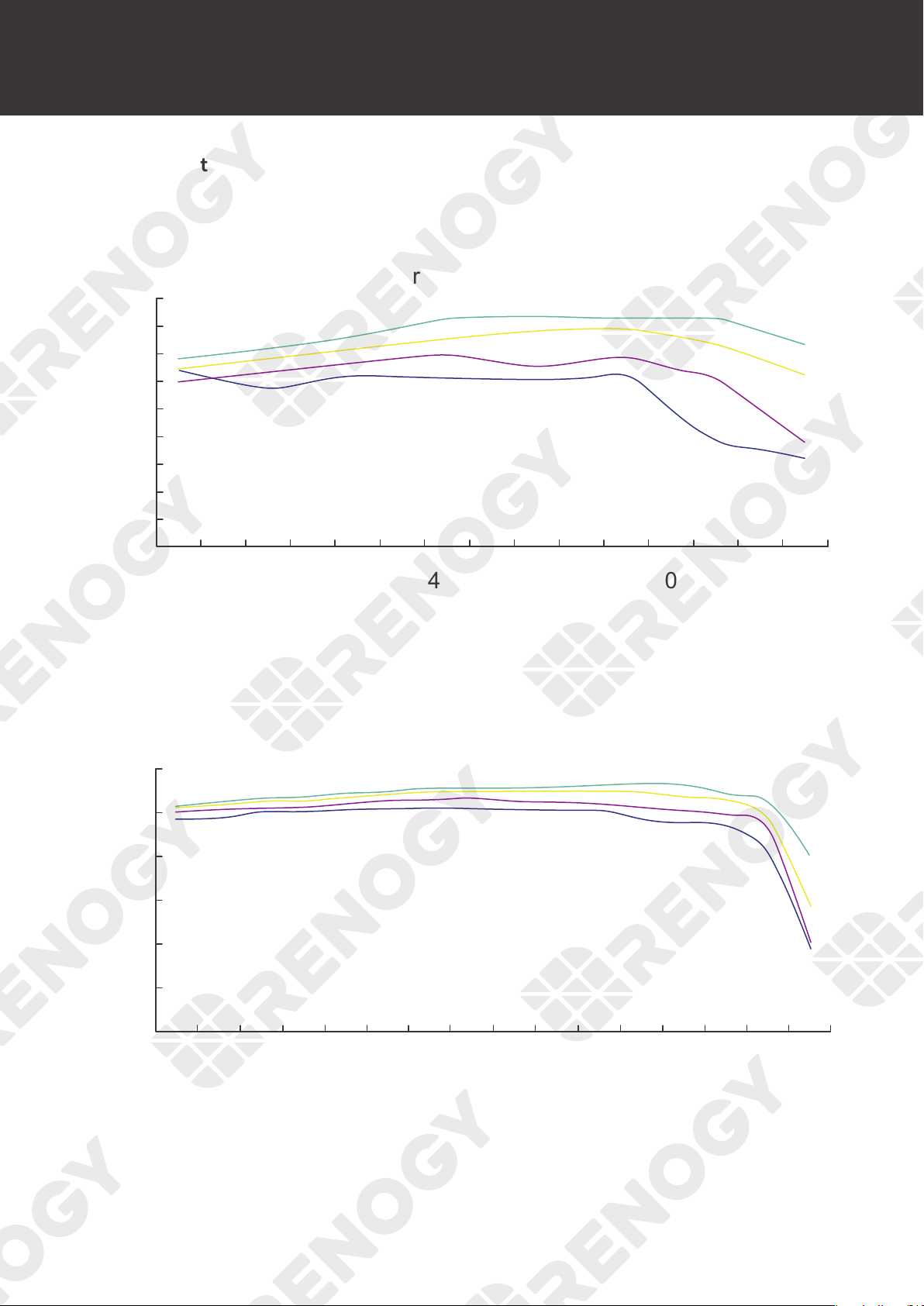
64
MPPT Conversion Efficiency
MPPT Conversion Efficiency
Light Intensity: 1000W/m
2
Temperature: 25°C
96%
95%
94%
93%
92%
91%
90%
89%
88%
87%
550 525 500 475 450 425 400 375 350 300 250 200 150
20 Vmp
40 Vmp
60 Vmp
75 Vmp
100 50
()
Output power(W)
MPPT 12V conversion efficiency (12V battery)
MPPT 24V conversion efficiency (24V battery)
98%
96%
94%
92%
90%
88%
86%
1100 1000 900 800 600 500 300 100
40 Vmp
50 Vmp
60 Vmp
75 Vmp
Output power(W)
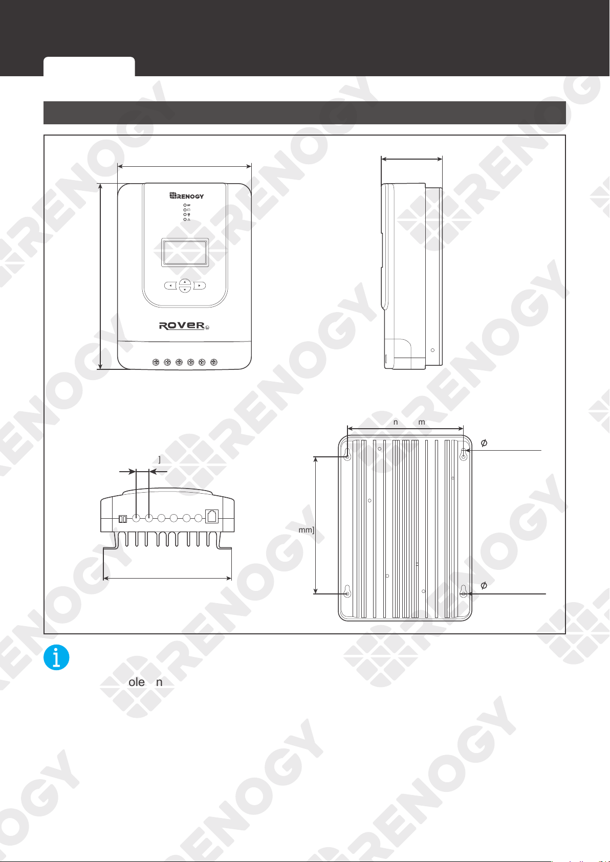
65
Dimensions
Dimensions
RNG-CTRL-RVR20
0.2 in [4.5 mm]
0.4 in [9 mm]
5.95 in [151 mm]
2.69 in [68 mm]
5.2 in [131 mm]
6.1 in
[154 mm]
8.27 in
[210 mm]
5.7 in [143.6 mm]
0.5 in
[13.9 mm]
Temp. PV+ PV- BAT+ BAT- LOAD+ LOAD-
RS232
NOT
E
z
Dimension tolerance: ±0.2 in (0.5 mm)
RNG-CTRL-RVR20 RNG-CTRL-RVR30 or RNG-CTRL-RVR40
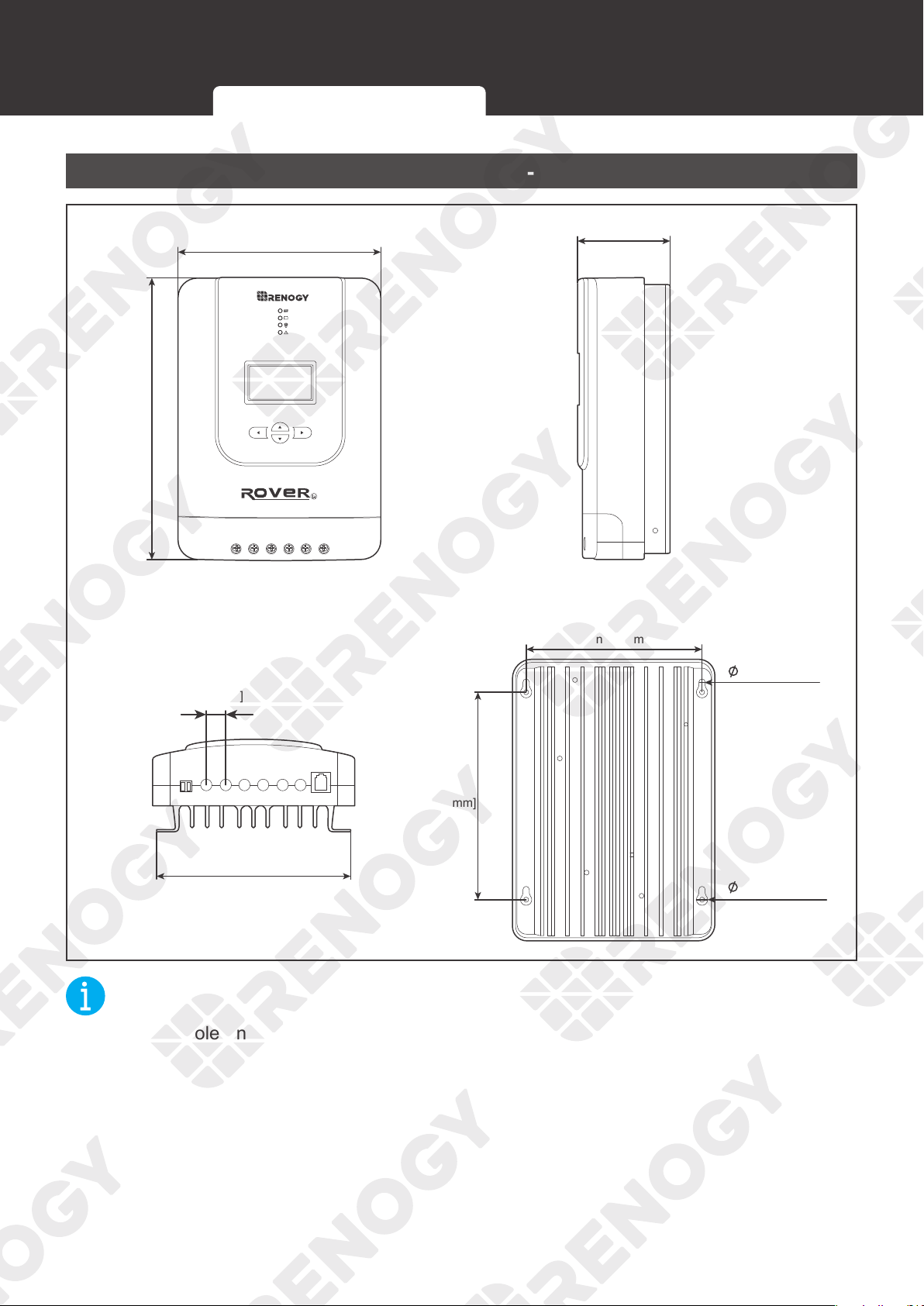
66
Dimensions
RNG-CTRL-RVR30 or RNG-CTRL-RVR40
Temp. PV+ PV- BAT+ BAT- LOAD+ LOAD-
RS232
0.2 in [4.5 mm]
0.4 in [10 mm]
6.78 in [172 mm]
3.05 in [77 mm]
5.8 in [147 mm]
7.0 in
[180 mm]
9.38 in
[238 mm]
6.6 in [167.6 mm]
0.7 in
[18.0 mm]
NOT
E
z
Dimension tolerance: ±0.2 in (0.5 mm)
RNG-CTRL-RVR20 RNG-CTRL-RVR30 or RNG-CTRL-RVR40
67
Maintenance
Maintenance
Inspection
For optimum performance, it is recommended to perform these tasks regularly.
z
Check the appearance of the charge controller to make sure it is clean and dry.
z
Ensure the charge controller is mounted in a clean, dry, and ventilated area.
z
Ensure there is no damage or wear on the cables. Ensure the firmness of the Anderson
connectors and check if there are any loose, damaged or burnt connections.
z
Make sure that the indicators are in normal state.
z
Ensure there is no corrosion, insulation damage, or discoloration marks of overheating or
burning.
NOT
E
z
In some applications, corrosion may exist around the contacts inside the Anderson
connector.
Corrosion can loosen springs and increase resistance, leading to premature connection
failure. Apply dielectric grease to each connector contact periodically. Dielectric grease
repels moisture and protects the connector contacts from corrosion.
WARNIN
G
z
Risk of electric shock! Make sure that all power is turned off before touching the terminals on
the charge controller.
Cleaning
Follow the steps below to clean the charge controller regularly.
z
Disconnect all Anderson connectors that are connected to the charge controller.
z
Wipe the housing and connector contacts with a dry cloth or non-metallic brush. If it is still
dirty, you can use household cleaners.
z
Dry the charge controller with a clean cloth and keep the area around the charge controller
clean and dry.
z
Make sure the charge controller is completely dry before reconnecting it to the solar panel
and the battery.
z
When reconnecting, the battery must be connected first, then the solar panel.
Storage
Follow the tips below to ensure that the charge controller is stored well.
z
Disconnect all Anderson connectors that are connected to the charge controller.
z
By applying dielectric grease to each connector contact, the dielectric grease repels
moisture and protects the connector contacts from corrosion.
z
Store the charge controller in a well-ventilated, dry and clean environment with a
temperature between -1
3°F and 149°F.
Inspection Cleaning Storage
68
Emergency Responses
Emergency Responses
In the event of any threat to health or safety, always begin with the steps below before
addressing other suggestions.
z
Immediately contact the fire department or other relevant emergency response team.
z
Notify all people who might be affected and ensure that they can evacuate the area.
WARNIN
G
z
ONLY perform the suggested actions below if it is safe to do so.
Fire
1. Disconnect all cables connected to the charge controller.
2. Put out the fire with a fire extinguisher. Acceptable fire extinguishers include water, CO
2
, and
ABC.
WARNIN
G
z
Do not use type D (flammable metal) fire extinguishers.
Flooding
1. If the charge controller is submerged in water, stay away from the water.
2. Disconnect all cables connected to the charge controller.
Smell
1. Disconnect all the cables from the charge controller.
2. Ensure that nothing is in contact with the charge controller.
3. Ventilate the room.
Noise
1. Disconnect all cables connected to the charge controller.
2. Make sure no foreign objects are stuck in the Anderson connector.
Fire Flooding Smell Noise
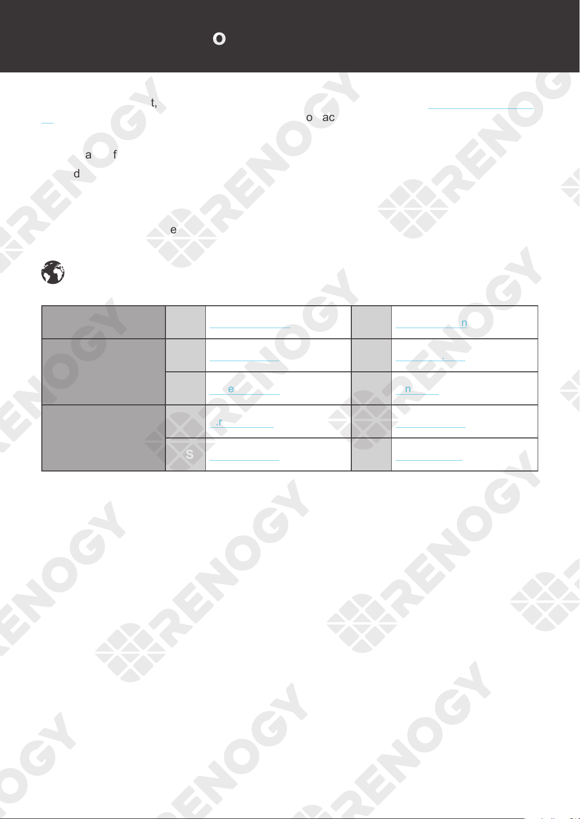
69
Technical Support
For additional support, contact the Renogy technical support team through renogy.com/contact-
us. Have the following information available when contacting Renogy.
z
Owner name
z
Contact information
z
Order number
z
Purchase channel
z
Serial number
z
Brief description of the issue
Renogy offers premium services worldwide:
North America US
www.renogy.com
CN
www.renogy.cn
Asia / Pacific
UK
uk.renogy.com
CA
ca.renogy.com
AU
au.renogy.com
JP
renogy.jp
Europe
FR
fr.renogy.com
DE
de.renogy.com
ES
es.renogy.com
KR
kr.renogy.com
Technical Support
70
FCC Statement
This device complies with Part 15 of the FCC Rules. FCC ID: 2ANPBRSMLP4-G2. Operation is
subject to the following two conditions:
(1) This device may not cause harmful interference.
(2) This device must accept any interference received, including interference that may cause
undesired operation.
This equipment has been tested and found to comply with the limits for a Class B digital
device, pursuant to Part 15 of the FCC Rules. These limits are designed to provide reasonable
protection against harmful interference in a residential installation. This equipment generates,
uses and can radiate radio frequency energy and, if not installed and used in accordance with
the instructions, may cause harmful interference to radio communications. However, there is no
guarantee that interference will not occur in a particular installation. If this equipment does cause
harmful interference to radio or television reception, which can be determined by turning the
equipment off and on, the user is encouraged to try to correct the interference by one or more of
the following measures:
(1) Orient or relocate the receiving antenna.
(2) Increase the separation between the equipment and receiver.
(3) Connect the equipment into an outlet on a circuit different from that to which the receiver is
connected.
(4) Consult the dealer or an experienced radio / TV technician for help.
FCC Radiation Exposure Statement
This equipment complies with FCC radiation exposure limits set forth for an uncontrolled
environment. This equipment should be installed and operated with minimum distance 20 cm
between the radiator & your body.
Manufacturer: RENOGY New Energy Co.,Ltd
Address: No.66, East Ningbo Road Room 624-625
Taicang German Overseas Students Pioneer Park
JiangSu 215000 CN
Manufacturer: RENOGY New Energy Co.,Ltd
Address: No.66, East Ningbo Road Room 624-625
Taicang German Overseas Students Pioneer Park
JiangSu 215000 CN
EVATOST CONSULTING LTD
Centre, Taffs Well, Cardiff, Wales, CF15 7QR
Suite 11, First Floor, Moy Road Business
eVatmaster Consulting GmbH
60325 Frankfurt am Main, Germany
contact@ evatmaster. com
Battinastr.30
UK REP
EC REP
Renogy reserves the right to change the contents of this manual without notice.
Visit
renogy.com to find relevant documentation or get more support via "Contact Us".
Join the Renogy Power Plus Community
by downloading the DC Home App.
Find your e-warranty here, and more.
RENOGY.COM