
Section
Name
Table of
Contents
Important Safety
Instructions
07 Safety Warning Labels / Serial Number
Assembly
09 Specifications
10 Parts, Hardware & Tools
12 Assembly
23 Installing the Shoe Clips (Cleats)
24 Adjustments
Features
27 Console
29 JRNY®
29 Charging & Bluetooth®
29 Heart Rate
Operations
32 Operations
34 Getting Started
36 Console Setup Mode
38 Maintenance
40 Troubleshooting
Warranty
45 Warranty (US/Canada only)

Owner’s Manual 3
Purchasing Information
Assembly / Owner’s Manual 3
To validate warranty support, keep the original proof of purchase and record the following
information:
Serial Number
Date of Purchase
If purchased in US/Canada:
To register your product warranty, go to: www.bowflex.com/register or call 1 (800) 605–3369.
If purchased outside US/Canada:
To register your product warranty, contact your local distributor.
For details regarding product warranty or if you have questions or problems with your product, please contact your local distributor. To
find your local distributor, go to: global.bowflex.com
BowFlex Inc., 5415 Centerpoint Parkway, Groveport, OH 43125 USA, www.bowflex.com - Customer Service: North America (800) 605-
3369, [email protected] | BowFlex (Shanghai) Fitness Equipments Co, Ltd, Room 1701 &1702, 1018 Changning Road, Changning District,
Shanghai, China 200042, www.bowflex.cn - 86 21 6115 9668 | outside U.S. global.bowflex.com | Printed in China | © 2023 Bowflex, Inc. |
Bowflex, the Bowflex logo, and JRNY are trademarks owned or licensed by BowFlex Inc., registered or otherwise protected by common
law in the U.S. and other countries. Other trademarks are the property of their respective owners. The Bluetooth® word mark and logos are
registered trademarks owned by Bluetooth SIG, Inc., and any use of such marks by BowFlex Inc. is under license.
Original Manual - English Version Only
Scan the QR code to download the
JRNY™ App and get started today.

Section
Name
4 Owner’s Manual
Important
Safety
Instructions

Owner’s Manual 5
Important Safety Instructions
When using an electrical appliance, basic
precautions should always be followed,
including the following:
This icon means a potentially hazardous situation which,
if not avoided, could result in death or serious injury.
Obey the following warnings:
Read and understand all warnings on this machine.
Carefully read and understand the Assembly instructions.
• Keep bystanders and children away from the product you are
assembling at all times.
• Do not connect power supply to the machine until instructed to do
so.
• To reduce the risk of electrical shock or unattended/unsupervised
usage, always unplug the AC Adapter from the wall outlet and
the machine and wait 5 minutes before cleaning, maintaining or
repairing the machine. Place the AC Adapter in a secure location.
• Do not assemble this machine outdoors or in a wet or moist
location.
• Make sure assembly is done in an appropriate work space away
from foot traic and exposure to bystanders.
• Some components of the machine can be heavy or awkward. Use a
second person when doing the assembly steps involving these parts.
Do not do steps that involve heavy lifting or awkward movements
on your own.
• Set up this machine on a solid, level, horizontal surface.
• Do not try to change the design or functionality of this machine.
This could compromise the safety of this machine and will void the
warranty.
• If replacement parts are necessary use only genuine replacement
parts and hardware supplied by BowFlex. Failure to use genuine
replacement parts can cause a risk to users, keep the machine from
operating correctly and void the warranty.
• Do not use or put the machine into service until the machine has
been fully assembled and inspected for correct performance in
accordance with the Manual.
• Read and understand the complete Manual supplied with this
machine before first use. Keep the Manual for future reference.
• Do all assembly steps in the sequence given. Incorrect assembly
can lead to injury or incorrect function.
• Connect this machine to a properly grounded or earthed outlet
only.
• Keep the AC Adapter away from heat sources and hot surfaces.
•
SAVE THESE INSTRUCTIONS.

6 Owner’s Manual
Important Safety Instructions
Before using this equipment, obey the
following warnings:
Read and understand the complete Manual. Keep the
Manual for future reference.
Read and understand all warnings on this machine. If at
any time the Warning labels become loose, unreadable
or dislodged, replace the labels. If purchased in US/
Canada, contact Customer Service for replacement labels.
If purchased outside US/Canada, contact your local
distributor for them.
• Children must not be let on or near to this machine. Moving parts
and other features of the machine can be dangerous to children.
• Not intended for use by anyone under 14 years of age.
• Consult a physician before you start an exercise program or a new
health and diet plan. Stop exercising if you feel pain or tightness
in your chest, become short of breath, or feel faint. Contact
your doctor before you use the machine again. Use the values
calculated or measured by the machine’s computer for reference
purposes only. The heart rate displayed on the console is an
approximation and should be used for reference only.
• Before each use, examine this machine for damage to power cord,
power receptacle, loose parts or signs of wear. Do not use if found
in this condition. Monitor the Seat, Pedals and Crank Arms closely.
If purchased in US/Canada, contact Customer Service for repair
information. If purchased outside US/Canada, contact your local
distributor for repair information.
• This appliance should only be used with the power supply unit
provided, or a replacement power supply unit supplied from
BowFlex Inc.
• Maximum user weight limit: 150 kg (330 lbs.). Do not use if you are
over this weight.
• The BowFlex™ IC Bike SE machine is for home use only. Do not
place or use the machine in a commercial or institutional setting.
This includes gyms, corporations, work places, clubs, fitness
centers and any public or private entity that has a machine for use
by its members, customers, employees or ailiates.
• The BowFlex™ IC Bike SEi machine is intended for Home/
Consumer or Studio/Institutional use. When the machine is placed
into a Studio/Institutional environment, usage should be limited to
less than 3 hours per day, and it should only be used in areas where
access and control of the machine are managed and supervised
by approved sta. The degree of management depends among
other things on the specific setting in which the machine is placed,
security of that environment, and familiarity of the users with the
equipment. Because others will have used the machine previously,
make sure the seat, pedals and handlebars are correctly adjusted,
tightened and secured.
• Do not wear loose clothing or jewelry. This machine contains
moving parts. Do not put fingers or other objects into moving parts
of the exercise equipment.
• Always wear rubber soled athletic shoes or cycling shoes with
cleats when you use this machine. Do not use the machine with
bare feet or only wearing socks.
• Set up and operate this machine on a solid, level, horizontal
surface.
• Do not step o the machine until the Pedals have fully stopped.
• Make the Pedals stable before you step on them. Use caution
when you step on and o the machine.
• Disconnect all power before servicing this machine.
• Do not operate this machine outdoors or in moist or wet locations.
Keep the Pedals clean and dry.
• Keep at least 0.6 m (24 in) along the side used to access the
machine and to the rear of the machine clear. This is the
recommended safe distance for access, passage and emergency
dismounts from the machine. Keep third parties out of this space
when machine is in use.
• Do not over exert yourself during exercise. Operate the machine in
the manner described in this manual.
• Perform all regular and periodic maintenance procedures
recommended in the Owner’s Manual.
• Do not drop or put objects into any opening of the machine.
• Correctly adjust and safely engage all Positional Adjustment
Devices. Make sure that the Adjustment Devices do not hit the
user.
• Exercise on this machine requires coordination and balance. Be
sure to anticipate that changes in speed and resistance level can
occur during workouts, and be attentive in order to avoid loss of
balance and possible injury.
• Since this machine operates with a fixed gear, do not back, or
reverse, pedal. Doing so may loosen the Pedals, which could result
in damage to the machine and/or injury to the user. Never operate
this machine with loose Pedals.
• For safe storage of the machine, remove the power supply
and place in a secure location. Tighten the Brake/Resistance
Adjustment Knob as described until the Flywheel is locked. Place
the machine in a secure location away from children and pets.
• This appliance is not intended for use by persons (including
children) with reduced physical, sensory or mental capabilities,
or lack of experience and knowledge, unless they have been given
supervision or instruction concerning use of the appliance by a
person responsible for their safety.
• This bike cannot stop the Pedals independently of the Flywheel.
Reduce the pace to slow the Flywheel and Pedals to a stop. Do not
dismount the bike until the Pedals have come to a complete stop.
Be aware that the moving Pedals can strike the backs of the legs.
• Children should be supervised to ensure that they do not play with
the appliance.
•
SAVE THESE INSTRUCTIONS.
Owner’s Manual 7
Safety Warning Labels
FCC Compliance
Changes or modifications to this unit not expressly
approved by the party responsible for compliance could
void the user’s authority to operate the equipment.
This product complies with part 15 of the FCC rules. Operation
is subject to the following two conditions: (1) This device may
not cause harmful interference, and (2) this device must accept
any interference received, including interference that may cause
undesired operation.
Note: This product has been tested and found to comply with
the limits for a Class B digital device, pursuant to CFR47 Part 15
Subpart B of the FCC Rules. These limits are designed to provide
reasonable protection against harmful interference in a residen-
tial installation. This equipment generates radio frequency energy
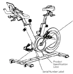
Product
Specification
Label
WARNING!
Read, understand and obey all warnings on this machine. Keep
children and pets away. Not intended for use by anyone under 14
years of age. Refer to the Owner’s Manual for additional warnings and
safety information. Injury or death is possible if caution is not used
while using this machine. The maximum user weight for this machine
is 330 lbs (150 kg.). The heart rate displayed is an approximation and
should be used for reference only. For Consumer Use Only. Consult a
physician prior to using any exercise equipment. Set up and operate
the stationary exercise bicycle on a solid level surface. Care should
be taken in mounting and dismounting the stationary exercise
equipment. Before dismounting, bring the machine to a complete
stop. Spinning pedals can cause injury. This exercise bicycle does not
have a freewheel and pedal speed must be reduced in a controlled
manner.
(Label is only available in English and French Canadian.)
and, if not installed and used in accordance with the instructions,
may cause harmful interference to radio communications.
However, there is no guarantee that interference will not occur in a
particular installation. In the unlikely event that this equipment does
cause harmful interference to radio or television reception, which
can be determined by turning the equipment o and on, the user is
encouraged to try to correct the interference by one or more of the
following measures:
• Reorient or relocate the receiving antenna.
• Increase the separation between the equipment and receiver.
• Consult the dealer or an experienced radio/TV technician for
help.
This product complies with the European Radio Equipment
Directive 2014/53/EU
Serial Number Label
BowFlex™ IC Bike SE
WARNING!
Read, understand and obey all warnings on this machine. Keep children and pets away. Not intended for use by anyone under 14 years
of age. Refer to the Owner’s Manual for additional warnings and safety information. Injury or death is possible if caution is not used
while using this machine. The maximum user weight for this machine is 330 lbs (150 kg.). The heart rate displayed is an approximation
and should be used for reference only. Use the stationary training equipment in a supervised environment. Consult a physician prior
to using any exercise equipment. Set up and operate the stationary exercise bicycle on a solid level surface. Care should be taken in
mounting and dismounting the stationary exercise equipment. Before dismounting, bring the machine to a complete stop. Spinning
pedals can cause injury. This exercise bicycle does not have a freewheel and pedal speed must be reduced in a controlled manner.
BowFlex™ IC Bike SEi

Section
Name
8 Owner’s Manual
Assembly
Owner’s Manual 9
Specifications / Before Assembly
Maximum User Weight 150 kg (330 lb.)
Total Surface Area
(Footprint) of Equipment
7570cm
2
(1176in
2
)
Machine Weight 61.4 kg (135.4 lbs.)
Weight of Dumbbells 2.7 kg (6 lbs.)
Power Requirements
(AC Adapter)
Input Voltage: 90-240V AC, 50-60Hz, 1.5A
Output Voltage: 12V DC, 3A
DO NOT dispose of this product as refuse. This product is to be
recycled. For proper disposal of this product, please follow the
prescribed methods at an approved waste center.
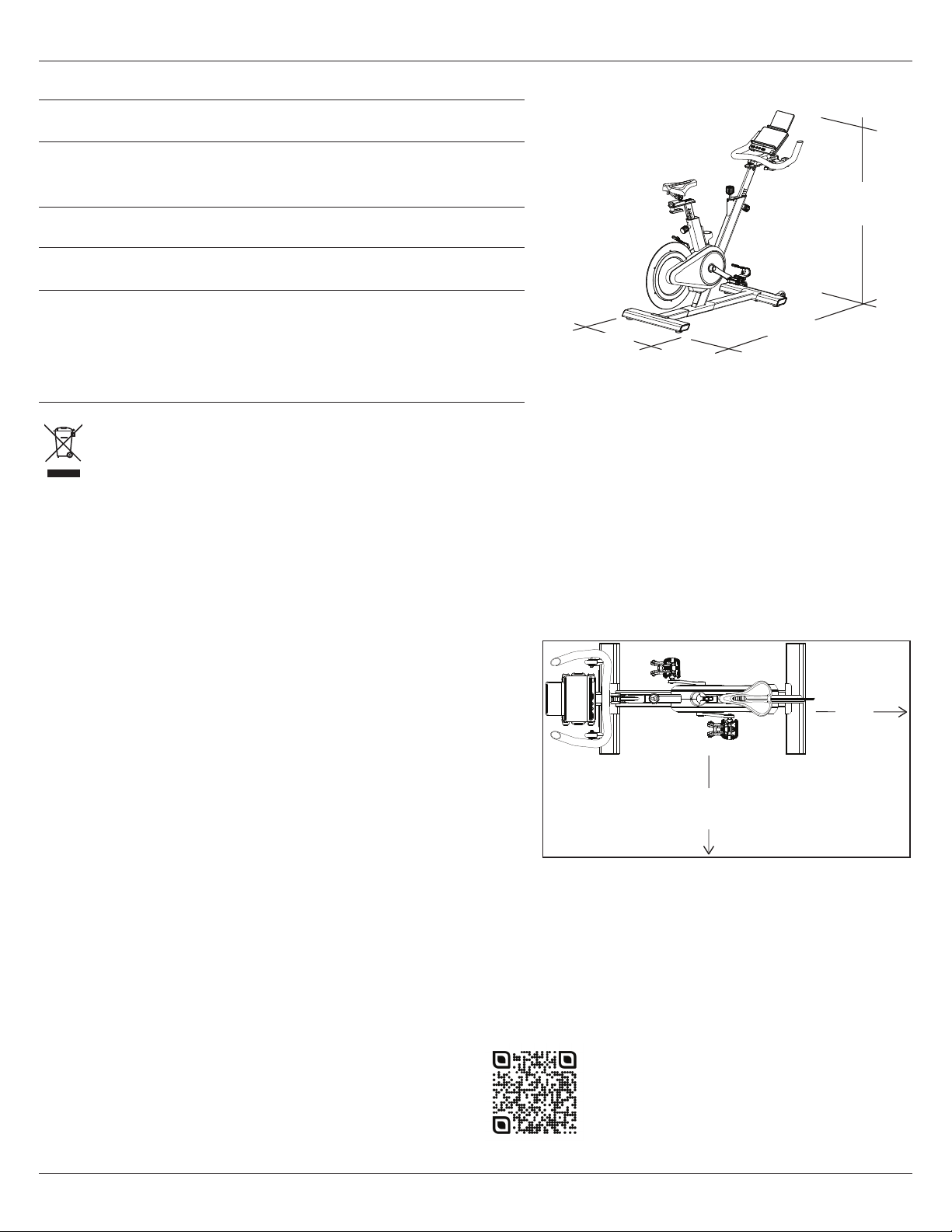
Before Assembly
Select the area where you are going to set up and operate your machine. For safe operation, the location must be on a hard, level surface.
Keep the workout area clear 0.6 m (24 in) along the side used to access the machine and to the rear of the machine. We recommend
an assembly area of 1.8 m x 2.6 m ( 71 in x 102 in ). Estimated time to assemble the machine is 45 - 50 minutes. Allow a workout area of a
minimum 1.2 m x 2 m (47 in x 79 in).
NOTICE: Inspect the machine for damaged parts due to delivery. If
damage is found, contact Customer Service (if inside US/
Canada) or your local distributor (if outside US/Canada)
for assistance.
Basic Assembly Tips
Follow these basic points when you assemble your machine:
• Read and understand the “Important Safety Instructions” before
assembly.
• Collect all the pieces necessary for each assembly step.
• Using the recommended wrenches, turn the bolts and nuts to the
right (clockwise) to tighten, and the left (counterclockwise) to
loosen, unless instructed otherwise.
• When attaching 2 pieces, carefully lift and look through the bolt
holes to help insert the bolt through the holes.
• The assembly requires 2 people.
54.5 cm
(21.5 in)
138.9 cm
(54.7 in)
134.2 cm
(52.8 in)
2 m
(79 in)
1.2 m
(47 in)
0.6 m
24 in
0.6 m
24 in
For assembly video, please visit:
www.bowflex.com/getting-started.html
10 Owner’s Manual
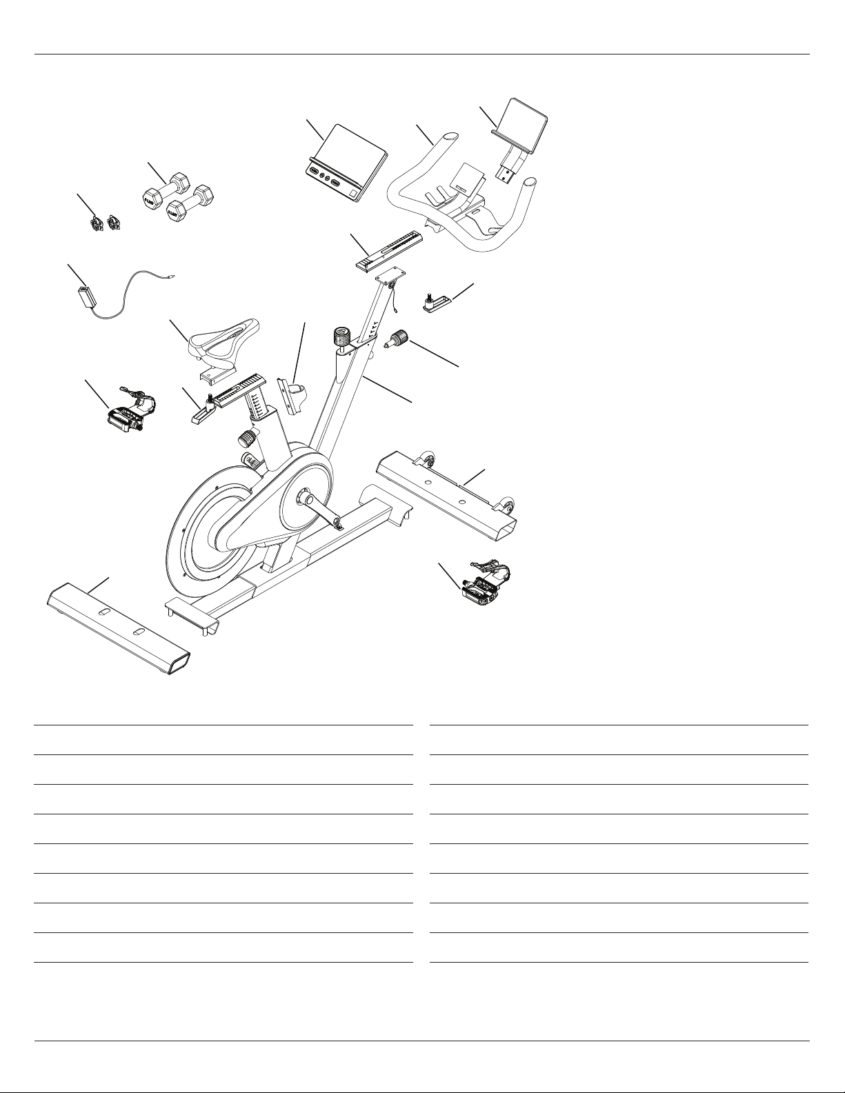
Parts, Hardware & Tools
Item Qty Description
1 1 Console
2 1 Track, Handlebar (inside Handlebar slider)
3 1 Handlebar
4 1 Media Rack
5 2 Adjustment Handle*
6 1 Adjustment Knob, Handlebar Post*
7 1 Main Assembly
8 1 Stabilizer, Front
* These items are in bag with Hardware.
Item Qty Description
9 1 Pedal, Right (R)
10 1 Stabilizer, Rear
11 1 Pedal, Left (L)
12 1 Seat
13 1 Waterbottle Holder
14 1 AC Adapter
15 2 Shoe Clips (Cleats)*
16 2 Dumbbells
1
3
4
2
5
8
7
10
9 (R)
12
11 (L)
16
15
14
5
6
13

Owner’s Manual 11
Parts, Hardware & Tools
Item Qty Description
A 4 Socket Head Cap Screw, M8 x 25 w/ pre-assembled flat washer and spring washer
B 2 Wide Washer, M10
C 4 Flathead Hex Screw, M6 x 16 w/ Threadlock
D 1 Hook and loop strap (in bag with Manual)
Note: Selected pieces of Hardware have been provided as spares in the Hardware bag. Be aware that there
may be remaining Hardware after the proper assembly of your machine.
Tools
Included
#2
6 mm
15 mm
17 mm
C
D
A B
4 mm
12 Owner’s Manual
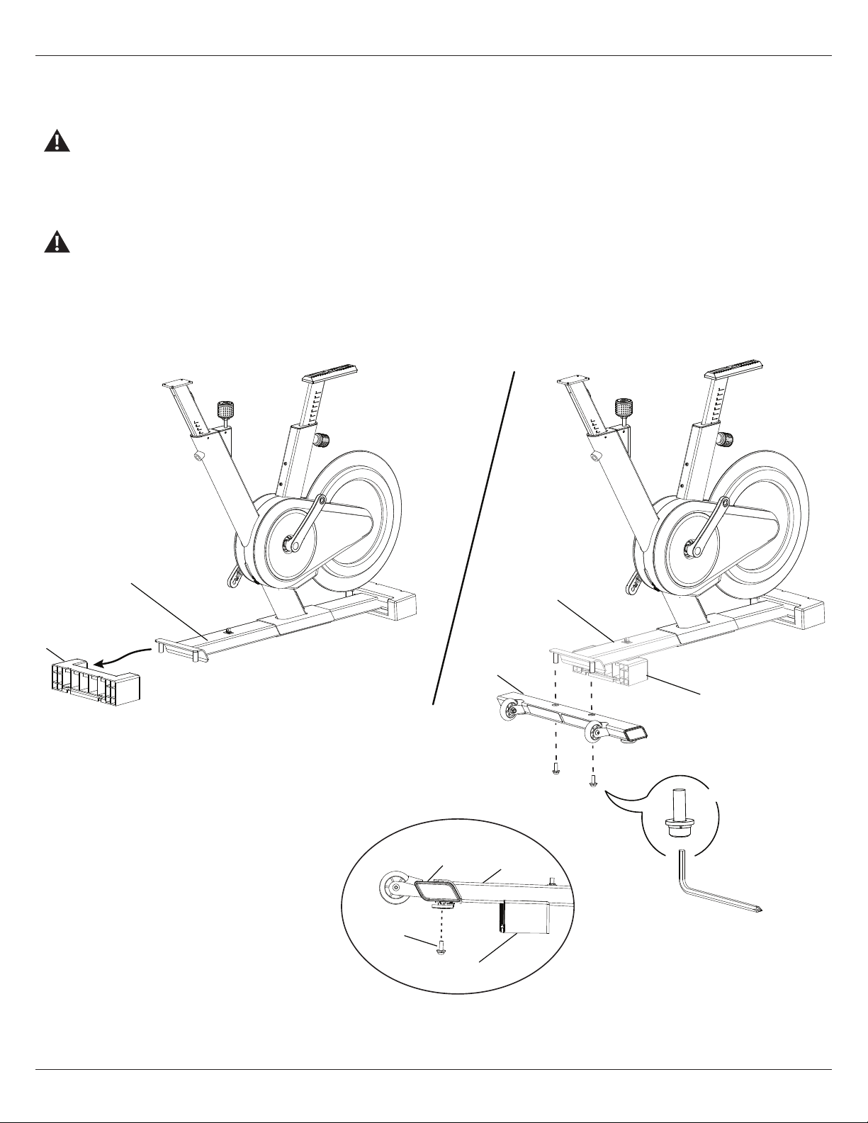
Assembly
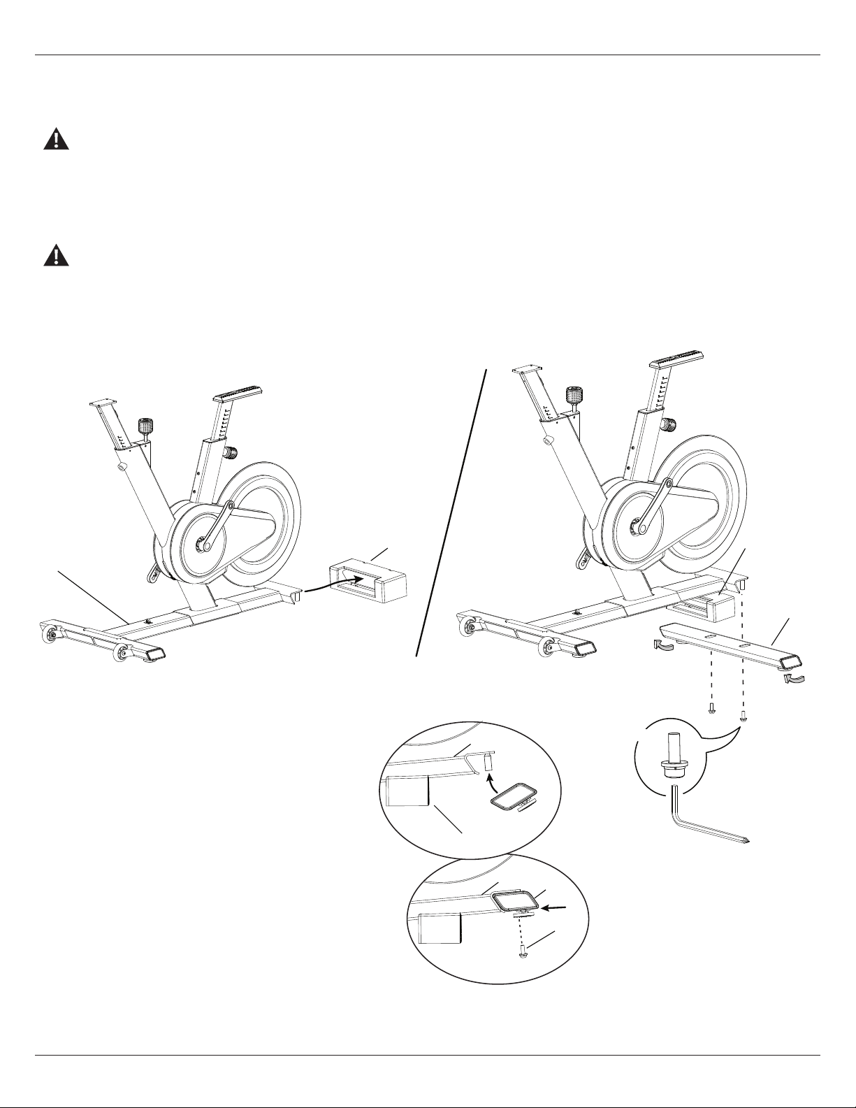
1A. Attach Front Stabilizer to Frame
Some components of the machine can be heavy or awkward. Use a second person when doing the assembly steps involving these
parts. Do not do steps that involve heavy lifting or awkward movements on your own.
Remove packaging material (P1) from Front Stabilizer bracket. Place it under the frame behind the bracket to support the front of the
machine.
Attach Front Stabilizer. Fully tighten the hardware and remove the packaging material.
Make sure the hardware is fully tightened.
8
7
P1
6 mm
A
X4
P1
8
7
A
P1
7
Front stabilizer (Left side)
Owner’s Manual 13
Assembly
1B. Attach Rear Stabilizer to Frame
Some components of the machine can be heavy or awkward. Use a second person when doing the assembly steps involving these
parts. Do not do steps that involve heavy lifting or awkward movements on your own.
Remove packaging material (P2) from Rear Stabilizer bracket. Place it under the frame in front of the bracket to support the rear of the
machine.
Pivot the Rear Stabilizer onto the mount posts in the bracket and push forward into position. Fully tighten the hardware and remove the
packaging material.
Make sure the hardware is fully tightened.
10
7
P2
6 mm
A
X4
7
10
A
P2
10
P2
7
Rear stabilizer (Left side)
14 Owner’s Manual
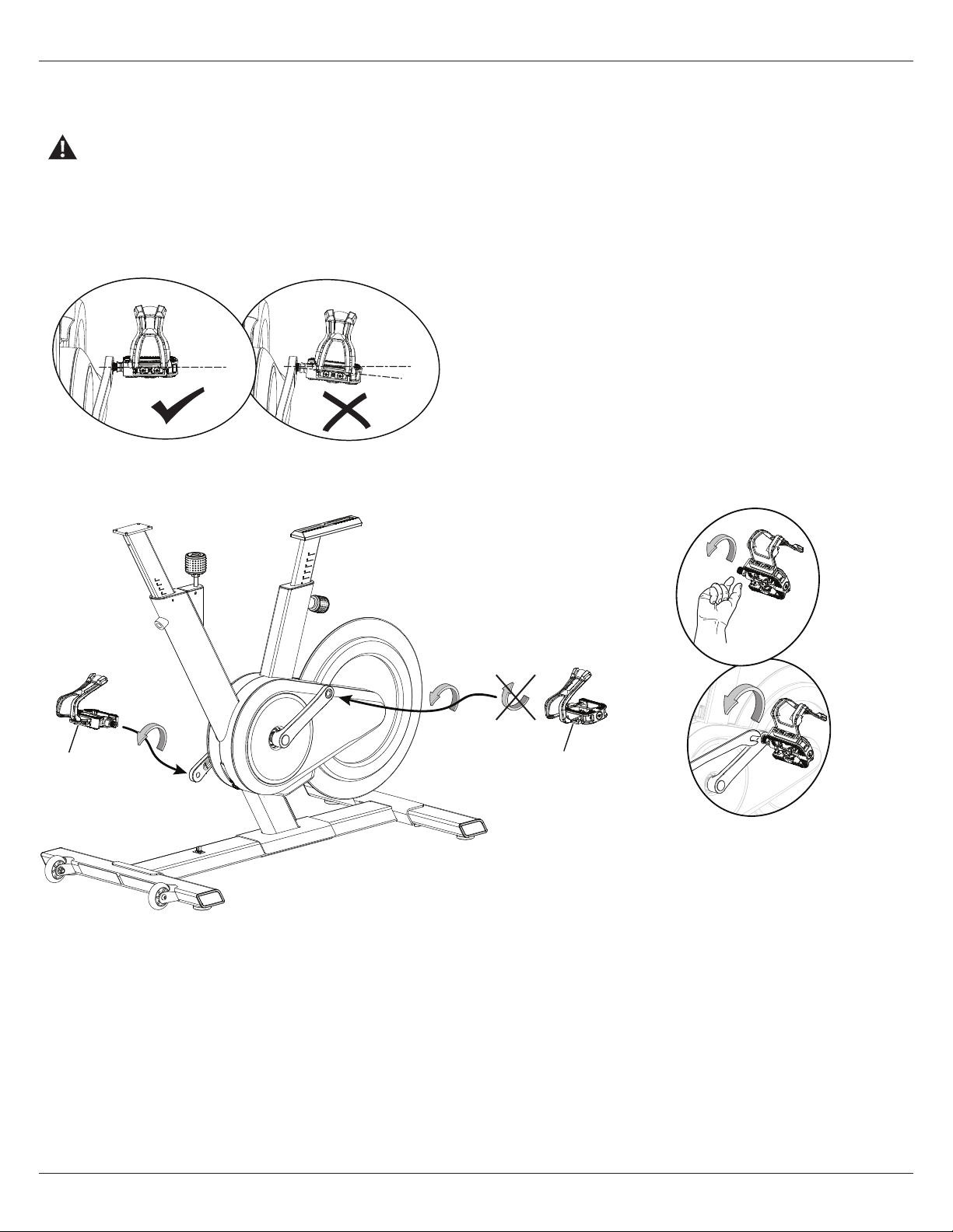
2. Attach Pedals to Frame Assembly
If the threads strip due to improper installation, then the Pedals can disengage from the bike and/or break while under usage,
which can result in serious injury to the user.
Note: The Left Pedal is reverse-threaded. Be sure to attach Pedals on the proper side of the Bike. Orientation is based from a seated
position on the bike. The Left Pedal has an “L”, the Right Pedal an “R”.
NOTICE: The Pedals MUST be installed straight into the Crank
Arms by hand or the threads that secure the Pedals may
strip. Start the Pedal by hand. If you feel resistance and
the Pedal does not turn smoothly into the Crank Arm,
make sure that the threads are aligned correctly. Be sure
that the Pedal is going on straight into the Crank Arm.
If the Pedal is not in-line with the opening, remove the
Pedal and start again.
9 (R)
11 (L)
15mm
With the Pedal started by several hand turns into the Crank Arm, fully tighten it with the 15 mm Wrench.
Confirm that the Pedal is fully tightened with the Wrench.
Repeat with the other Pedal.
Assembly
Owner’s Manual 15
Assembly
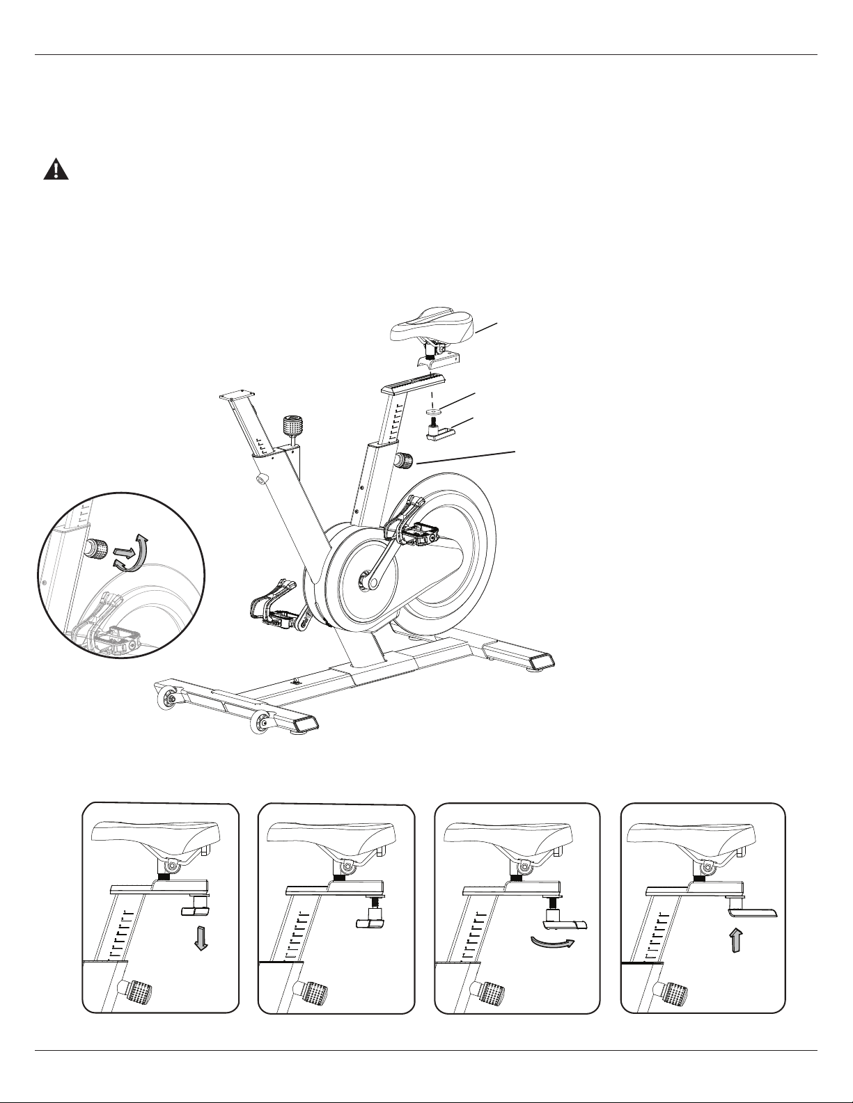
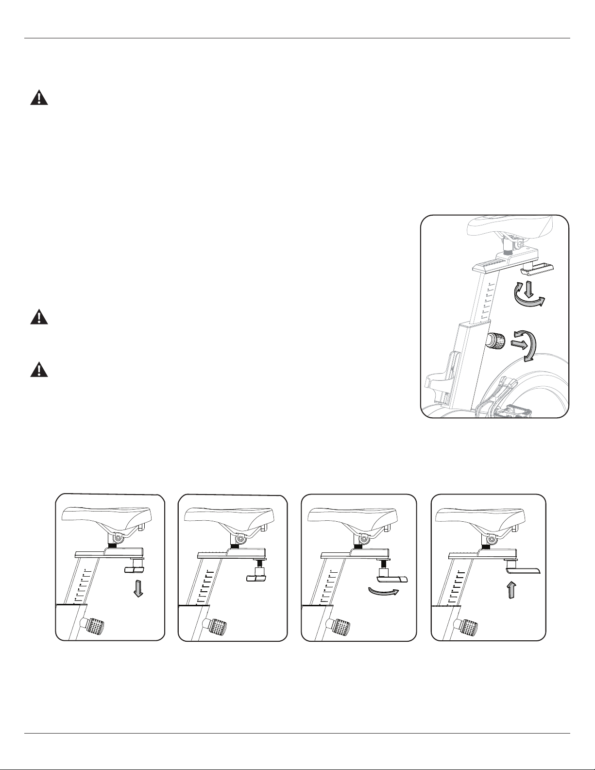
3. Install the Seat Assembly
For easier installation of the Seat, It may be helpful to adjust the Seat Post height. To adjust it, loosen the Knob and pull to disengage the
pop pin as you support the post to prevent it from dropping. Move the Seat Post to the desired position.
Do not lift the Seat Post above the “STOP” mark on the Seat Post.
Release the Adjustment Knob to lock the pop pin in the desired hole in the Seat Post. Be sure that the pin is fully engaged, then fully
tighten the Adjustment Knob.
Put the Seat assembly on the Seat Post track and install the Seat Slider Adjustment Handle (5) and wide Washer (B). Fully tighten. The
Handle should be aligned with the Seat Slider.
Note: If the handle cannot turn due to conflict with another part, pull the handle down, turn it to reposition and push it back in.
Continue turning as needed.
5
12
B
Seat Post
Adjustment Knob
16 Owner’s Manual
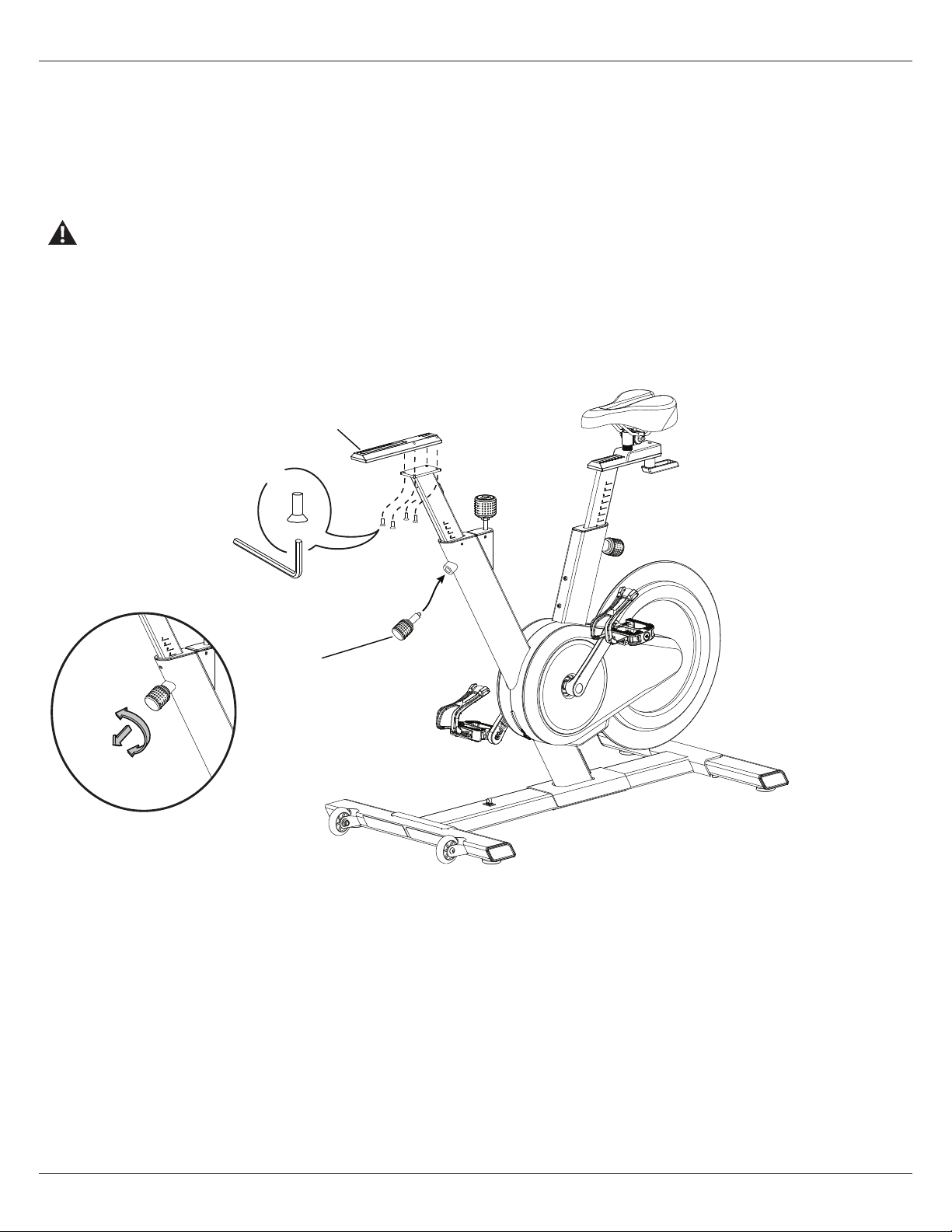
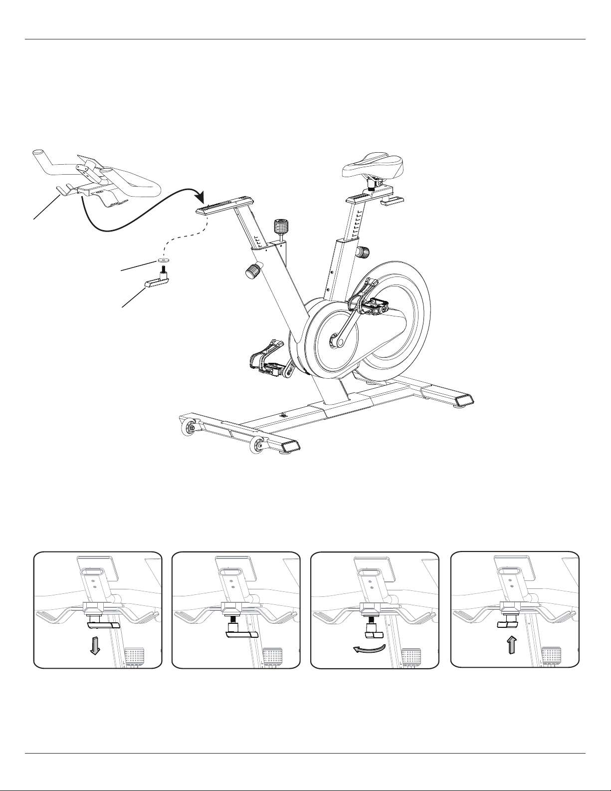
4. Attach the Handlebar Post Adjustment Knob and Handlebar Track
Tighten the Handlebar Post Adjustment Knob (6) into the mount on the Frame. For easier installation of the Handlebar Track, it may be
helpful to adjust the Handlebar Post height. To adjust it, loosen the Knob and pull to disengage the pop pin as you support the post to
prevent it from dropping. Move the Handlebar Post to the desired position.
NOTICE: Do not cut or pinch the cable.
Do not lift the Handlebar Post above the “STOP” mark on the Handlebar Post.
Release the Adjustment Knob to lock the pop pin in the desired hole in the Handlebar Post. Be sure that the pin is fully engaged,then fully
tighten the Adjustment Knob.
Align the Track on the Handlebar Post and fully tighten the screws.
2
4 mm
C
X4
6
Assembly
Owner’s Manual 17
Assembly
5. Install the Handlebar Assembly to the Frame Assembly
Put the Handlebar assembly on the Handlebar track and install the Handlebar Adjustment Handle (5) and wide Washer (B) .
Fully tighten. The handle should be aligned with the Handlebar Slider.
B
5
3
Note: If the handle cannot turn due to conflict with another part, pull the handle down, turn it to reposition and push it back in.
Continue turning as needed.
18 Owner’s Manual
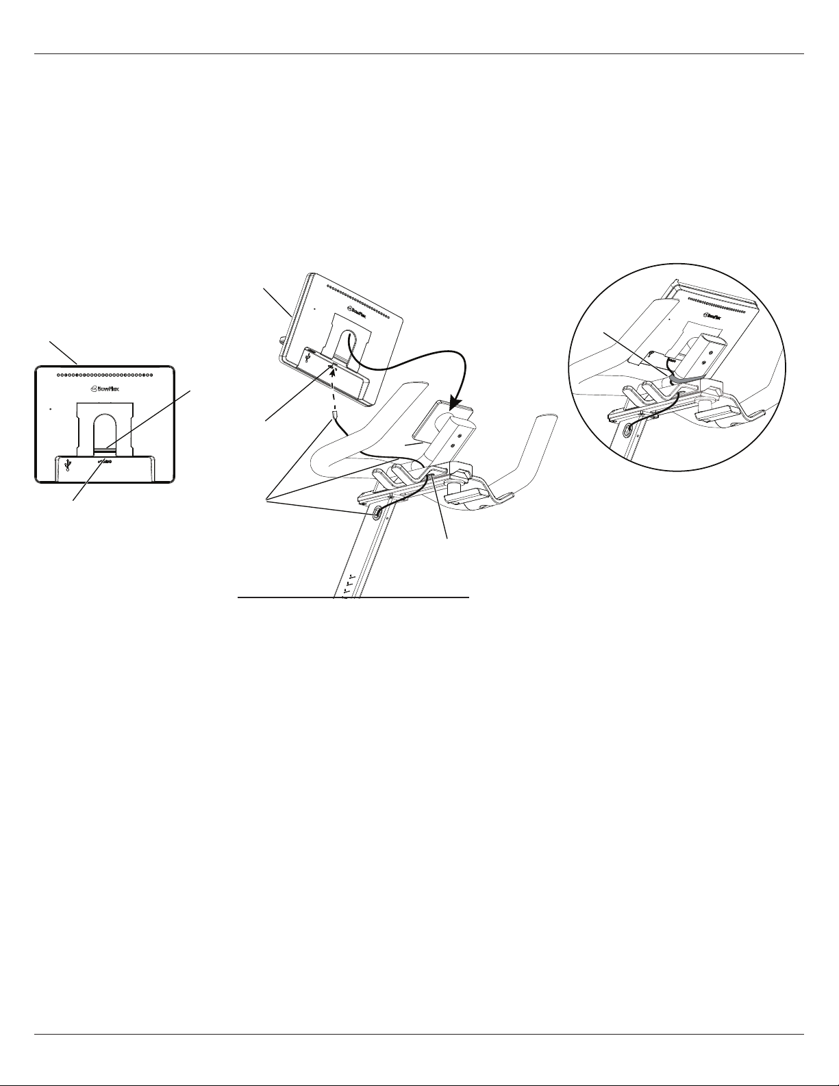
6. Install the Console to the Frame Assembly
NOTICE: Route the Data Cable (7a) through the opening (3a) to the connector (1a) on the Console before you slide the Console onto
the mount plate. If necessary, carefully pull more cable slack out of the Handlebar Post.
Make sure the wide tab (1b) on the Console engages the mount plate (3b). Carefully pull up on the Console to make sure it is
secure.
Do not cut or pinch the cable. If necessary to keep the cable out of the way, use Hook and Loop Strap (D) to secure it to the
Handlebar tube. Be sure to allow enough slack for Handlebar adjustments.
1a
1b
1
1
7a
1a
3b
3a
D
Assembly
Owner’s Manual 19
Assembly
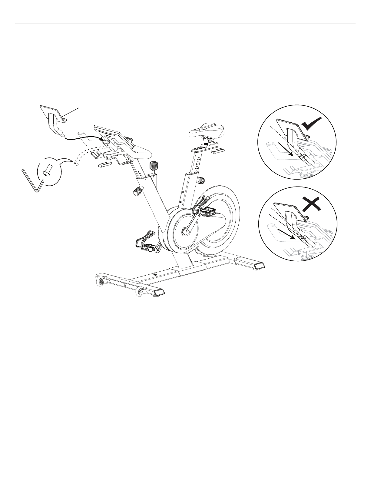
7. Attach the Media Rack to the Frame Assembly
Note: The hardware (*) is pre-installed and not in the Hardware Bag.
Insert the Media Rack tube into the Handlebar tube. As you align the holes, tilt the Media Rack slightly upward to ensure that
the outer surface of the tube is flush with the inner surface of the Handlebar tube. Make sure that the screws hold the the
Media Rack securely.
4 mm
*
X2
4
20 Owner’s Manual
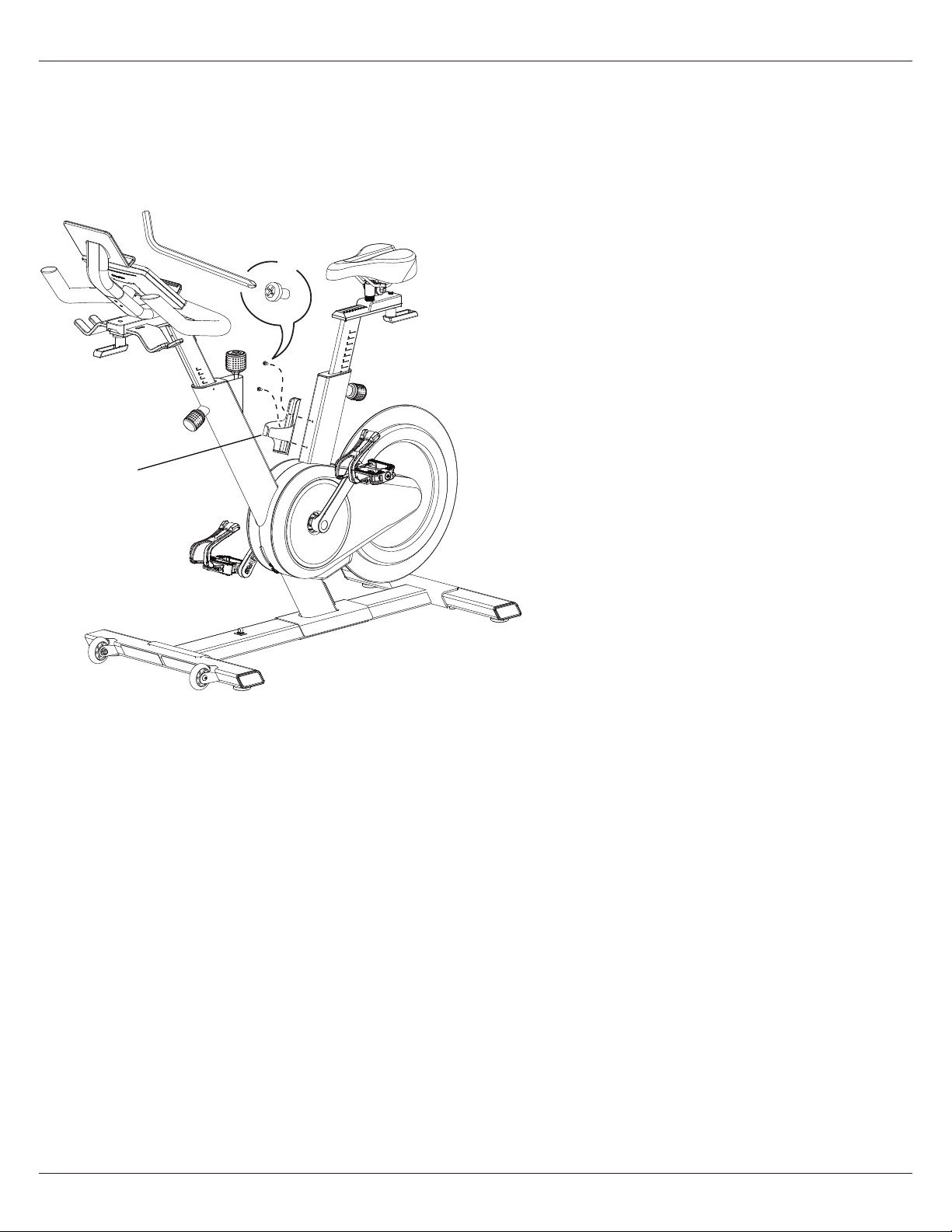
8. Attach the Waterbottle Holder
Note: The hardware (*) is pre-installed and not in the Hardware Bag.
#2
*
X2
13
Assembly
Owner’s Manual 21
Assembly
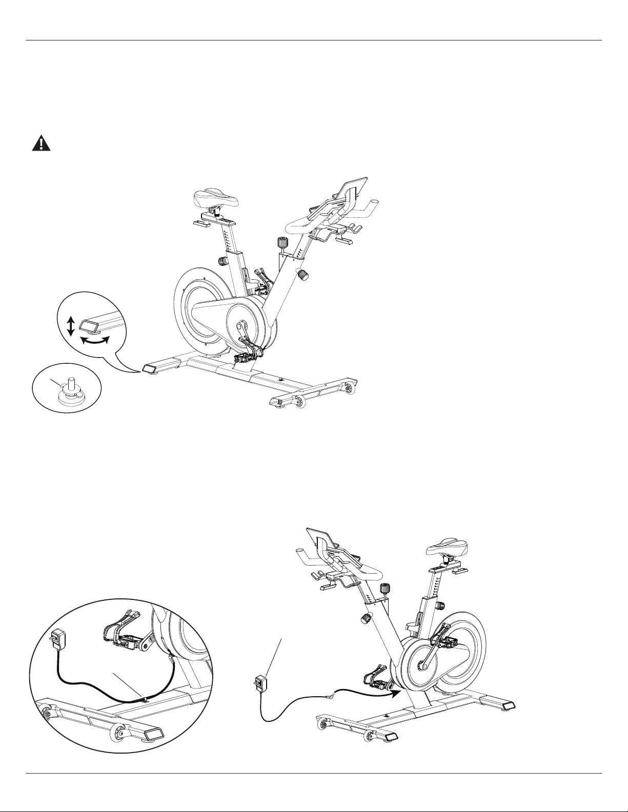
10. Connect the AC Adapter to the Frame Assembly
NOTICE: Be sure to use the appropriate AC Adapter plug for your region.
Make sure the connector is pushed all the way into the Power Inlet on the machine.
To keep the AC Adapter clear of moving parts, secure the cable in the cable guide (7b) on the Frame.
Be sure to use the appropriate AC Adapter plug for your region.
14
14
7b
9. Adjust the Levelers as Necessary
Levelers are located at each end of the Stabilizers. Loosen the locking nut (L). Turn the leveler to adjust the height. Adjust the rear levelers
until the machine is level. Tighten the locking nuts. Then adjust the front levelers to contact the floor and tighten the locking nuts. Make sure
that the machine is level.
Do not adjust the levelers to such a height that they detach or unscrew from the machine. Injury to you or damage to the
machine can occur.
L
22 Owner’s Manual
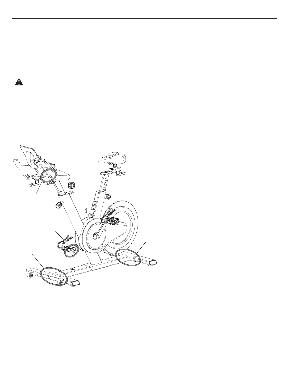
11. Final Inspection
Inspect your machine to ensure that all hardware is tight and components are properly assembled. Be sure that the Pedals are fully
tightened.
Be sure to record the serial number in the field provided at the front of this manual.
Carefully remove the protective plastic film from the display screen and keypad on the Console. Due to static electricity, “ghost” images
may show on the screen but these will disappear after a few minutes.
Do not use or put the machine into service until the machine has been fully assembled and inspected for correct performance in
accordance with the Owner’s Manual.
NOTICE: After your first few workouts, some hardware will need to be tightened again. To ensure quiet and smooth operation, make
sure to tighten the indicated hardware after three workouts. Consult the Maintenance section of this manual for recommended
future service intervals.
(X2)
Pedals
Stabilizer
Stabilizer
Assembly
Handlebar
track
Owner’s Manual 23
Assembly
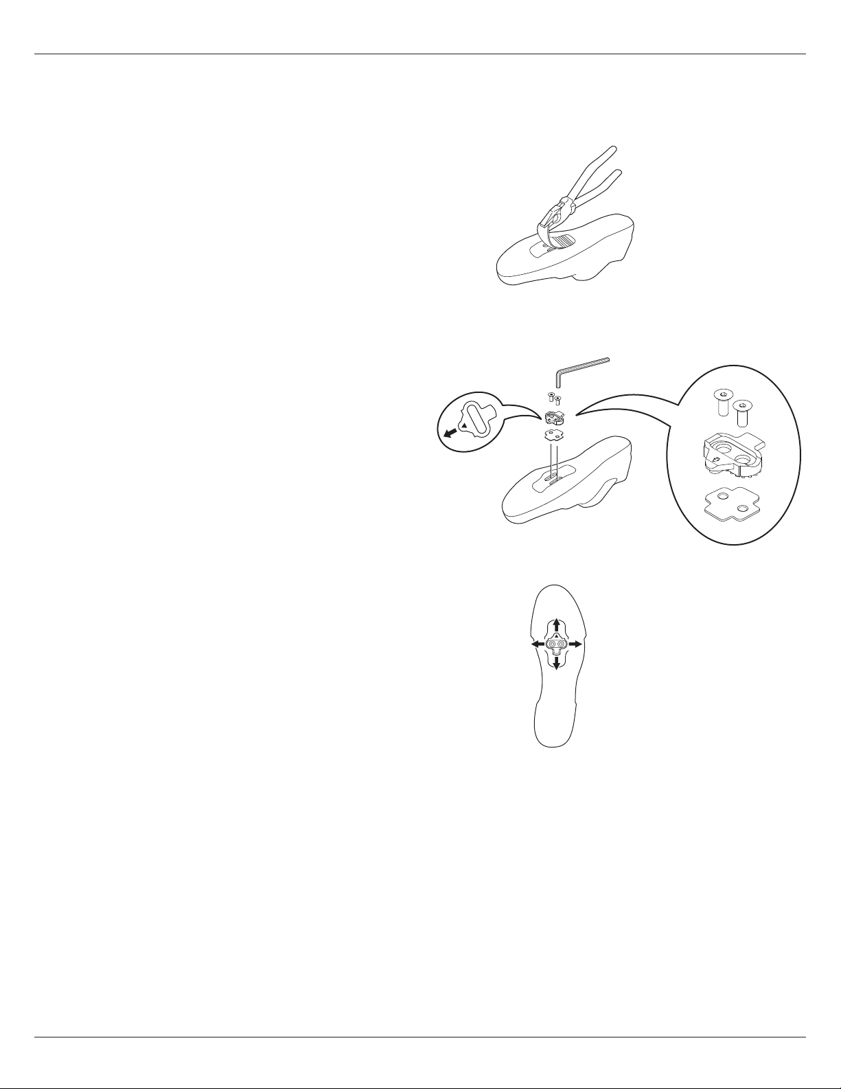
Installing the Shoe Clips (Cleats) on Cycling Shoes (Cycling Shoes not provided)
Note: The provided shoe Cleats fit both the right and left Pedals.
4 mm
Tools needed (not included): pliers, 4 mm hex wrench
1. With a pair of pliers, pull o the rubber cover to expose the cleat
mounting holes on the bottom of the cycling shoe
Note: This step may not be necessary, depending on the type
of shoe.
2. From the bottom of the shoe, put the anti-skid sheet in position
over the cleat holes and then a cleat. Be sure the single arrow on the
cleat points toward the toe of the shoe. Tighten the cleat mounting
bolts (2.5 N·m).
3. The cleat has an adjustment range of 20mm front to back and
5mm left to right. Practice engaging with the Pedal and releasing,
one shoe at a time. Readjust to determine the best cleat position.
4.
Using a 4mm hex key, fully tighten the cleat mounting bolts (5 – 6 N·m).
24 Owner’s Manual
Adjustments
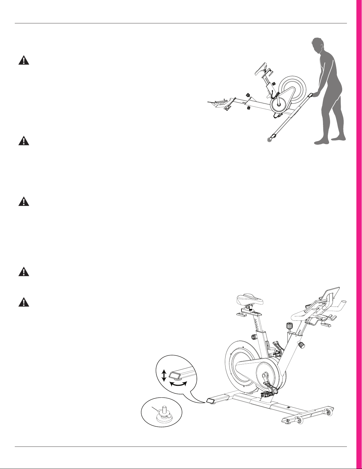
Moving the Machine
The machine may be moved by one or more persons
depending on their physical abilities and capacities. Make
sure that you and others are all physically fit and able to
move the machine safely.
1. Remove the dumbbells, any media devices, or water bottles from the
bike before moving it.
2. To lock the Flywheel, turn the Emergency Brake/Resistance
Adjustment Knob clockwise until it encounters an increase in resistance.
Then rotate the Emergency Brake/Resistance Adjustment Knob another
1/2 turn clockwise.
Tighten the Emergency Brake/Resistance Adjustment Knob as
described until the Flywheel is locked before moving it.
3. Grasp the back of the Rear Stabilizer to carefully tilt the machine forward onto the transport rollers. Push the bike to the desired
location.
Note: Be careful when you move the machine. Abrupt motions can affect the computer operation.
4. Carefully lower the machine into position.
For safe storage of the machine, remove the power supply and place in a secure location. Tighten the Brake/Resistance
Adjustment Knob as described until the Flywheel is locked. Place the machine in a secure location away from children and
pets.
Leveling the Machine
The machine needs to be leveled if your workout area is uneven. Levelers are found on each side of the stabilizers. Lift the stabilizer slightly
to take the weight o the leveler, then turn the adjustment nut (L) to adjust the stabilizer foot.
Do not adjust the levelers to such a height that they detach or unscrew from the machine. Injury to you or damage to the
machine can occur.
Tighten the locking nuts.
Make sure the machine is level and stable before
you exercise.
L

Section
Name
Owner’s Manual 25
Machine
Features
26 Owner’s Manual
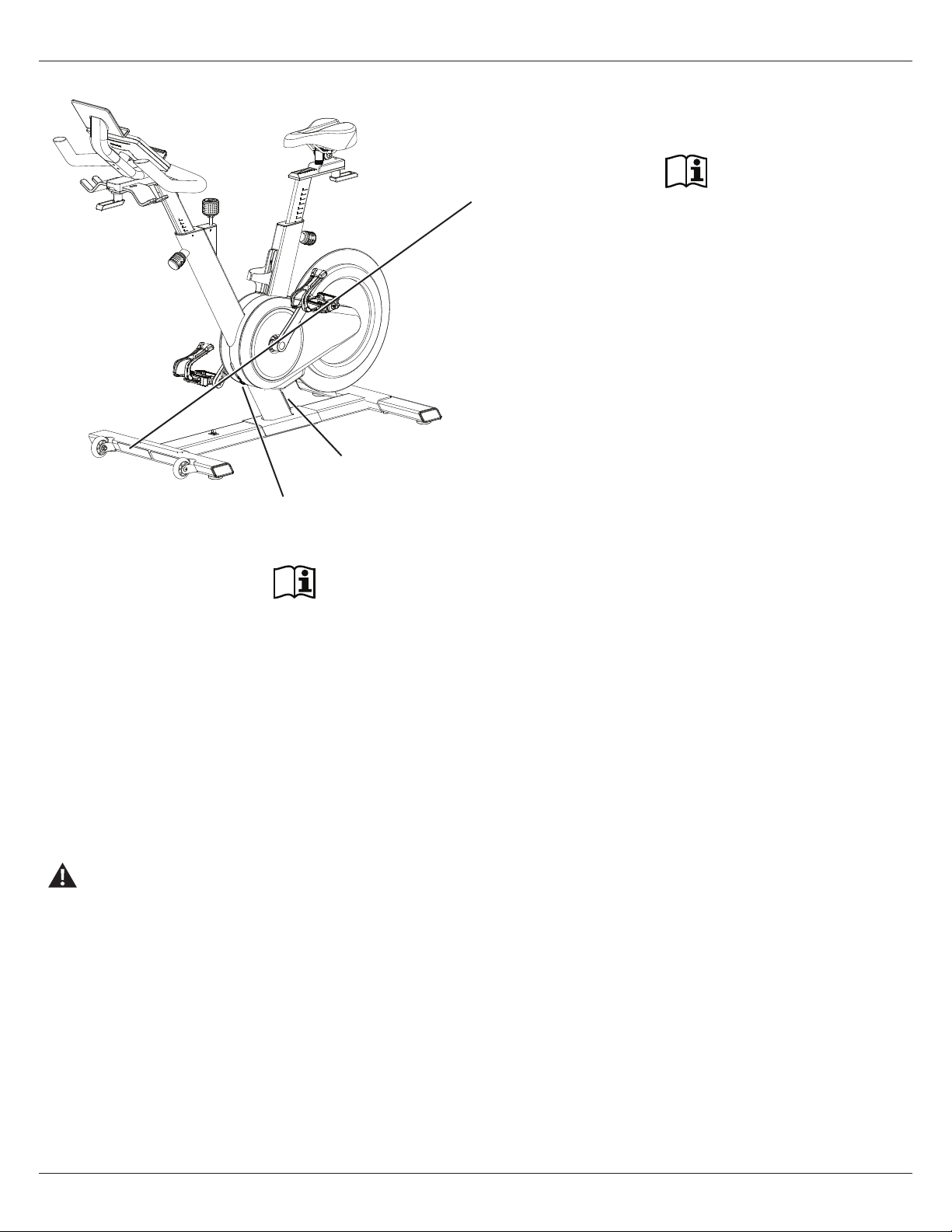
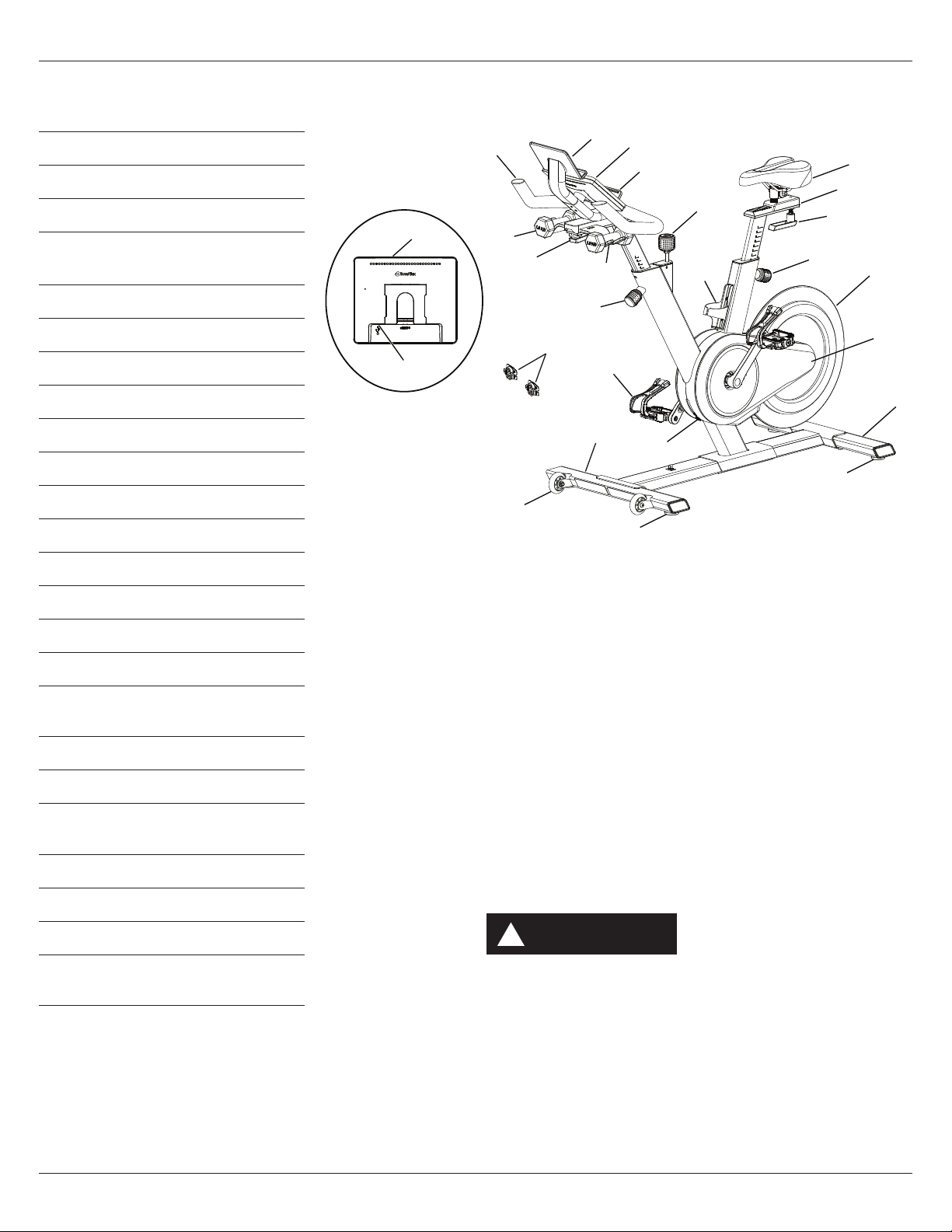
Machine Features
A Handlebar Assembly
B Media Rack
C Console
D Media Holder
E Emergency Brake/Resistance
Adjustment Knob
F Water Bottle Holder
G Seat
H Seat Slider
I Adjustment Handle, Seat Slider
J Adjustment Knob, Seat Post
K Flywheel
L Cover, Drive Belt
M Rear Stabilizer
N Leveler
O Transport Wheel
P Front Stabilizer
Q Power Inlet
R Pedal w/Foot Restraint and Shoe
Cleat
S Adjustment Knob, Handlebar Post
T Dumbbell Rack
U Adjustment Handle, Handlebar
Slider
V Dumbells
W Shoe Clips (Cleats)
X USB Charging Port
Y Bluetooth® Connectivity (not
shown)
Z Bluetooth® Heart Rate (HR)
Receiver (not shown)
Use the values calculated or measured by the machine’s
computer for reference purposes only. The heart rate
displayed is an approximation and should be used for
reference only. Over exercising may result in serious injury
or death. If you feel faint stop exercising immediately.
WARNING
!
A
K
M
W
X
B
B
C
D
E
F
G
H
J
L
N
N
O
P
Q
R
S
T
U
I
V
Owner’s Manual 27
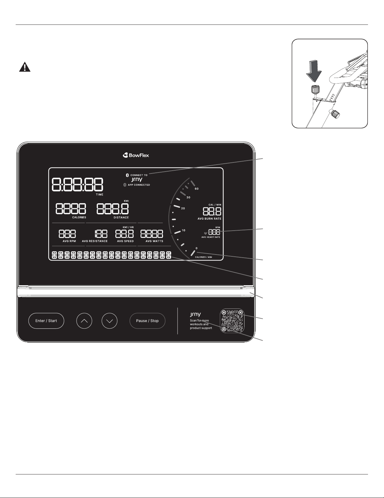
Console
Emergency Stop
To stop the pedals immediately, push down hard on the Emergency Brake/Resistance Adjustment Knob.
This bike cannot stop the Pedals independently of the Flywheel. Reduce the pace to slow the
Flywheel and Pedals to a stop. Do not dismount the bike until the Pedals have come to a
complete stop. Be aware that the moving Pedals can strike the backs of the legs.
Heart Rate Detected icon
JRNY / App Connected icons
Message display
Media Holder
Tachometer
Console Features
The Console provides information about your workout on the display
screens.
Keypad Functions
Enter/Start button
Starts a workout, confirms the workout values, and moves forward
through menu options.
Increase () button
Push to move through available settings options.
Decrease () button
Push to move through available settings options.
Pause/Stop button
Pauses an active workout or ends a paused workout.
Reset button (centered in text)
For service technician use only. When pushed during power up, the
button restores the Console settings to the factory default state.
The Console will require updates to be applied in order to become
fully functional. Workout data is not aected.
JRNY QR code
Reset button
28 Owner’s Manual
JRNY™ App
JRNY QR code
To look for more workouts and product information, scan the QR
code with your device.
The console will sound a tone when a button is pushed (if the
Volume setting is on).
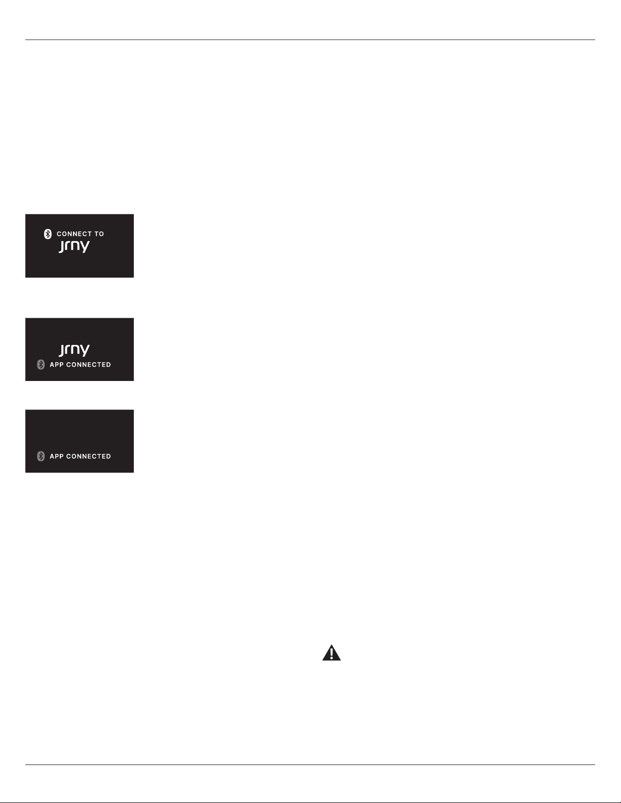
Workout Data Display
White Bluetooth® logo +
“CONNECT TO” + JRNY™
icon
Display shows before, during and after
a Manual workout if the machine is not
connected to the JRNY™ app.
Blue Bluetooth® logo +
JRNY™ icon + “APP
CONNECTED”
Display shows during a workout with a
personal device using the JRNY™ app.
Blue Bluetooth® logo +
“APP CONNECTED”
Display shows during a workout with a
personal device using an App other than
the JRNY™ app.
TIME
The TIME display field shows the time from start to finish of
workout. During the workout, the display counts up from zero.
The maximum time is 9 hours 59 minutes and 59 seconds.
CALORIES
The CALORIES display field shows estimated calories that you have
burned during the exercise. The maximum calories value is 9999
Kcal.
DISTANCE
The DISTANCE display field shows the distance count (KM or MI) in
the workout.. The distance counts up from 0 (zero). The maximum
distance value is 999.9.
Note: The default distance unit is miles (MI). To switch units
between kilometers and miles before a workout, push the Enter/
Start button and hold for 3 seconds to enter the Console Setup
Mode. The System Units prompt appears.. Push an Increase/De-
crease button to change the units (KM or MI). With the desired
unit of distance displayed, push the Pause/Stop button to save.
RPM
The RPM display field shows the pedal speed in revolutions per
minute (RPM).
RESISTANCE
The RESISTANCE display field shows the current resistance level.
The range of resistance is 0% - 100%, which can be modified by
increments of 1.
SPEED
The SPEED display field shows the currently calculated speed of
the user in miles per hour (MI/HR) or kilometers per hour (KM/HR).
The maximum SPEED is 99.9 (KM or MI) / HR.
Message Display
The Message Display field shows program notifications, prompts
and answers.
Tachometer
The Tachometer shows the current Burn Rate (calories per minute)
of the user.
BURN RATE
The BURN RATE display field shows the level of calories being
burned per minute. This rate is a function of intensity, which is the
current level of RPM (pedal speed) and resistance level. As either of
those values increase, the Burn Rate will increase.
Heart Rate Detected icon
Display shows when the Console is paired with a Bluetooth® Heart
Rate Monitor.
HEART RATE
The HEART RATE display shows the beats per minute (BPM) from a
Bluetooth® Heart Rate Monitor. When a heart rate signal is received
by the Console, the icon will flash. If no heart rate is detected, the
display will not be displayed.
Consult a physician before you start an exercise program.
Stop exercising if you feel pain or tightness in your chest,
become short of breath, or feel faint. Contact your doctor
before you use the machine again. Use the values
calculated or measured by the machine’s computer for
reference purposes only. The heart rate displayed on the console is
an approximation and should be used for reference only.
Owner’s Manual 29
JRNY™ App, Charging and Bluetooth® Heart Rate
Connect your device with the JRNY™ app for
more dynamic workouts
If you have a JRNY™ membership*, it can be accessed through your
device when synced to the console of this Bowflex™ machine. With
that JRNY™ membership, you receive guided workouts adapted
to your capabilities, conveniently displayed on your device, and
friendly virtual voice coaching designed to support you on your
journey to long-term fitness success.
1. Download the app, named “BowFlex™ JRNY™”. The app is available
on the App Store and Google Play™.
2. Be sure that the Bluetooth® and Location Settings are active on
your device. Activate them if necessary.
3. Open the app near the machine, and follow the instructions to
sync your device to the machine.
If the app will not sync to the machine, restart your device and the
machine. Repeat Step 3.
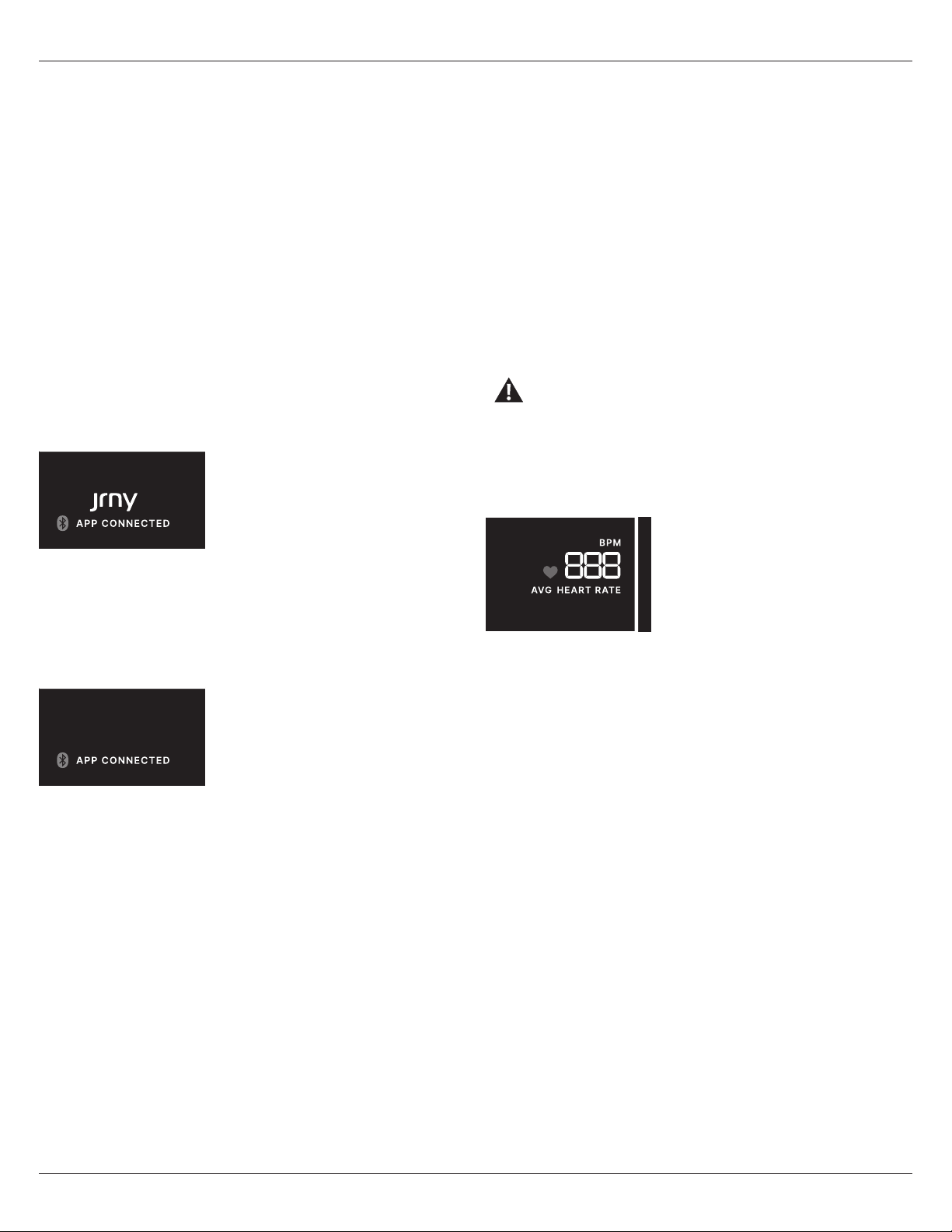
When connected, the Console will
display the blue Bluetooth® logo +
JRNY™ icon + “APP CONNECTED”
displays.
Workout with Other Apps
This fitness machine has integrated Bluetooth® connectivity which
allows it to work with a number of third party apps. For our latest
list of compatible apps, please visit: www.bowflex.com/apps
When connected with a non-JRNY™
app, the Console will display the blue
Bluetooth® logo + “APP CONNECTED”
displays.
USB Charging
If a USB Device is attached to the USB Port, the Port will attempt to
charge the Device. The power supplied from the USB Port may not
be enough to operate the Device and charge it at the same time.
NOTICE: Do not connect a USB Device to the Power/Data Port on
the Console.
Bluetooth® Heart Rate Strap (not supplied)
Your fitness machine is equipped to be able to receive a signal from
a Bluetooth® Heart Rate Strap. When connected, the Console will
display the Bluetooth® Heart Rate Detected icon.
If you have a pacemaker or other implanted electronic
device, consult your doctor before using a Bluetooth®
strap or other Bluetooth® heart rate monitor.
1. Put on your Bluetooth® Heart Rate Strap.
2. If equipped, push the On/O button on your strap to activate it.
The Console actively searches for any devices in the area, and
should connect to the strap when in range.
The Bluetooth® Heart Rate Detected
icon will activate when connected. You
are ready to work out.
At the end of your workout, push
the On/O button (if equipped) to
disconnect your Heart Rate Strap
from the Console.
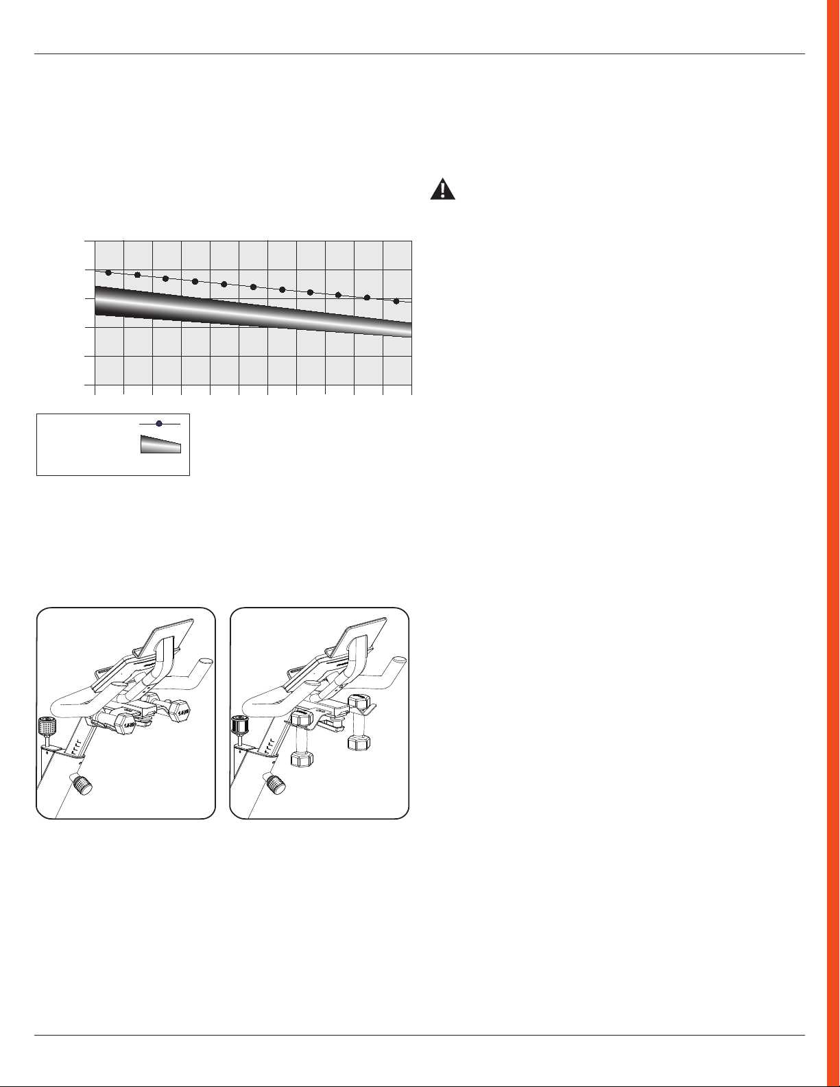
Heart Rate Calculations
Your maximum heart rate usually decreases from 220 Beats Per
Minute (BPM) in childhood to approximately 160 BPM by age 60.
This fall in heart rate is usually linear, decreasing by approximately
one BPM for each year. There is no indication that training
influences the decrease in maximum heart rate. Individuals of the
same age could have dierent maximum heart rates. It is more
accurate to find this value by completing a stress test than by using
an age related formula.
Your at-rest heart rate is influenced by endurance training. The
typical adult has an at-rest heart rate of approximately 72 BPM,
whereas highly trained runners may have readings of 40 BPM or
lower.
The Heart Rate table is an estimate of what Heart Rate Zone (HRZ)
is eective to burn fat and improve your cardiovascular system.
Physical conditions vary, therefore your individual HRZ could be
several beats higher or lower than what is shown.
The most eicient procedure to burn fat during exercise is to start
at a slow pace and gradually increase your intensity until your
heart rate reaches between 60 – 85% of your maximum heart rate.
Continue at that pace, keeping your heart rate in that target zone
for over 20 minutes. The longer you maintain your target heart rate,
the more fat your body will burn.
*A JRNY™ membership is required for the JRNY™ experience –
see www.bowflex.com/jrny for details. For United States and
Canada customers, you can obtain a JRNY™ membership by calling
800-269-4126 or visiting www.bowflex.com/jrny. Where avail-
able (including the United States), you can also obtain a JRNY™
membership by downloading the JRNY™ app onto your phone or
tablet and signing up within the downloaded app. JRNY™ member-
ships may not be available in all countries.
30 Owner’s Manual
Heart Rate Calculations
Shoe Clips (Cleats)
Foot pedals that are equipped for cycling shoes with cleats
provide secure footing on the exercise bike. The shoe cleats
provided fit both the right and left Pedals.
Prior to use, make sure you understand the operation of the
engagement / release mechanism for the pedals and cleats
(shoes).
Keep cleats and bindings clear of dirt and debris to ensure
engagement and release.
Check the cleats periodically for wear. When the cleats are
worn, replace them. Replace the cleat when it becomes
diicult to release, or starts to release with much less
eort than when it was in new condition.
Pedals and cleats are SPD Compatible. They fit any shoe size
with the correct cleat mounts: shoes with “Standard 2-Hole MTB
SPD Cleat Mounts” (MTB SPD = Mountain Bike Shimano Pedaling
Dynamics).
The graph is a brief guideline, describing the generally suggested
target heart rates based on age. As noted above, your optimal
target rate may be higher or lower. Consult your physician for your
individual target heart rate zone.
Note: As with all exercises and fitness regimens, always use your
best judgment when you increase your exercise time or intensity.
20-24
FAT-BURNING TARGET HEART RATE
Heart Rate BPM (beats per minute)
Age
25-29
0
50
100
150
200
250
30-34 35-39 40-44 45-49 50-54 55-59 60-64 65-69 70+
196
191
186
181
176
171
166
161
156
151
146
167
162
158
154
150
145
141
137
133
128
126
Maximum Heart Rate
Target Heart Rate Zone
(keep within this range
for optimum fat-burning)
11 8
11 5
11 2
109
106
103
100
97
94
91
88
FAT-BURNING
ANAEROBIC
AEROBIC
Dumbbell Rack – Dual Position
The Dumbbell Rack on the Handlebar provides convenient storage
for the Dumbbells in a horizontal or upright position.

Section
Name
Owner’s Manual 31
Operations
32 Owner’s Manual
How Often Should You Exercise
Consult a physician before you start an exercise program. Stop exercising if you feel pain or tightness in your chest, become
short of breath, or feel faint. Contact your doctor before you use the machine again. Use the values calculated or measured
by the machine’s computer for reference purposes only. The heart rate displayed on the console is an approximation and
should be used for reference only.
• 3 times a week for about 20 minutes each day.
• Schedule workouts in advance and try to follow the schedule
Note: If you are new to exercise (or returning to a regular exercise program), and you are unable to comfortably complete 20 minutes of
continuous exercise at one time, just do 5 – 10 minutes, and gradually increase your workout time until you can reach a 20 minute total.
Seat Adjustment
Correct seat placement encourages exercise eiciency and comfort, while reducing the risk of
injury.
1. With a Pedal in the forward position, place the heel of your foot to the lowest part of it. Your leg
should be bent slightly at the knee.
2. If your leg is too straight or your foot cannot touch the Pedal, you need to move the seat
downward. If your leg is bent too much, you need to move the seat upward.
Step o the machine before you adjust the seat.
3. Loosen and pull the Seat Post Adjustment Knob on the Seat Post to disengage the pop pin as you
hold the post to prevent it from dropping. Adjust the Seat to the desired height.
Do not lift the Seat Post above the “STOP” mark on the Seat Post.
4. Release the Seat Post Adjustment Knob to lock the pop pin in the desired hole in the Seat Post.
Be sure that the pin is fully engaged and fully tighten the adjustment knob.
5. To move the seat closer to, or away from the console, loosen the Seat Slider Adjustment Handle.
Slide the seat to the desired position and fully tighten the handle. Pull the handle down and turn
so that it is aligned with the Seat Slider, then release.
Note: If the handle cannot turn due to conflict with another part, pull the handle, turn and push it back in to reposition it. Continue
turning as needed.
Operations
Owner’s Manual 33
Operations
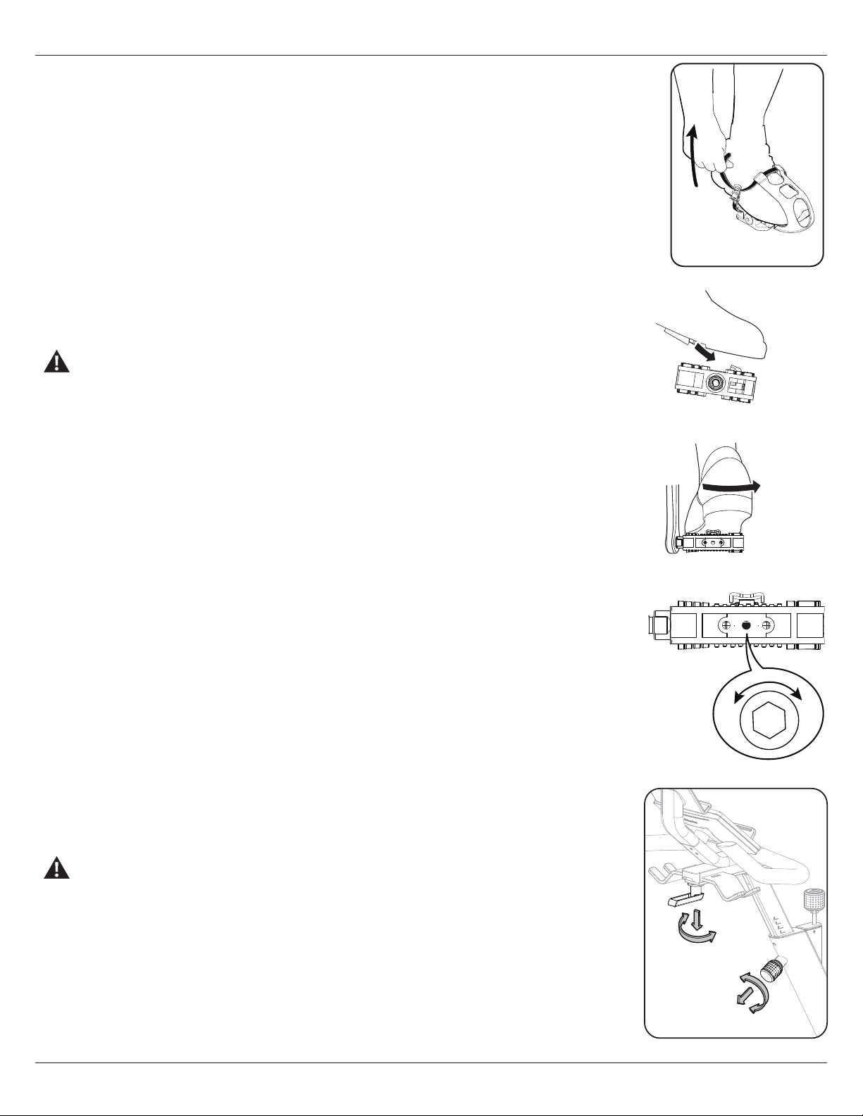
Foot Position / Pedal Strap Adjustment
Foot pedals with straps provide secure footing to the exercise bike.
1. Put the ball of each foot in the Foot Restraint on the Pedals.
2. Fasten the strap over the shoe.
3. Repeat for the other foot..
Be sure toes and knees point directly forward to ensure maximum Pedal eiciency. Pedal straps can be
left in position for subsequent workouts.
Using the Shoe Clips (Cleats)
Foot pedals that are equipped for cycling shoes with cleats provide secure footing on the exercise bike.
Be sure to turn the Pedals so that the Foot Restraint is under the Pedal.
Prior to use, make sure you understand the operation of the engagement / release mechanism for
the pedals and cleats (shoes).
1. Be sure that the arrow on top of the Pedal points forward.
2. Push the cleat down and forward to engage the Pedal..
3. Repeat for the other foot.
4. Practice engaging and disengaging from the Pedals before starting your workout.
To disengage (release) the cleats from the pedals, push the heels outward and lift.
If the body weight of a user is very low, the user may have diiculty with operation of the engagement/
release mechanism in the Pedals. It may be necessary to decrease the retention force of the mechanism.
To adjust the retention:
1. Locate the opening in the rear of the Pedal for access to the adjustment bolt. It is between the 2 screws
that attach the Foot Restraint to the Pedal.
2. Use a 3mm hex wrench to turn the adjustment bolt. To decrease the retention, turn it left
(counterclockwise). To increase the retention, turn it right (clockwise).
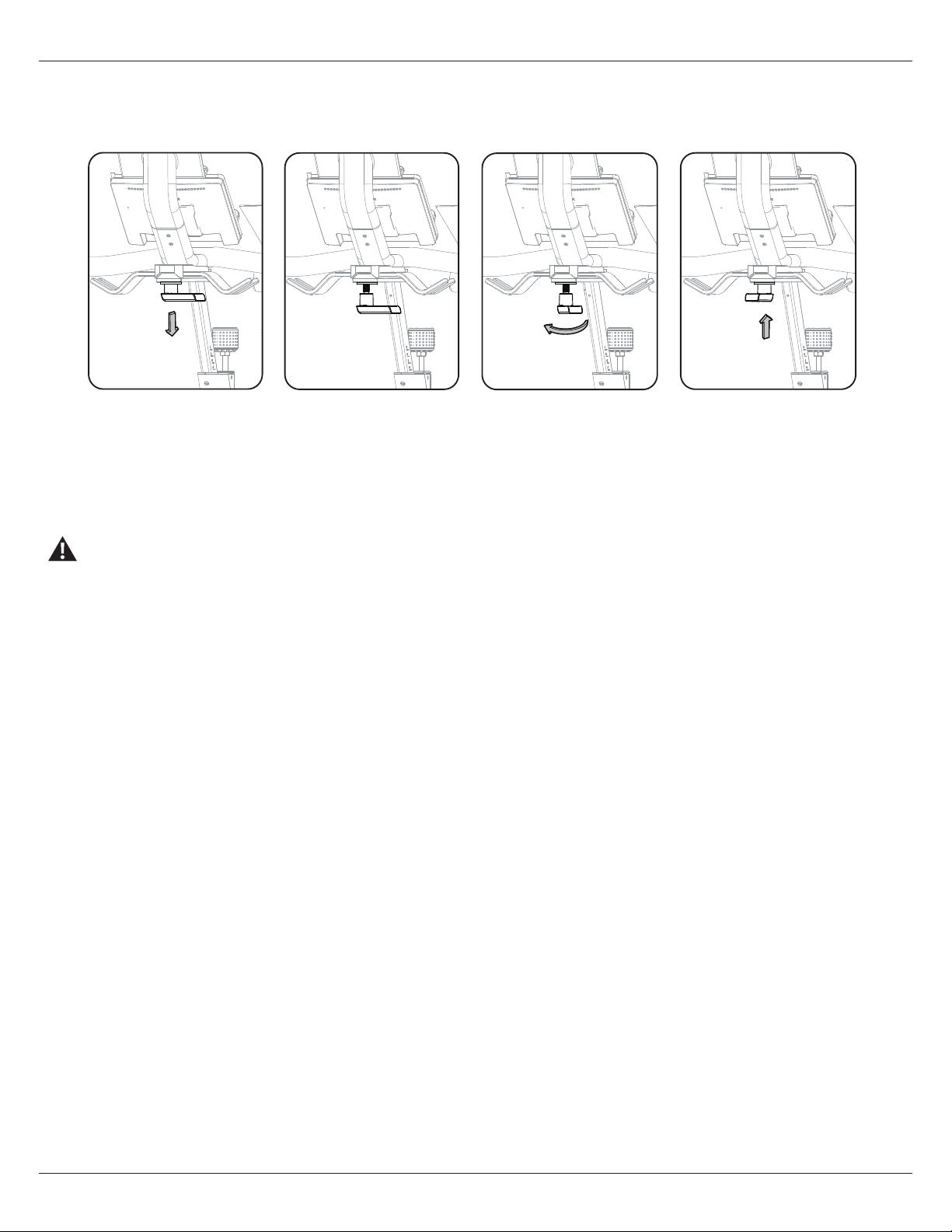
Handlebar Adjustment
To adjust the handlebar position:
1. Loosen and pull the Handlebar Post Adjustment Knob on the Handlebar Post to disengage the pop pin
as you hold the post to prevent it from dropping. Adjust the Handlebar to the desired height.
Do not lift the Handlebar Post above the “STOP” mark on the Handlebar Post.
2. Release the Handlebar Post Adjustment Knob to lock the pop pin in the desired hole in the Handlebar
Post. Be sure that the pin is fully engaged and fully tighten the adjustment knob.
NOTICE: Do not cut or pinch the cables.
3. To move the Handlebar closer to, or away from the seat, loosen the Handlebar Slider Adjustment
Handle. Slide the Handlebar to the desired position and fully tighten the handle. Pull the handle down and
turn so that it is aligned with the Handlebar Track, then release.
Engage
Disengage (release)
-
+
34 Owner’s Manual
Note: If the handle cannot turn due to conflict with another part, pull the handle, turn and push it back in to reposition it. Continue
turning as needed.
Locking the Flywheel for Storage
When the machine is not in use, be sure to lock the Flywheel with the Emergency Brake/Resistance Adjustment Knob. To lock the Flywheel,
turn the Emergency Brake/Resistance Adjustment Knob clockwise until it encounters an increase in resistance. Then rotate the Emergency
Brake/Resistance Adjustment Knob another 1/2 turn clockwise. The Flywheel is now locked. The flywheel should be locked for storage of
the machine.
For safe storage of the machine, remove the power supply and place in a secure location. Tighten the Brake/Resistance
Adjustment Knob as described until the Flywheel is locked. Place the machine in a secure location away from children and
pets.
With the Flywheel locked, the level of resistance will be out of the range of operation displayed by the Console. Do not use the machine
with the level of resistance outside of the 0% - 100% range. This will damage the ability to quickly stop the Flywheel during an emergency,
and the eectiveness of securing the bike for storage. Turn the Emergency Brake/Resistance Adjustment Knob until the RESISTANCE
displayed on the Console is less than 100%. The resistance is now in the designed range of operation for the bike. .
Power Up Mode
The Console will enter Power-Up mode if any button is pushed, or if it receives a signal from the RPM sensor as a result of pedaling the
machine.
Auto Shut-O (Sleep Mode)
If the Console does not receive any input in approximately 5 minutes, it will automatically shut o. The LED display is o while in Sleep
Mode.
Note: The Console does not have an On/Off switch.
Resistance Adjustment
To increase the resistance and workload, turn the resistance adjustment knob clockwise. To reduce the resistance, turn the
resistance adjustment knob counter-clockwise. The range of movement of the Resistance Adjustment Knob is 0% to slightly
past the 100% level of resistance (locked Flywheel). Do not turn the Resistance Adjustment Knob past the range of movement.
If turned past the range of movement, damage to the machine may occur.
Starting a Manual Workout
1. Resistance shows the current resistance level. Heart Rate (if connected) shows the current reading (BPM). All other data values are zero.
2. Push the Enter/Start button and start pedaling.
3. The Workout will begin.
Console Operation

Owner’s Manual 35
Console Operation
Changing Unit Measures (English Imperial/Metric)
To switch units between kilometers and miles before a workout, push the Enter/Start button and hold for 3 seconds to enter the Console
Setup Mode. The System Units prompt appears. Push an Increase/Decrease button to change the units (KM or MI). With the desired unit
of distance displayed, push the Pause/Stop button to save.
Note: The default distance unit is MI.
Pausing or Stopping a Workout
1. To pause your workout, tap the Pause/Stop button one time. While paused, the Console will display “Workout Paused”.
2. To continue your workout, tap the Enter/Start button one time.
The workout will end after being paused for 5 minutes.
When paused, the Console display will display the current workout values for the workout. To end the paused workout, tap the Pause/
Stop button.
Muting the Console
The Console has the option to be muted. It does not aect the output from your personal device.
1. Push and hold for 3 seconds the Enter/Start button to enter the Console Setup Mode. The System Units prompt appears.
2. Push the Enter/Start button twice. The Volume prompt will appear with the current volume setting.
3. Push the Decrease button until MUTE is displayed as the Volume setting.
4. With the desired volume setting displayed, push the Pause/Stop button to save. The Console will display “Settings Saved” for 2 seconds,
and then exit the Console Setup Mode.
Note: The default volume setting is Medium.
Workout Summary
After a workout, the Console display will show “Workout Complete”. The Console will show the Workout Summary values for 5 minutes.
Note: The workout must be longer than 1 minute in order for the JRNY™ app to store the data. The data is not stored in the Console.
The summary includes total and average workout values. The total workout values are Time, Calories and Distance. The average workout
values are RPM, Resistance, Speed, Burn Rate and Heart Rate (if available).
Note: If no Heart Rate was provided during the workout, the Console will not report a value.
The Workout Summary will end after 5 minutes or if the Pause/Stop button is pushed.

36 Owner’s Manual
Console Setup Mode – System Menu
The Console Setup Mode allows you to set units of measurement to either Imperial or metric, adjust screen brightness, view
maintenance statistics (such as Run Time hours and software version – for service technician use only), or reset the Console.
1. Push the Enter/Start button and hold for 3 seconds while in the Power-Up Mode to go into the Console Setup Mode (System Menu).
Note: Push the Pause/Stop button to save and exit the System Menu and return to the Power-Up Mode screen. The Console will
display "Settings Saved" before exiting to the System Menu.
2. The Console display shows the System Units prompt with the current setting. The default setting is Imperial English units. Push the
Increase/Decrease buttons to change between Imperial (MI/LB) and metric (KM/KG).
Note: If the units change when there is data in User Statistics, the statistics convert to the new units.
3. Push the Enter/Start button to set the selection and continue to the next menu option.
Note: To save the selection and exit the System Menu, push the Pause/Stop button.
4. The Console display shows the Screen Brightness prompt with the current setting. The levels of brightness are: 5 (100%), 4 (80%,
default), 3 (65%), 2 (50%), 1 (35%). The display shows the brightness of the selected level. Push the Increase/Decrease buttons to
move to the desired level.
5. Push the Enter/Start button to set the selection and continue to the next menu option.
6. The Console display shows the Volume prompt with the current setting for the Console beeps. The volume levels are: O, Low,
Medium (default), High. Push the Increase/Decrease buttons to move to the desired level. It does not aect the output from your
personal device.
7. Push the Enter/Start button to set the selection and continue to the next menu option.
8. The Console display shows the Disconnect Bluetooth prompt. The default option is NO. The YES option will disconnect all Bluetooth®
devices. Push the Increase/Decrease buttons to change between options (YES/NO).
9. Push the Enter/Start button to set the selection and continue to the next menu option.
10. The Console display shows the Auto Connect HR (Heart Rate) prompt. The default option is YES. Push the Increase/Decrease
buttons to change between options (YES/NO).
11. Push the Enter/Start button to set the selection and continue to the next menu option.
12. The Console display shows the Display Metrics prompt. The default option is YES. Push the Increase/Decrease buttons to enable/
disable the display of metrics when connected to the JRNY™ app.
13. Push the Enter/Start button to continue to the next menu option.
14. The Console display shows the Hardware Variant & Console Firmware Version.
15. Push the Enter/Start button to continue to the next menu option.
16. The Console display shows the Base Serial Number.
17. Push the Enter/Start button to continue to the next menu option.
18. The Console display shows the Hardware Variant (machine type).
19. Push the Enter/Start button to set the selection and continue to the next menu option.
20. The Console display shows the Run Time hours (total number of hours of workout time).
21. Push the Enter/Start button to continue to the next menu option.
22. The Console display shows the BLE Version.
23. Push the Enter/Start button to continue to the next menu option.
24. The Console display shows the EX SNSR Version.
25. Push the Enter/Start button to continue to the next menu option.
26. The Console display shows the Error Log prompt (for service technician use only). Push the Decrease button to see the saved errors.
At the end of the errors, the Console display shows the Clear Errors prompt. Push PAUSE/STOP to clear the log. If cleared, the
Console will exit the Console Setup Mode.
27. Push the Enter/Start button to continue to the next menu option.
Console Setup Mode

Owner’s Manual 37
Console Setup Mode
28. The Console display shows the Reset Console prompt. The default option is NO. Push the Pause/Stop button to exit without starting
Reset.
Note: The YES option will reset the System Units, Screen Brightness and Demo Mode to default settings. It does not reset the Run Time
Hours.
Push the Increase/Decrease buttons to change between options (YES/NO).
Push the Enter/Start button to go back to the System Units prompt ( first System Menu option).
Push the Pause/Stop button to set the selection and exit the System Menu.
29. The Console will display the Power-Up Mode screen.

38 Owner’s Manual
Read all maintenance instructions fully before you start any repair work. In some conditions, an assistant is required to do the necessary tasks.
Equipment must be regularly examined for damage and repairs. The owner is responsible to make sure that regular maintenance is
done. Worn or damaged components must be repaired or replaced immediately. Only manufacturer supplied components can be
used to maintain and repair the equipment.
If at any time the Warning labels become loose, unreadable or dislodged, replace the labels. If purchased in US/Canada, contact
Customer Service for replacement labels. If purchased outside US/Canada, contact your local distributor for them.
Disconnect all power to the machine before you service it.
Daily
Before each use, examine the exercise machine for loose, broken, damaged, or worn parts. Do not use if found
in this condition. Repair or replace all parts at the first sign of wear or damage. Make sure adjustment knobs
are tight. Tighten as necessary. After each workout, use a damp cloth to wipe your machine and Console free of
moisture.
Note: If necessary, only use a mild dish soap with a soft cloth to clean the Console. Do not clean with a petro-
leum based solvent, automotive cleaner, or any product that contains ammonia. Do not clean the Console in
direct sunlight or at high temperatures. Be sure to keep the Console free of moisture.
Weekly
Check pedals and tighten as necessary.
Clean the machine to remove any dust, dirt, or grime from the surfaces.
Check for smooth seat operation. If needed, sparingly apply a thin coating of silicone lube to ease operation.
Silicone lubricant is not intended for human consumption. Keep out of reach of children.
Store in a safe place.
Note: Do not use petroleum based products.
Monthly
(Or after 20 hours)
Check crank arms and tighten as necessary. Make sure all bolts and screws are tight. Tighten as necessary.
Check the drive belt tension and adjust if necessary.
When the machine is used in a Studio/Institutional environment, we recommend that the Pedals be replaced every year to maintain
maximum user safety and performance. Only use replacement Pedals available from BowFlex. Other brands of Pedals may not be
designed for this product, and can cause danger to users and bystanders, and will void the warranty.
Checking the Drive Belt Tension
To check the Drive Belt tension, the bike needs to be operated. Get the pedals rotating at about 20 RPM. Then suddenly increase the
RPM to your maximum ability. If the pedals move normally with no slipping, the tension is correct. If the Pedals slip, the belt needs to be
adjusted.
The “Adjust the Belt Tension” procedure can be found in the Service Manual.
Maintenance
Owner’s Manual 39
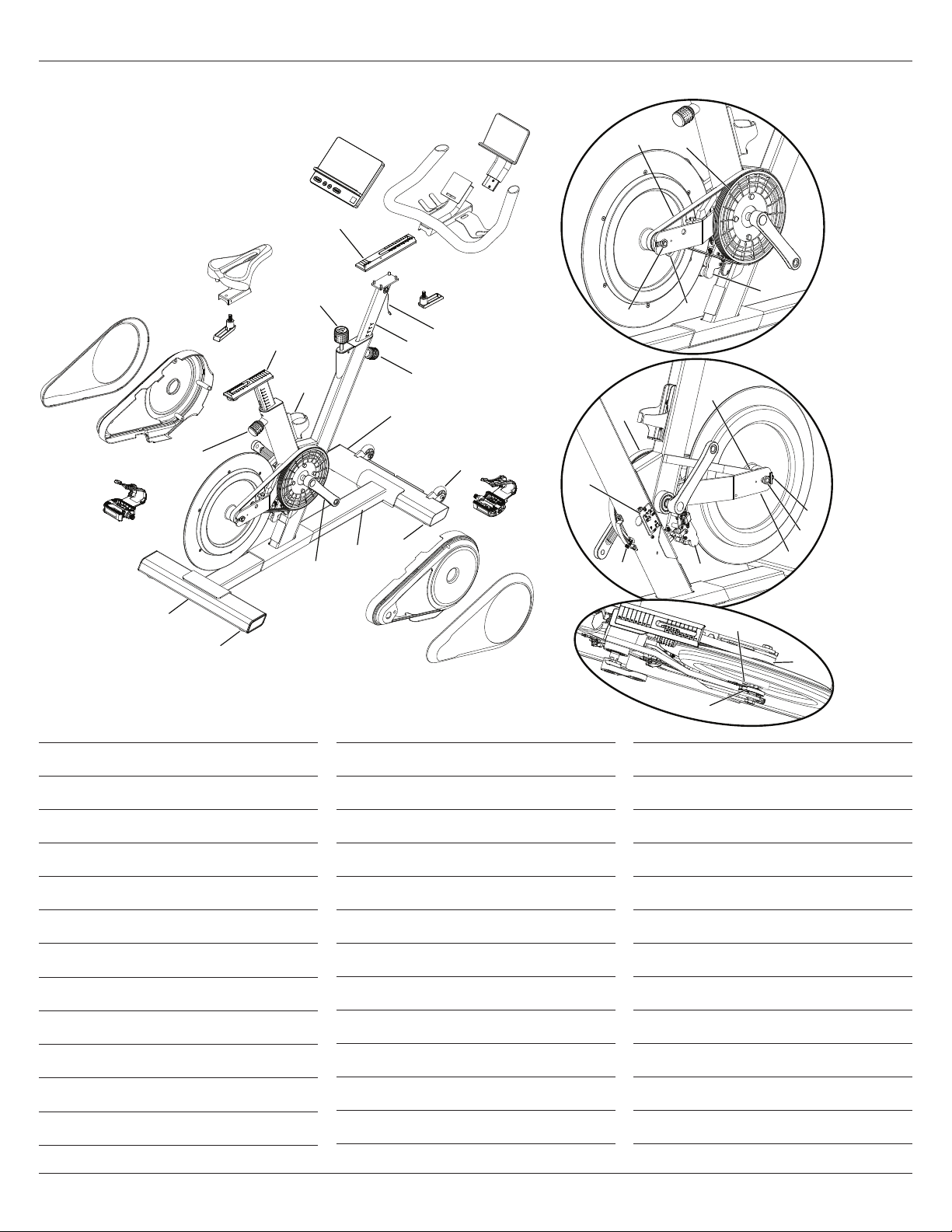
Maintenance
A Console Assembly
B Track, Handlebar
C Handlebar Assembly
D Media Rack
E Adjustment Handle
F Data Cable
G Handlebar Post
H Handlebar Post Adjustment Knob
I Front Stabilizer
J Transport Wheel
K Pedal w/Foot Restraint, Right
L Shroud, Structural, Right
M Outside Shroud, Right
N Leveler
O Frame Assembly
P Crank Arm
Q Rear Stabilizer
R Pedal w/Foot Restraint, Left
S Seat Post Adjustment Knob
T Outside Shroud, Left
U Shroud, Structural, Left
V Seat Assembly
W Seat Post
X Water Bottle Holder
Y Brake/Resistance Knob
Z Flywheel
AA Drive Belt
BB Drive Pulley
CC Resistance Shoe
DD Idler Assembly (Belt Tensioner)
EE Axle Nut
FF Speed Sensor
GG Flywheel Retainer Nut
HH Speed Sensor Magnet
II Power Inlet
JJ PCBA, Base Hub
A
B
C
D
E
F
H
K
L
M
J
I
N
N
Q
P
U
T
R
E
Y
V
W
X
S
G
P
Z
Z
AA
AA
BB
CC
CC
DD
EE
FF
GG
HH
II
JJ
FF
HH
AA
O
P
EE

40 Owner’s Manual
Condition/Problem Things to Check Solution
No display/unit will not
turn on
Console in sleep mode Push any Console button or move pedals to wake up Console.
AC Adapter Check for visual sign that AC Adapter is cracked or otherwise
damaged. Replace AC Adapter if damaged.
Check electrical (wall) outlet Make sure unit is plugged into a functioning wall outlet.
Check connection at front
of unit
Connection should be secure and undamaged. Unplug connector
and inspect inlet for any damage. Plug connector back into inlet.
Check Status LED in back of
Console
If Status LED is:
- on (solid), then the Console is starting up. May take up to 3
minutes. (Status LED is o when Console is operating.)
- blinking , then console software is updating.
Check data cable
connections/orientation
Be sure cable is connected securely and oriented properly. Small
latch on connector should line up and snap into place.
Check data cable integrity All wires in cable should be intact. If any are visibly cut or pinched,
replace cable.
Check console display
for damage
Check for visual sign that console display is cracked or otherwise
damaged. Replace Console if damaged.
If the above steps do not resolve the problem, contact Customer
Service (if inside US/Canada) or your local distributor (if outside
US/Canada).
Troubleshooting

Owner’s Manual 41
Troubleshooting
Condition/Problem Things to Check Solution
Speed displayed is not
accurate
Check Speed Sensor Magnet
position
Speed Sensor Magnet should be in place on Flywheel.
Speed displayed is always
“0”
Data cable Make sure the data cable is connected to the Console from the
main frame assembly.
Speed Sensor Make sure the data cable is connected to the Speed Sensor.
No Speed/RPM reading Check data cable integrity All wires in cable should be intact. If any are cut or pinched,
replace cable.
Check data cable
connections/orientation
Be sure cable is connected securely and oriented properly. Small
latch on connector should line up and snap into place.
Check Speed Sensor Assembly Speed Sensor Assembly should be connected to data cable.
Realign sensor if necessary. Replace if there is any damage to the
sensor or the connecting wire.
Resistance does not change
when Resistance Knob is
rotated during workout
Check data cable integrity All wires in cable should be intact. If any are visibly cut or pinched,
replace cable.
Check data cable
connections/orientation
Be sure cable is connected securely and oriented properly. Small
latch on connector should line up and snap into place.
Check Console display
for damage
Check for visual sign that console display is cracked or otherwise
damaged. Replace Console if damaged.
If the above steps do not resolve the problem, contact Customer
Service (if inside US/Canada) or your local distributor (if outside
US/Canada).
Console displays “Base
Connect Error”
Data cable Make sure the data cable connection to the Console is firmly
seated.

42 Owner’s Manual
Condition/Problem Things to Check Solution
Unit operates but
Bluetooth® Heart Rate
(HR) not displayed
Bluetooth® Heart Rate sensing
device
Fully charge HR device and activate. Be sure any protective
cover has been removed from HR sensors. Make sure sensors are
directly against skin and contact area is wet.
Heart Rate sensing device
Batteries
If HR device has replaceable batteries, install new batteries.
Interference Try moving unit away from sources of interference (TV,
Microwave, etc).
Replace HR device If interference is eliminated and HR does not function, replace HR
device.
If the above steps do not resolve the problem, contact Customer
Service (if inside US/Canada) or your local distributor (if outside
US/Canada).
Console shuts o (enters
sleep mode) while in use
Check electrical (wall) outlet Make sure unit is plugged into a functioning wall outlet.
Check connection at front of
unit
Connection should be secure and undamaged. Replace adapter or
connection at unit if either are damaged.
Check data cable integrity All wires in the cable should be intact. If any are cut or pinched,
replace cable.
Check data cable
connections/orientation
Be sure cable is connected securely and oriented properly. Small
latch on connector should line up and snap into place.
Reset machine Unplug unit from electrical outlet for 5 minutes. Reconnect to
outlet.
Check Speed Sensor Speed sensor should be aligned with magnet and connected to
data cable. Realign sensor if necessary. Replace if there is any
damage to the sensor or the connecting wire.
If the above steps do not resolve the problem, contact Customer
Service (if inside US/Canada) or your local distributor (if outside
US/Canada).
Troubleshooting

Owner’s Manual 43
Troubleshooting
Condition/Problem Things to Check Solution
Unit rocks/does not
sit level
Check leveler adjustment Adjust levelers until machine is level.
Check surface under unit Adjustment may not be able to compensate for extremely uneven
surfaces. Move machine to level area.
Pedals loose/unit diicult
to pedal/ Pedals seem to
skip or slip with a sudden
increase in RPM
Check pedal to crank
connection
Pedal should be tightened securely to crank arm. Be sure
connection is not cross-threaded.
Check crank arm to axle
connection
Crank arm should be tightened securely to axle.
Check drive belt tension Refer to the “Adjust the Belt Tension” procedure. Contact
Customer Service (if inside US/Canada) or your local distributor
(if outside US/Canada).
Clicking sound when
pedaling
Check pedal to crank
connection
Remove pedals. Make sure there is no debris on threads, and
reinstall the pedals.
Seat post movement Check adjustment knob pin Be sure adjustment pin is locked into one of the seat post
adjustment holes.
Check locking knob Be sure knob is securely tightened.
Console continuously
displays a video of machine
features
Console is in demonstration
mode
Press and hold the hidden button beside the JRNY QR code on the
Console for 3 seconds. The hidden button is centered in the text to
the left of the QR code. The setting will take eect after the next
time the machine goes into Sleep Mode.
Console displays an update
prompt
Console Allow the Console updates to run. The screen may go dark
during the update process. Do not turn the power o or leave
the machine unattended. Once the updates are completed and
the Power-Up Mode screen is displayed, the machine may be
powered o.

Section
Name
44 Owner’s Manual
Warranty

Owner’s Manual 45
Warranty
Who Is Covered
This warranty is valid only to the original purchaser and is not
transferable or applicable to any other person(s).
What Is Covered
BowFlex Inc. warrants that this product is free from defects in
materials and workmanship, when used for the purpose intended,
under normal conditions, and provided it receives proper care and
maintenance as described in the Product’s Assembly and Owner’s
manual. This warranty is good only for authentic, original, legitimate
machines manufactured by BowFlex Inc. and sold through an
authorized agent and used in the United States or Canada.
Terms
Warranty terms for products purchased in US/Canada are as
stated below.
Frame 10 years
Parts 2 years
Electronics 1 year
Labor 1 year
(Labor support does not include the installation of replacement
parts involved in the initial product assembly and preventative
maintenance services. All repairs covered under the labor portion
of the warranty must be preauthorized by BowFlex. The customer
will be responsible for a minimal trip charge.)
For warranty & service of products purchased outside US/
Canada, please contact your local distributor. To find your local
international distributor, go to:
global.bowflex.com
How BowFlex Will Support the Warranty
Throughout the terms of the warranty coverage, BowFlex Inc. will
repair any machine that proves to be defective in materials or
workmanship. BowFlex reserves the right to replace the product
in the event a repair is not possible. When BowFlex determines
replacement is the correct remedy, BowFlex may apply a limited
credit reimbursement toward another BowFlex Inc. brand Product,
at our discretion. This reimbursement may be prorated based on
length of ownership. BowFlex Inc. provides repair service within
major metropolitan areas. BowFlex Inc. reserves the right to charge
the consumer for travel outside these areas. BowFlex Inc. is not
responsible for dealer labor or maintenance charges beyond the
applicable warranty period(s) stated herein. BowFlex Inc. reserves
the right to substitute material, parts or products of equal or
better quality if identical materials or products are not available
at the time of service under this warranty. Any replacement of the
product under the terms of the Warranty in no way extends the
original Warranty period. Any limited credit reimbursement may
be prorated based on length of ownership. THESE REMEDIES ARE
THE EXCLUSIVE AND SOLE REMEDIES FOR ANY BREACH OF
WARRANTY.
What You Must Do
• Retain appropriate and acceptable Proof of Purchase.
• Operate, maintain, and inspect the Product as specified in the
Product Documentation (Assembly, Owner’s Manuals, etc.).
• Product must be used exclusively for the purpose intended.
• Notify BowFlex within 30 days after detecting an issue with the
Product.
• Install replacement parts or components in accordance with any
BowFlex instructions.
• Perform diagnostic procedures with a trained BowFlex, Inc
representative if requested.
What Is Not Covered
• Damage due to abuse, tampering or modification of the Product,
failure to properly follow assembly instructions, maintenance
instructions, or safety warnings as stated in the Product
Documentation (Assembly, Owner’s Manuals, etc), damage due to
improper storage or the eect of environmental conditions such
as moisture or weather, misuse, mishandling, accident, natural
disasters, power surges.
• A machine placed or used in a commercial or institutional setting.
This includes gyms, corporations, work places, clubs, fitness
centers and any public or private entity that has a machine for use
by its members, customers, employees or ailiates.
• Damage caused by exceeding maximum user weights as defined in
the Product’s Owner’s manual or warning label.
• Damage due to normal usage and wear and tear.
• This warranty does not extend to any territories or countries
outside the United States and Canada.
How to Obtain Service
For Products purchased directly from BowFlex Inc. contact
the BowFlex oice listed on the Contacts page of the products
Owner’s manual. You may be required to return the defective
component to a specified address for repair or inspection, at your
expense. Standard ground shipping of any warranty replacement
parts will be paid by BowFlex Inc. For products purchased from
a retailer, you may be asked to contact your retailer for warranty
support.

46 Owner’s Manual
Warranty
Exclusions
The preceding warranties are the sole and exclusive express
warranties made by BowFlex Inc. They supersede any prior,
contrary or additional representations, whether oral or written.
No agent, representative, dealer, person or employee has the
authority to alter or increase the obligations or limitations of
this warranty. Any implied warranties, including the WARRANTY
OF MERCHANTABILITY and any WARRANTY OF FITNESS FOR
A PARTICULAR PURPOSE, are limited in duration to the term of
the applicable express warranty provided above, whichever is
longer. Some states do not allow limitations on how long an implied
warranty lasts, so the above limitation may not apply to you.
Limitation of Remedies
Except as otherwise required by applicable law, the purchaser’s
exclusive remedy is limited to repair or replacement of any
component deemed by BowFlex Inc. To be defective under the
terms and conditions stated herein. In no event will BowFlex Inc.
Be liable for any special, consequential, incidental, indirect or
economic damages, regardless of the theory of liability (including,
without limitation, product liability, negligence or other tort) or for
any lost revenue, profit, data, privacy or for any punitive damages
arising out of or related to the use of the fitness machine even if
BowFlex Inc. Has been advised of the possibility of such damages.
This exclusion and limitation shall apply even if any remedy fails of
its essential purpose. Some states do not allow the exclusion or
limitation of consequential or incidental type damages so the above
limitation may not apply to you.
State Laws
This warranty gives you specific legal rights. You may also have
other rights, which vary from state to state.
Expirations
If the warranty has expired, BowFlex Inc. may assist with
replacements or repairs to parts and labor, but there will be a
charge for these services. Contact a BowFlex oice for information
on post-warranty parts and services. BowFlex does not guarantee
availability of spare parts after expiration of warranty period.
International Purchases
If you purchased your machine outside of the United States consult
your local distributor or dealer for warranty coverage.

Move
to
what
matters.

EN
8030750.090123.B
For assembly video, please visit:
www.bowflex.com/getting-started.html