
HD Series
1
CONTENTS
PRODUCT OVERVIEW....................................................... 3
PRODUCT STRUCTURE .................................................... 4
HOST CONFIGURATION .................................................. 5
PRINTER CONFIGURATION (OPTIONAL) .................... 6
POWER ON/OFF ................................................................ 6
1) Power on
.......................................................................... 6
2) Power off
.......................................................................... 7
VEHICLE DIAGNOSTIC PREPARATION ......................... 7
INTRODUCTION OF EACH FUNCTION MENU ......... 10
DIAGNOSTIC FUNCTION ............................................... 12
DPF REGENERATION ...................................................... 17
SERVICE RESET ............................................................. 18
PIN DETECT ................................................................... 18
DATA MANAGEMENT ................................................ 19
DIAGNOSTIC SOFTWARE UPGRADE ...................... 20
SETTINGS ....................................................................... 21
14.1 Wi-Fi Connection ............................................................... 21
14.2 Brightness ............................................................................. 21
14.3 Volumes ................................................................................. 22
14.4 User Information and Activation ................................... 22
1) Activation
....................................................................... 22
2) User Info
........................................................................ 23

HD Series
2
14.5 Storage ................................................................................... 24
14.6 General ................................................................................... 24
1) Language
...................................................................... 24
2) Unit
................................................................................... 25
3) Date&Time
.................................................................... 25
4) About
............................................................................... 26
5) Reset
............................................................................... 26
PRINTER INTRODUCTION ......................................... 27
1) Printer combination and split
................................. 27
2) Printer loading and changing paper
................... 27
3) Printer self-test function
.......................................... 28
FAQ (FREQUENTLY ASKED QUESTIONS) ............... 29

HD Series
3
Product Overview
ANCEL HD series products are commercial vehicle diagnostic
tools based on special Android tablet.
This product integrates commercial vehicle OBD standard
diagnostic protocols, including SAE J1939, SAE J1708, SAE
J1850 PWM, SAE J1850 VPW, ISO 14230-4, ISO 9141-2, ISO
15765-4 and ISO 27145-4. The commercial vehicles are
classified according to the vehicle type information, and the
operation interface is very clear, which makes it convenient for
users to diagnose commercial vehicles.
There’s an optional printer module available to have diagnosis
data and report printed. At the same time, the product supports
online upgrade of diagnostic program and diagnostic data.
HD Series
4
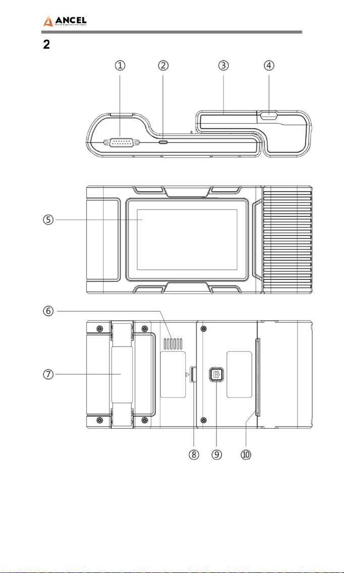
Product Structure

HD Series
5
Serial No. Name Function Description
①
Main Testing
Cable
Connection interface connects
vehicle communication cable during
vehicle diagnosis
②
USB Port
Used to connect to an external
computer
③
Print
Used to print diagnostic reports and
results
④
Paper bin
cover
After opening, you can install and
replace the printing paper
⑤
Touch
screen
Display content and touch operation
area
⑥
Speaker Device sound output
⑦
Auxiliary
bandage
Auxiliary for hand holding
⑧
Separation
switch
Host and printer separation switch
⑨
Test key
Printer self-test and paper feed
button
⑩
Paper outlet Printer paper outlet
Host Configuration
CPU
Quad-Core ARM Cortex-A7
RAM
1GB
Flash
8GB
Display
5 inches LCD, resolution ratio 800*480

HD Series
6
TP touch screen
Capacitive screen
WIFI
802.11b/g/n 2.4GHz
Horn
Support
USB interface
Type C interface
Diagnose
interface
DB15 interface
Operating
voltage
DC 10V~24V/3A
Operating
temperature
-20℃~60℃
Storage
temperature
-30℃~ 70℃
Printer Configuration (Optional)
Printer
80mm thermal printer
Print speed
60mm/s
Effective print width
72mm
Print resolution
203dpi 1mm=8dots
Print paper
specifications
80mm*30mm
Power On/Off
1) Power on
The device can be powered on in the following ways:
Vehicle power on: plug one end of the main diagnostic test line
into the DB-15 interface of the device, and the other end into the
diagnostic interface of the vehicle, and the device will

HD Series
7
automatically start up. If it doesn’t start up, it may be that there is
no power supply for the vehicle diagnostic seat, and the device
can be powered by the cigarette lighter or battery clamp.
Power on the power adapter: plug one end of the main
diagnostic test line into the DB-15 interface of the device,
connect the power adapter, and the device will start
automatically.
Note: the voltage of the power supply should be within the
scope of application of the product equipment. If it is
beyond the scope, the product may be damaged.
2) Power off
Before power off, please stop all diagnostic items and return
back to the main interface.
Pull out the diagnostic main test line from the diagnostic
interface of the vehicle. If the device is not equipped with
battery, the device will shut down automatically after
disconnecting the main test line from the diagnostic interface of
the vehicle.
Vehicle Diagnostic Preparation
The diagnostic program establishes data connection through
the vehicle electronic control system connected with the
equipment, which can read the vehicle diagnostic information,
view the data flow, and perform action test and other functions.
For details of the functions, please refer to the model which you
purchased.
To establish good communication between the diagnostic
program and the vehicle, the following operations need to be

HD Series
8
performed:
1) Turn off the ignition;
2) Find the diagnostic interface of the vehicle: it is usually
located on the driver side; If the diagnostic interface is not
found, please refer to the vehicle maintenance manual.
3) Insert one end of the diagnostic main test line into the
device DB-15 connector and tighten the retaining screws. The
other end is connected to the vehicle's diagnostic interface.
Note: Before the equipment is connected to the vehicle, it
is necessary to judge whether the diagnostic seat of the
vehicle is a standard OBD-II interface or a non-standard
OBD-II interface.
The vehicle compatible with OBD-II management system
only needs to use the integrated main test line OBD
connector to connect with the vehicle diagnosis seat and
provide power;
For vehicles that are not compatible with the OBD-II
management system, the corresponding connector should
be selected; Some vehicles need to be powered by other
vehicle power sources.
The following is an operation description of these two
connection modes.
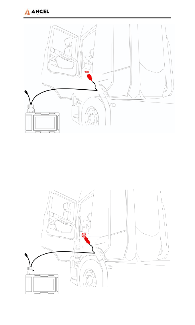
1) Connection of standard OBD-II interface
The vehicle connected with standard OBD-II interface only
needs to use the integrated main test line OBD connector, and
no other connectors are needed, as shown in the figure:
HD Series
9
2) Connection of non OBD-II interface
Vehicles with non OBD-II interface need to connect the main
test line with the corresponding special connector, as shown in
the figure:

HD Series
10
Note: at this time, the equipment is powered by the vehicle
diagnosis seat, and the equipment starts automatically. If not, it
may be that the vehicle diagnosis seat has no power supply,
and the equipment can be powered by the cigarette lighter or
battery clip.
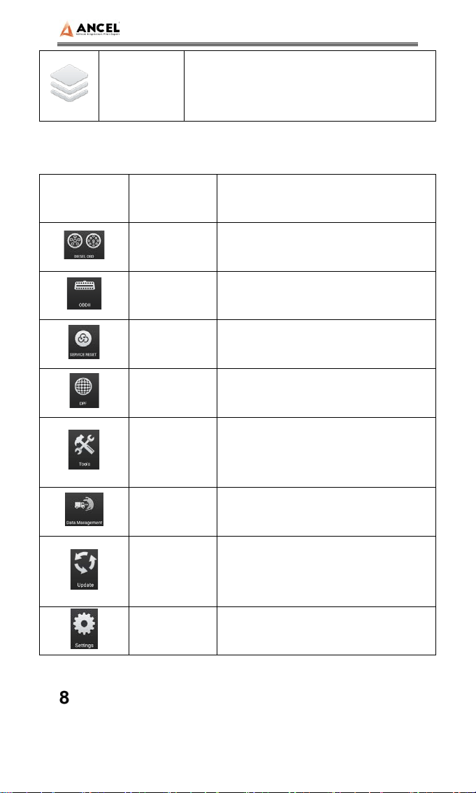
Introduction of Each Function Menu
After the system is started, the main menu of function will be
entered. The main menu of each version of model will be
slightly different. Please refer to the display of the model you
purchased.
1) Toolbar (see Table 1)
2) Function main menu (see Table 2)
Table 1: Toolbar
Icon
Function
name
Function description
Refresh Refresh upgrade menu
Home Return to the main interface of the system
Screenshot Capture current screen picture
Test report
Used to save test data during diagnosis
(can be viewed in data management
menu)
HD Series
11
Icon
Function
name
Function description
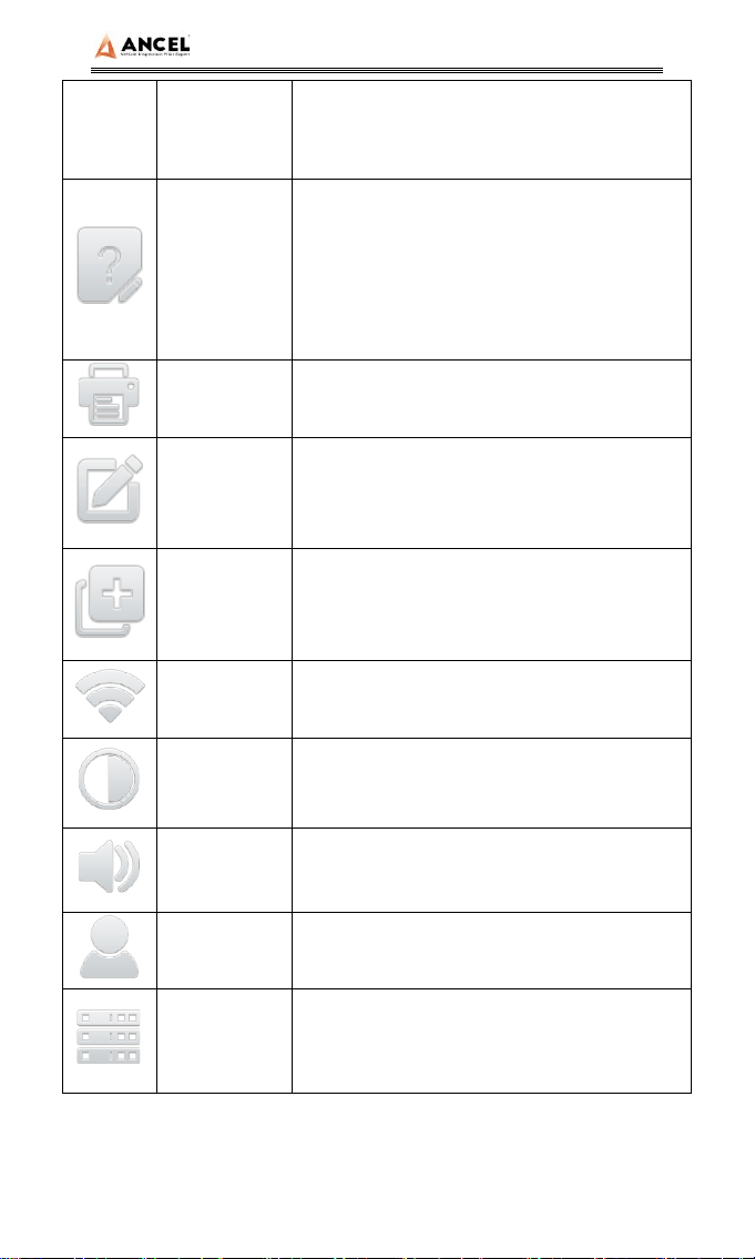
Feedback
Used to report the problem to the
company's service system (need to
connect to the network) when the system
cannot be accessed during the diagnosis
process
Print
Used to print test results or test reports.
The printer is optional
Edit
Used to edit files, lock, unlock or delete
files
Added Used to add feedback information
WIFI WIFI connection network
Brightness
Used to adjust the brightness of the
device screen
Volume Used to adjust the volume of the device
User info
Used to view device status and user
information
Data
cleaning
Used to remove useless data from the
device
HD Series
12
General
Used to set device language, unit and
time, view device information and restore
factory settings
Table 2: Function main menu
Icon
Function
name
Function description
Diesel OBD
Diagnostic procedure: Diesel OBD,
see section 5 for details
OBD-II
Diagnostic procedure: OBD-II, see
section 5 for details
Service
Reset
Reset the service lamps on the
instrument cluster.
DPF DPF regeneration
Tools
(Pin Detect)For the measurement of
pin voltage of diagnostic interface,
see section 6 for details
Data
management
For browsing and managing saved
data files, see section 7 for details
Update
For online upgrade of system
software and vehicle software, see
section 8 for details
Settings
Set and view system information,
see section 9 for details
Diagnostic Function
1) Take【Diesel OBD】as an example;
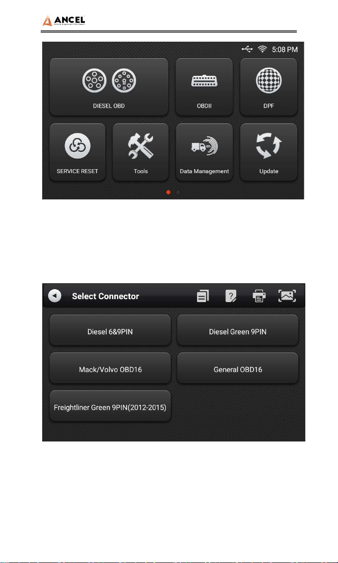
HD Series
13
Click【DIESEL OBD】menu enter the diagnosis interface.
2) Select connector according to the specific situation, such as
【Diesel6&9PIN】;
3) Select the required diagnostic method, such as 【Standard
protocol(Fast Scan)】;
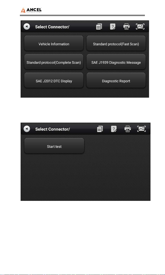
HD Series
14
4) Click 【Start test】
5) Select【(J1939) Engine】;
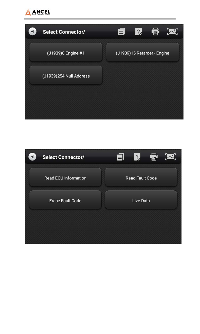
HD Series
15
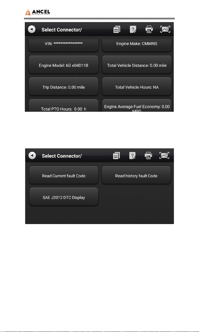
6) Enter【Diagnosis home page】;
The main diagnostic interface usually includes the
following options:
ECU Information: Read and display the control system module
information detected from ECU.
HD Series
16
Read Fault Code: Read the fault code information retrieved
from the vehicle system module.
Erase Fault Code: Clear the fault code and freeze frame data
retrieved from the vehicle system module
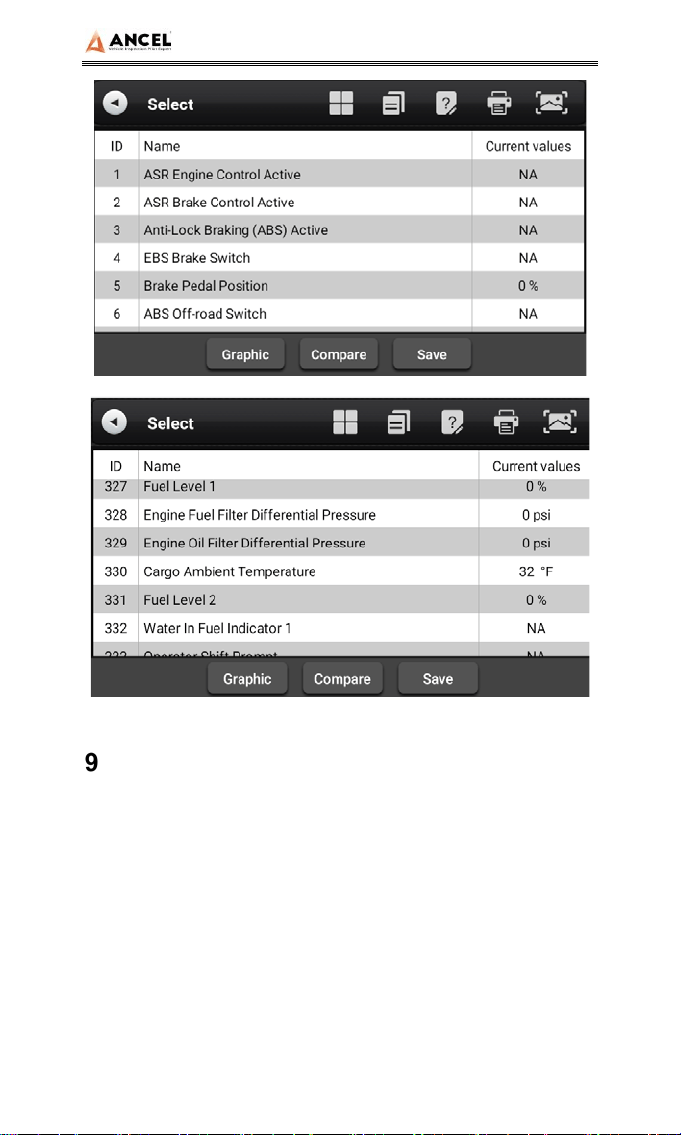
Live Data: Read and display the real-time operation
parameters of the current system module
HD Series
17
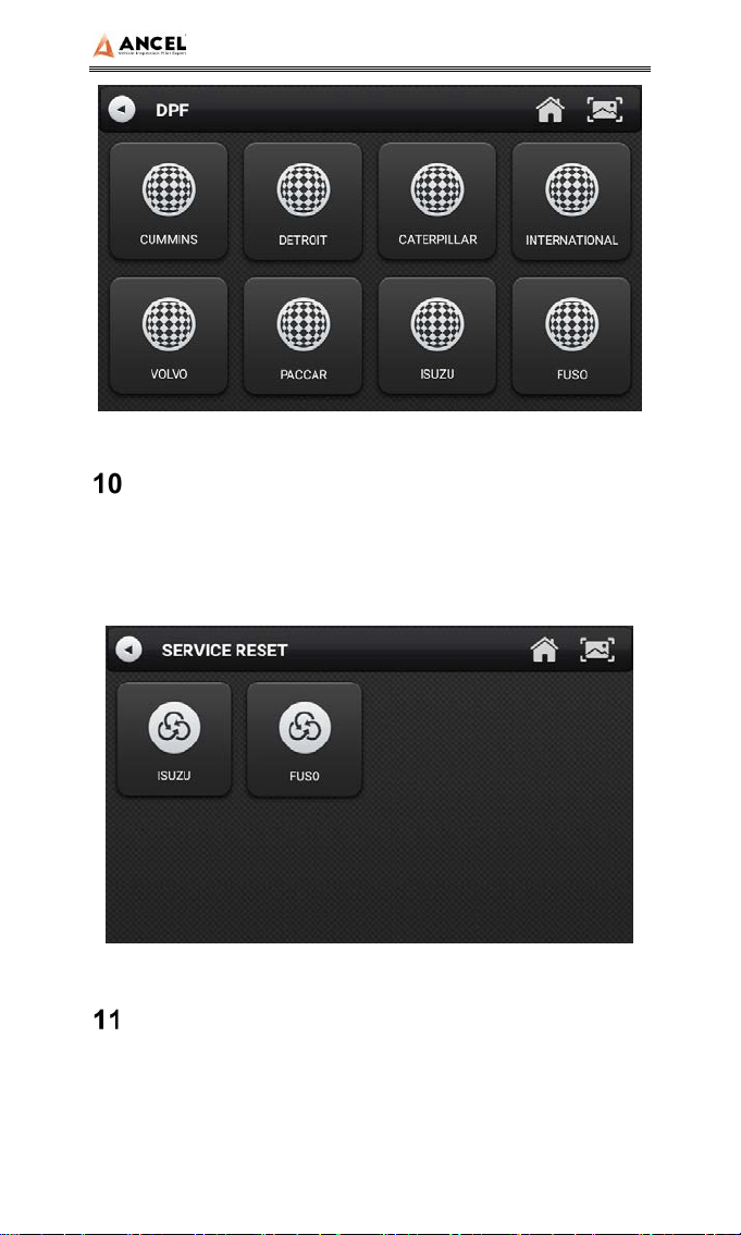
DPF Regeneration
Select【DPF】 in main menu, the screen will display the
vehicle model list and then operate according to the screen
prompt.
HD Series
18
Service Reset
Select 【Service Reset】to reset the service lamps on the
instrument cluster. The service system is designed to alert the
driver when the vehicle is due for a service.
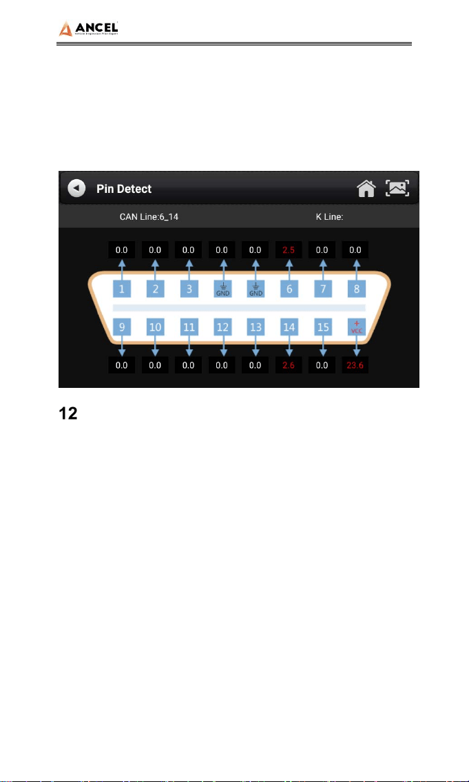
Pin Detect
This function mainly measures the voltage of 16 PIN of OBD
diagnostic interface, and judges the pin position of K- line and
CAN line.
HD Series
19
After connecting the OBD interface of vehicle, click the main
interface 【Tools】 to select pin detection. The program
automatically measures the 16pin voltage of OBD diagnosis
interface, and judges the pin position of K-line and can line, as
shown in the figure below:
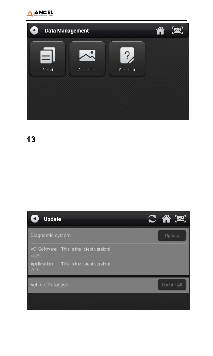
Data Management
【Data Management】The function is used to save and view
test reports, screenshots and problem feedback files. Most of
the files are generated by executing the toolbar operation of the
vehicle diagnosis interface.
HD Series
20
Diagnostic Software Upgrade
By connecting the device to the wireless network, the diagnostic
software can be upgraded and the product function can be
improved in time. Open 【Update】 in the function main menu,
and the system will automatically search for the latest update
program, as shown in the figure below. Click 【Update】 to
upgrade the model and other applications to the latest version.
HD Series
21
Settings
Select 【Settings】 from the main menu to open the setting
interface, where you can adjust the following system settings.
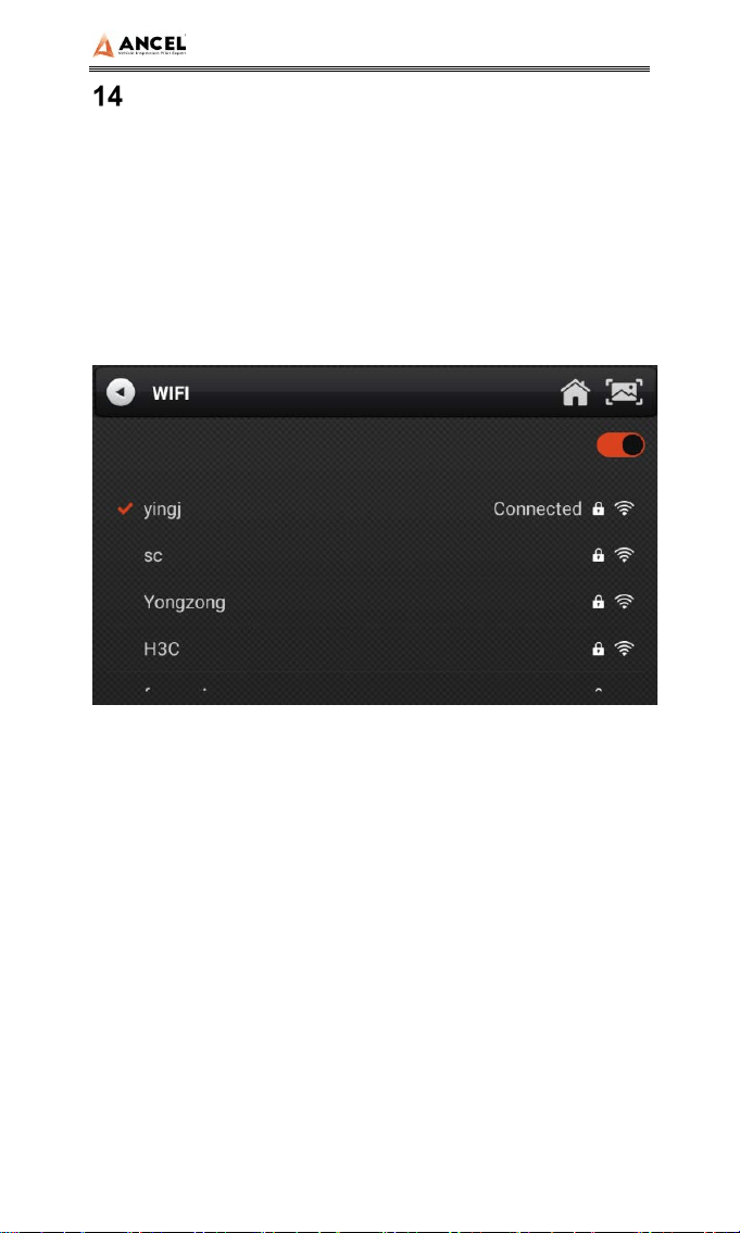
14.1 Wi-Fi Connection
The device supports wireless network connection for diagnosis
software upgrade and problem feedback.
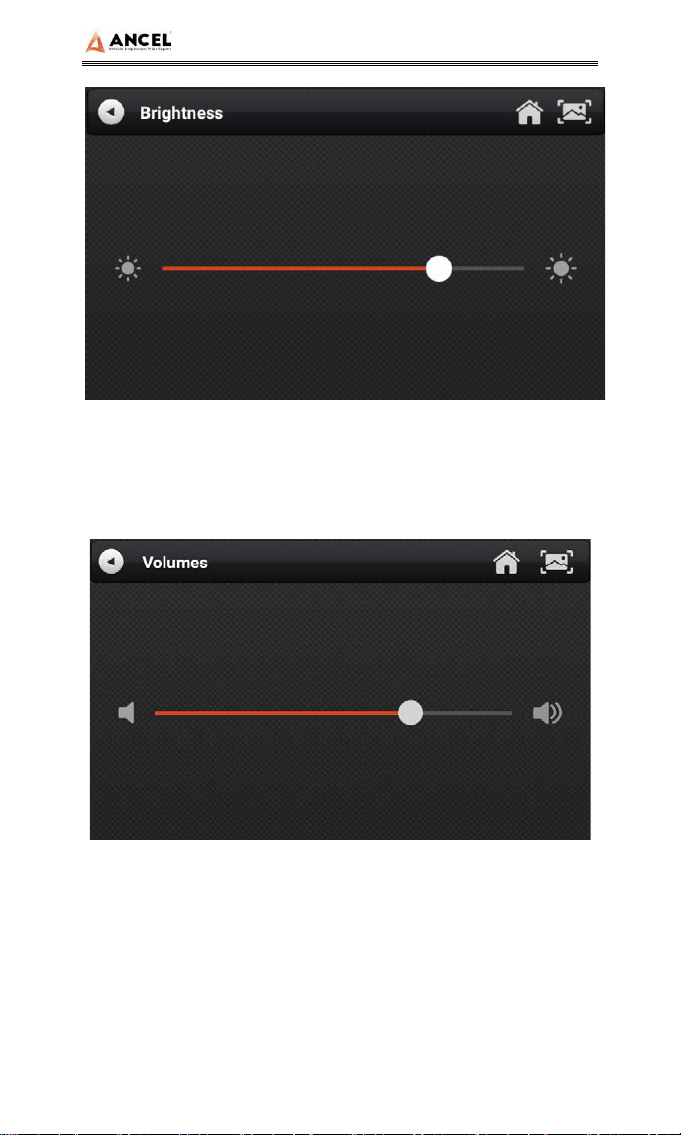
14.2 Brightness
The device supports screen brightness setting, please adjust it
according to your adaptive brightness.
HD Series
22
14.3 Volumes
The device supports volume adjustment.
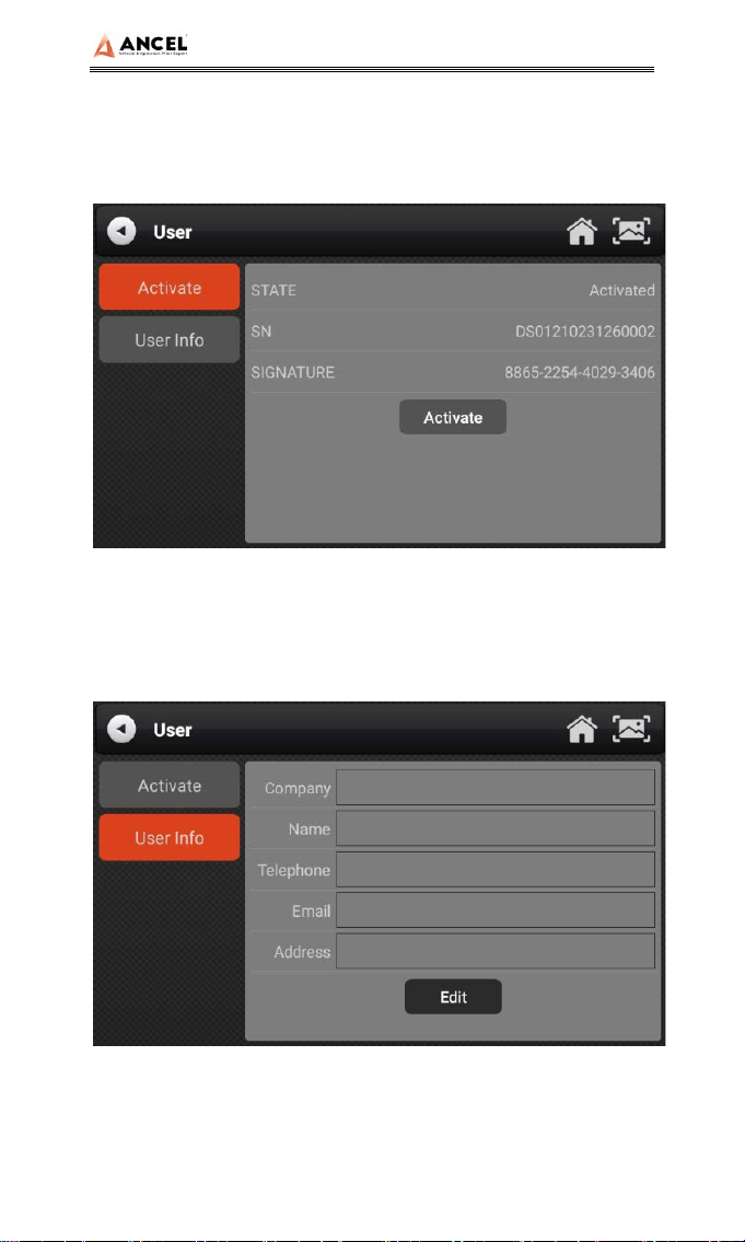
14.4 User Information and Activation
1) Activation
The products are not activated when they leave the factory.
Connect the network to enter the setting, and click
【Activation】 to activate the machine.
HD Series
23
Note: Please ensure that the device is connected to an
effective Wi-Fi network before performing the activation
operation.
2) User Info
Set your personal information: name, telephone, email,
address, etc.
HD Series
24
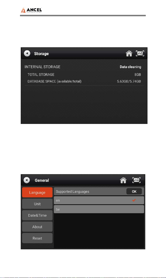
14.5 Storage
Cleaning up useless data with one click, freeing up more space
and cleaning up regularly will help the system run more stably.
14.6 General
1) Language
Please select settings based on the language you support for
the model you purchased.
HD Series
25
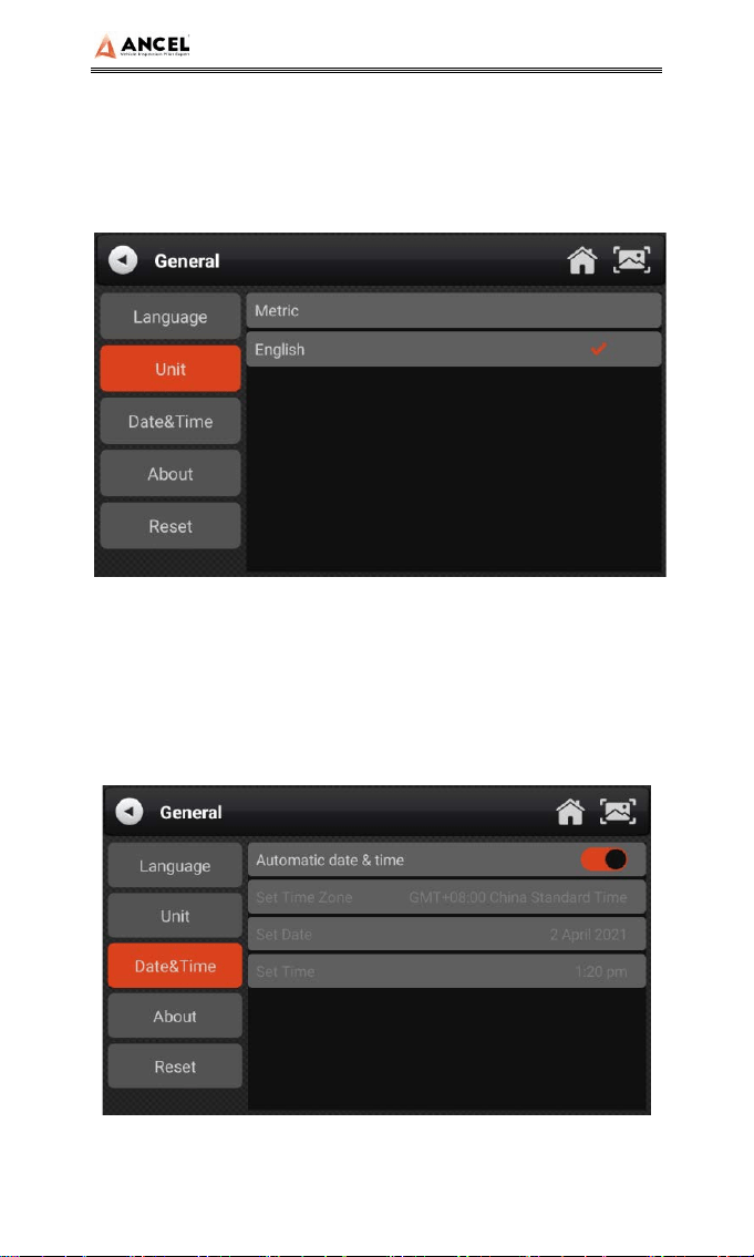
2) Unit
This option can set the data flow unit in the diagnostic
equipment software. Please select metric system or English
system as required.
3) Date&Time
This option can set the date / time of the device. The default is
automatic network synchronization update, or it can be set
manually.
HD Series
26
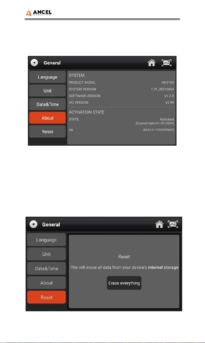
4) About
This option is used to look up the device model, version, serial
number, etc.
5) Reset
This option can restore the original settings of the device, which
will delete all the data stored in the device, including the
activation information and model data. You need to re-connect
the network to activate and download the model data package.
HD Series
27
Printer Introduction
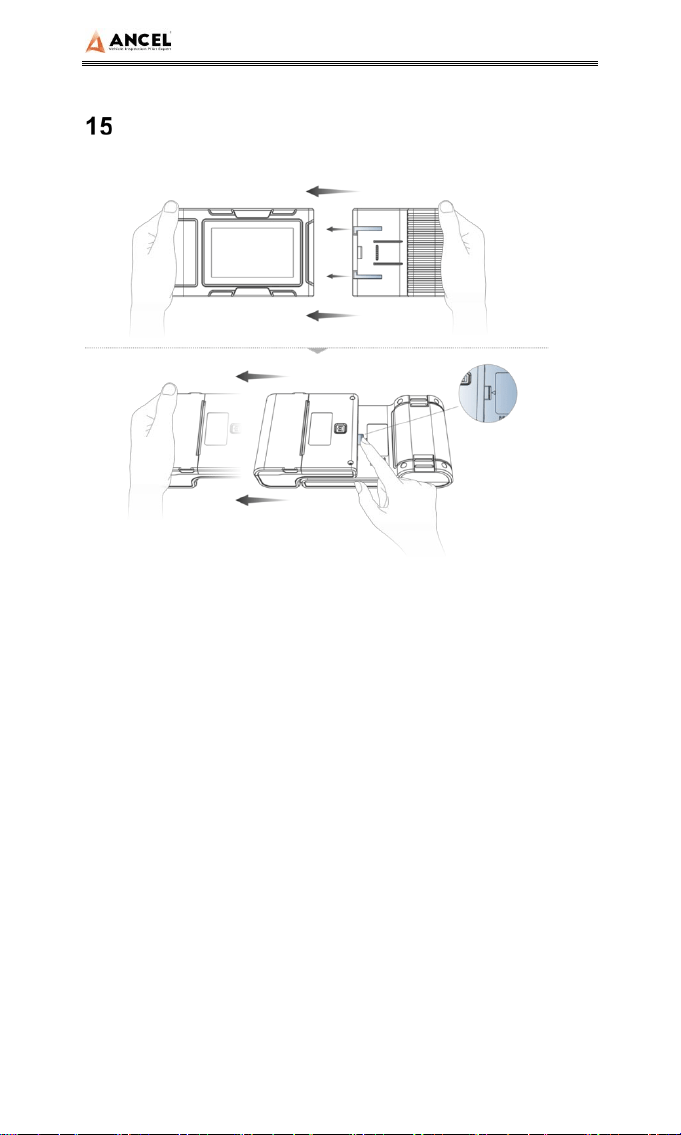
1) Printer combination and split
1. Hold the printer in your hand, aim at the lead-in slot on the
back of the main unit, push it in slightly, and you will hear a
“click” voice, which means the main unit and the printer
has already connected together.
2. After pressing the separation switch, hold the printer in
your hand and gently pull it out. The printer will be
separated from the host.
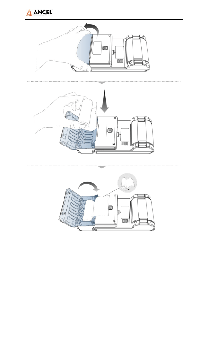
2) Printer loading and changing paper
HD Series
28
1. Hold the position of the printer paper bin cover with your
fingers and open the cover up;
2. Put the printing paper into the paper bin according to the
diagram. Pay attention to the direction of the paper. If the
installation is reversed, the printing will be blank;
3. Just close the paper bin cover.
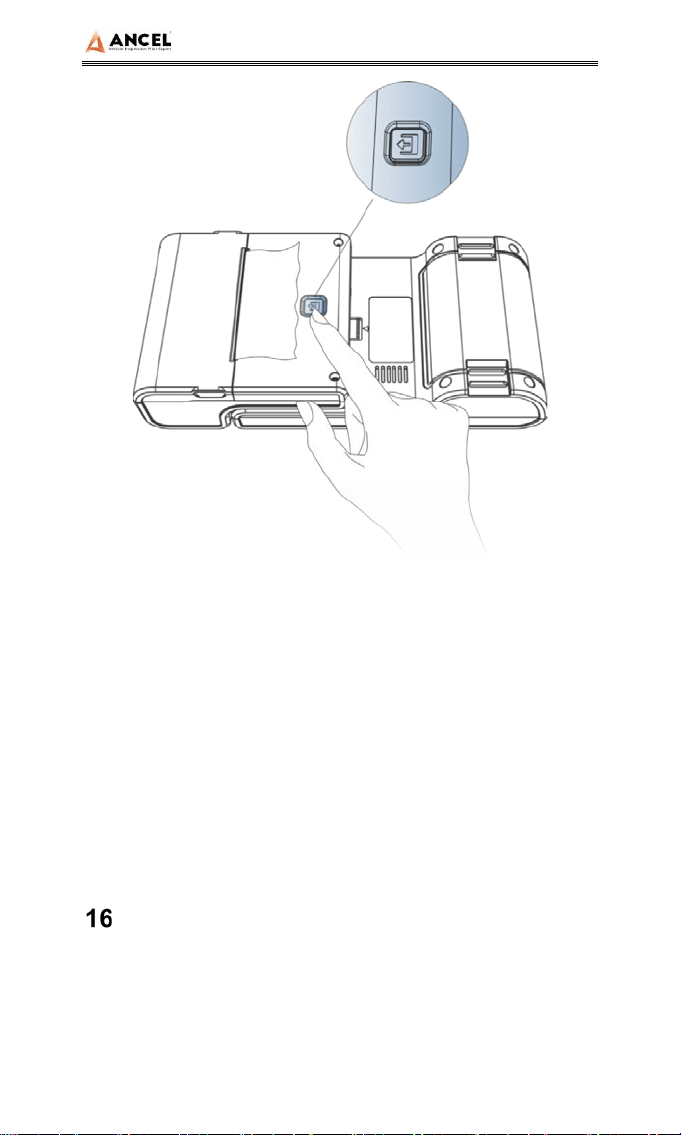
3) Printer self-test function
HD Series
29
1. When the machine is turned on, press the printer test key
briefly, and the printer will automatically print out a piece of
blank paper.
2. In the case of power on, long press the printer test key for
three seconds, the printer will automatically print a section
of self-test content, indicating that the printer function is
normal.
FAQ (Frequently Asked Questions)
Here are some frequently asked questions and
answers about the HD3300.
Question: I cannot activate and register the tool.

HD Series
30
Answer: There is no need to register the machine. If
your activation was failed, please kindly check your
network.
Question: What does the Simulate and DEMO
menus mean?
Answer: Simulate and DEMO are both DEMO menus,
not diagnosis function menus. The information in these
menus was collected according to the actual vehicle
diagnosis in the past, just for better understanding of
product functions for users.
Question: Will it work on new (2018) freight liner
with the new green connector?
Answer: Yes. The HD3300 machine has already
included new green 9pin connector.
Question: I can’t diagnose my vehicle with the
tool. It shows “ECU no response”.
Answer: Please do a voltage test via [pin detect]. If the
voltage is abnormal, please check the hardware first.

HD Series
31
Statement
This equipment has been tested and found to comply with the
limits for a Class B digital device, pursuant to Part 15 of the
FCC Rules. These limits are designed to provide reasonable
protection against harmful interference in a residential
installation. This equipment generates uses and can radiate
radio frequency energy and, if not installed and used in
accordance with the instructions, may cause harmful
interference to radio communications. However, there is no
guarantee that interference will not occur in a particular
installation. If this equipment does cause harmful interference to
radio or television reception, which can be determined by
turning the equipment off and on, the user is encouraged to try
to correct the interference by one or more of the following
measures:
-- Reorient or relocate the receiving antenna.
-- Increase the separation between the equipment and receiver.
-- Connect the equipment into an outlet on a circuit different
from that to which the receiver is connected.
-- Consult the dealer or an experienced radio/TV technician for
help.
Changes or modifications not expressly approved by the party
responsible for compliance could void the user's authority to
operate the equipment.
This device complies with part 15 of the FCC Rules. Operation
is subject to the following two conditions: (1) This device may
not cause harmful interference, and (2) this device must accept
any interference received, including interference that may
cause undesired operation.

HD Series
32
