
V1
BATTERY SYSTEM TESTER
OPERATING MANUAL
BST600
148.5 mm 148.5 mm
210 mm

resistance. But it can be predicted the life of the battery will be over soon
from the sudden increase of it's internal resistance and decrease of it's
conductance.
6-4 Is the CCA value tested by this tester correct?
CCA is considered as a control standard with the produce of the battery.
According to the accumulated records, the tested value of new battery is
10-15% higher than the standard value, and along with consuming of the
battery, the value is getting close to standard, even lower afterward.
6-5 What is the difference between the method of this tester and the
load test method?
The load test method: According to the physical formula R=V/1, test
equipment forcibly make the high permanent DC current ( presently 40-80A
large current is available ) go through the battery shortly ( about 2-3
seconds). And then the tested voltage of the battery can be used to figure out
the internal resistance by the formula.
Disadvantages of load test method:
(1) Just available for large capacitance battery or storage battery. The small
capacitance battery can not load 40-80A large current in 2-3 seconds.
(2) When the large current going through the battery, there comes out
polarization phenomenon from internal electrode, which can cause
polarization internal resistance. As a result it has to be tested in a short time.
Otherwise there is a large error of the internal resistance value.
(3) The internal electrode will be damage generally when large current go
through the battery.
The method of this tester: Battery is actually equivalent to an active
resistance. So we add a fixed frequency and small current to it, and then
sample the voltage value. Eventually the internal resistance can be figured
out after some operation such as rectification and smoothing.
Advantages of this method:
(1) It can be used for checking almost all the batteries including low capacity
battery and internal resistance of the notebook battery exclusively.
(2) It will not harm the battery to use this method.
………… ………………………………………………… …1
…………………… …………… …………… …1
…………………… …………… …………… …2
……………………………………………… …………… …2
…… ……………………………… …………… …………3
……… …………… …………… …………… …4
………………………………………… …… ……… ……6
……… ……… …… …………… …………… …… ……7
……………… …… ……… …… …………… …9
……………… …………… …… ……… …… …………… …9
……………… …………… …… ……… …… …………… …………… ……10
1 Brief Introduction.
2 Safety Rules And Precautions.
3 International Electric Symbol.
4 Structure Of Meter.
5.Operation Instruction
5 1 BATTERY CAPACITY TEST- .
5 2 CRANKING TEST- .
5 3 CHARGE SYSTEM- .
5 4 TEST REPORT PRINTING- .
5 5 DATA REVIEW- .
6 FAQ.
Content
11

5-5-2
Review every last test result of BATTERY CAPACITY , CRANKING
TEST,CHARGE SYSTEM by pressing < O > .
6.FAQ
6-1 What is the measurement principle of this tester?
The battery will gradually aging with increase of time. The main reason is
that it can no longer generate some effectively chemical reaction because of
aging of the surface of the battery plate. That is why most of the batteries can
longer be used mainly. International Electric and Electronic Engineer
Association(IEEE)formally looks the Conductivity Test as one of the standard
of checking lead acid storage battery. It points out from IEEE standard
1118-1996 that : Conductivity Test is used to test AC current generated by
putting the known frequency and amplitude AC signal to both sides of the
battery. AC conductivity value is the ratio of AC current signal which keeps
same phase with AC voltage and the AC voltage. This tester is designed from
this principle actually.
6-2 Is the result affected by the installation of negative current for the
vehicle?
All the negative currency will affect the result. Therefore please remove
the negative currency prior to checking, in order to achieve the accurate data.
6-3 Can this tester predict when the battery goes down?
The internal resistance of the sealed lead-acid battery is complicated. It
is generated by ohm internal resistance, concentration polarization internal
resistance, chemical reactions internal resistance and interference effect
caused by double capacitance’s charging. The ingredient of internal
resistance and its relative content will change with different test method and
different test moment, which can lead to different tested value of the internal
resistance. And there is no strict relationship between internal resistance (or
conductance ) and capacitance of the sealed lead - acid battery. So it is
impossible to predict the life of battery according to a single battery’s internal
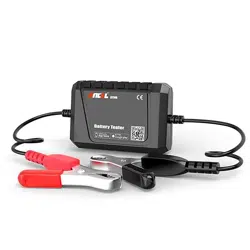
1 Brief Introduction
BST600 is used for lead-acid starting battery, testing the following
conditions of the battery, cranking system and charging system.
This tester supplies readings by a large color screen display with great
design of easy-to-use buttons operation,intelligent test methods and reverse
polarity protection.It makes operation safe,clear and convenient.
So this is the best tool in the fields of battery sales, vehicle repair and
battery inspection in equipment system associated with lead-acid starting
battery.
2. Safety Rules and Precautions
This manual includes instruction, operation warning and maintenance.
Damage to the meter may occur if it is not operated following the rules
in this manual. This tester is designed and produced strictly according to
IEC/EN61010-1 safety standard. Also it reaches double insulation over
voltage standard CATⅢ 600V and pollution degree 2 .
(1) Available for 12V and 24V Lead - Acid Starting Battery.The working
voltage is DC 9V to 35V.
(2) The voltage value will be higher than that in the normal situation after
the checked battery being fully charged . Please turn on the headlights
for 2 to 3 minutes, then check the battery when it's voltage drops to the
normal value.
(3) Check the insulating layer of the clamps before testing. It should be
operated without any damage, bareness or disconnection. Also it is
not allowed to use it when the housing is not covered completely or
correctly, which will cause electric shock.
(4) Do not use or store the tester in the condition of high temperature, high
humidity, combustibility, explosion and strong electromagnetic field.
(5) Do not modify the internal circuit in order to avoid damage to the tester
and injury to user.
(6) Wear proper eye mask when testing or repairing in order to avoid some
objects hitting eyes from the engine.
(7) Keep the site ventilated when testing or repairing in order to avoid
inhaling some toxic gas.
(8) When the engine is running, do not place the tester or accessories beside
the engine or exhaust pipe in order to avoid damage by high temperature.
(9) Pay attention to the precautions and maintenance procedure of the
manufacturer during repairing.
.
1 10

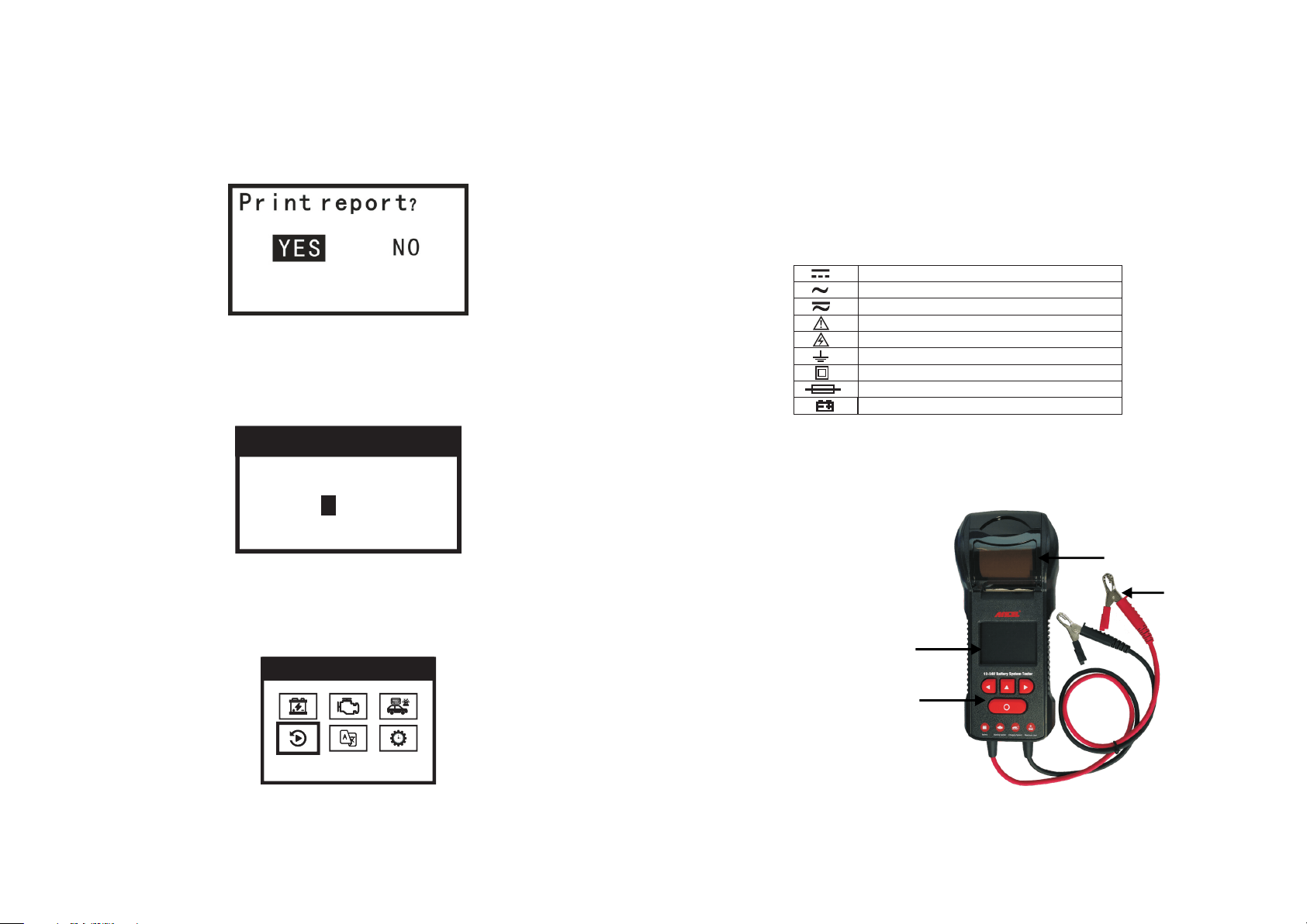
DC
AC
DC/AC
WARNING
HIGH VOLTAGE ( ELECTRIC SHOCK )
EARTH
DOUBLE INSULATION
FUSE
BATTERY
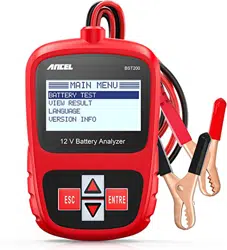
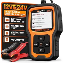
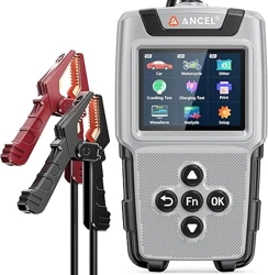
4 Structure of Meter
< >:
< ▶ >:decrease the value / page down
< ▲ >:cancel / return
< O > confirm / test
Red Clamp : positive connection
Black Clamp : negative connection
.
◀ increase the value / page up
:
(10)Standard of optional storage battery:
CCA:100~2000 IEC:100~1400
BCI:100~2000 EN:100~2000
CA :100~2000 DIN:100~1400
MCA:100~2000 SAE:100~2000
JIS:26A17 – 245H52 GB:100~1400
(100~2000 CCA)
3 International Electric Symbol .
5 4 TEST REPORT PRINTING
5-4-1.
Test report printing is available for every finished test.Press < O > to
Test Report Printing Interface as below to confirm printing or not.
5-4-2.
VIN code of tested vehicle is required before printing report.
5-4-3.
Press < ◀ > < ▶ > to set VIN code. < O > is used for confirming every
digit until last one.
5-5. DATA REVIEW
5-5-1
Press < ◀ > < ▶ > to select “ DATA REVIEWING” at MAIN MENU interface.
- .
9 2
23
23
MA I N ME N U
DA T A R E V I EW
Color Screen Display
Button
Test Clamps
Thermal Printer
00 00
Las t 4 o f V IN
5 3 3.
Press < O > to Charging Test interface.Start engine as guide displayed
in the screen.
5-3-4.
Test result will be displayed as below and auto saved for reviewing.
5-3-5
Press < O > to print the report.Please refer to 5-4 TEST REPORT PRINTING.
Press < ▲ > to return to main menu.
Charge System Result Reference Table
- -
5 Operation Instruction
The tester is powered by the vehicle battery. Please connect the RED
clamp to the positive terminal, and connect the Black clamp to the negative
terminal. Connect the RED clamp prior to Black one is suggested.
The tester is ready to use along with the screen displays as below.
Please check and reconnect two clamps fully and firmly connected to
the terminals in case the screen displays as below.
Select language and set date and time as below.
.
3 8
12
24
24
12 . 5 7 V
20 2 1 - 0 4 - 2 1 1 6 :0 3: 59
En g li sh
LA N GU A G E SE T TI N G
23
23
MA I N ME N U
LA N G U A G E SE T
CH A RG E S Y ST E M
Tu r n o n a l l l o a d s
sp e e d u p t o 2 0 0 0
to 2 5 0 0 r p m , t h e n
pr e s s < E n t e r > .
R I P P L E : 9 1 m V
L O A D E D : 1 3 . 9 2 V
U N L O A D E D : 1 3 . 9 3 V
C H AR G I N G G O O D
CH A RG E S Y ST E M
Reference Table (For 12V System)
Status Battery Voltage Engine Performance
All Electric System
Off(Depress
Accelerator)
> 13.5 Normal
13.2~13.5 General
13.0~13.2 Keep Caution
< 13 Inspection Immediately
All Electric System
On
(Depress
Accelerator)
13.4~14. 6 Normal
13.2~13.4 Keep Caution
< 13.2 Inspection Immediately
For reference only. Bad batteries will affect the test results.
23
23
MA I N ME N U
TI M E A D J U ST
TI M E AD J U ST
DA T E
20 2 1 - 0 4 - 2 1
16 : 0 7 : 4 2
TI M E
Press to return to main menu.
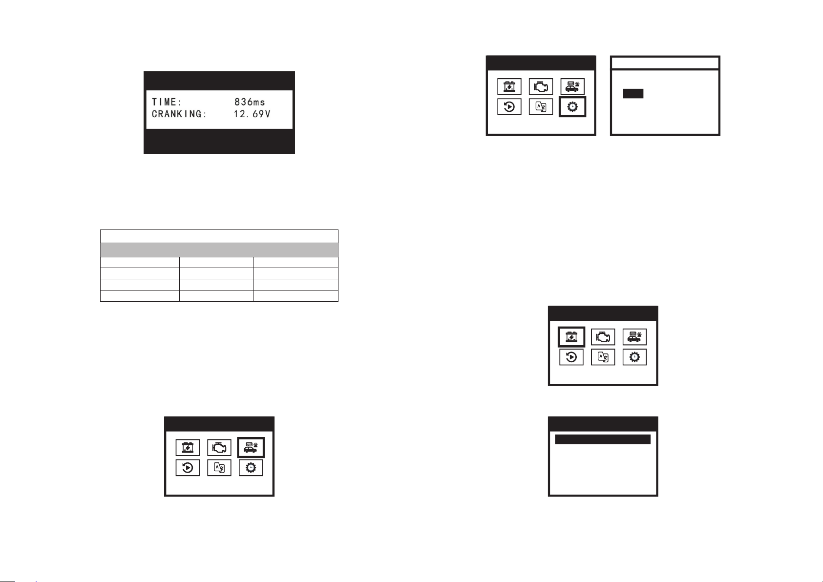
Reading over 9.6V ( for 24V system, reading over 16V ) means cranking
is good.
Reading below 9.6V ( for 24V system, reading below 16V ) means cranking
is abnormal. Please check associated parts , such as connections, wires,
starter and battery's terminal corrupted or not.
Cranking Test Result Reference Table
5-3. CHARGE SYSTEM
This test determines charging system by testing its condition under
loaded and unloaded status.
5-3-1.
First make sure the engine and all devices are off.
5-3-2.
Press < ◀ > < ▶ > to select “ CHARGE SYSTEM”.
< ▲ >
7 4
5 1 BATTERY CAPACITY TEST
This tester determines condition of battery according to rated value labeled
on the battery.
5-1-1.
First make sure the engine and all devices are off.The voltage value
will be higher than that in the normal situation due to the checked battery is
fully charged after the vehicle runs for a while. Please turn on the headlights
for 2 to 3 minutes, until its voltage drops to the normal value,then turn off
all devices and start testing.
5-1-2.
Press < ◀ > < ▶ > to select “BATTERY CAPACITY” and press < O > to
continue.
5-1-3.
Press < ◀ > < ▶ >to select “BATTERY TYPE” and press < O > to continue.
- .
23
23
MA I N ME N U
BA T T E R Y C AP A C I TY
1.
2.
3.
4.
5.
BA T TE R Y T YP E
Re g u l a r F l o o d e d
AG M F l a t P l a t e
AG M S p i r a l
GE L
EF B
23
23
MA I N ME N U
CH A R G E S Y ST E M
Reference Table (For 12V System)
Cranking Voltage Cranking Ability Action to Battery
> 10.7 V Good No Action
10.2 ~ 10.7 V
Normal Keep Caution
9.6 ~ 10.2 V
Bad Replace It Soon
< 9.6 V Very Bad Replace It Immediately
CR A NK IN G TE S T
CRA N K I N G GOOD
CC A
1/ 10
Se l ec t I n pu t
5-1-4.
Press < ◀ > < ▶ > to select CCA TYPE which is displayed on the
battery rating label,and press < > to continue.
5-1-5.
Press < ◀ > < ▶ > to select CCA RATED which is displayed on the
battery rating label.
5-1-6.
Press < O > to start Battery Test. The test result will be displayed as
below and auto saved for reviewing.
5-1-7.
Press < O > to print the report.Please refer to 5-4 TEST REPORT PRINTING.
Press < ▲ > to return to main menu.
O
Battery State of Health (SOH) and Test Result Reference Table
two series connection 12V batteries when testing 24V system.
5-2 CRANKING TEST
This test determines cranking state by testing cranking voltage and time.
5-2-1.
First make sure the engine and all devices are off.
5-2-2.
Press < ◀ > < ▶ > to select “ CRANKING TEST” .
5-2-3.
Press < O > to Cranking Test interface.Start engine as guide displayed
in the screen.
5-2-4.
Test result will be displayed as below and auto saved for reviewing.
5-2-5
Press < O > to print the report. Please refer to 5-4 TEST REPORT
PRINTING.
Please note that Internal Resistance refers to the sum total resistance of
.
5 6
23
23
MA I N ME N U
CR A N K I N G TE S T
LIFE RESULT NOTE
>80% GREAT Good to Use
>60% NORMAL Not Bad
>45% CAUTION Keep Caution
<45% SUGGEST REPLACE! Replace Needed
CC A R AT ED
BA T TE RY C AP A CI TY
23
23
MA I N ME N U
TI M E A D J U ST
TI M E AD J U ST
DA T E
20 2 1 - 0 4 - 2 1
16 : 0 7 : 4 2
TI M E
Press to return to main menu.
Reading over 9.6V ( for 24V system, reading over 16V ) means cranking
is good.
Reading below 9.6V ( for 24V system, reading below 16V ) means cranking
is abnormal. Please check associated parts , such as connections, wires,
starter and battery's terminal corrupted or not.
Cranking Test Result Reference Table
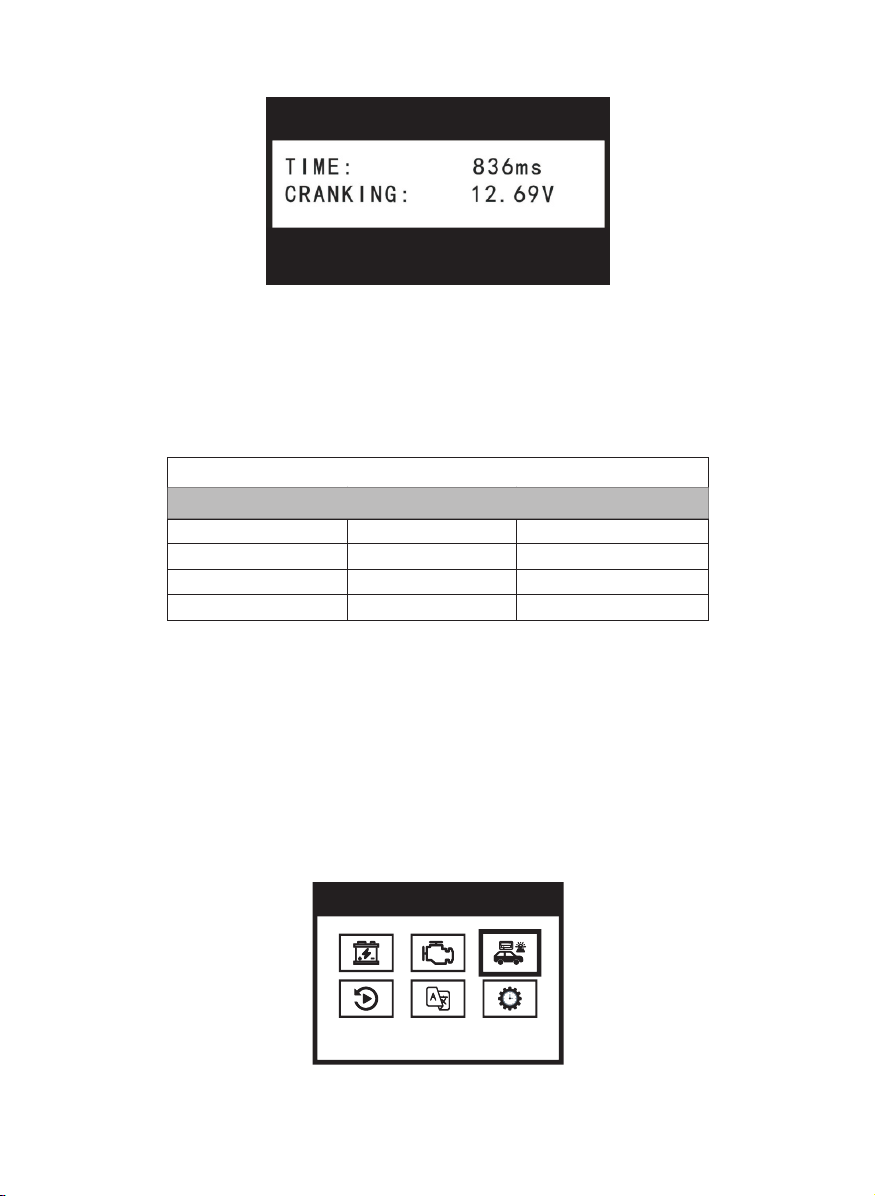
5-3. CHARGE SYSTEM
This test determines charging system by testing its condition under
loaded and unloaded status.
5-3-1.
First make sure the engine and all devices are off.
5-3-2.
Press < ◀ > < ▶ > to select “ CHARGE SYSTEM”.
< ▲ >
7 4
5 1 BATTERY CAPACITY TEST
This tester determines condition of battery according to rated value labeled
on the battery.
5-1-1.
First make sure the engine and all devices are off.The voltage value
will be higher than that in the normal situation due to the checked battery is
fully charged after the vehicle runs for a while. Please turn on the headlights
for 2 to 3 minutes, until its voltage drops to the normal value,then turn off
all devices and start testing.
5-1-2.
Press < ◀ > < ▶ > to select “BATTERY CAPACITY” and press < O > to
continue.
5-1-3.
Press < ◀ > < ▶ >to select “BATTERY TYPE” and press < O > to continue.
- .
23
23
MA I N ME N U
BA T T E R Y C AP A C I TY
1.
2.
3.
4.
5.
BA T TE R Y T YP E
Re g u l a r F l o o d e d
AG M F l a t P l a t e
AG M S p i r a l
GE L
EF B
23
23
MA I N ME N U
CH A R G E S Y ST E M
Reference Table (For 12V System)
Cranking Voltage Cranking Ability Action to Battery
> 10.7 V Good No Action
10.2 ~ 10.7 V
Normal Keep Caution
9.6 ~ 10.2 V
Bad Replace It Soon
< 9.6 V Very Bad Replace It Immediately
CR A NK IN G TE S T
CRA N K I N G GOOD
5 3 3.
Press < O > to Charging Test interface.Start engine as guide displayed
in the screen.
5-3-4.
Test result will be displayed as below and auto saved for reviewing.
5-3-5
Press < O > to print the report.Please refer to 5-4 TEST REPORT PRINTING.
Press < ▲ > to return to main menu.
Charge System Result Reference Table
- -
5 Operation Instruction
The tester is powered by the vehicle battery. Please connect the RED
clamp to the positive terminal, and connect the Black clamp to the negative
terminal. Connect the RED clamp prior to Black one is suggested.
The tester is ready to use along with the screen displays as below.
Please check and reconnect two clamps fully and firmly connected to
the terminals in case the screen displays as below.
Select language and set date and time as below.
.
3 8
12
24
24
12 . 5 7 V
20 2 1 - 0 4 - 2 1 1 6 :0 3: 59
En g li sh
LA N GU A G E SE T TI N G
23
23
MA I N ME N U
LA N G U A G E SE T
CH A RG E S Y ST E M
Tu r n o n a l l l o a d s
sp e e d u p t o 2 0 0 0
to 2 5 0 0 r p m , t h e n
pr e s s < E n t e r > .
R I P P L E : 9 1 m V
L O A D E D : 1 3 . 9 2 V
U N L O A D E D : 1 3 . 9 3 V
C H AR G I N G G O O D
CH A RG E S Y ST E M
Reference Table (For 12V System)
Status Battery Voltage Engine Performance
All Electric System
Off(Depress
Accelerator)
> 13.5 Normal
13.2~13.5 General
13.0~13.2 Keep Caution
< 13 Inspection Immediately
All Electric System
On
(Depress
Accelerator)
13.4~14. 6 Normal
13.2~13.4 Keep Caution
< 13.2 Inspection Immediately
For reference only. Bad batteries will affect the test results.
DC
AC
DC/AC
WARNING
HIGH VOLTAGE ( ELECTRIC SHOCK )
EARTH
DOUBLE INSULATION
FUSE
BATTERY
4 Structure of Meter
< >:
< ▶ >:decrease the value / page down
< ▲ >:cancel / return
< O > confirm / test
Red Clamp : positive connection
Black Clamp : negative connection
.
◀ increase the value / page up
:
(10)Standard of optional storage battery:
CCA:100~2000 IEC:100~1400
BCI:100~2000 EN:100~2000
CA :100~2000 DIN:100~1400
MCA:100~2000 SAE:100~2000
JIS:26A17 – 245H52 GB:100~1400
(100~2000 CCA)
3 International Electric Symbol .
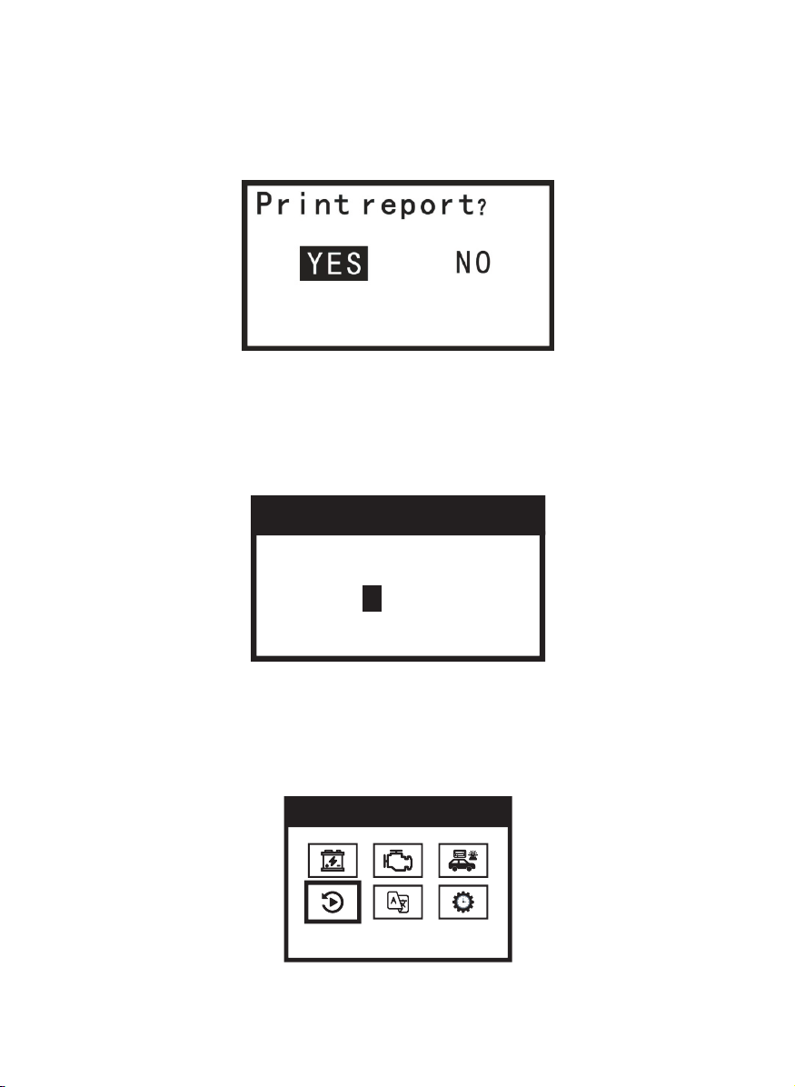
5 4 TEST REPORT PRINTING
5-4-1.
Test report printing is available for every finished test.Press < O > to
Test Report Printing Interface as below to confirm printing or not.
5-4-2.
VIN code of tested vehicle is required before printing report.
5-4-3.
Press < ◀ > < ▶ > to set VIN code. < O > is used for confirming every
digit until last one.
5-5. DATA REVIEW
5-5-1
Press < ◀ > < ▶ > to select “ DATA REVIEWING” at MAIN MENU interface.
- .
9 2
23
23
MA I N ME N U
DA T A R E V I EW
Color Screen Display
Button
Test Clamps
Thermal Printer
00 00
Las t 4 o f V IN

5-5-2
Review every last test result of BATTERY CAPACITY , CRANKING
TEST,CHARGE SYSTEM by pressing < O > .
6.FAQ
6-1 What is the measurement principle of this tester?
The battery will gradually aging with increase of time. The main reason is
that it can no longer generate some effectively chemical reaction because of
aging of the surface of the battery plate. That is why most of the batteries can
longer be used mainly. International Electric and Electronic Engineer
Association(IEEE)formally looks the Conductivity Test as one of the standard
of checking lead acid storage battery. It points out from IEEE standard
1118-1996 that : Conductivity Test is used to test AC current generated by
putting the known frequency and amplitude AC signal to both sides of the
battery. AC conductivity value is the ratio of AC current signal which keeps
same phase with AC voltage and the AC voltage. This tester is designed from
this principle actually.
6-2 Is the result affected by the installation of negative current for the
vehicle?
All the negative currency will affect the result. Therefore please remove
the negative currency prior to checking, in order to achieve the accurate data.
6-3 Can this tester predict when the battery goes down?
The internal resistance of the sealed lead-acid battery is complicated. It
is generated by ohm internal resistance, concentration polarization internal
resistance, chemical reactions internal resistance and interference effect
caused by double capacitance’s charging. The ingredient of internal
resistance and its relative content will change with different test method and
different test moment, which can lead to different tested value of the internal
resistance. And there is no strict relationship between internal resistance (or
conductance ) and capacitance of the sealed lead - acid battery. So it is
impossible to predict the life of battery according to a single battery’s internal
1 Brief Introduction
BST600 is used for lead-acid starting battery, testing the following
conditions of the battery, cranking system and charging system.
This tester supplies readings by a large color screen display with great
design of easy-to-use buttons operation,intelligent test methods and reverse
polarity protection.It makes operation safe,clear and convenient.
So this is the best tool in the fields of battery sales, vehicle repair and
battery inspection in equipment system associated with lead-acid starting
battery.
2. Safety Rules and Precautions
This manual includes instruction, operation warning and maintenance.
Damage to the meter may occur if it is not operated following the rules
in this manual. This tester is designed and produced strictly according to
IEC/EN61010-1 safety standard. Also it reaches double insulation over
voltage standard CATⅢ 600V and pollution degree 2 .
(1) Available for 12V and 24V Lead - Acid Starting Battery.The working
voltage is DC 9V to 35V.
(2) The voltage value will be higher than that in the normal situation after
the checked battery being fully charged . Please turn on the headlights
for 2 to 3 minutes, then check the battery when it's voltage drops to the
normal value.
(3) Check the insulating layer of the clamps before testing. It should be
operated without any damage, bareness or disconnection. Also it is
not allowed to use it when the housing is not covered completely or
correctly, which will cause electric shock.
(4) Do not use or store the tester in the condition of high temperature, high
humidity, combustibility, explosion and strong electromagnetic field.
(5) Do not modify the internal circuit in order to avoid damage to the tester
and injury to user.
(6) Wear proper eye mask when testing or repairing in order to avoid some
objects hitting eyes from the engine.
(7) Keep the site ventilated when testing or repairing in order to avoid
inhaling some toxic gas.
(8) When the engine is running, do not place the tester or accessories beside
the engine or exhaust pipe in order to avoid damage by high temperature.
(9) Pay attention to the precautions and maintenance procedure of the
manufacturer during repairing.
.
1 10

resistance. But it can be predicted the life of the battery will be over soon
from the sudden increase of it's internal resistance and decrease of it's
conductance.
6-4 Is the CCA value tested by this tester correct?
CCA is considered as a control standard with the produce of the battery.
According to the accumulated records, the tested value of new battery is
10-15% higher than the standard value, and along with consuming of the
battery, the value is getting close to standard, even lower afterward.
6-5 What is the difference between the method of this tester and the
load test method?
The load test method: According to the physical formula R=V/1, test
equipment forcibly make the high permanent DC current ( presently 40-80A
large current is available ) go through the battery shortly ( about 2-3
seconds). And then the tested voltage of the battery can be used to figure out
the internal resistance by the formula.
Disadvantages of load test method:
(1) Just available for large capacitance battery or storage battery. The small
capacitance battery can not load 40-80A large current in 2-3 seconds.
(2) When the large current going through the battery, there comes out
polarization phenomenon from internal electrode, which can cause
polarization internal resistance. As a result it has to be tested in a short time.
Otherwise there is a large error of the internal resistance value.
(3) The internal electrode will be damage generally when large current go
through the battery.
The method of this tester: Battery is actually equivalent to an active
resistance. So we add a fixed frequency and small current to it, and then
sample the voltage value. Eventually the internal resistance can be figured
out after some operation such as rectification and smoothing.
Advantages of this method:
(1) It can be used for checking almost all the batteries including low capacity
battery and internal resistance of the notebook battery exclusively.
(2) It will not harm the battery to use this method.
………… …… …………… …………… …………… …… …1
……………… …… ……… …… …………… …1
……………… …… ……… …… …………… …2
………… …… …………… …………… …… ……… …… …2
…… …………… …………… …… ……… …… …………3
……… ……… …… …………… …………… …4
……………… …………… …………… …… ……… ……6
……… ……… …… …………… …………… …… ……7
……………… …… ……… …… …………… …9
……………… …………… …… ……… …… …………… …9
……………… …………… …… ……… …… …………… …………… ……10
1 Brief Introduction.
2 Safety Rules And Precautions.
3 International Electric Symbol.
4 Structure Of Meter.
5.Operation Instruction
5 1 BATTERY CAPACITY TEST- .
5 2 CRANKING TEST- .
5 3 CHARGE SYSTEM- .
5 4 TEST REPORT PRINTING- .
5 5 DATA REVIEW- .
6 FAQ.
Content
11

V1
BATTERY SYSTEM TESTER
OPERATING MANUAL
BST600
148.5 mm 148.5 mm
210 mm