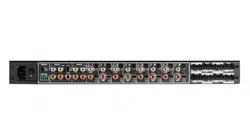
MULTI-CHANNEL POWER AMPLIFIER 8-50 | 16-50
QUICKSTART GUIDE
APPLICATION NOTES
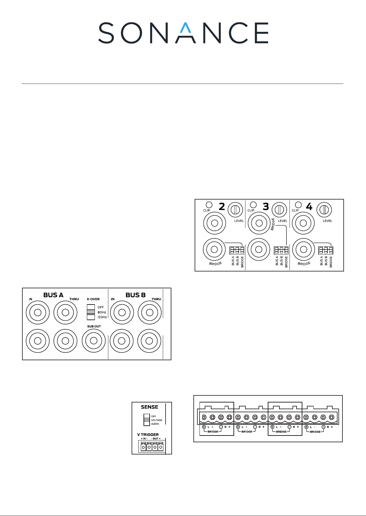
BUS CONNECTIONS
• BUS A LOW PASS X-OVER: Subwoofer crossover
can be set to 80Hz or 120 Hz. High Pass x-over will
impact the Left and Right BUS A channels as well
• Powering a Passive Subwoofer: Use RCA from
subwoofer output to an unused discrete line input
in BRIDGE mode
NOTE: Setting the X-OVER to 80Hz or 120Hz will
crossover the signal for any zone output using BUS A
(80Hz and above, or 120Hz and above)
Connect source audio cables to Bus A, Bus B, or
Direct, making sure to adjust DIP switch to appropriate
selection for each Zone Output.
SENSE SWITCH FOR POWER SELECTION
• Switch Set to “OFF”, Amp is
always powered on, ready to
play audio
• Switch Set to VOLTAGE”, Amp
will power on with 12V DC applied.
Use the output to pass through to
other amps
• Switch Set to “AUDIO”, Amplifier will power on
with audio signal after 4-6 seconds, and o with a
loss of audio signal after 15 minutes
ZONE INPUT CONNECTIONS
• Use RCA connections from discrete source to play
to associated zone (discrete inputs are always
active)
• Use DIP switch if using Bus A, Bus B, or to bridge
the speaker output
• Note the alternating Left or Right Discrete input
for bridged mode outputs
• Zone Level Control: Adjust in small increments to
correct output gain as needed
DIP switches to enable Bus A input, Bus B input, and
Bridge mode on each zone.
BUS INPUTS AND DIP SWITCHES
DIP Switch selections can include one or both BUS
inputs, and or BRIDGE. When more than one BUS
input is selected on the DIP switch, the audio signals
will be mixed and all will be played back in that zone.
This can be useful when one BUS includes paging or a
doorbell signal
SPEAKER CONNECTIONS
• Attach speaker wire (up to 12 gauge) with
included speaker block connectors for each zone
• Wiring for Bridge Mode: Use Left Positive and
Right Negative connections
Accepts speaker wire, up to 12 gauge. Note polarity
when connecting.
NOTE: Do not combine negative terminals. The amp is
not common ground type architecture.
BOX CONTENTS
(1) Quickstart Guide
(1) Sonance Amplifier (8-50 or 16-50 model)
(1) IEC Power Cord (Region Dependent)
(4) Amp Feet
(2) Rack Ears and Screws
(4) Block Connector for Speaker Outputs
(1) Block Connector for Voltage Trigger
3
1
ZONE 1 ZONE 2 ZONE 4ZONE 3
3
1
ZONE 1 ZONE 2 ZONE 4ZONE 3
3
1
ZONE 1 ZONE 2 ZONE 4ZONE 3
3
1
ZONE 1 ZONE 2 ZONE 4ZONE 3
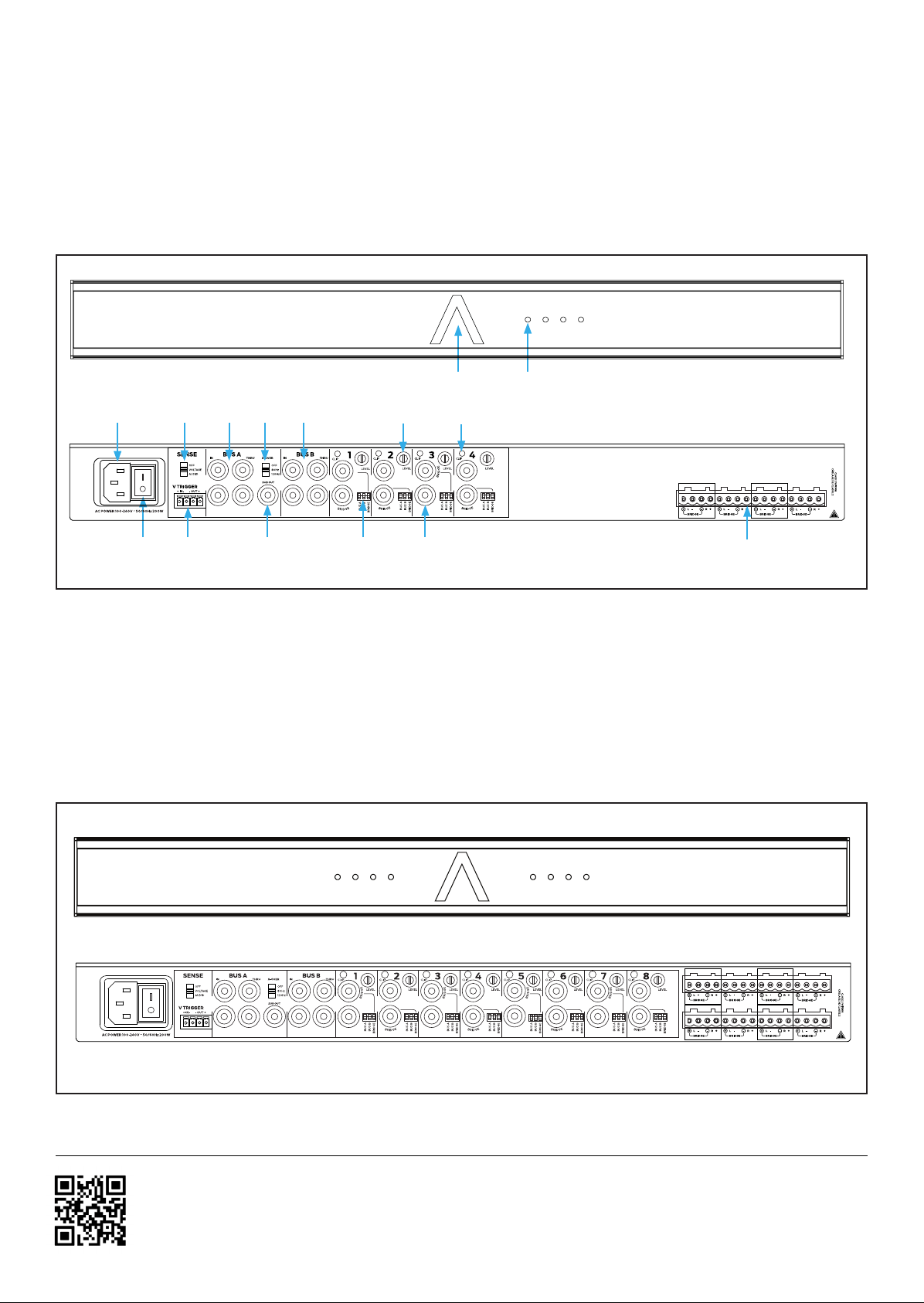
Sonance 8-50 MULTI-Channel Amplifier
FRONT PANEL
1. System Status Indicator
2. Zone Status Indicator
REAR PANEL
3. AC Power Socket
4. AC Power Switch
5. Sense Switch
6. Voltage Trigger Connector
7. Bus A Input / Thru
8. Crossover Switch (Bus A)
9. Sub Out (Bus A)
10. Bus B Input / Thru
11. Zone Configuration DIP Switch
12. Zone Level Control
13. Zone Speaker Outputs
14. Zone Local Inputs
15. Zone Clip Indicator
1
64
2
5
1 2 3 4
8-50
ZONE 1 ZONE 2 ZONE 4ZONE 3
3
9
8 10
13
11 14
12 157
Scan QR code for additional information.
For technical support call 949.492.7777
or visit www.sonance.com
IMPORTANT: DO NOT PLUG THE
POWER CORD INTO THE OUTLET
UNTIL ALL SYSTEM CONNECTIONS
HAVE BEEN MADE.
©2022 Sonance. All rights reserved. Sonance is a registered trademark of
Dana Innovations. Due to continuous product improvement, all features and
specifications are subject to change without notice. For the latest Sonance product
specification information visit our website: www.sonance.com
SONANCE • 991 Calle Amanecer • San Clemente, CA 92673 • (949) 492-7777
07.22.2022
Rear Panel
Front Panel
LED STATUS INDICATORS
Front Panel System Status Indicator
• White: Amp has power and is in Standby mode
• Blue: Amp has power and is Active
• Red: Amp is in protect mode. Power cycle
amplifier to reset, check all connections
Front Panel Zone Indicators
• White: Amp channel is on, no audio present
• Blue: Amp channel is on, audio present
• Red: Amp channel in protect mode. Power cycle
amplifier to reset, check all connections
• Yellow: Clipping amplifier output
Rear Panel Clip Indicators
• Red: Zone Signal is too high, clipping amp output.
Resolve by lowering source input signal or volume
Sonance 16-50 MULTI-Channel Amplifier
ZONE 1 ZONE 2 ZONE 4ZONE 3
ZONE 5 ZONE 6 ZONE 8ZONE 7
Rear Panel
Front Panel
