
MULTI-CHANNEL POWER AMPLIFIER
16-50 | 8-50
INSTALLATION AND SUPPORT MANUAL
2
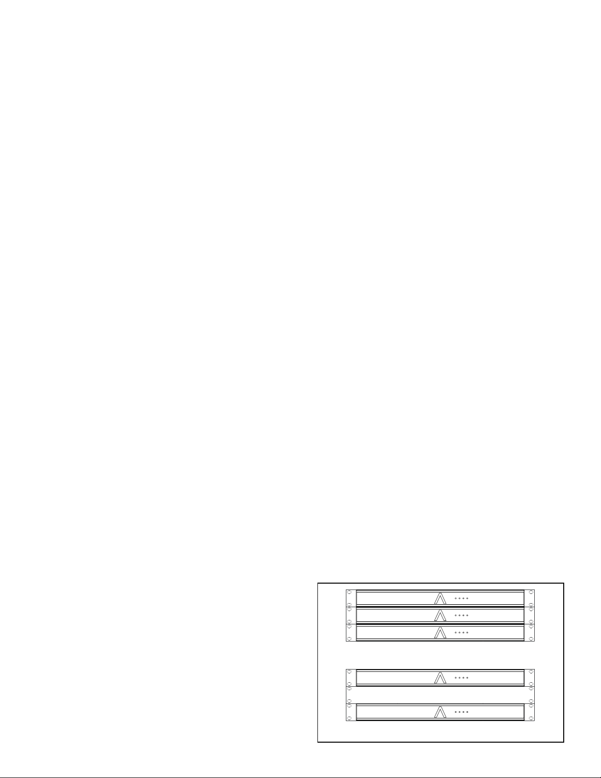
ZONE 1 ZONE 2 ZONE 4ZONE 3
ZONE 1 ZONE 2 ZONE 4ZONE 3
ZONE 5 ZONE 6 ZONE 8ZONE 7
SONANCE 16-50 | 8-50 AMPLIFIER
2 Box Contents
2 Introduction
2 Important Safety Information
3 Product Description
3 Placement
3 Quickstart Quide
4 Unpacking and Record Keeping
5 Recommended Tools, Cables, and Wires
5 Instruction Manual
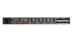
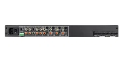
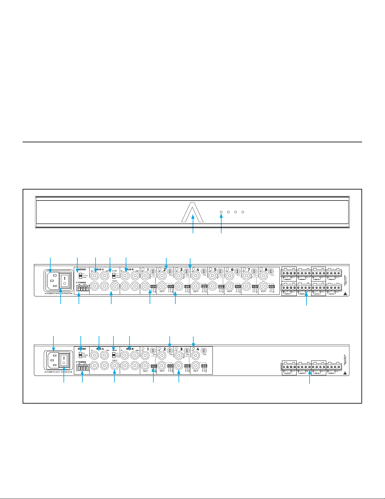
5 Front and Rear Panel Features
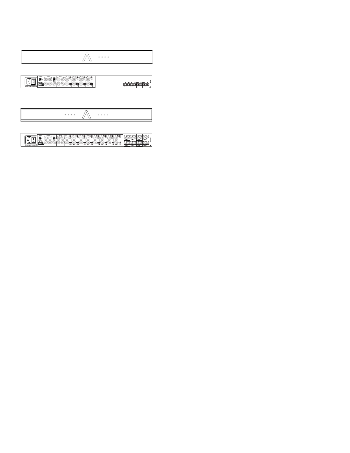
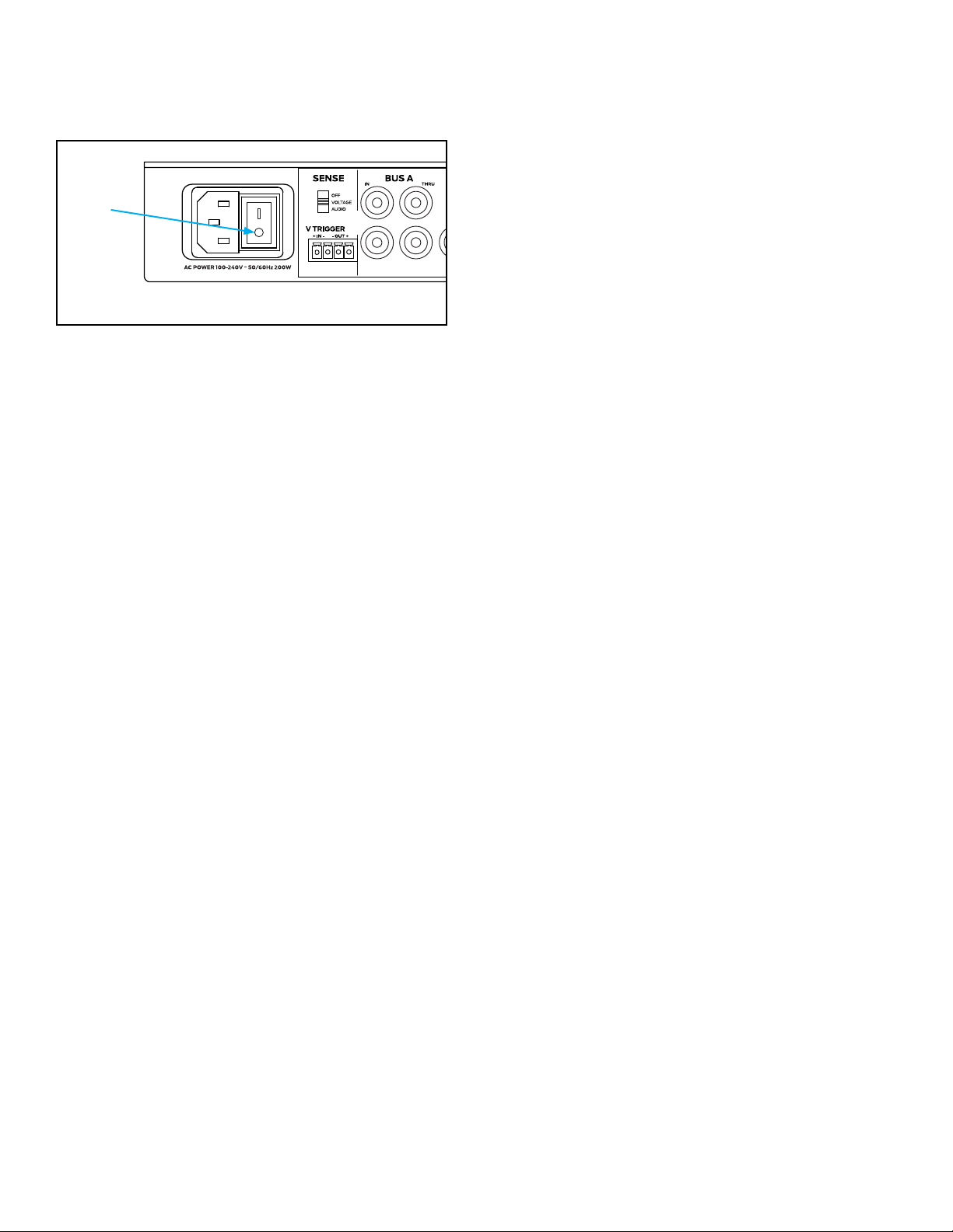
6 AC Power Socket and Trigger Mode
6 Line Inputs/Loop Outputs
8 Speaker Connections
8 Bridging Channels
9 Protecting Circuitry, LEDs, and Speakers
10 Shelf and Rack Mounting
10 Installation
11 Troubleshooting
15 Uninstalling for Relocation or Service
16 Replacement Accessory Parts
17 Warranty Statement
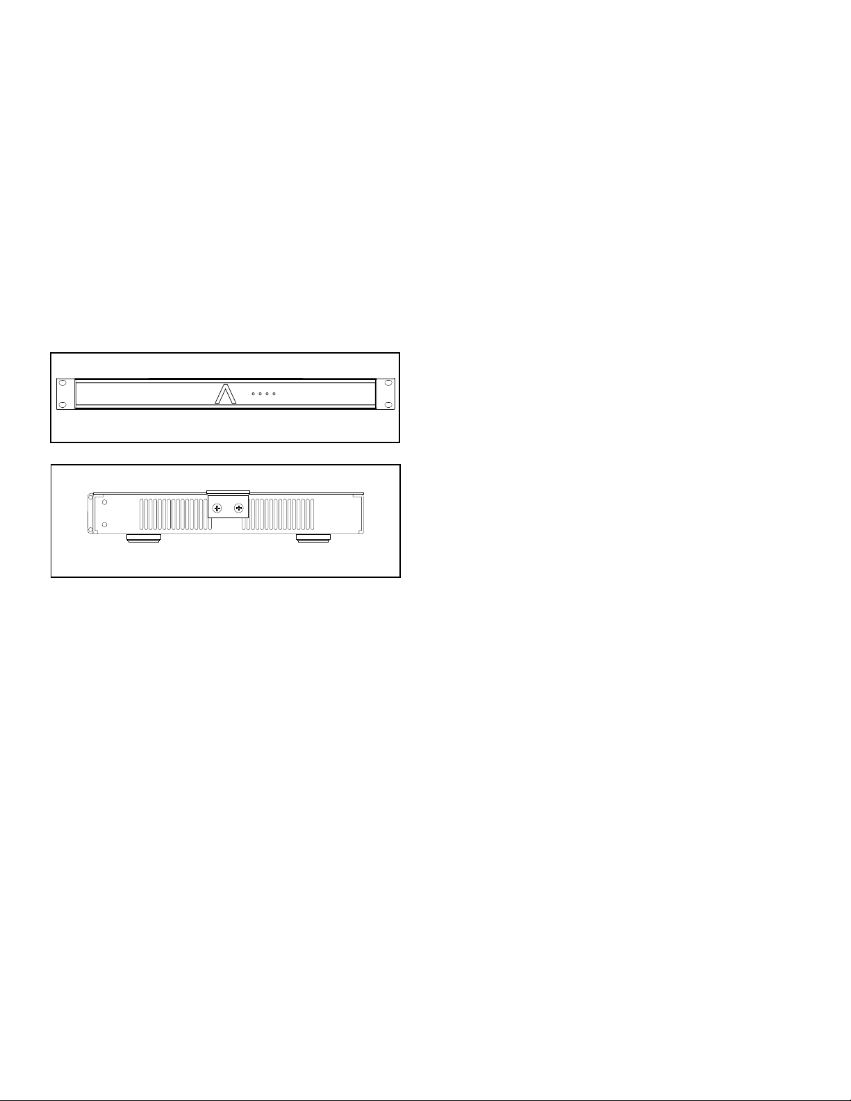
8-50 FRONT
(1) Quickstart Guide
(1) AC Power Cord (North America Units Only)
(4) Amp Feet
(2) Rack Ears
(4 or 8) Speaker Block Connectors
(1) Voltage Trigger Block Connector
1 2 3 4
8-50
Thank you for selecting the Sonance 16-50 or 8-50 multi-
Please take the time to carefully read through the
This extra time can lead to trouble free operation and
You should always follow these basic safety precautions
Read and retain instructions: Read all the safety and
Heed warnings: Adhere to all warnings and precautions
Carts and Stands: Use only with a cart or stand that is
6. CAUTION: TO PREVENT ELECTRIC SHOCK, DO NOT USE
THE POLARIZED PLUG WITH AN EXTENSION CORD,
RECEPTACLE, OR OTHER OUTLETS UNLESS THE BLADES
CAN BE FULLY INSERTED TO PREVENT BLADE EXPOSURE.
Grounding or Polarization: Precautions that should be
Power-Cord Protection: Route power supply cords so they
16-50 FRONT

3
Object Entry: Care should be taken so that objects do not
the enclosure is damaged, something has spilled into the
WARNING: THE POWER (MAINS) PLUG SERVES AS THE
AMPLIFIER’S DISCONNECT DEVICE. THE DISCONNECT DEVICE
SHALL REMAIN READILY OPERABLE DURING OPERATION.
TO ENSURE THAT THE DISCONNECT DEVICE IS EASILY
ACCESSIBLE, THE USER SHALL NOT PLACE THE AMPLIFIER IN
A CONFINED AREA DURING OPERATION.
Storms: To prevent damage to components, unplug all
WARNING: ANY CHANGES OR MODIFICATIONS TO THIS UNIT
NOT EXPRESSLY APPROVED BY THE PARTY RESPONSIBLE
FOR COMPLIANCE COULD VOID THE USER’S AUTHORITY TO
OPERATE THE EQUIPMENT.
NOTE: THIS EQUIPMENT HAS BEEN TESTED AND FOUND TO
COMPLY WITH THE LIMITS FOR A CLASS B DIGITAL DEVICE,
PURSUANT TO PART 15 OF THE FCC RULES. THESE LIMITS ARE
DESIGNED TO PROVIDE REASONABLE PROTECTION AGAINST
HARMFUL INTERFERENCE IN A RESIDENTIAL INSTALLATION.
THIS EQUIPMENT GENERATES, USES AND CAN RADIATE
RADIO FREQUENCY ENERGY AND, IF NOT INSTALLED
AND USED IN ACCORDANCE WITH THE INSTRUCTIONS,
MAY CAUSE HARMFUL INTERFERENCE TO RADIO
COMMUNICATIONS. HOWEVER, THERE IS NO GUARANTEE
THAT INTERFERENCE WILL NOT OCCUR IN A PARTICULAR
INSTALLATION. IF THIS EQUIPMENT DOES CAUSE HARMFUL
INTERFERENCE TO RADIO OR TELEVISION RECEPTION,
WHICH CAN BE DETERMINED BY TURNING THE EQUIPMENT
OFF AND ON, THE USER IS ENCOURAGED TO TRY TO CORRECT
THE INTERFERENCE BY ONE OR MORE OF THE FOLLOWING
MEASURES:
different
The Sonance 16-50 (16-channel power) and 8-50
channel into 8 Ohm loads, 100W per channel into 4
Ohm loads and 200W per bridged pair of channels into
operation and can pass paging and doorbell chimes
Bridged operation is useful for higher power output
applications such as driving a passive subwoofer or an
inputs for individual use or into one of the Bus Inputs
Assignment DIP
Assignment DIP switches to ON to allow for multiple
inputs to play together such as with use of paging or
8-50 has a comprehensive protection circuit that guards
against shorted outputs, over-current, over-temperature,
The 16-50 and 8-50 features fan assisted cooling utilizing
is completely isolated from temperature extremes, rain,
damage such as from condensation is not covered by
The Quickstart Guide is intended for the installer who
is familiar with the 16-50 or 8-50 and has reviewed
4
Save the box and its interior packing material in a
The information below is critically important for warranty
S/N: ___________________________________________
DATE OF SALE:__________________________________
DEALER NAME:_________________________________
CONTACT INFO:_________________________________
For high output applications, provide at least 1U space
The 16-50 and 8-50 were designed to be ultra-simple
detected, the unit will produce sound after approximately
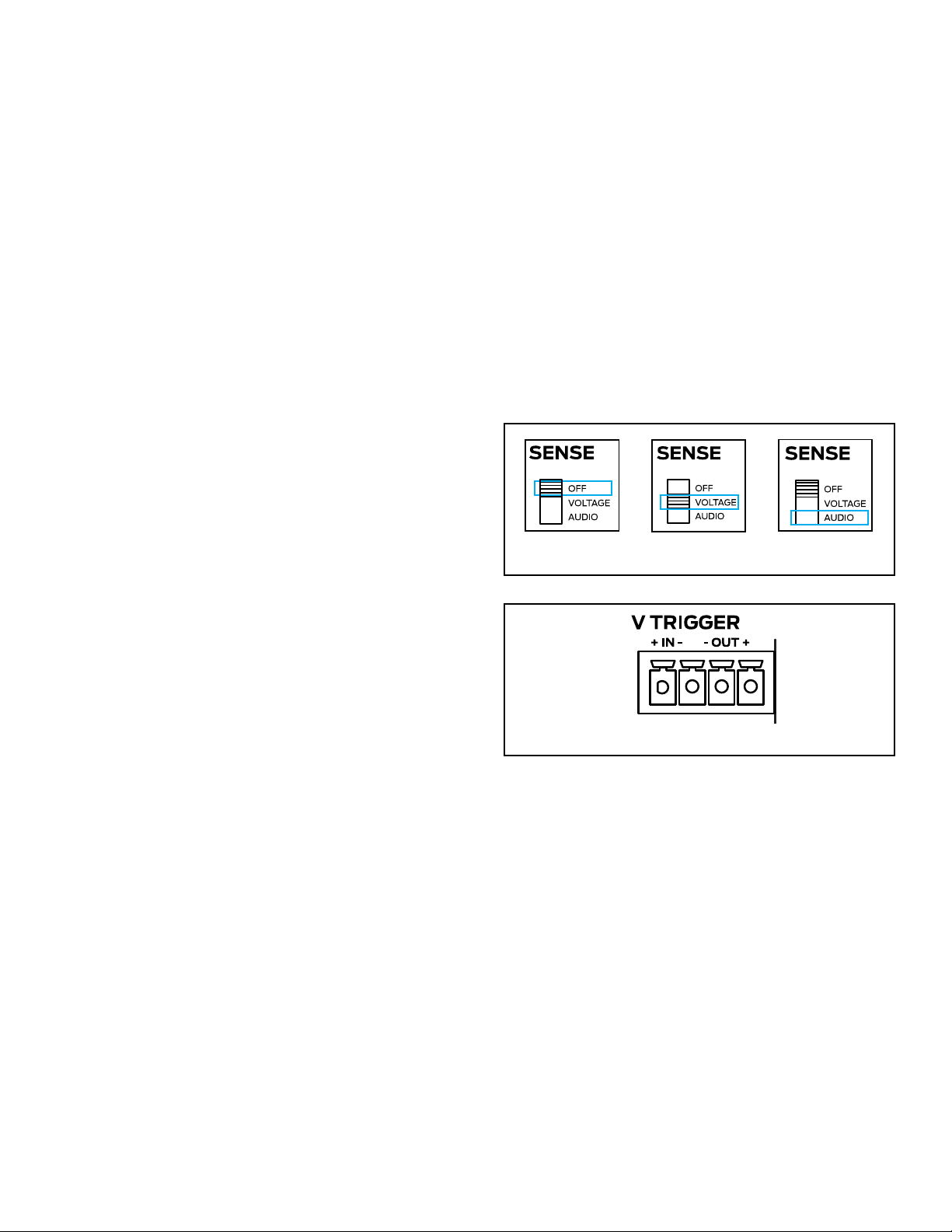
Decide on the appropriate Power Sensing Mode:
Voltage, Audio Signals or the “always on” OFF position
Set the Sense DIP
If using the voltage trigger feature, connect a two-
conductor wire from the 12 volt output of a zone
Connect a pair of RCA cables from the single source
Set the channel Input Assignment DIP switches to
Connect speaker wire from the speakers to their
With the volume on the source turned down to a low,
Follow the steps in the chapter entitled, ‘Protecting
Application Two
Four analog audio sources, such as four music streamers
or four line-level outputs of a multi-zone preamp into the
Decide on the appropriate Power Sensing Mode:
Voltage, Audio SOFF position
ZONE 1 ZONE 2 ZONE 4ZONE 3
Application One
One Analog audio source, such as a music streamer, into
the Bus A inputs for internal distribution to all eight (16-
Figure 1: Single Audio Source
OFF
Set the Sense DIP
If using the voltage trigger feature, connect a two-
conductor wire from the 12 volt output of a zone
Connect a pair of RCA cables from each stereo
Connect 14/4 speaker wire from the remote zones to
With the source volume turned down to a low,
Follow the steps in the chapter entitled, ‘Protecting
5
ZONE 1 ZONE 2 ZONE 4ZONE 3
ZONE 5 ZONE 6 ZONE 8ZONE 7
ZONE 1 ZONE 2 ZONE 4ZONE 3
• Stereo Line-Level RCA Interconnect Cable
• (1) Two or four conductor speaker wire relative to the
application
• (2) Two-conductor speaker wire is also acceptable
64
5
1 2
1 2 3 4
8-50
3
9
8
10
13
11 14
12 157
• Phillips #2 screwdriver
• Speaker wire strippers
• Self-adhesive wire labels
64
53
9
8
10
13
11 14
12 157
6
System Status Indicator (Beam Logo)
White: System is powered and in standby
Blue: System is powered and ready/active
Flashing Red: System fault, over temperature fault
OFF: System is off and not powered
NOTE: UPON INITIAL POWER UP, THE SYSTEM WILL UNDERGO
A BOOT PROCESS THAT MAY LAST A FEW SECONDS. NO
AUDIO WILL BE HEARD.
Zone Status Indicators
OFF: zone is not active (system is off or in standby)
too small to be detected
BLUE: zone is active and detects an input signal
FLASHING YELLOW: zone is active but is overdriven
RED: zone is in protection
The 16-50 and 8-50 feature a removable IEC power
rear panel and plug the male end into a grounded
into a convenience outlet on any other audio or video
only a heavy duty (14 gauge or larger) extension cord to
turn ON when it receives an audio signal, when it receives
a control voltage from an external source, or to remain on
NOTE: IF EITHER AUDIO OR VOLTAGE TRIGGERS ARE
SELECTED, THE AMPLIFIER HAS A LESS THAN ONE SECOND
CYCLE TIME FROM STANDBY TO PLAY AN AUDIO SIGNAL. THIS
IS NORMAL AND REQUIRED TO COMPLY WITH THE EU <O.5
WATT ERP DIRECTIVE. SELECT OFF TO BYPASS THIS FEATURE.
SEE POWER CONSUMPTION TABLE FOR IDLE POWER USE.
Auto On Triggering - Three Position Switch
AUDIO -
turn ON when the minimum audio signal of 1mV is
VOLTAGE - When the Sense switch is set to voltage, the
to the input of the V Trigger using the left side of the
Connect a two-conductor wire from the 12 volt output of
connections are typically used with a multi-zone preamp
BUS A and BUS B
To share one or two audio sources internally with more
blending auxiliary sources together, such as for paging
announcements and door chimes along with the audio
and doorbell chimes cannot mute the local audio source
Figure 3: V Trigger
3
1
ZONE 1 ZONE 2 ZONE 4ZONE 3
3
1
ZONE 1 ZONE 2 ZONE 4ZONE 3
OFF - When the Sense switch is in the top OFF position,
NOTE: WHEN THE AUTO ON SWITCH IS SET TO OFF THE
AMPLIFIERS POWER SAVING FEATURE WILL BE DISABLED.
12V Trigger Output - The Sonance amp has a 12V Output
two wire screw connector found on the right side of the
green block connector that provides 12V DC whenever
be always on without any delay between signal input
Voltage Sensing: Optimum sensing option as it is
Audio Sensing: Simple option that controls the on/off
7
There are three options when connecting audio inputs
to the amplier:
Zone Line In Connectors: Use the local inputs to
dedicate one audio source to its corresponding zone
Bus A Input: Use the Bus A input to pass an
additional audio source, such as paging to any of the
Bus B Input: Use Bus B input to pass an additional
audio source, such as door chimes to any of the
BUS THRU Outputs
Each of the Bus Inputs provide non-buffered loop
connected in series will depend on the output capability
and RIGHT IN connections passes through to the LEFT
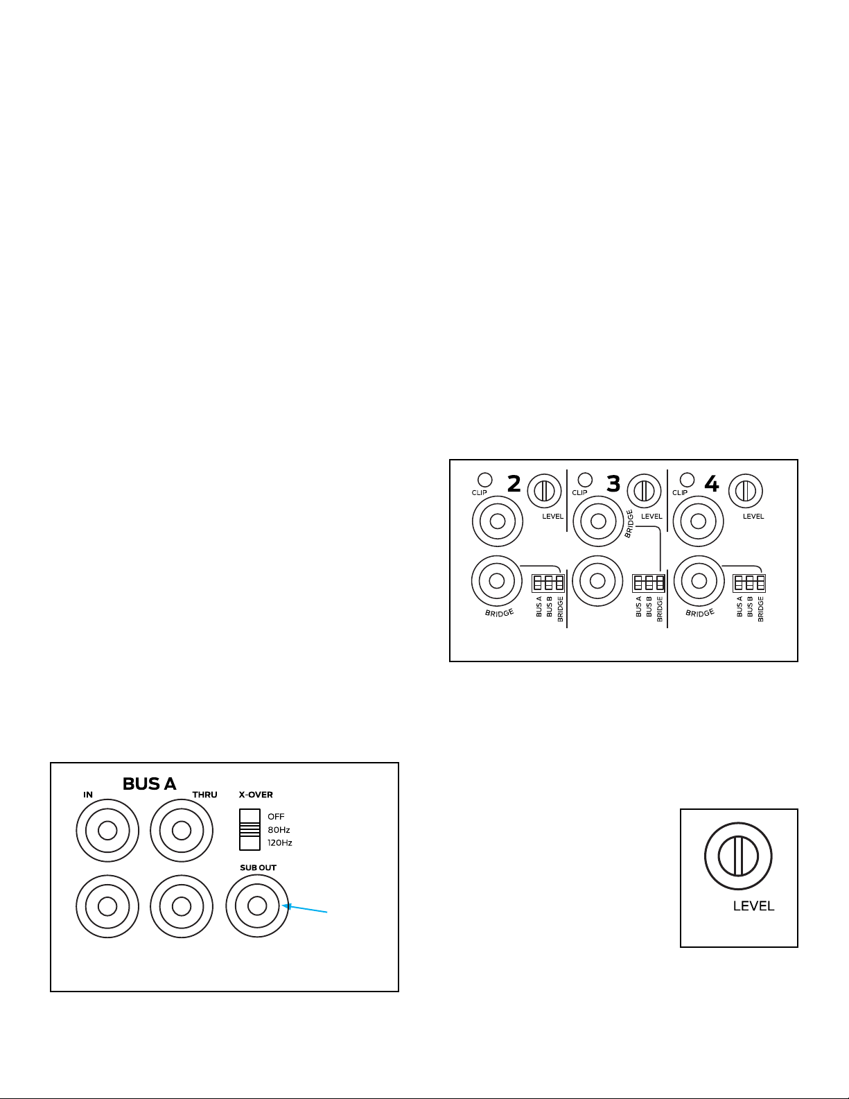
BUS A SUB Out
BUS A has subwoofer output connection, which sums
Setting the X-OVER switch to 80Hz or 120Hz will apply a
The 80Hz setting is the proper setting for most
subwoofer applications when used with large and
used with smaller main speakers or when more bass is
Connect a stereo line-level source with an RCA cable
Connect a single RCA cable from the SUB OUT jack
to the line-level input on a powered subwoofer, such
Figure 4: Using the Subwoofer Line-Level Output with the
Bus A Inputs (not applicable with the Bus B or local inputs)
SUB OUT
is being used in bridged mode (8 ohms minimum), use
the Zone IN connection labelled “BRIDGE” as described
Input DIP Switch Assignments
The DIP switches enable one or more audio sources to be
played through one or more speaker outputs
to the local (direct) source, Bus A signal input and/or Bus
DIP switch to ‘ON
Two zone example, the home could be subdivided into
into Bus A and a second source into Bus B (not into the
DIP switches
Control system example, the input connections can all be
local for a discrete four zone system with Bus A switched
sources connected to the various inoputs and the DIP
3
1
ZONE 1 ZONE 2 ZONE 4ZONE 3
Figure 5: Input DIP Switches
3
1
ZONE 1 ZONE 2 ZONE 4ZONE 3
Zone Trim Controls
is a TRIM control, not a volume knob, so the minimum
gain setting (fully counter-clockwise) will not turn off
Figure 6:
Volume Control
speakers distort, thereby preventing
controls also allow balancing of
the sound levels of different zones
or the outputs of the right and left
channels to compensate for various
room characteristics or seating
3
1
ZONE 1 ZONE 2 ZONE 4ZONE 3
IMPORTANT: DO NOT COMBINE NEGATIVE TERMINALS. THE
AMP IS NOT COMMON GROUND TYPE ARCHITECTURE.
8
AMPLIFIERS POWER REQUIREMENTS:
8-50 100-120VAC Max Power All Channels 8 ohm or 4 ohm 600W 3 (120VAC) 4
(120VAC)
1/8 Power All Channels <200W 9 (120VAC) 12 (120VAC)
@ Idle 30W
8-50 220-240VAC Max Power All Channels 8 ohm or 4 ohm 600W 6 (230VAC) 8
(230VAC)
1/8 Power All Channels <200W 18 (230VAC) 24 (230VAC)
@ Idle 30W
16-50 100-120VAC Max Power All Channels 8 ohm or 4 ohm 600W 3 (120VAC) 4
(120VAC)
1/8 Power All Channels <200W 9 (120VAC) 12 (120VAC)
@ Idle 50W
16-50 220-240VAC Max Power All Channels 8 ohm or 4 ohm 600W 6 (230VAC) 8
(230VAC)
1/8 Power All Channels <200W 18 (230VAC) 24 (230VAC)
@ Idle 50W
NOTE: THE AMPLIFIERS DO NOT SUPPORT MATRIX VOLUME
CONTROL. RELATIVE SOURCE LEVELS BETWEEN ZONES AND
ZONE/BUS INPUTS MUST BE SET AT THE SIGNAL SOURCE.
IMPORTANT: USE CAUTION WHEN SETTING VOLUME LEVELS
EITHER ON THE AMPLIFIER OR AN AUDIO SWITCHER AS NOT
TO OVERDRIVE AND POSSIBLY DAMAGE SPEAKERS. VERIFY
ALL SOURCES AS OUTPUT VOLTAGE VARIES FROM DEVICE TO
DEVICE.
Figure 8:
Speaker Connectors
The removable Speaker Block
Connectors used on the
bare wires are in contact with
have four terminals actuated by
can be used for normal stereo or
NOTE: ALWAYS CHECK LOCAL BUILDING CODES BEFORE
INSTALLING WIRE IN WALLS OR CEILINGS.
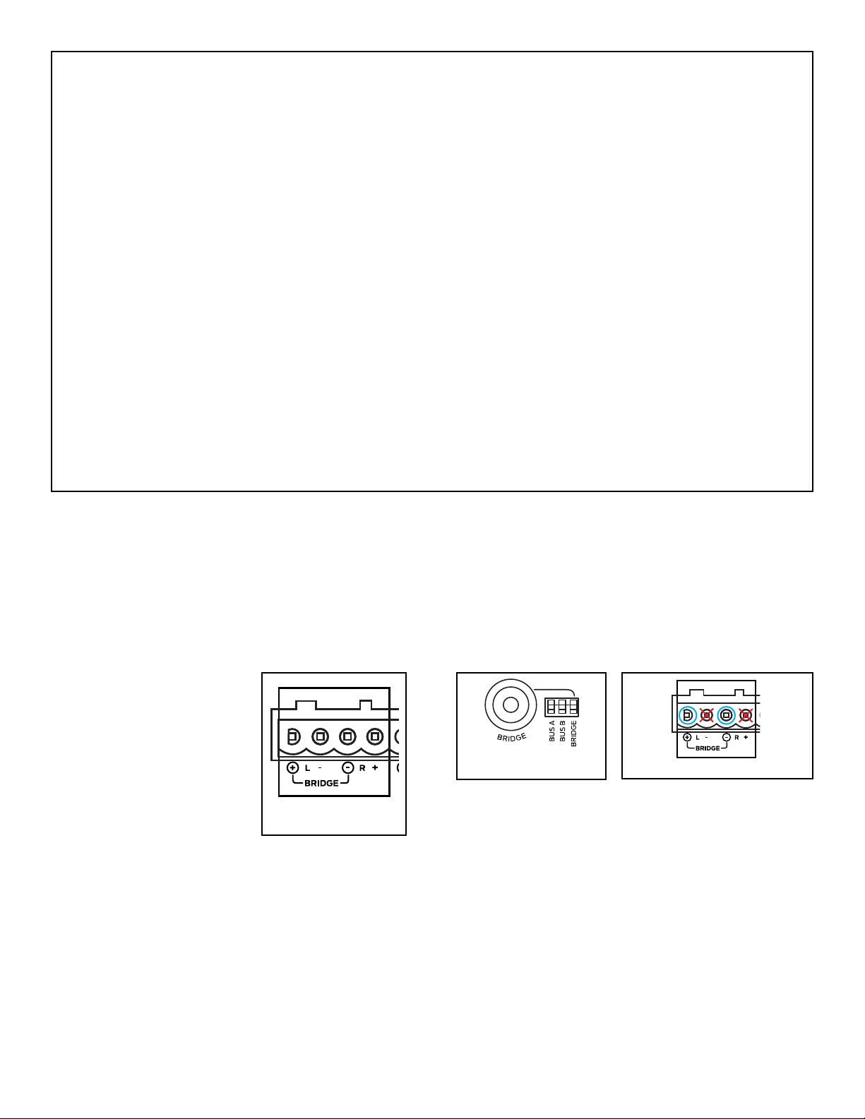
IMPORTANT: THE MINIMUM SPEAKER IMPEDANCE FOR
BRIDGED OPERATION IS 8 OHMS. DO NOT CONNECT
SPEAKERS RATED AT LESS THAN 8 OHMS IN BRIDGED MODE.
THE AMPLIFIER CAN RUN HOT, MAY GO INTO PROTECTION
AND HAVE A REDUCED LIFESPAN.
Bridge Mode/Bridging
the phase to the right channel and drives the left and
3
1
ZONE 1
ZONE 2 ZONE 4ZONE 3
right channels together in series to generate higher
additional power in bridge mode can be advantageous
for driving a passive woofer such as the Visual
Performance VP85RW or an 8 Ohm outdoor satellite and
3
1
ZONE 1
ZONE 2 ZONE 4ZONE 3
Figure 10: Bridging Channels
Figure 9:
Bridging Channels
For bridging, use the left Local Input or the left Bus Input
Use the DIP switch to select the input you would like to
connector marked “-” (third speaker lead position
3
1
ZONE 1 ZONE 2 ZONE 4ZONE 3
9
Zone Speaker Outputs
The removable block connectors used on the Sonance
Follow the connection layout on the rear panel of the
should be on the left side connection and the negative
Amplier Channel Protection
If a channel encounters a short circuit or extremely low
impedance, it will cause the affected channel outputs to
Only the effected channels output will mute, all other
Amplier Channel Protection Indication
indicators that illuminate to indicate the current
IMPORTANT: DO NOT EXCEED 100MA OF CURRENT DRAW.
DAMAGE CAN OCCUR.
Indicator color/status:
Red = Zone protection
Yellow Flashing = Zone overdriven
Blue = Normal status with signal detected
White = Normal status with no signal detected
Off = No power/standby
IMPORTANT: ALLOWING THE AMPLIFIER TO OPERATE WITH
ONE OR MORE CHANNELS IN PROTECT MODE FOR AN
EXTENDED TIME CAN DAMAGE THE AMPLIFIER.
Amplier Over Temperature Protection
If the power supply heat sink temperature exceeds the
design maximum, the protection circuit will activate,
IMPORTANT: ANY TIME THE PROTECTION CIRCUITS ARE
TRIGGERED, UNPLUG THE AMPLIFIER’S POWER CORD FROM
THE WALL OUTLET BEFORE TROUBLESHOOTING.
This can be accomplished by reducing the output volume
note the Sonance speaker warranty does not cover
to adjust the output level controls before playing the
speakers to protect them following the instructions
Select two or three challenging music selections that
Choose dynamic tracks with substantial bass impact
is best to use uncompressed, high-resolution music,
Reduce all zone output volume level controls on the
Turn the zone preamp or a source with variable
Play your other challenging music tracks and ensure
of distortion is heard, decrease the volume setting
beyond these settings can damage the speakers and
There is a limit of how loud an audio system will play
with the feet removed for use in low to moderate
is recommended to leave at least 1U space between
10
If shelf mounting, attach the four included feet by
screwing them into the threaded openings, no tool is
Installation Steps With A Single Audio Source
Once mounted in a rack or on a sturdy shelf, make
Decide on the appropriate Power Sensing Mode:
Set the Sense DIP
If using the voltage trigger feature, connect a two-
conductor wire from the 12 volt output of a zone
Connect a pair of RCA cables from the single source
Set the Input Assignment DIP switches to the Bus A
inputs, alternating between left channel and right
If using the Bus Inputs along with a passive woofer/
subwoofer (ex: VP85RW) in a zone, connect a single
See section ‘Using The Subwoofer Line-Level Output
Connect 14/4 speaker wire from the remote zones to
their dedicated Speaker Output Block Connector on
With the source volume turned down to a low,
Follow the steps in the chapter entitled, ‘Protecting
Figure 12: Rack Ear Front Mounting 8-50
SIDE VIEW RIGHT
FRONT VIEW
head screws found on each side of the left and right
Rack Ear Conguration Options
accept mounting of the ears in the designated locations:
Front: Standard rack mounting
Middle Up: Under side mounting applications
After mounted in a rack or on a sturdy shelf, make
Decide on the appropriate Power Sensing Mode:
Set the Sense DIP
If using the voltage trigger feature, connect a two-
conductor wire from the 12 volt output of a zone
Connect a pair of RCA cables from each stereo
Set the Input Assignment DIP
paging or door chimes are not used, proceed to step
If providing doorbell chimes and/or paging into the
also providing paging, run a line level cable from
DIP switches to
DIP switch setting will
If using the Bus Input source along with a passive
woofer/subwoofer (ex: VP85RW) in a zone, connect a
driving the woofer does not have to perform this
Connect 14/4 speaker wire from the remote zones to
For example, if the audio source for the kitchen is
connected into channels one Left and one Right RCA
Figure 13: Rack Ear Middle Up Mounting 8-50

11
inputs, then connect the 14/4 speaker wire from the
kitchen speakers into the Speaker Block Connector
With the source volume turned down to a low,
Follow the steps in the chapter entitled, ‘Protecting
Recommended Troubleshooting Tools
•
•
•
• A short run of 14/2 or 14/4 speaker wire to connect the
•
• Optional multimeter to read short circuits, open
circuits and to take speaker resistance and continuity
The measurement will be across the two-conductor
working with a four-conductor wire, then test one set of
PLEASE NOTE: A SPEAKER WITH A SWITCHABLE HIGH-
PASS FILTER IN THE CROSSOVER, SUCH AS AN AS38R/S
OR VP38R/S, WILL NEED TO HAVE THE SWITCH IN THE
OFF POSITION TO TAKE A DCR READING. OTHERWISE, THE
CAPACITOR IN THE HIGH PASS FILTER WILL BLOCK THE DC
SENT FROM THE METER AND THE LOAD WILL SHOW ‘OPEN’.
REMEMBER TO SET THE HIGH PASS FILTER SWITCH BACK TO
ON AFTER TAKING THE DCR READING.
Disconnect the speaker wires from the Speaker
Set multimeter to measure DC, apply the meter
probes across the two-conductor speaker wire for
If the meter reads ‘INFINITE
is open (cut) somewhere between the amp and the
speaker, the speaker is not physically connected
to both wires or the speaker has become severely
compromised (open/blown voice coil from excessive
If the DC measurement is zero or close to zero, then
the circuit (wire and speaker) has become shorted
across the speaker wires or the speakers have been
severely damaged by excessive power or over-
If the DC measurement is between 6-8 Ohms (for a
single 8 Ohm speaker), then the circuit has continuity
A speaker from the zone can also be tested directly
Potential Reasons
•
• The AC outlet is connected to is not active or its
GFCI circuit has been tripped (Ground Fault Circuit
• The power switch on the rear panel is set to the
The 16-50 and 8-50 are shipped with the Power Sense
a live AC outlet and the rear panel power switch is
Steps to Resolve
illuminate:
Ensure the detachable AC cord connector is fully
appliance such as a lamp into the same AC outlet as
be reset or the outlet otherwise evaluated for proper
Remove the amp and take it to another location in

12
illuminate with all these steps, then please
purchased from or Sonance Technical Support:
Applicable to one or both paired channels, such
component providing line-level audio into the 8-50, such
as the second zone outputs on an AV receiver, a pair of
zone outputs of a multi-zone controller, music server,
Potential Reasons:
• A fault in the interconnect cable between the source
• RCA cables are plugged into the input on the source
•
• A fault in the speaker wire and/or its connections,
either at the Speaker Block Connector at the back of
•
• The DIP switches for the audio input selection are set
•
•
output to the speakers and the protection LEDs on the
If the protection LEDs are illuminated, proceed to step 6
IMPORTANT: BEFORE DISCONNECTING OR RECONNECTING
AUDIO CABLES OR SPEAKER CONNECTIONS, TURN
THEAMPLIFIER OFF. ONCE THE CONNECTIONS ARE REMADE,
THEN TURN THE AMP BACK ON. MAKING OR BREAKING LINE-
LEVEL RCA CONNECTIONS WITH THE AMPLIFIER POWERED
ON CAN DAMAGE THE AMPLIFIER AND/OR THE SPEAKERS.
Steps to Resolve
Check the line-level RCA interconnect cable and
Make sure the RCA plugs are pushed all the way into
cable or temporarily use one of the RCA cables from
Try the output of another source into the non-
Potential Reasons
• The most common reason is one speaker pairs is
positive, left channel negative, right channel positive
positive uses the red conductor, right channel
negative uses the black conductor, left channel
positive uses the white conductor and left channel
outputs of a second zone of an AV receiver, try the
zone 3 output or the variable output of a music
Examine the speaker wires inserted into the Speaker
into the connector without breaks, the wires being
loose or strands touching? Re-secure any suspect
wires, plug the connector back into the amp, turn the
Using a short run of speaker wire, connect a local
block connect back into the amp, turn the amp
is now producing audio, then there could be an
An alternative is to disconnect the Speaker Block
Connector from a known working zone and plug it
produce sound? If yes, then the wiring between the
an internal fault that for whatever reason is not
If the front panel zone LEDs are illuminated red,
If the protection LEDs remain on with the Block
the block connector is unplugged, then try step 4
yes, then there could be a short in the speaker wires
leading to the remote zone or the speakers have

13
Steps to Resolve
wire connected to the right channel positive and the
red wire connected to the right channel negative,
do voices seem to emanate somewhere between
the speakers? If yes, then you have solved the polarity
the speakers are inaccessible and reversing their wire
polarity is impractical, then reversing the polarity at
If the wire/speaker polarity is not the issue, ensure
the line-level input signals are full-range and not
local full-range source to the left and right inputs on
With a second, known working source in place, do
the speakers now have full-range sound? If yes,
then the preamp supplying the audio signal to
If the speakers still do not have much bass output,
connect a different, properly working pair of test
local test speakers have good bass? If so, then the
speakers in that zone will need to be uninstalled and
tested separately; replace one or both speakers as
Potential Reasons
• The source providing the audio signal into the
•
of these four connections are reversed at either the
be moving outward while the other speaker will be
• The speakers are supplied with a high-passed signal
• One or both of the woofers in the speakers have an
• The volume controls on the back panel of the
Steps to Resolve
Determine the voltage output rating of the source
such as music-servers, CD players and tuners have
source is rated for the same output voltage as the
output voltage of the source is below the input
sensitivity rating, then a preamp will need to inserted
Check the volume control setting on the source
Increase the volume output on the source if its
Check the setting of the volume controls on the back
but below the point they cause distortion in the
volume controls is to protect the speakers from
Potential Reasons
•
• The source is providing too high of an output signal
•
• The speaker wire has been shorted somewhere
•
•
Steps to Resolve
Check the Speaker Block Connectors to ensure wire
strands from adjacent connections are not touching
and securely inserted into the Speaker Block
normally trigger the protection circuitry and mute
sure the speaker impedance is 4 Ohms and above for
Substitute another, known working RCA cable

14
Substitute a different, known working source
controls to prevent overdriving the speakers before
Test the speakers with a different, distortion free
the distortion remains, then the speakers are likely
the replacement speakers, please review the chapter
entitled, ‘Protecting Speakers From Becoming
Disconnect the Speaker Block Connector, loosen
the screws, remove the speaker wires and substitute
have distortion, then the problem is in the wiring
If the connections on the Speaker Block Connector
are correct, both channels of the RCA cable are
working and distortion free, the source into the amp
is not distorted but the local test speaker is distorted,
Potential Reasons
• The introduction of a satellite receiver or cable box
into the audio system can cause a ground loop,
• The speaker or the speaker wires are in very close
proximity to the transformer in the low voltage
•
Steps to Resolve
Temporarily reduce the audio system to a bare
connected to an audio system with an AV receiver,
cable box and/or satellite receiver, then turn off the
With all the line-level inputs disconnected, is the
hum still audible through the speakers? If yes and
not physically grounded to the rack, then the hum
Connect a mobile audio device using its headphone
output with a ‘stereo mini to two RCA male adaptor
streamer, or another audio source with a two prong
gone, then the problem is likely caused by a system
is with a ground loop isolator with RCA inputs and
If the hum is still present, consider temporarily
ground solves the problem, consider using an AC
hum eliminator/lifter on the component introducing
If any of the in-ceiling speakers are close to the low
voltage lighting transformers, then the speakers will
need to be moved, the transformers moved away
from the speakers or at least the crossovers on the
Potential Reasons
•
• Poorly shielded or defective line-level RCA cables
• Damaged speaker voice coils and/or suspension
components (torn spider and/or woofer surround)
• Drywall debris, insulation or other extraneous
material has fallen into the speaker and resting
• An improperly terminated two wire speaker
connection in which strands from one wire are in
•
Steps to Resolve
Connect a different, low noise audio source into
disappears, then the source has the noise and not

15
If the noise remains, ensure the RCA cables are good
Connect a pair of speakers from a different zone
Block Connector from the suspect channels on the
noise disappears, then the suspect zone speakers
Replace the damaged speaker(s) and set the volume
controls on the back panel below the point at which
‘Protecting Speakers From Becoming Blown/
If the noise is heard only from one zone or one
channel of a zone, connect a known working,
the noise remains, connect a test speaker to the
speaker? If yes, then the problem may be in the
remains and all the previous troubleshooting steps
have been performed, then the problem lies within
Potential Reasons
•
• The speaker wires are shorted either at the Speaker
Block Connector on the rear panel, somewhere
• The speakers have been damaged such that they
•
loads and above, which is one pair of 4 ohm
speakers, one pair of 6 ohm speakers or two pairs of
Steps to Resolve
place in a rack that has good circulation of fresh air
closed cabinet or closet with little ventilation as this
can trigger its thermal protection circuit and reduce
Disconnect the Speaker Block Connector from the
If the protection LEDs remain on, then this can
be caused by DC appearing on the RCA inputs or
different source from a pair of channels that are
the substitute speakers have sound, this indicates
a problem with the source such as DC and not the
Check the speaker wire for shorts, adjacent channel
wires touching each other, construction staples
accidentally driven through the speaker wire in a
and the speakers have sound, then there is a short
with the wire and/or speakers that were originally
If two pairs of speakers are connected to a pair of
impedance, then this may be triggering the
matching device between the amp channels and
the speakers, connect the additional speakers to
Pull out the removeable AC Power Plug from the AC
Disconnect all the RCA line-level cable inputs on the
If the removal is temporary, unplug the Speaker
screwdriver to loosen the speaker wire securing
screws on the Speaker Block Connector and remove
If the relocation is permanent, then re-insert the
Speaker Block Connector into the speaker outputs
If the unit is rack mounted, remove the rack mount
properly support its weight until all the rack screws
Store the rack mount screws and other
miscellaneous hardware in a resealable plastic
it in its original factory carton to keep it safe and
16
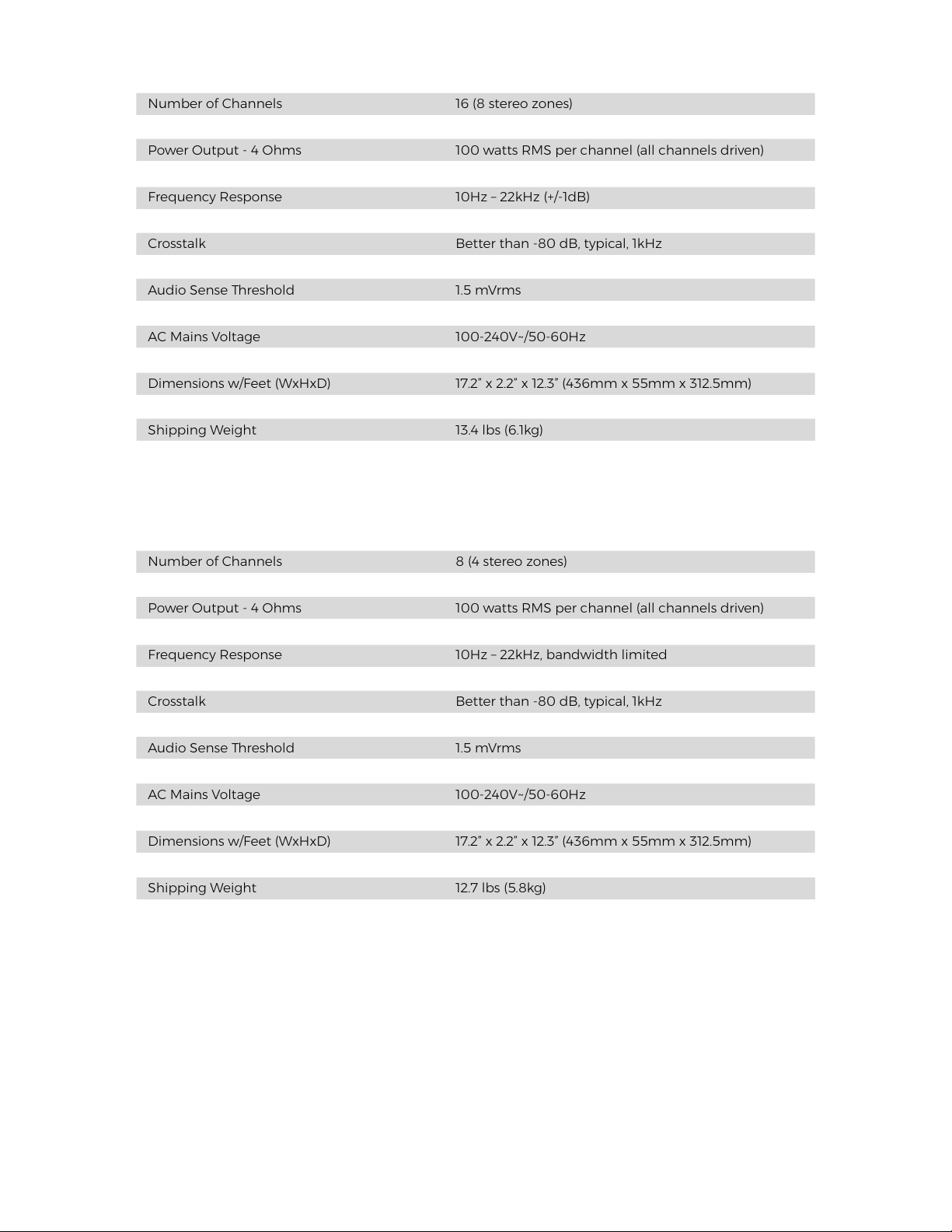
Number of Channels 8 (4 stereo zones)
Power Output - 8 Ohms 50 watts RMS per channel (all channels driven)
Power Output - 4 Ohms 100 watts RMS per channel (all channels driven)
Power Output - 8 Ohms (Bridged) 200 watts
Signal to Noise Ratio >100 dB A-wtd
Crosstalk Better than -80 dB, typical, 1kHz
Voltage Trigger Input 3-30Vdc
Crossover Filter OFF/80Hz/120Hz
AC Mains Voltage 100-240V~/50-60Hz
Number of Channels 16 (8 stereo zones)
Power Output - 8 Ohms 50 watts RMS per channel (all channels driven)
Power Output - 4 Ohms 100 watts RMS per channel (all channels driven)
Power Output - 8 Ohms (Bridged) 200 watts
Signal to Noise Ratio >100 dB A-wtd
Crosstalk Better than -80 dB, typical, 1kHz
Voltage Trigger Input 3-30Vdc
Crossover Filter OFF/80Hz/120Hz
AC Mains Voltage 100-240V~/50-60Hz
16-50 (North America Model): 93546
16-50 (International Model): 93547
8-50 (North America Model): 93544
8-50 (International Model): 93545
Amp Feet: 93558
Rack Ears: 93559
Speaker Block Connector: 144173
Voltage Trigger Block Connector: 144174
AC Cord: 600393
Contact Sonance Customer Service to order parts:

17
SONANCE • 991 Calle Amanecer • San Clemente, CA 92673 USA
PHONE: (949) 492-7777 • FAX: (949) 361-5151 • Technical Support: (949) 492-7777
its option and expense during the warranty period, either repair the defect or replace the Product with a new or remanufactured Product
Additional Limitations and Exclusions from Warranty Coverage: The warranty described above is non-transferable, applies only to the
initial installation of the Product, does not include installation of any repaired or replaced Product, does not include damage to allied or
Customer Service at (949) 492-7777 within the warranty period, must obtain a return merchandise number (RMA), and must deliver the
Product to Sonance shipping prepaid during the warranty period, together with the original sales receipt, or invoice or other satisfactory
Warranty Process: Please follow the troubleshooting instructions in this manual or work with your Sonance dealer to determine the exact
In order to initiate a warranty claim: