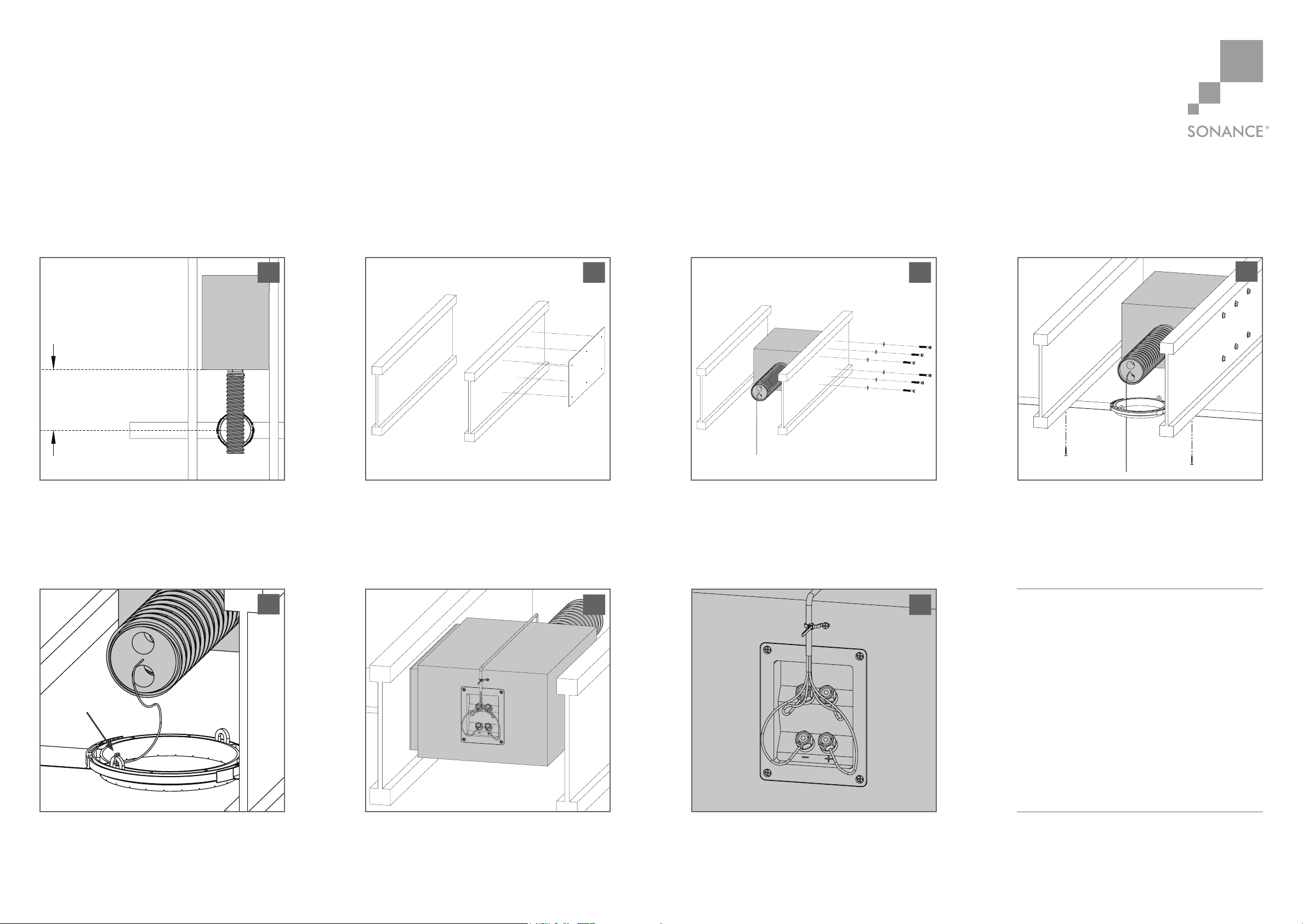
Determine the location for the flex bracket.
Ensure there is adequate room for the BPS8
subwoofer at the location of the flex bracket.
The speaker opening must be located within
12” (305mm) of the BPS8 to allow the port
tube to reach through the flex bracket.
Place the mounting template on the side of the
joist and drill six 1/2” (12.7mm) holes through
the joist at the locations shown on the mounting
template.
1 2
Hold the side of the BPS with the rubber
damping pad up against the side of the joist
and install the six lag screws and washers to
secure the BPS in place.
3
12” (305mm)
BPS8
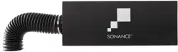
Port tube
Flex Bracket
Attach the flex bracket to the joists. The flex
bracket must be located within 12” (305mm)
of the BPS8 to allow the port tube to reach
through the flex bracket opening.
Loop tether into the flex bracket. Pull tether all
the way until port tube lies firmly on the flex
bracket. Tie tether into a knot. This process
ensures that other tradespersons won’t infringe
on port tube assembly area.
6 7
Bandpass subwoofer can be installed in
joists spaced 16” on center or greater.
©2014 Sonance. All rights reserved.
Sonance, Architectural Series and Visual Performance
are registered trademarks of Dana Innovations.
Due to continuous product improvement, all features
and specifications are subject to change without notice.
For the latest Sonance product specification
information, visit our website: www.sonance.com
SONANCE
212 Avenida Fabricante
San Clemente, CA 92672-7531 USA
(800) 582-7777 or (949) 492-7777
FAX: (949) 361-5151
Technical Support: (800) 582-0772
www.sonance.com
06.06.1433-5965
4
5
Tether into
flex bracket
loop
(1) Quickstart guide
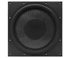
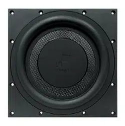
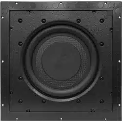
(1) Bandpass subwoofer w/ port tube
(1) Cardboard mounting template
Mounting screws & washers:
(6) 5/16” x 2” lag screws (for thinner beams)
(6) 5/16” x 3” lag screws (for thicker beams)
(6) 5/16” washers
Box Contents
BANDPASS STEREO SUBWOOFER QUICKSTART GUIDE
BPS8 FOR USE WITH VISUAL PERFORMANCE
®
BANDPASS CONNECTORS
Secure the wires to the included zip tie near the
terminals to prevent accidental removal by
another tradesperson.
Attach the four conductor wires from the amplifier to the input
terminals on the end of the BPS. Positive wires to red terminals and
negative wires to black terminals. Run the speakers wires to amplifier
location and run signal test with 9V battery. NOTE: Port tube contains
foam plug with tether, make sure pressure levels don’t expel the
foam and tether. Do not connect the voice coils in parallel.