
Loading ...
Loading ...
Loading ...
TRADITIONAL REACH-INS
TEC_TM_121 | REV. B | EN 07/14/2021 Page 7 of 22
truemfg.com
Installation (cont.)
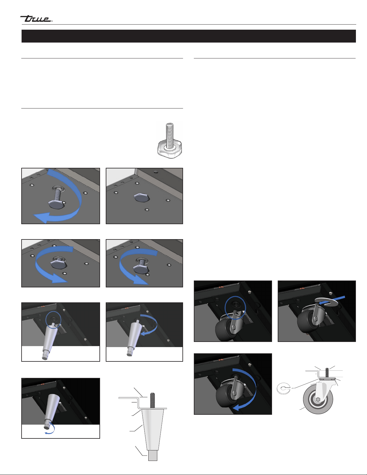
Installing 6" Leveling Legs or Castors
Adjustable legs will provide 6" (152 mm) of clearance under the
cabinet. Castors provide cabinet mobility.
NOTE: If the cabinet has a center leveling screw, castor, or leg,
make sure it is adjusted properly so it makes full contact with
the floor after the cabinet has been leveled.
Required Tools
Adjustable Wrench
6" Leveling Legs
1. Access the bottom of the cabinet and thread the leveling legs
into the rail. See figs. 3 and 4.
2. Verify that the cabinet is level.
3. If the cabinet is not level, gently lift and support the low end
of the cabinet. With an adjustable wrench, screw the bottom
stem of the leveling leg in or out to level and support the
cabinet. See fig. 5.
Castors
1. Loosen the castor bolt enough to slide the provided castor
shims between the castor bearing and the bottom rail of
the cabinet. See fig. 6.
2. Install the desired number of shims. If more than one shim is
used, turn the slots at a 90˚ angle to each other, so the slots do
not align. See figs. 7 and 8.
3. Tighten and secure the shims and castors with the optional
castor wrench. Lower the cabinet and verify that it is level. If
the cabinet is not level, repeat the process until the cabinet is
level and supported.
Fig. 1. Turn the leveling legs clockwise to lower the unit.
Cabinet Location
1. Ensure that the drain hose or hoses are positioned in the pan.
2. Free the plug and cord from inside the lower rear of the cooler
(DO NOT plug in).
3. Place the unit close enough to the electrical supply so that the
extension cords are never used.
Fig. 2. Turn the leveling legs counterclockwise to raise the unit.
Rail End
Snug Fit
Here
Leg
Lower Rail
Assembly
Bo
ttom Stem
Fig. 5. Turn the bottom stem to level the
cabinet.
Fig. 3. Locate the threaded hole in the
rail.
Fig. 4. Screw in the leveling legs.
Fig. 6. Loosen castor bolt.
Fig. 8. Position multiple shims at
90˚ angles.
Fig. 7. Install shim(s).
Leveling Shim
Lower Rail Assembly
Bearing Race
Snug Fit Here
Rail End
Castor
Castor Stem
Installing Standard Leveling Legs
Leveling legs are provided to assist with the leveling of the cabinet.
1. Access the bottom of the cabinet and locate the
leveling legs.
2. The leveling legs may be threaded in or out to
achieve a level and supported cabinet.
See fig. 1 and 2.
Loading ...
Loading ...
Loading ...