Loading ...
Loading ...
Loading ...
TRADITIONAL REACH-INS
TEC_TM_121 | REV. B | EN 07/14/2021 Page 17 of 22
truemfg.com
Cabinet Adjustments, Servicing, & Component Replacement
NOTE: Any cabinet adjustments are to be made AFTER the
cabinet has been verified level and properly supported.
Servicing & Replacing Components
• Replace component parts with OEM (original equipment
manufacturer) components.
• Have a licensed service provider service your unit to minimize
the risk of possible ignition due to incorrect parts or improper
service and to ensure the operator's health and safety.
• Unplug the refrigerator/freezer before cleaning or making
any repairs. Setting temperature controls to the 0 position or
powering off an electronic control may not remove power
from all components (e.g., light circuits, perimeter heaters, and
evaporator fans).
Slide Door Operation – Door Removal
DO NOT use the side latch before removing the slide door. The
tension on the door cord is needed to execute these operation
instructions. Doors cannot be removed unless they are positioned
as stated in these instructions.
1. Position the doors as described below:
Two-Door Units
Slide the front door so it is centered on the cabinet. See figs. 1
and 2.
Three-Door Units
Center the middle door on the left edge of the right door. See
fig. 3.
2. After centering, lift the door and tilt the top of the door back
until the rollers are out of the top channel. Then, swing the
bottom of the door out of the bottom channel. See fig. 4.
Two-Door units skip to step 5
3. Slide the right door to the left and align the left edge with the
beginning of the TRUE Logo at the top of the door frame (see
fig. 5). Then lift the door out of the track as described in step 2
(see fig. 4).
4. Slide the left door to the right and align the right edge with
the end of the TRUE Logo at the top of the door frame (see
fig. 6). Then lift door out of track same way as fig. 4.
5. Remove the door cord from the roller bracket. See figs. 7 and 8.
NOTE: The door cord will either be nylon cord or metal
cable. The black plastic tab holding the door cord slides out
the back.
6. Let the door cord slowly retract back into the door side
channel.
7. When reinstalling the door, be sure the door cord grommet
attaches to roller slot closest to the pulley. See fig. 9
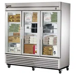
Fig. 1. Door channel openings (two-door units ONLY).
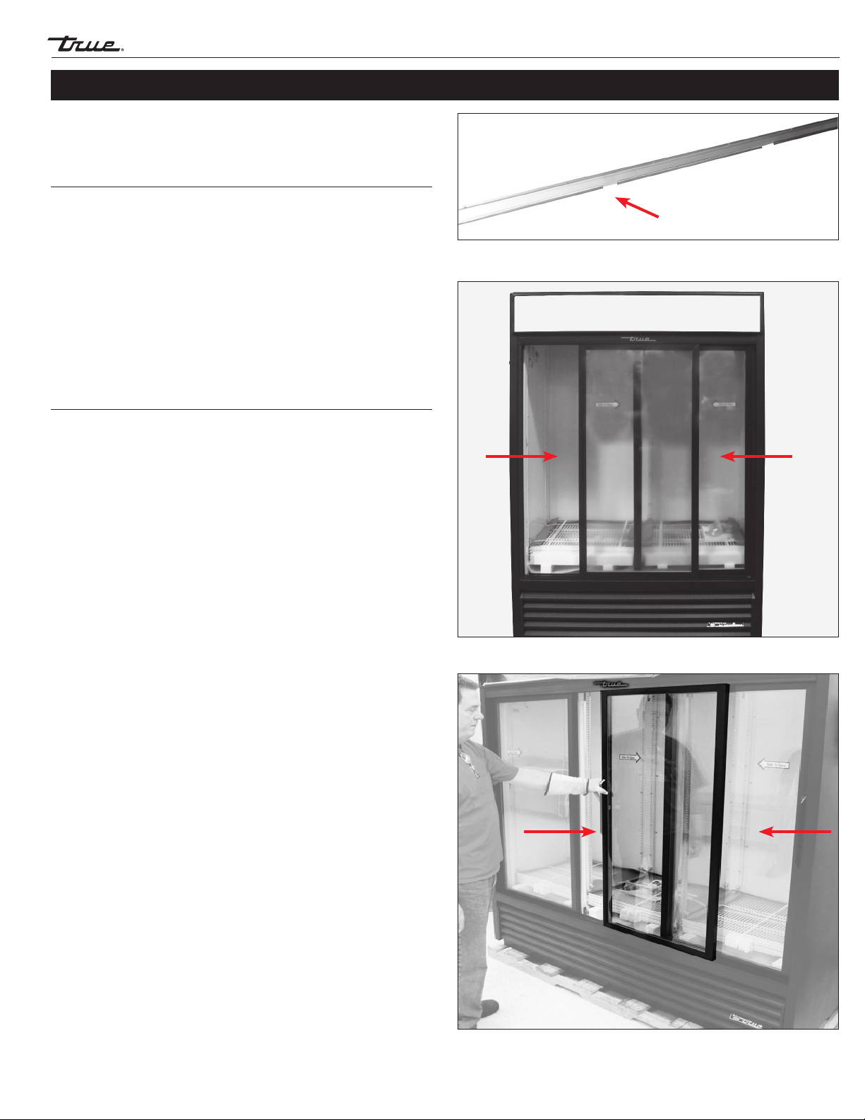
Fig. 2. Two-Door Units: Position the front door at the center of the cabinet.
Fig. 3. Three-Door Units: Center the middle door on the left edge of the right door.
CENTERED DOORCENTERED DOOR
CENTERED DOORCENTERED DOOR
Loading ...
Loading ...
Loading ...