
Loading ...
Loading ...
Loading ...
TRADITIONAL REACH-INS
TEC_TM_121 | REV. B | EN 07/14/2021 Page 5 of 22
truemfg.com
115
Volts Distance In Feet To Center of Load
AMPS 20 30 40 50 60 70 80 90 100 120 140 160
2 14 14 14 14 14 14 14 14 14 14 14 14
3 14 14 14 14 14 14 14 14 14 14 14 12
4 14 14 14 14 14 14 14 14 14 12 12 12
5 14 14 14 14 14 14 14 12 12 12 10 10
6 14 14 14 14 14 14 12 12 12 10 10 10
7 14 14 14 14 14 12 12 12 10 10 10 8
8 14 14 14 14 12 12 12 10 10 10 8 8
9 14 14 14 12 12 12 10 10 10 8 8 8
10 14 14 14 12 12 10 10 10 10 8 8 8
12 14 14 12 12 10 10 10 8 8 8 8 6
14 14 14 12 10 10 10 8 8 8 6 6 6
16 14 12 12 10 10 8 8 8 8 6 6 6
18 14 12 10 10 8 8 8 8 8 8 8 5
20 14 12 10 10 8 8 8 6 6 6 5 5
25 12 10 10 8 8 6 6 6 6 5 4 4
30 12 10 8 8 6 6 6 6 5 4 4 3
35 10 10 8 6 6 6 5 5 4 4 3 2
40 10 8 8 6 6 5 5 4 4 3 2 2
45 10 8 6 6 6 5 4 4 3 3 2 1
50 10 8 6 6 5 4 4 3 3 2 1 1
230
Volts Distance In Feet To Center of Load
AMPS 20 30 40 50 60 70 80 90 100 120 140 160
5 14 14 14 14 14 14 14 14 14 14 14 14
6 14 14 14 14 14 14 14 14 14 14 14 12
7 14 14 14 14 14 14 14 14 14 14 12 12
8 14 14 14 14 14 14 14 14 14 12 12 12
9 14 14 14 14 14 14 14 14 12 12 12 10
10 14 14 14 14 14 14 14 12 12 12 10 10
12 14 14 14 14 14 14 12 12 12 10 10 10
14 14 14 14 14 14 12 12 12 10 10 10 8
16 14 14 14 14 12 12 12 10 10 10 8 8
18 14 14 14 12 12 12 10 10 10 8 8 8
20 14 14 14 12 10 10 10 10 10 8 8 8
25 14 14 12 12 10 10 10 10 8 8 6 6
30 14 12 12 10 10 10 8 8 8 6 6 6
35 14 12 10 10 10 8 8 8 8 6 6 5
40 14 12 10 10 8 8 8 6 6 6 5 5
50 12 10 10 8 6 6 6 6 6 5 4 4
60 12 10 8 6 6 6 6 6 5 4 4 3
70 10 10 8 6 6 6 5 5 4 4 2 2
80 10 8 8 6 6 5 5 4 4 3 2 2
90 10 8 6 6 5 5 4 4 3 3 1 1
100 10 8 6 6 5 4 4 3 3 2 1 1
Wire Gauge Chart
Installation (cont.)
Wiring Conversion
Receptacle Box
1. Turn off the circuit breaker
2. Disconnect the existing receptacle.
3. Cap the red wire.
4. Connect the black, white, and green wires to the 3-prong
NEMA 5-20P plug per instructions on the receptacle.
Breaker Panel
1. Disconnect and remove the existing double-pole breaker.
2. Install a single-pole breaker
3. Connect the black wire to the replacement breaker
4. Cap the red wire
5. Turn on the circuit breaker.
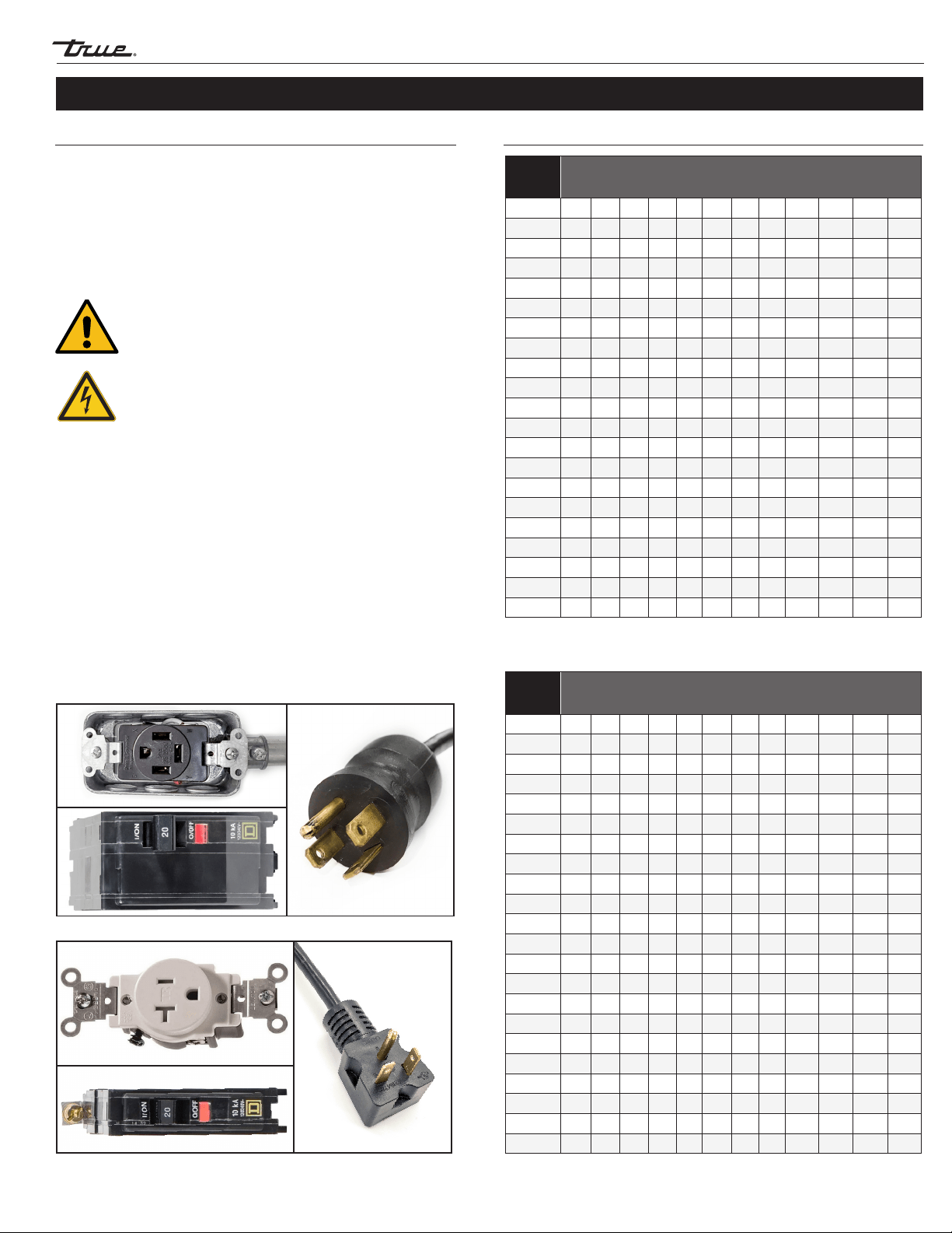
Wiring Instruction Advisement (115V only)
Follow the instructions below to convert your TRUE unit from
a 4-wire circuit and a 4-prong NEMA 14-20P (see components
in fig. 1) to a 3-wire circuit and a 3-prong NEMA 5-20P (see
components in fig. 2).
NOTE: Power cord conversion kit available for purchase
to match current installation location’s wiring
configuration
CAUTION – It is the customer’s responsibility to make
sure receptacle wiring meets all local electrical codes.
TRUE recommends hiring a licensed qualified
electrician to make this change.
Fig. 1. 4-wire configuration and 4-prong NEMA 14-20P/20R.
Fig. 2. 3-wire configuration and 3-prong NEMA 5-20P/20R.
CAUTION – Electrical shock or burn hazard. Unplug the
unit or turn off the power supply before proceeding.
Loading ...
Loading ...
Loading ...