Loading ...
Loading ...
Loading ...
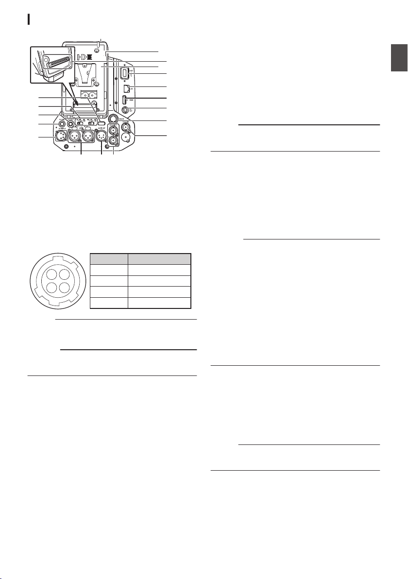
Rear Terminal
.
M
L
N
P
J
I
K
D
E
B
A
C
O
Q
GHF
R
A
Back Tally Lamp (Rear)
(A P46 [Tally Lamp] )
(A P222 [Blinking of the Tally Lamp] )
B
[AUDIO INPUT1/2] Switch
(A P69 [Audio Recording] )
C
[DC OUT] Terminal (Rear)
Supplies power to an externally-connected
wireless receiver.
.
14
23
1
2
3
4
UNREG GND
NC
NC
UNREG +12V
Signal Name
Pin Number
Memo :
0
The pin configurations for C and K are the
same.
Caution :
0
Do not connect it to any device other than an
external wireless receiver.
D
[PHONE] Terminal (Φ3.5 mm)
(A P181 [Connecting the Headphone] )
E
[DC INPUT] Terminal
Input terminal for DC 12 V power supply. For
connecting a separately sold AC adapter.
(A P33 [Using AC Power (DC IN Power)] )
F
[AUDIO INPUT1/2] Terminal (XLR 3-pin)
G
[AUDIO OUT] Terminal (XLR 5-pin)
Outputs audio signals of AUDIO CH1/CH2 or
CH3/CH4.
Audio signals are output according to the
setting in [A/V Set] B [Audio Set] B [AUDIO
OUT Ch.].
H
[HD/SD SDI OUT1/2] Terminal
(A P179 [Connecting External Monitor] )
I
[HD/SD SDI IN] Terminal
(A P182 [Inputting External Synchronizing
Signals (Genlock)] )
J
[REMOTE] Terminal
(A P180 [Connecting a Remote Control Unit] )
K
[DC OUT] (LAN) Terminal
Supplies power to devices such as a mobile
router that is connected to the [LAN] terminal.
Memo :
0
The pin configurations for C and K are the
same.
L
[HDMI] Output Terminal
(A P179 [Connecting External Monitor] )
M
[LAN] Terminal
For connecting the LAN cable.
N
[HOST] USB Host Terminal
For connecting a USB adapter according to the
intended purpose when you are connecting the
unit to a network.
Caution :
0
When [System] B [Record Set] B [Record
Format] B [System] is configured to “High-
Speed”2, network cannot be used via
wireless LAN u v or the [HOST] terminal
(USB). Configure as follows in this case.
0
Set
[Network] B [Connection Setup] B [USB/
Int. WLAN] to “Off”. u v
0
Unplug the USB network adapter
Note that camera operation will come to an
emergency
stop and the power will turn off if the
above steps are not performed.
File data may be damaged if this happens while
recording is in progress.
O
Battery Loading Folder
The shape varies across the U and E models.
* The E model is used in the illustration here.
(A P34 [Using a Battery Pack] )
P
Expansion Unit Terminal
Terminal for connecting a FS-790 (sold
separately) or other units.
Memo :
0
Remove the battery loading folder when using
this terminal.
Q
D-TAP terminal (IDX)v x
R
D-TAP terminal (Anton/Bauer)u w
Names of Parts
27
Introduction
Loading ...
Loading ...
Loading ...