
.
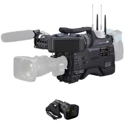
HD MEMORY CARD CAMERA RECORDER
GY-HC900CHU/GY-HC900CHE
GY-HC900STU/GY-HC900RCHE
INSTRUCTIONS
.
.
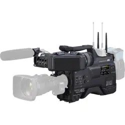
In this illustration, the supplied viewfinder is attached to the GY-HC900CHU/GY-HC900CHE.
Wireless LAN antenna and viewfinder are not included in GY-HC900STU and GY-HC900RCHE.
The specifications and appearance of this product are subject to changes for further improvement
without prior notice.
Please check the latest version of the INSTRUCTIONS from the following Mobile User Guide. You can
also download the PDF from the Mobile User Guide.
Mobile User Guide
When you are outside, you can refer to the instructions from your Android phone or iPhone.
http://manual3.jvckenwood.com/pro/mobile/global/
You can view the Mobile User Guide using the browser on your Android phone or iPhone.
Thank you for purchasing this product.
Before operating this unit, please read the
instructions carefully to ensure the best
possible performance.
In this manual, each model number is
described without the last letter (U/E) which
means the shipping destination.
(U: for USA and Canada, E: for Europe)
Only “U” models (GY-HC900CHU/
GY-HC900STU) have been evaluated by UL.
Please read the following before getting started:
For Customer Use:
Model No.
Serial No.
Enter below the Serial No. which is located
on the body.
Retain this information for future reference.
GY-HC900CHU/GY-HC900STU
IM 2.04
B5A-2755-00

2
.
1.
Read these instructions.
2.
Keep these instructions.
Important Safety Instructions
4.
5.
6.
7.
8.
These are general Important Safety Instructions and certain items may not
apply to all appliances.
3.
FOR USA
9.
10.
11.
12.
13.
For USA-California Only
This product contains a CR Coin Cell Lithium Battery which contains Perchlorate
Material – special handling may apply.
See www.dtsc.ca.gov/hazardouswaste/perchlorate
Heed all warnings.
Follow all instructions.
Do not use this apparatus near water.
Clean only with dry cloth.
Do not block any ventilation openings. Install in accordance with the manufacturer’s
instructions.
Do not install near any heat sources such as radiators, heat registers, stoves, or
other apparatus (including amplifiers) that produce heat.
Protect the power cord from being walked on or pinched particularly at plugs,
convenience receptacles, and the point where they exit from the apparatus.
Only use attachments/accessories specified by the manufacturer.
Use only with the cart, stand, tripod, bracket, or table
specified by the manufacturer, or sold with the apparatus.
When a cart is used, use caution when moving the
cart/apparatus combination to avoid injury from tip-over.
Unplug this apparatus during lightning storms or when
unused for long periods of time.
Refer all servicing to qualified service personnel.
Servicing is required when the apparatus has been damaged in any way, such as
power-supply cord or plug is damaged, liquid has been spilled or objects have fallen
into the apparatus, the apparatus has been exposed to rain or moisture, does not
operate normally, or has been dropped.
Important Safety Instructions
3
Introduction
.
4.
5.
6.
7.
8.
9.
10.
11.
12.
13.
Pour Californie des États-Unis seulement
Cet appareil contient une pile-bouton CR au lithium qui contient du perchlorate – une
manipulation spéciale peut être requise.
Voir www.dtsc.ca.gov/hazardouswaste/perchlorate
Respecter toutes les instructions.
Ne pas utiliser cet appareil à proximité de l’eau.
Ne nettoyer qu’avec un chiffon sec.
Ne pas boucher les ouvertures de ventilation.
Installer selon les instructions du fabricant.
Ne pas installer à proximité de sources de chaleur telles que des radiateurs,
des accumulateurs de chaleur, des poêles, ou d’autres appareils
(comprenant les amplificateurs) qui produisent de la chaleur.
Protéger le cordon d’alimentation pour éviter qu’il ne soit piétiné ou ne se coince, tout
particulièrement au niveau de la fiche, de la prise de courant et du point où il sort de l’appareil.
Utiliser uniquement des équipements/accessoires spécifiés par le fabricant.
N’utiliser qu’avec le chariot, le stand, le trépied, le support ou
la table spécifié par le fabricant, ou vendu avec l’appareil.
Lorsqu’un chariot est utilisé, faire attention pour déplacer
la combinaison chariot/appareil pour éviter des blessures
causées par un basculement.
Débrancher cet appareil pendant un orage ou quand il
n’est pas utilisé pendant une longue durée.
L’entretien ou la réparation de l’appareil doit être effectué par du personnel qualifié uniquement.
Un dépannage est nécessaire lorsque l’appareil a été endommagé d’une façon ou d’une autre,
telle que lorsque le cordon d’alimentation ou la fiche est endommagé, si du liquide a été renversé
ou si des objets sont tombés à l’intérieur de l’appareil, si l’appareil a été exposé à la pluie ou
à l’humidité, ne fonctionne pas normalement ou a fait une chute.
1.
Lire ces instructions.
2.
Conserver ces instructions.
CONSIGNES DE SÉCURITÉ IMPORTANTES
Ces informations sont des CONSIGNES DE SÉCURITÉ IMPORTANTES et
certains points peuvent ne pas s’appliquer à tous les appareils.
3.
POUR LES ÉTATS-UNIS
Tenir compte de tous les avertissements.
4
Important Safety Instructions
Introduction
Safety Precautions
.
CAUTION
FOR USA AND CANADA
CAUTION:
TO REDUCE THE RISK OF
ELECTRIC SHOCK.
DO NOT REMOVE COVER (OR
BACK).
NO USER-SERVICEABLE PARTS
INSIDE. REFER SERVICING TO
QUALIFIED SERVICE
PERSONNEL.
The lightning flash with
arrowhead symbol, within
an equilateral triangle is
intended to alert the user to
the presence of uninsulated
“dangerous voltage” within
the product’s enclosure that
may be of sufficient
magnitude to constitute a
risk of electric shock to
persons.
The exclamation point within
an equilateral triangle is
intended to alert the user to
the presence of important
operating and maintenance
(servicing) instructions in
the literature accompanying
the appliance.
RISK OF ELECTRIC
SHOCK
DO NOT OPEN
.
POUR CANADA
RISQUE
D’ELECTROCUTION
NE PAS OUVRIR
ATTENTION:
POUR EVITER TOUT RISQUE
D’ELECTROCUTION NE PAS
OUVRIR LE BOITER. AUCUNE
PIECE INTERIEURE N’EST A
REGLER PAR L’UTILISATEUR. SE
REFERER A UN AGENT QUALIFIE
EN CAS DE PROBLEME.
ATTENTION
Le symbole de l’éclair à
l’intérieur d’un triangle
équilatéral est destiné à
alerter l’utilisateur sur la
présence d’une “tension
dangereuse” non isolée dans
le boîtier du produit. Cette
tension est suffisante pour
provoquer l’électrocution de
personnes.
Le point d’exclamation à
l’intérieur d’un triangle
équilatéral est destiné à
alerter l’utilisateur sur la
présence d’opérations
d’entretien importantes au
sujet desquelles des
renseignements se trouvent
dans le manuel
d’instructions.
Ces symboles ne sont
utilisés qu’aux Etats-Unis.
Safety Precautions
5
Introduction

.
Supplier's Declaration of Conformity
Model Number: GY-HC900CHU
GY-HC900STU
Trade Name: JVC
Responsible JVCKENWOOD USA
party: Corporation
Address: 500 Valley Road,
Suite 203 Wayne,
NJ 07470
Telephone 973-317-5000
Number:
This device complies with Part 15 of
FCC Rules. Operation is subject to the
following two conditions: (1) This
device may not cause harmful
interference, and (2) this device must
accept any interference received,
including interference that may cause
undesired operation.
.
Changes or modifications not
approved by JVC could void the
user’s authority to operate the
equipment. This equipment has been
tested and found to comply with the
limits for a Class A digital device,
pursuant to Part 15 of the FCC Rules.
These limits are designed to provide
reasonable protection against harmful
interference when the equipment is
operated in a commercial
environment.
This equipment generates, uses, and
can radiate radio frequency energy
and, if not installed and used in
accordance with the instructions, may
cause harmful interference to radio
communications. Operation of this
equipment in a residential area is
likely to cause harmful interference in
which case the user will be required
to correct the interference at his own
expense.
.
Numéro de
modèle :
Nom de marque :
Personne
responsable :
Adresse :
Numéro de
téléphone :
Déclaration de conformité du fournisseur
GY-HC900CHU
GY-HC900STU
JVC
JVCKENWOOD USA
Corporation
500 Valley Road,
Suite 203 Wayne,
NJ 07470
973-317-5000
Cet ensemble se conforme à la partie 15 des
règles de la FCC (Federal Communications
Commission). Le fonctionnement est sujet aux
deux conditions suivantes : (1) Cet appareil ne
peut pas causer d’interférences nuisibles, et
(2) cet appareil doit accepter toute interférence
reçue, comprenant des interférences qui
peuvent causer un mauvais fonctionnement.
.
Des changements ou modifications
non approuvés par JVC peuvent
annuler le droit de l’utilisateur de faire
fonctionner l’appareil. Cet appareil a
été testé et il a été reconnu qu’il se
conforme aux limites concernant
l’appareillage informatique de classe
A correspondant à la partie 15 des
règles de la FCC. Ces limites sont
conçues pour fournir une protection
raisonnable contre les interférences
dangereuses lorsque l’équipement est
utilisé dans un environnement
commercial.
Cet appareil génère, utilise et peut
émettre de l’énergie des fréquences
radio et, s’il n’est pas installé et utilisé
selon les instructions du fabricant,
peut causer des interférences
nuisibles en communications radio.
L’utilisation de cet équipement dans
une zone résidentielle est susceptible
de causer des interférences néfastes,
auquel cas l’utilisateur devra prendre
des mesures à ses propres frais.
6
Safety Precautions
Introduction

.
CAUTION:
The mains plug shall remain readily
operable.
Remove the mains plug immediately if
the camera functions abnormally.
.
WARNING:
The battery pack, the camera with
battery installed, and the remote control
with battery installed should not be
exposed to excessive heat such as direct
sunlight, fire or the like.
.
WARNING: TO PREVENT FIRE OR
SHOCK HAZARD, DO NOT
EXPOSE THIS UNIT TO RAIN OR
MOISTURE.
.
NOTES:
The rating plate and safety caution are
on the bottom and/or the back of the
main unit.
The serial number plate is on the
bottom of the unit.
.
Caution on Replaceable lithium
battery
The battery used in this device may
present a fire or chemical burn hazard if
mistreated.
Do not recharge, disassemble, heat
above 100°C (212°F) or incinerate.
Replace battery with Panasonic, Sanyo,
Sony or Maxell CR2025.
Danger of explosion or risk of fire if the
battery is incorrectly replaced.
Dispose of used battery promptly.
Keep away from children.
Do not disassemble and do not dispose
of in fire.
.
Attention:
La prise secteur doit être opérationnelle.
Débranchez immédiatement la fiche
secteur si le caméscope ne fonctionne
pas normalement.
.
Avertissement:
Évitez d’exposer la batterie, le
caméscope avec la batterie insérée ou la
télécommande avec la batterie insérée à
une chaleur excessive, telle que celle
des rayons directs du soleil, d’un feu ou
de tout autre source de chaleur.
.
AVERTISSEMENT : POUR EVITER
LES RISQUES D’INCENDIE OU
D’ELECTROCUTION, NE PAS
EXPOSER L’APPAREIL A LA
PLUIE NI A L’HUMIDITE.
.
REMARQUES :
La plaque d’identification et
l’avertissement de sécurité se trouvent
sous l’appareil et/ou au dos.
La plaque du numéro de série est
située sur la partie inférieure de
l’appareil.
.
Avertissement sur la pile au
lithium remplaçable
La pile utilisée dans cet appareil peut
présenter des risques d’incendie ou de
brûlure chimique si elle est mal traitée.
Ne pas recharger, démonter, chauffer à
plus de 100°C (212°F) ni mettre au feu.
Remplacez la pile avec Panasonic,
Sanyo, Sony ou Maxell CR2025.
Danger d’explosion ou risque d’incendie
si la pile n’est pas changée correctement.
Jeter immédiatement les piles usées.
Placer hors de la portée des enfants.
Ne pas démonter ni jeter au feu.
Safety Precautions
7
Introduction

.
When the equipment is installed in a
cabinet or on a shelf, make sure that it
has sufficient space on all sides to allow
for ventilation (10 cm (3-15/16
") or more
on both sides, on top and at the rear).
Do not block the ventilation holes.
(If the ventilation holes are blocked by a
newspaper, or cloth etc. the heat may not
be able to get out.)
No naked flame sources, such as lighted
candles, should be placed on the
apparatus.
When discarding batteries,
environmental problems must be
considered and the local rules or laws
governing the disposal of these batteries
must be followed strictly.
.
The apparatus shall not be exposed to
dripping or splashing and that no objects
filled with liquids, such as vases, shall be
placed on the apparatus.
.
Do not point the lens directly into the
sun. This can cause eye injuries, as well
as lead to the malfunctioning of internal
circuitry. There is also a risk of fire or
electric shock.
CAUTION!
The following notes concern possible
physical damage to this unit and to the
user.
Carrying or holding this unit by the LCD
monitor can result in dropping the unit,
or in a malfunction.
Do not use a tripod on unsteady or
unlevel surfaces. It could tip over,
causing serious damage to the unit.
CAUTION!
Connecting cables (Audio/Video, etc.) to
this unit and leaving it on top of the TV is
not recommended, as tripping on the
cables will cause the unit to fall, resulting
in damage.
.
Si le matériel est installé dans un coffret
ou sur une étagère, s’assurer qu’il y a un
espace suffisant sur tous les côtés pour
permettre la ventilation (10 cm (3-15/16")
ou plus sur les deux côtés, au dessus et
à l’arrière).
Ne pas boucher les orifices de
ventilation.
(Si les orifices de ventilation sont
bouchés par un journal, un tissu, etc., la
chaleur peut ne pas s’éliminer.)
Aucune source à flamme nue, telle que
des bougies allumées, ne doit être
placée sur l’appareil.
En jetant des batteries aux ordures, les
problèmes d’environnement doivent être
pris en considération et les
réglementations locales ou la législation
concernant le rebut de ces batteries
doivent être strictement respectées.
.
L’appareil ne doit pas être exposé à de
l’eau ou à des éclaboussures et les
objets remplis de liquide, tels que des
vases, ne doivent pas être placés sur
l’appareil.
.
Ne dirigez pas l’objectif directement vers
le soleil. Vous pourriez vous abîmer la
vue et l’appareil pourrait être
endommagé. Il y a aussi risque
d’incendie ou d’électrocution.
Attention!
Les remarques suivantes sont destinées
à protéger l’utilisateur et le caméscope
contre des dommages éventuels.
Ne pas transporter ou saisir le
caméscope par l’écran LCD, car il
pourrait tomber ou s’endommager.
Ne pas utiliser de trépied
photographique sur des surfaces
irrégulières et inclinées. Il pourrait
tomber et le caméscope pourrait être
sérieusement endommagé.
Attention!
Avec des câbles (Audio/Vidéo, etc.)
raccordés, il est recommandé de ne pas
laisser le caméscope sur le dessus du
téléviseur, car tirer sur les câbles
pourrait faire tomber le caméscope,
causant des dommages.
8
Safety Precautions
Introduction
.
IMPORTANT (for owners in the U.K.)
Connection to the mains supply in
the United Kingdom.
DO NOT cut off the mains plug from
this equipment.
If the plug fitted is not suitable for the
power points in your home or the cable is
too short to reach a power point, then
obtain an appropriate safety approved
extension lead or contact the local
dealers in your area.
BE SURE to replace the fuse only with
an identical approved type, as originally
fitted, and to replace the fuse cover.
If nonetheless the mains plug is cut off
be sure to remove the fuse and dispose
of the plug immediately, to avoid possible
shock hazard by inadvertent connection
to the mains supply.
If this product is not supplied fitted with a
mains plug then follow the instructions
given below:
DO NOT make any connection to the
Larger Terminal coded E or Green.
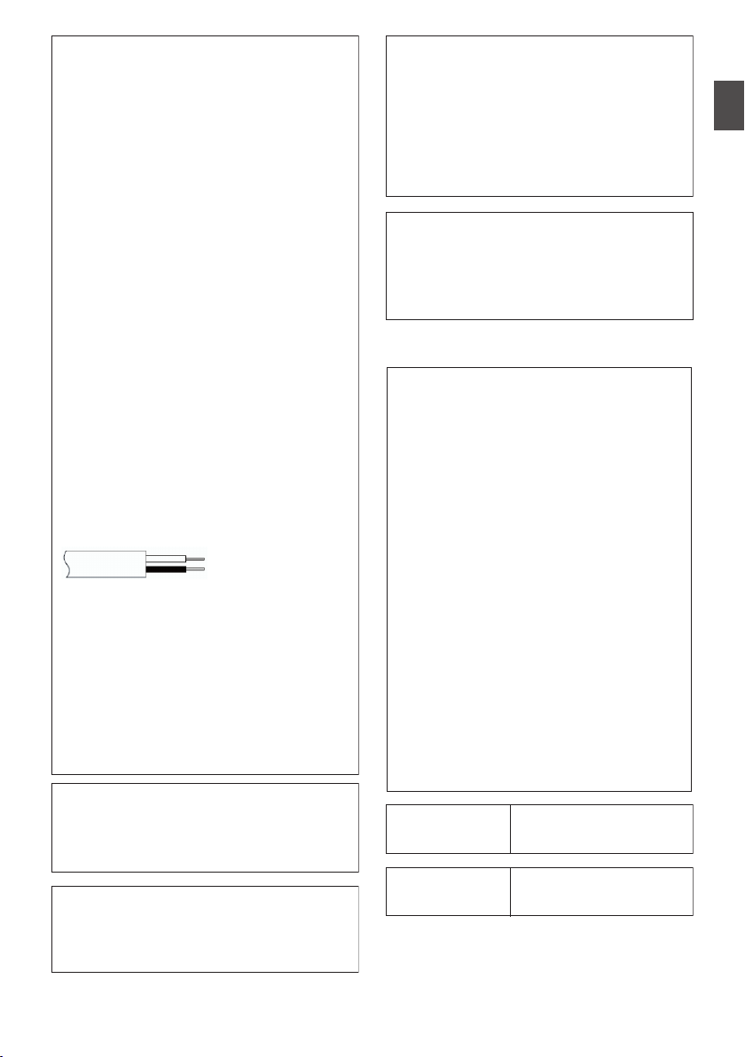
The wires in the mains lead are coloured
in accordance with the following code:
If these colours do not correspond with
the terminal identifications of your plug,
connect as follows:
Blue wire to terminal coded N (Neutral)
or coloured black.
Brown wire to terminal coded L (Live) or
coloured Red.
If in doubt
— consult a competent
electrician.
CAUTIONS:
To prevent shock, do not open the cabinet.
No user serviceable parts inside.
Refer servicing to qualified personnel.
Blue to N
(Neutral) or Black
Brown to L (Live)
or Red
.
WARNING
Operation of this equipment in a
residential environment could cause
radio interference.
.
CAUTION:
Where there are strong electromagnetic
waves or magnetism, for example near a
radio or TV transmitter, transformer,
motor, etc., the picture and the sound
may be disturbed. In such case, please
keep the apparatus away from the
sources of the disturbance.
.
The plastics packaging bags may cause
suffocation when they are covered over the
head. Tear them open, and keep them away
from the reach of infants and children by
ensuring that they are disposed of properly.
v
.
Wireless LAN
This device is a 2.4 GHz wideband
transmission system (transceiver),
intended for use in all EU member
states and EFTA countries, except in
France and Italy where restrictive use
applies.
In Italy the end-user should apply for a
license at the national spectrum
authorities in order to obtain
authorization to use the device for
setting up outdoor radio links and/or for
supplying public access to
telecommunications and/or network
services.
This device may not be used for setting
up outdoor radio links in France and in
some areas the RF output power may
be limited to 10 mW EIRP in the
frequency range of 2454 - 2483.5 MHz.
For detailed information the end-user
should contact the national spectrum
authority in France.
.
Frequency Range
Output Power
2.4GHz Band : 1 - 13ch
11 b/g/n : 14 dBm
(max)
.
Frequency Range
Output Power
5GHz Band : W52/W53/W56
11 n/a/ac : 11 dBm (max)
Safety Precautions
9
Introduction

v x
.
The European representative of
JVC KENWOOD Corporation is:
Die europäische Vertretung für die
JVC KENWOOD Corporation ist:
JVCKENWOOD Deutschland GmbH
Konrad-Adenauer-Allee 1-11
61118 Bad Vilbel
GERMANY
x
.
Dear customer,
this apparatus is in compliance with the
valid European Directive and the
relevant standards regarding
electromagnetic compatibility.
Sehr geehrter Kunde, sehr geehrte
Kundin,
dieses Gerät stimmt mit der gültigen
europäischen Richtlinie und den
relevanten Normen bezüglich
elektromagnetischer Verträglichkeit
überein.
v
.
Hereby, JVC KENWOOD Corporation
declares that the radio equipment type
GY-HC900CHE is in compliance with
Directive 2014/53/EU.
The full text of the EU declaration of
conformity is available at the following
internet address:
Hiermit erklärt die , JVC KENWOOD
Corporation, dass der Funkanlagentyp
GY-HC900CHE der Richtlinie
2014/53/EU entspricht.
Der vollständige Text der
EU-Konformitätserklärung ist unter der
folgenden Internetadresse verfügbar:
http://www3.jvckenwood.com/ecdoc/
.
Para Brasil
Informação sobre eliminação de
baterias
Este produto não deverá ser eliminado
como lixo doméstico em geral.
Devolva a bateria velha ao comerciante
ou para a rede autorizada, para que seja
devolvida ao fabricante ou importador.
A reciclagem e eliminação de lixo em
uma maneira adequada, ajudarão para
preservar recursos, prevenindo, ao
mesmo tempo, contra efeitos prejudiciais
sobre a nossa saúde e o meio ambiente.
o
10
Safety Precautions
Introduction

Contents
Introduction
Safety Precautions
............................................ 5
Contents .......................................................... 11
Main Features ................................................. 14
Precautions for Proper Use ............................. 16
Operation Modes ............................................. 20
Names of Parts ................................................ 22
Side Control Panel ....................................... 24
Side Terminal Section .................................. 26
Rear Terminal .............................................. 27
Electronic Viewfinder u v .................. 28
Basic System Diagram .................................... 29
Preparations
Settings and Adjustments Before Use ............. 30
Attaching the Lens (Sold Separately) ........... 30
Attaching the Viewfinder (Supplied) u v
..................................................................... 30
Attaching the Microphone (Sold Separately)
..................................................................... 31
Attaching the Video Light (Sold Separately) 31
Attaching the Wireless LAN Antennas
(Supplied) u v ................................... 32
Attaching the Tripod (Sold Separately) ........ 32
Adjusting the Position of the Shoulder Pad .. 32
Power Supply .................................................. 33
Using AC Power (DC IN Power) ................... 33
Using a Battery Pack .................................... 34
Battery Warning Settings ............................. 35
Power Status Display ...................................... 36
Turning On/Off the Power ................................ 37
Initial Settings .................................................. 38
Displays on the LCD Monitor and Viewfinder .. 40
Display Screen ............................................. 40
Status Screen .............................................. 41
Remote Edit Mode Screen ........................... 41
Warning Display ........................................... 41
Adjusting the LCD Monitor and Viewfinder ...... 42
Adjusting the LCD Monitor ........................... 42
Adjusting the Viewfinder .............................. 42
Adjusting the Back Focus ................................ 44
Assignment of Functions to User Buttons ........ 45
Tally Lamp ....................................................... 46
SD Card ........................................................... 47
Usable Cards ...............................................
47
Estimated Recordable Time of SD Cards .... 47
Inserting an SD Card .................................... 48
Removing the SD Card ................................ 49
Switching the SD cards ................................ 49
Formatting (Initializing) SD Cards ................ 50
Restoring the SD Card ................................. 51
Clips Recorded to SD Cards ........................ 52
Operation Lock Feature ................................... 53
Shooting
Basic Shooting Procedures ............................. 54
Selecting System Definition, File Format and Video
Format ............................................................. 55
Zoom Operation .............................................. 57
Focus Operation .............................................. 58
Adjusting the Brightness .................................. 59
Adjusting the Iris .............................................. 60
Setting the Gain ............................................... 61
Setting the Electronic Shutter .......................... 62
Adjusting the White Balance ............................ 63
Adjusting the Camera Image ........................... 69
Audio Recording .............................................. 69
Audio Output during Recording ....................... 73
Time Code and User’s Bit ................................ 73
Setting Time Code Generator .......................... 74
Setting the User’s Bit ....................................... 77
Synchronizing the Time Code with an External
Time Code Generator ...................................... 78
Setting Zebra Pattern ...................................... 80
Setting Spot Meter ........................................... 81
Acquiring Positioning Information by GPS v
u ................................................................. 83
Viewing Recorded Videos Immediately (Clip
Review) ........................................................... 84
Displaying the Video Signal Monitor ................ 85
Recording Simultaneously at Two Different
Definitions 2 ............................................ 86
Series Rec ....................................................... 86
Dual Rec .......................................................... 86
Backup Rec 0 ......................................... 88
Special Recording 0 ................................ 90
Pre Rec 0 ............................................ 90
Clip Continuous Rec 0 ......................... 91
Frame Rec 1 ........................................ 92
Interval Rec 1 ...................................... 93
Splitting the Clips Freely (Clip Cutter Trig) 0
......................................................................... 94
Contents
11
Introduction

Playback
Playing Recorded Clips ................................... 95
Thumbnail Screen ........................................ 95
Actions ......................................................... 97
Playing back ................................................ 98
Deleting Clips ................................................ 100
Appending/Deleting OK Mark ........................ 101
Selecting and Performing Operations on Multiple
Clips .............................................................. 102
Selecting Multiple Clips Randomly ............. 102
Selecting Multiple Clips Consecutively ...... 103
Trimming Recorded Clips .............................. 104
Menu Display and Detailed Settings
Basic Operations in Menu Screen ................. 105
Display and Description of the Menu Screen
................................................................... 106
Text Input with Software Keyboard ............ 107
Menu Screen Hierarchical Chart ................... 108
Camera Function Menu ................................. 109
User Switch Set Item .................................. 111
Full Auto Item ............................................. 115
Camera Process Menu .................................. 116
Detail/Adjust Item ....................................... 121
White Balance Item .................................... 122
TC/UB Menu ................................................. 124
LCD/VF Menu ................................................ 125
Shooting Assist Item .................................. 126
Marker Settings Item .................................. 128
Display Type Item ...................................... 129
Display On/Off Item .................................... 130
A/V Set Menu ................................................ 131
Video Set Item ........................................... 131
Audio Set Item ........................................... 135
Network Menu ............................................... 139
Connection Setup Item .............................. 140
Live Streaming Item ................................... 141
Return over IP Item 0 ......................... 143
Web Item ................................................... 145
Metadata Server Item ................................ 145
Upload Item 0 .................................... 146
System Menu ................................................ 148
Record Set Item ......................................... 151
Adding/Editing Frequently Used Menu Items
(Favorites Menu) ........................................... 157
Adding Menu Items to Favorites Menu ...... 157
Editing Favorites Menu .............................. 158
Display/Status Screen
Display Screen in Camera Mode
................... 161
Display Screen in Media Mode ...................... 167
Status Screen ................................................ 170
Camera Features
Marker and Safety Zone Displays (Camera Mode
Only) .............................................................. 172
Color Bar Output ........................................... 172
Adjusting the Gamma .................................... 173
Adjusting Color Matrix ................................... 174
Configuring Setup Files ................................. 176
Saving Setup Files ..................................... 176
Loading a Setup File .................................. 177
Deleting Setup Files ................................... 178
Connecting External Devices
Connecting External Monitor ......................... 179
Connecting a Remote Control Unit ................ 180
Connecting the Headphone ........................... 181
Inputting External Synchronizing Signals
(Genlock) ....................................................... 182
Displaying Return Videos from an External
Device ........................................................... 184
Connecting to the Network
Functions of Network Connection .................. 185
Preparing Network Connection ...................... 186
Operating Environment .............................. 186
Camera Setup for Network Connection ..... 186
Connecting to Network via [LAN] Terminal
0 ........................................................ 186
Connecting to Network via [HOST] Terminal
(USB) 0 ............................................. 187
Connecting to Network via Built-in Wireless LAN
u v 0 ....................................... 188
Importing Metadata ....................................... 189
Preparing Metadata ................................... 189
Configuring the Server for Downloading .... 189
Importing Metadata .................................... 190
Uploading a Recorded Video Clip ................. 191
Configuring the FTP Server for Uploading . 191
Uploading Clips Automatically (Auto
FTP)0 ................................................ 191
Uploading Clips Manually (Manual FTP) .... 192
FTP Resume Feature .................................... 194
12
Contents
Introduction

Connecting from a Web Browser ................... 195
Editing Metadata ...........................................
195
Planning Metadata ..................................... 195
Clip Metadata ............................................ 196
Uploading a Recording Clip via a Web Browser
....................................................................... 199
View Remote Control and Camera Control
Functions ....................................................... 202
Changing the Settings via a Web Browser .... 204
Changing View Remote Function Settings . 205
Changing Connection Setup ...................... 205
Changing Metadata Server Settings .......... 206
Changing Clip Server Settings ................... 206
Changing Streaming Settings .................... 206
Managing the Network Connection Settings File
....................................................................... 207
Saving the Connection Settings File .......... 207
Reading the Connection Settings File ........ 208
Deleting Connection Settings .................... 209
Performing Live Streaming ............................ 210
Setting Distribution ..................................... 212
Starting Distribution ................................... 214
Setting the FEC Matrix 0 ................... 215
Return Video/Audio from the Network (Return over
IP)0 ....................................................... 216
IFB (Return Audio)0 .............................. 217
Others
Error Messages and Actions ......................... 218
List of FTP Transfer Errors ......................... 219
List of Live Streaming Error Displays ......... 221
Blinking of the Tally Lamp .......................... 222
Warning Tone ............................................ 222
Troubleshooting ............................................ 223
Specifications ................................................ 226
Appendix ....................................................... 231
Index ............................................................. 232
Software License Agreement ........................ 234
Important Notice concerning the Software ..... 235
.
Contents
13
Introduction

Main Features
A variety of wired and wireless
interfaces to support various network
connections
In addition to the USB host terminal for wireless
LAN and LTE USB adapter connections, this
camera recorder is equipped with a variety of
interfaces such as wired LAN terminal and built-in
wireless LAN with 2.4GHz/5GHz MIMO dual band
antennas u v to support various network
connections.
Three full HD 2/3-inch CMOS image
sensors for high sensitivity of F12, low
noise high quality recording
This camera recorder is equipped with three 2/3-
inch 2.20M pixels full HD CMOS image sensors.
It delivers high sensitivity of F12, low noise high
quality recordings.
2/3-inch B4 lens mount system
equipped with B4 lens mount and 4-
position optical ND filter
This camera recorder comes with a 2/3-inch B4
lens mount system equipped with B4 lens mount
and 4-position optical ND filter.
A wide range of B4 mount lenses can be used.
Furthermore, when a B4 lens with chromatic
aberration compensation data is installed,
chromatic aberration can be corrected on the
camera recorder.
By switching the 4-position ND filter (CLEAR, 1/4,
1/16, 1/64), the amount of light can be adjusted
according to the brightness during shooting.
High
quality signal processing by 10-bit,
4:2:2 sampling
High quality signal processing that delivers rich
gradation expression and color reproduction of
video signals is possible by means of 10-bit, 4:2:2
sampling.
Various
usage-based recording formats
The recording codec supports two types of formats
that are compatible with the 4:2:2 10-bit formats
widely used by broadcasting stations, namely
MPEG-4 AVC/H.264 and MPEG-2. All file formats
are compatible with QuickTime (MOV).
Newly developed user multi-matrix for
16-axis color correction
In addition to the conventional 6-axis user linear
matrix adjustment, this camera recorder is
equipped with user multi-matrix that enables
accurate adjustment of hue and saturation in the
smaller 16-axis color region.
HDR and log gamma for high dynamic
range and high color gamut
This camera recorder is equipped with HLG
(Hybrid Log-Gamma) that conforms to ITU-BT.
2100 and our in-house J-Log1 Gamma with 800%
dynamic range to cope with HDR (High Dynamic
Range). Capable of recording in 10-bit for high
dynamic range and high color gamut.
Double SD card slots for series/dual
recordings
The most common SDHC/SDXC card recording
system is used for the memory card. This ensures
high reliability and operation at low running cost.
Various user friendly recording options are
available. These include series recording which
enables seamless long hour continuous
recordings over the slots and dual recording of the
same file to two slots.
3.26-inch OLED electronic viewfinder
and 3.5-inch LCD monitor (with focus
assist function)
This camera recorder supports focusing through
the 3.26-inch OLED electronic viewfinder and 3.5-
inch LCD monitor. Other assist functions are also
available, including magnified focus on a manually
selected point.
Time code input/output and genlock
terminals for shooting using multiple
cameras
This camera recorder supports the use of multiple
cameras as well as studio use.
Professional-style switch layout and
diverse video parameters
Switches for Gain and White Balance are available
on the side panel to enable quick switching
according to the shooting scene. Image quality
parameters such as gamma and color matrix are
also available in the menu for adjustment to the
preferred tones.
14
Main Features
Introduction

Built-in GPS u v
This camera recorder is built in with GPS function,
which enables the positional information obtained
from the GPS satellite during a shoot to be
recorded as metadata.
* Note that acquisition of the positional
information may fail depending on the weather
condition.
User buttons/switches assignable with
different functions for greater ease of
use
Menu items corresponding to each user button are
available to assign the buttons with different
functions.
“IPX2” standard equivalent waterproof
function for shooting in the rain
SDI pool feed for simultaneous
recording and streaming of videos
Symbols used
Caution : Describes precautions concerning the
operation of this product.
Memo : Describes reference information, such
as functions and usage restrictions of
this product.
A
: Indicates the reference page numbers
and reference items.
u
: Feature available on GY-HC900CHU
only.
v
: Feature available on GY-HC900CHE
only.
w
: Feature available on GY-HC900STU
only.
x
: Feature available on GY-HC900RCHE
only.
0
: Feature available with firmware version
V0200-xxxx
1
: Feature available with firmware version
V0201-xxxx
2
: Feature available with firmware version
V0210-xxxx
o
: Feature that will be supported after
future firmware upgrade.
Content of this manual
0
All rights reserved by JVC KENWOOD
Corporation. Unauthorized duplication or
reprinting of this manual, in whole or in part, is
strictly prohibited.
0
Illustrated designs, specifications and other
contents of this manual are subject to change for
improvement without prior notice.
0
SDXC and SDHC logos are trademarks of
SD-3C, LLC.
0
The terms HDMI and HDMI High-Definition
Multimedia Interface, and the HDMI Logo are
trademarks or registered trademarks of HDMI
Licensing Administrator, Inc. in the United States
and other countries.
0
QuickTime, Final Cut Pro, iPhone, iPad, iPod
touch, macOS and Safari are trademarks of
Apple Inc., registered in the U.S. and other
countries.
0
iOS is a trademark or registered trademark of
Cisco in the U.S. and other countries and is used
under license.
0
Android and Google Chrome are trademarks
and/or registered trademarks of Google LLC.
0
QR Code is a registered trademark of Denso
Wave Incorporated.
0
Microsoft, Windows, and Internet Explorer are
either registered trademarks or trademarks of
Microsoft Corporation in the United States
and/or other countries.
0
The company name of Fontworks, Fontworks,
and the name of the fonts are registered
trademarks of Fontworks Inc.
0
Zixi and the Zixi logo are trademarks of Zixi LLC.
0
UniSlot is a registered trademark of Ikegami
Tsushinki Co., Ltd.
0
Other product and company names included in
this instruction manual are trademarks and/or
registered trademarks of their respective
companies. Marks such as ™ and ® have been
omitted in this manual.
Main Features
15
Introduction

Precautions for Proper
Use
Storage and Usage Locations
o
Allowable ambient temperature and humidity
Be sure to use this unit within the allowable
temperature range of 0 °C to 40 °C (32 °F to
104°F) and a relative humidity of 30 % to 80 %.
Using this unit at a temperature or humidity
outside the allowable ranges could result not
only in malfunction but also serious impact on
the CMOS elements as small white spots may
be generated. Please exercise care during use.
o
Strong electromagnetic waves or magnetism
Noise may appear in the picture or audio and/or
the colors may be incorrect if this unit is used
near a radio or television transmitting antenna,
in places where strong magnetic fields are
generated by transformers, motors, etc., or near
devices emitting radio waves, such as
transceivers or cellular phones.
o
Use of wireless microphone near this unit
When a wireless microphone or wireless
microphone tuner is used near this unit during
recording, the tuner could pick up noise.
o
Avoid using or placing this unit in the following
places.
0
Places subject to extreme heat or cold
0
Places with excessive dirt or dust
0
Places with high humidity or moisture
0
Places subject to smoke or vapor such as near
a cooking stove
0
Places subject to strong vibrations or unstable
surfaces
0
In a parked car under direct sunlight or near a
heater for long hours
o
Do not place this unit at places that are subject
to radiation or X-rays, or where corrosive gases
occur.
o
Protect this unit from getting wet when shooting
on a beach. In addition, salt and sand may
adhere to the body. Be sure to clean the unit after
use.
o
Protect this unit against penetration of dust
when using it in a place subject to sandy dust.
Drip-proof
o
This camera recorder has a drip-proof structure
equivalent to IPX2 according to our testing
method. It is not completely waterproof. And the
drip-proof performance under all conditions is
not guaranteed.
0
IPX2 (protection rating against dripping water)
ensures that when a device is tilted at an angle
of 15 degrees to the front, back, right and left
with water dripping vertically on it at a rate of
3 mm/min for a total of 10 minutes at 2 minutes
30 seconds for each position, the device will
function properly when operated.
o
To ensure the drip-proof performance, close the
caps and covers fully.
o
Avoid heavy rain and heavy water splashes.
o
If this camera recorder gets wet and there are
water droplets, wipe off with a dry cloth
immediately. If the camera recorder is turned
upside down or tilted at 15 ° or more while it is
wet, water may enter the camera recorder and
cause malfunction.
o
If this camera recorder gets wet, water may
come out from the gaps. Do not carry it while it
is wet. Place it on a dry cloth for a while and let
it dry.
Carrying the Camera
o
Do not drop or hit this unit against a hard object
when transporting.
Power Saving
o
When this unit is not in use, be sure to set the
[POWER ON/OFF] switch to “OFF” in order to
reduce power consumption.
Maintenance
o
Turn off the power before performing any
maintenance.
o
Wipe the external cabinet of the unit with a soft
cloth. Do not wipe the body with benzene or
thinner. Doing so may cause the surface to melt
or turn cloudy. When it is extremely dirty, soak
the cloth in a solution of neutral detergent, wipe
the body with it, and then use a clean cloth to
remove the detergent.
16
Precautions for Proper Use
Introduction

Rechargeable Battery
o
The batteries recommended for use with this
camera recorder are as follows.
U model : Digital 150 (Anton/Bauer)
E model : DUO-150 (IDX)
o
Please make use of one of the recommended
batteries.
Heavy batteries may fall off if they are not used
correctly.
Regular Inspection (Maintenance)
o
Under normal environment, dust will
accumulate on the camera recorder when it is
used over a long period. Dust may enter the
camera recorder especially if it is used outdoors.
This may affect the image and sound quality of
the camera recorder. Check and replace the fan
after every 9000 hours (suggested guideline).
You can check the usage time of the fan in
[System] B [System Information] B [Fan Hour].
(A P150 [ Fan Hour ] )
If the fan is used for more than 9000 hours
without replacement, “Fan Maintenance
Required” will be displayed every time you turn
on the power.
LCD Monitor and Viewfinder
u v
o
The LCD monitor and viewfinder screen are
manufactured using high-precision technology.
Black or bright spots may appear on the LCD
monitor and viewfinder screen. This is not a
malfunction. These spots will not be recorded.
o
If you use this unit continuously for a long period
of time, the characters displayed in the
viewfinder may temporarily remain on the
screen. This phenomenon will not be recorded
to the recording media. They will not appear
after you turn the power off and then on again.
o
If you use this unit in a cold place, the images
may appear to lag on the screen, but this is not
a malfunction. Retained images are not
recorded on the SD card.
o
Do not press against the surface with force or
subject it to strong impact. Doing so may
damage or break the screens.
o
Noise may appear in the viewfinder when
switching between the live video and playback
images.
o
Due to the characteristic of the viewfinder
display device, colors may appear on the
images when you blink your eyes. It does not
affect the recorded images, SDI output, or HDMI
output.
Lens
o
This camera recorder is an interchangeable lens
camera. Please have the interchangeable lens
ready before use.
o
Read the “INSTRUCTIONS” of the
interchangeable lens to be attached to get a full
understanding before use.
o
Optical performance of lens
Due to the optical performance of the lens, color
divergence phenomena (magnification
chromatic aberration) may occur at the
periphery of the image. This is not a camera
malfunction.
o
Depending on the lens attached, there are
function limitations on the lens with this camera
recorder or the lens may not function properly.
o
The lens operation sound may be recorded.
o
Depending on the lens used, the approximate
distance to the subject may not be displayed.
o
There can be a large variation in the light
intensity during Auto Iris mode, Manual Iris
mode and zoom mode.
GPS
u v
o
The GPS (Global Positioning System) satellites
are managed by the Department of State of the
U.S., and its precision may be altered
intentionally.
o
Perform positioning at an unobstructed location
with a clear view that is not indoors or blocked
by trees.
o
The time needed for obtaining the position
information may be longer and variation may
also be larger depending on the surrounding
environment and time of day.
o
This camera recorder uses the WGS 84 World
Geodetic System.
o
Signal from GPS satellites may be interrupted by
communication signal from electronic devices
such as mobile phones.
o
Make use of it in accordance with the regulations
of the country, region or location of use.
Encryption in Network Connection
o
Wireless LAN connections make use of an
encryption function.
This encryption is designed for commercially-
sold equipment, and it cannot be altered.
Precautions for Proper Use
17
Introduction

SDHC/SDXC Cards
o
SDHC/SDXC card is referred to as “SD card” or
“recording media” in this manual.
o
This camera recorder saves the recorded
images and audio sound on the SD card (sold
separately) in the card slot.
o
If the SD card contains files recorded by devices
other than this camera recorder or files that are
saved from a PC, the recordable time may be
shorter or data may not be properly recorded. In
addition, the remaining space on the card may
not increase even when files are deleted using
a PC.
o
For details on the combinations of usable SD
card and format setting, refer to the following.
(A P47 [Format Setting and Usable SD Card
Combinations] )
* Using cards other than those from Panasonic,
TOSHIBA or SanDisk may result in recording
failure or data loss.
Handling of SD Cards
o
The status indicator lights up in red when data
on the SD card is being accessed.
Do not remove the SD card during data access
(such as recording, playback, or formatting). Do
not turn off the power or remove the battery and
AC adapter during access either.
o
Do not use or store the SD card in a place that
is subject to static electricity or electrical noise.
o
Do not place the SD card near locations that are
exposed to strong magnetic fields or radio
waves.
o
Inserting the SD card incorrectly may result in
damage of this unit or the SD card.
o
We are not liable for any accidental loss of data
stored on the SD card. Please back up any
important data.
o
Make use of the SD card within the prescribed
conditions of use.
Do not use it at the following locations.
Places that are subject to direct sunlight, high
humidity or corrosion, places near thermal
equipment, sandy or dusty places, or in a car
under the sun with the doors and windows
closed.
o
Do not bend or drop the SD card, or subject it to
strong impact or vibration.
o
Do not splash the SD card with water.
o
Do not dismantle or modify the SD card.
o
Do not touch the terminals with your hands or
with a metal object.
o
Do not allow dust, dirt, water, or foreign objects
to adhere to the terminals.
o
Do not remove the labels or stick other labels or
stickers on the SD cards.
o
Do not use pencils or ballpoint pens to write on
the SD cards. Always use oil-based pens.
o
If you format (initialize) the SD card, all data
recorded on the card, including video data and
setup files, will be deleted.
o
You are recommended to use cards that are
formatted (initialized) on this camera recorder.
0
The SD card may be damaged if the camera
recorder is not operated correctly. Formatting
(Initializing) the SD card may allow it to
operate correctly.
0
SD cards that have been formatted
(initialized) on other cameras, computers or
peripheral equipment may not operate
correctly. In this case, format (initialize) the SD
card on this camera recorder.
o
If you want to wipe out all information by
completely erasing the data, we recommend
either using commercially available software
that is specially designed for that purpose, or by
physically destroying the SD card with a
hammer, etc. When formatting or erasing data
using the camera recorder, only the file
administration information is changed. The data
is not completely erased from the SD card.
o
Some commercially available SD cards may be
harder to be removed from this unit. Remove
them by hooking onto the groove on the cards.
0
It will be easier to remove the cards after
several times.
0
Do not stick any stickers on the cards.
.
Groove
o
The SD card may pop out when it is being
removed. Be careful not to lose the card.
Copyright
o
Any recordings made on this camera recorder
that are played back for profit or public preview
may infringe on the rights of the owner of the
recordings.
Do not use the recordings for purpose other than
personal enjoyment without prior consent from
the owner. And even for personal enjoyment,
you may not be able to record without
permission from the owner.
18
Precautions for Proper Use
Introduction

License Notices
o
MPEG LA AVC
THIS PRODUCT IS LICENSED UNDER THE
AVC PATENT PORTFOLIO LICENSE FOR
THE PERSONAL USE OF A CONSUMER OR
OTHER USES IN WHICH IT DOES NOT
RECEIVE REMUNERATION TO
(i) ENCODE VIDEO IN COMPLIANCE WITH
THE AVC STANDARD (“AVC VIDEO”) AND/OR
(ii) DECODE AVC VIDEO THAT WAS
ENCODED BY A CONSUMER ENGAGED IN A
PERSONAL ACTIVITY AND/OR WAS
OBTAINED FROM A VIDEO PROVIDER
LICENSED TO PROVIDE AVC VIDEO.
NO LICENSE IS GRANTED OR SHALL BE
IMPLIED FOR ANY OTHER USE. ADDITIONAL
INFORMATION MAY BE OBTAINED FROM
MPEG LA, L.L.C. SEE
HTTP://WWW.MPEGLA.COM
o
MPEG LA MPEG-2 Patent
ANY USE OF THIS UNIT IN ANY MANNER
OTHER THAN PERSONAL USE THAT
COMPLIES WITH THE MPEG-2 STANDARD
FOR ENCODING VIDEO INFORMATION FOR
PACKAGED MEDIA IS EXPRESSLY
PROHIBITED WITHOUT A LICENSE UNDER
APPLICABLE PATENTS IN THE MPEG-2
PATENT PORTFOLIO, WHICH LICENSE IS
AVAILABLE FROM MPEG LA, LLC, 6312 S.
WHICH LICENSE IS AVAILABLE FROM MPEG
LA, LLC, 6312 S. Fiddlers Green circle, Suite
400E, Greenwood Village, Colorado 80111
U.S.A.
Others
o
Do not insert objects other than the memory card
into the card slot.
o
Do not block the vent on the unit.
Blocking of the vent causes internal heating and
may lead to burns and fires.
o
Do not turn off the [POWER ON/OFF] switch or
remove the power cable during recording or
playback.
o
The camera recorder may not show stable
pictures for a few seconds immediately after the
power is turned on, but this is not a malfunction.
o
When the video signal output terminals are not
in use, put on the covers to prevent damage to
the terminals.
o
Do not drop this unit or subject it to strong impact
or vibration as it is a precision equipment.
o
Noise may appear in the image when switching
modes.
o
If placed on its side, heat release efficiency will
deteriorate.
o
When the connectors that come with connector
covers are not in use, put on the covers to
prevent damage to the connectors.
o
This camera recorder makes use of fonts by
Fontworks Inc.
o
This camera recorder makes use of M+FONTS.
o
Use the built-in wireless LAN only in the country
and region where it was purchased.
And there are legal restrictions on the use and
outdoor use depending on the country and
region. Please be careful not to violate the law.
u v
Precautions for Proper Use
19
Introduction
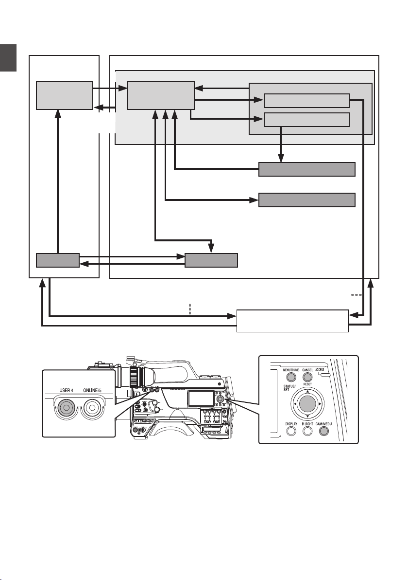
Operation Modes
This camera recorder has three operation modes - Camera mode, Media mode, and Remote Edit mode.
.
Trimming Playback
Normal Playback
Camera Input
(Actions)
Execute [Delete Clips]
File Deletion in Progress
Exit Trimming Operation
(Successful/Failed/Stopped)
Execute
[Trim This Clip]
Thumbnail Display
Playback
Camera Mode
Media Mode
Press and hold [CAM/MEDIA]
[CAM/MEDIA]
Button
[CANCEL/RESET]/[MENU/THUMB] Button
* Selecting a mode other than the Metadata Edit mode via the web
browser, or selecting [Exit] on the [Remote Edit Mode] screen
Upon access via a web browser and selecting [Change] on the
[Change to Remote Edit Mode?] screen on the camera or the web browser
*
Press and hold [CAM/MEDIA]
[CAM/MEDIA] Button
Exit FTP
Operation
(Successful)
[SET] Button (R)
Remote Edit Mode
FTP in Progress
FTP in Progress
[USER4]
Button
Trimming in Progress
Exit/Cancel File Delete Operation (Successful/Failed/Stopped)
Exit/Cancel FTP Operation (Successful/Failed/Stopped)
Execute [FTP Upload]
20
Operation Modes
Introduction

Operation Mode Description
Camera Mode
0
This
is the camera shooting mode. The camera recorder starts up in Camera mode
when the power is turned on.
0
Camera images are output to the viewfinder and LCD monitor. When a recordable
media is inserted, the camera recorder enters the recording standby mode. “STBY”
appears on the operation mode display area of the LCD monitor and viewfinder.
0
Press the [REC] trigger button to start recording.
0
When [Record
Set] B [Record Format] B [System] is set to “HD(SDI In)” or “SD(SDI
In)”2, and the device is connected to the [HD/SD SDI IN] terminal, the SDI
input video is displayed on the LCD monitor or viewfinder.
Memo :
0
Playback of recording media is not possible in the Camera mode. However, you
can check the most recently recorded video clip.
(A P84 [Viewing Recorded Videos Immediately (Clip Review)] )
Media Mode
0
This mode allows you to play back or delete clips recorded on the recording media.
0
When a playable recording media is inserted, the thumbnail or playback screen is
displayed on the viewfinder and LCD monitor.
0
Press and hold the [CAM/MEDIA] button to enter the Media mode when you are
not shooting in the Camera mode. Once the camera recorder is in Media mode,
thumbnails of the selected media slot are displayed.
Remote Edit
Mode
0
This mode enables the list display and editing of the recorded clip data through
access to the clip list display page via a web browser on a smartphone, tablet
terminal, or PC.
0
When you access via a web browser on a smartphone, tablet terminal, or PC, “It
is necessary to change the camera mode to "Remote Edit Mode". Change the
mode.” appears on the web browser. Also, “Change to Remote Edit Mode?” is
displayed on the display screen of the camera unit.
Selecting [Change] on the camera recorder and pressing the Set button switches
to the Remote Edit mode, and enables display of the clip list and editing of the clip
metadata.
(A P
196 [ Clip Metadata ] )
(A P199 [Uploading a Recording Clip via a Web Browser] )
Memo :
0
If you access via a web browser on devices such as a smartphone, tablet terminal,
or PC while recording is in progress, the message appears after recording stops.
0
If playback is in progress, the message appears once the files are closed
automatically, such as when playback stops.
Operation Modes
21
Introduction

Names of Parts
.
A
C
G K
B
D
E F H I J
A
Speaker
(A P98 [Audio Output during Playback] )
B
Viewfinder Left-Right Position Lock Ring
For loosening the ring and adjusting the position
of the viewfinder to the left or right.
(A P30 [Attaching the Viewfinder (Supplied)
u v] )
C
Cable Clamp
D
[ND FILTER] Switch
Use the ND filter to keep the lens aperture in the
appropriate range.
1: CLEAR, 2: 1/4, 3: 1/16, 4: 1/64
Memo :
0
It is recommended to use the ND filter to set the
lens aperture to less than F8.
E
[REC] Button
Starts/stops recording.
F
[SHUTTER] Switch
Push the switch up to turn off the shutter, and
push it down to change the shutter speed.
(A P62 [Setting the Electronic Shutter] )
G
[AWB/USER8] Switch
0
Push the switch up for it to function as a AWB
switch. When the [WHT.BAL PRST/A/B]
switch is set to “PRST”, AWB changes the
color temperature according to the preset
white balance, and applies Auto White
Balance when the switch is set to “A” or “B”.
(A P63
[Adjusting the White Balance] )
0
Push the switch down for it to function as a
user button. It can be assigned with a specific
menu function.
(A P45 [Assignment of Functions to User
Buttons] )
H
[MIC LEVEL] Knob
For manual adjustment of the recording level for
the microphone that is attached to the [MIC IN]
terminal when the [AUDIO SELECT
CH1/2/3/4]-[MANUAL/AUTO] selection switch
is set to “MANUAL” and the [FRONT/REAR/
WIRELESS] selection switch is set to “FRONT”.
(A P69 [Audio Recording] )
I
Cross-shaped (JKHI)/[SET/USER13] Button
(R)
0
For operating the menu and cursor and for
confirming
a setting, as well as for configuring
the settings for time code and user’s bit.
0
When in the Camera mode (menu is not
displayed), pressing the [SET/USER13]
button displays the status screen.
0
When a function is assigned to the cross-
shaped button or [SET/USER13] button, it
functions as a user button. Initial setting for
[USER13]: Status
(A P45
[Assignment of Functions to User
Buttons] )
J
Lens Lock Lever
(A P30 [Attaching the Lens (Sold
Separately)] )
K
Shoulder Pad
(A P32 [Adjusting the Position of the
Shoulder Pad] )
22
Names of Parts
Introduction

.
L
S
W
V
M
N
O
P
Q
T
R
U
L
Slide Cover (For
[USER6]/[USER7] Button)
Sliding the cover over the buttons helps to
prevent accidental operation.
M
[USER6] Button
It can be assigned with a specific menu function.
(A P45 [Assignment of Functions to User
Buttons] )
N
[USER7] Button
It can be assigned with a specific menu function.
(A P45 [Assignment of Functions to User
Buttons] )
O
Back Tally Lamp (Handle)
(A P46 [Tally Lamp] )
P
[TALLY] Switch
(A P46 [Tally Lamp] )
(A P222 [Blinking of the Tally Lamp] )
Q
Wireless LAN Antenna Terminal u v
(A P32 [Attaching the Wireless LAN
Antennas (Supplied) u v] )
R
SD Card Cover Knob
(A P48 [Inserting an SD Card] )
S
SD Card Cover
T
Expansion slot
U
Wireless Audio Receiver Mounting Slot
(“UniSlot”)
A “UniSlot” wireless receiver can be attached to
this slot.
Memo :
0
When removing the cover, avoid losing the
screws, etc.
0
Check the “INSTRUCTIONS” of the wireless
receiver.
V
Shoulder Belt Mount (x2)
For mounting a shoulder belt (sold separately).
Caution :
0
Be sure to use a shoulder belt with the strength
to
withstand the weight of this camera recorder.
0
If the shoulder belt is not properly attached, the
camera recorder may fall and cause injuries.
0
Check the [INSTRUCTIONS] provided with the
shoulder belt before using.
W
Shoe
For mounting separately sold video lights and
accessories.
(A P31 [Attaching the Video Light (Sold
Separately)] )
Names of Parts
23
Introduction

Side Control Panel
.
PRESET
AUDIO INPUT
TC
F-RUN
R-RUN
REGEN
UB
GEN
DISPLAY
JK
MLINO
A
B
C
D
E
F
G
H
ST
U
aZb
X
Y
V
W
PQ R
A
[ONLINE/5
] Button
0
Switches live streaming between ON/OFF.
(
A P214 [Starting Distribution] )
0
You can also use it as a user button by
assigning a specific feature in the menu
setting to this button. Initial setting: Live
streaming
(A P45 [Assignment of Functions to User
Buttons] )
B
[USER4] Button
It can be assigned with a specific menu function.
(A P45 [Assignment of Functions to User
Buttons] )
C
[LIGHT] Switch
For selecting the operation mode of the video
light connected to the [LIGHT] terminal.
AUTO
:
The video light lights up only during
recording when the video light is
turned on.
MANUAL
:
The video light lights up or goes out
when the video light is turned on or
off.
D
[MONI SELECT] Switch/[CH SELECT] Switch
For configuring the audio monitor (speaker/
headphone) output with the combined use of
two switches.
(A P181 [Connecting the Headphone] )
E
[USER1] Button
It can be assigned with a specific menu function.
(A P45 [Assignment of Functions to User
Buttons] )
F
[USER2] Switch
It can be assigned with a specific menu function.
(A P45 [Assignment of Functions to User
Buttons] )
Memo :
0
Even when the function assigned to the
[USER2] switch is assigned to another user
button at the same time, only the [USER2] switch
is enabled.
G
[USER3] Button
It can be assigned with a specific menu function.
(A P45 [Assignment of Functions to User
Buttons] )
H
[USER0] Switch
It can be assigned with a specific menu function.
(A P45 [Assignment of Functions to User
Buttons] )
I
[GAIN H/M/L] Switch
For selecting the gain sensitivity level.
(A P61 [Setting the Gain] )
J
[MENU/THUMB] Button
0
Displays the menu screen during Camera
mode.
0
Switches between [Main Menu] and
[Favorites Menu] when the [MENU/THUMB]
button is pressed and held down while the
menu screen is displayed.
(A P
105 [Basic Operations in Menu Screen] )
0
Displays the menu screen when the button is
pressed during thumbnail display in the
Media mode.
0
Stops playback and displays the thumbnail
screen when the button is pressed during
playback screen display in the Media mode.
K
[POWER ON/OFF] Switch
Turns ON/OFF the power.
0
When the power is turning OFF, “P.OFF”
appears on the LCD monitor and viewfinder.
0
Wait for 5 seconds or more to turn on the
power again.
L
[OUTPUT] Switch
For configuring the output signal when in the
Camera mode.
0
CAM/AUTO KNEE ON: Turns “ON” Auto
Knee.
0
CAM/AUTO KNEE OFF: Turns
“OFF” Auto
Knee.
0
BARS/AUTO KNEE OFF: Outputs a color
bar.
M
[WHT.BAL PRST/A/B] Switch
For switching the white balance.
(A P63 [Adjusting the White Balance] )
N
[MONITOR] Volume Adjustment Knob
For adjusting the volume of the audio monitor
(speaker/headphone).
O
[ALARM] Volume Adjustment Knob
For adjusting the warning alarm volume of the
audio monitor (speaker/headphone).
Memo :
0
Whether the sound is to be muted or output
when it is at the minimum level can be configured
in [Min. ALARM Level].
24
Names of Parts
Introduction

P
[AUDIO INPUT CH1/2/3/4] Recording Level
Adjustment Knob
For adjusting the recording level manually when
the [MANUAL/AUTO] selection switch is set to
“MANUAL”.
(A P69 [Audio Recording] )
Q
[AUDIO CH1/2/3/4]-[MANUAL/AUTO]
Selection Switch
For configuring the recording level of each
channel to [MANUAL/AUTO].
(A P69 [Audio Recording] )
R
[AUDIO CH1/2/3/4]-[FRONT/REAR/
WIRELESS] Selection Switch
For selecting the recording input path [FRONT/
REAR/WIRELESS] for each channel.
(A P69 [Audio Recording] )
S
[TC DISPLAY] TC/UB Display Switch
Switches the display between time code and
user’s bit.
(A P73 [Time Code and User’s Bit] )
(A P74 [Setting Time Code Generator] )
T
[TC GEN] Time Code Generator Switch
For configuring the run mode of the time code.
F-RUN
:
The time code operates in the run
mode at all times. Synchronizes
with the external time code when an
external time code generator is
connected.
R-RUN
:
The time code operates in the run
mode while recording is in
progress. When the SD card is
replaced, recording continues from
where it last stopped using the
previous card.
REGEN
:
The time code operates in the run
mode while recording is in
progress. When the SD card is
replaced, recording starts from the
last time code recorded on the
current SD card.
(A P73 [Time Code and User’s Bit] )
(A P74 [Setting Time Code Generator] )
(A P78 [Synchronizing the Time Code with an
External Time Code Generator] )
U
[TC PRESET
] Button
When the [TC GEN] switch is set to “F-RUN” or
“R-RUN”, this camera recorder enters or exits
Preset mode when this button is pressed.
Upon entering Preset mode, an enlarged
display appears on the LCD monitor. Use the
cross-shaped button to move the cursor and
select a value. Next, press the [STATUS/SET]
button to preset the time code and the screen
returns to the original display.
Memo :
0
The UB mode is enabled only when
[TC/UB] B
[UB Mode] is set to “Preset”.
V
[B.LIGHT] Button
Sets the LCD monitor backlight.
Pressing the button each time switches the
mode as follows:
Dark B Normal B Bright B Off B Dark
W
[CAM/MEDIA] Button
Switches between the Camera mode and
Media mode.
(A P
20 [Operation Modes] )
X
Cross-shaped (JKHI)/[STATUS/SET] Button
(R)
0
For operating the menu and cursor and for
confirming a setting, as well as for configuring
the settings for time code and user’s bit.
0
When in the Camera mode (menu is not
displayed), pressing the [STATUS/SET]
button displays the status screen.
0
When a function is assigned to the cross-
shaped button, it functions as a user button.
(A P45 [Assignment of Functions to User
Buttons] )
Y
[ACCESS] Lamp
The indicator lights up in green when the SD
card is being accessed.
Memo :
0
Regardless of whether a recording media has
been inserted, the access lamp will light up for
about 5 seconds when the power is turned on.
0
Z
[CANCEL/RESET] Button
0
Cancels
various settings and stops playback.
0
Performs reset when the TC mode or UB
mode is being configured during enlarged
display on the LCD monitor.
Names of Parts
25
Introduction

a
[MENU/THUMB] Button
0
Displays the menu screen during Camera
mode.
0
Switches between [Main Menu] and
[Favorites Menu] when the [MENU/THUMB]
button is pressed and held down while the
menu screen is displayed.
(A P
105 [Basic Operations in Menu Screen] )
0
Displays the menu screen when the button is
pressed during thumbnail display in the
Media mode.
0
Stops playback and displays the thumbnail
screen when the button is pressed during
playback screen display in the Media mode.
b
[DISPLAY] Button
0
Press the [DISPLAY] button to switch to the
display screen during normal screen display
(when the menu screen is not displayed).
(A P40 [Display Screen] )
0
Switches between [Main Menu] and
[Favorites Menu] when the [DISPLAY] button
is pressed while the menu screen is
displayed.
(A P
105 [Basic Operations in Menu Screen] )
Side Terminal Section
.
A B H
C D E F I JG
F
K
A
[VIDEO OUT] Terminal
(A P78 [Synchronizing the Time Code with an
External Time Code Generator] )
B
[GENLOCK] Terminal
(A P182 [Inputting External Synchronizing
Signals (Genlock)] )
C
[TC OUT] Terminal
(A P78 [Synchronizing the Time Code with an
External Time Code Generator] )
D
[TC IN] Terminal
(A P78 [Synchronizing the Time Code with an
External Time Code Generator] )
E
[SLOT SELECT] Button
Switches the active card slot during shooting
and playback.
F
Card Slot A/B
G
Access Lamp A/B
H
[VF] Terminal
(A P30 [Attaching the Viewfinder (Supplied)
u v] )
I
[LENS] Lens Connection Terminal
(A P30 [Attaching the Lens (Sold
Separately)] )
J
[MIC IN] Terminal (XLR 5-pin)
(A P31 [Attaching the Microphone (Sold
Separately)] )
K
[LIGHT] Terminal
(A P31 [Attaching the Video Light] )
26
Names of Parts
Introduction
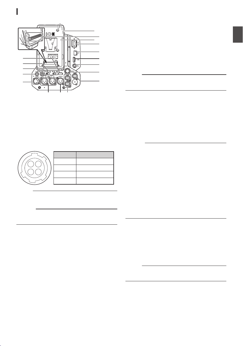
Rear Terminal
.
M
L
N
P
J
I
K
D
E
B
A
C
O
Q
GHF
R
A
Back Tally Lamp (Rear)
(A P46 [Tally Lamp] )
(A P222 [Blinking of the Tally Lamp] )
B
[AUDIO INPUT1/2] Switch
(A P69 [Audio Recording] )
C
[DC OUT] Terminal (Rear)
Supplies power to an externally-connected
wireless receiver.
.
14
23
1
2
3
4
UNREG GND
NC
NC
UNREG +12V
Signal Name
Pin Number
Memo :
0
The pin configurations for C and K are the
same.
Caution :
0
Do not connect it to any device other than an
external wireless receiver.
D
[PHONE] Terminal (Φ3.5 mm)
(A P181 [Connecting the Headphone] )
E
[DC INPUT] Terminal
Input terminal for DC 12 V power supply. For
connecting a separately sold AC adapter.
(A P33 [Using AC Power (DC IN Power)] )
F
[AUDIO INPUT1/2] Terminal (XLR 3-pin)
G
[AUDIO OUT] Terminal (XLR 5-pin)
Outputs audio signals of AUDIO CH1/CH2 or
CH3/CH4.
Audio signals are output according to the
setting in [A/V Set] B [Audio Set] B [AUDIO
OUT Ch.].
H
[HD/SD SDI OUT1/2] Terminal
(A P179 [Connecting External Monitor] )
I
[HD/SD SDI IN] Terminal
(A P182 [Inputting External Synchronizing
Signals (Genlock)] )
J
[REMOTE] Terminal
(A P180 [Connecting a Remote Control Unit] )
K
[DC OUT] (LAN) Terminal
Supplies power to devices such as a mobile
router that is connected to the [LAN] terminal.
Memo :
0
The pin configurations for C and K are the
same.
L
[HDMI] Output Terminal
(A P179 [Connecting External Monitor] )
M
[LAN] Terminal
For connecting the LAN cable.
N
[HOST] USB Host Terminal
For connecting a USB adapter according to the
intended purpose when you are connecting the
unit to a network.
Caution :
0
When [System] B [Record Set] B [Record
Format] B [System] is configured to “High-
Speed”2, network cannot be used via
wireless LAN u v or the [HOST] terminal
(USB). Configure as follows in this case.
0
Set
[Network] B [Connection Setup] B [USB/
Int. WLAN] to “Off”. u v
0
Unplug the USB network adapter
Note that camera operation will come to an
emergency
stop and the power will turn off if the
above steps are not performed.
File data may be damaged if this happens while
recording is in progress.
O
Battery Loading Folder
The shape varies across the U and E models.
* The E model is used in the illustration here.
(A P34 [Using a Battery Pack] )
P
Expansion Unit Terminal
Terminal for connecting a FS-790 (sold
separately) or other units.
Memo :
0
Remove the battery loading folder when using
this terminal.
Q
D-TAP terminal (IDX)v x
R
D-TAP terminal (Anton/Bauer)u w
Names of Parts
27
Introduction

Electronic Viewfinder u v
(A P42 [Adjusting the Viewfinder] )
.
A
D
B
C
F
E
L MJ K
O NQ P
G
H
I
A
Microphone Holder Lock Knob
B
Microphone Holder
C
Front Tally Lamp
(A P
46 [Tally Lamp] )
(A P222 [Blinking of the Tally Lamp] )
D
Eyepiece Focus Ring
For adjusting the visibility.
E
Electronic Viewfinder
F
Eyepiece
Prevents external light from entering the
viewfinder screen and cameraman’s vision.
G
[USER1] Button (VF)
It can be assigned with a specific menu function.
Initial setting: VF Display
(A P45 [Assignment of Functions to User
Buttons] )
H
[USER2] Button (VF)
It can be assigned with a specific menu function.
Initial setting: Expanded Focus
(A P45 [Assignment of Functions to User
Buttons] )
I
Slide Stopper
Use it when mounting or unmounting the
viewfinder.
J
[MIRROR] Switch
Flips the image.
L/R: Flips horizontally; OFF: Normal display; B/
T: Flips vertically
K
[B.LIGHT] Switch
For configuring the brightness of the viewfinder.
H: Bright; N: Normal; L: Dark
L
[ZEBRA] Switch
Displays the zebra pattern.
ON: Turns on zebra pattern; OFF: Turns off
zebra pattern; MOMENT: “Turns on zebra
pattern” for a specific time interval while the
switch is being pressed.
M
[TALLY
] Front Tally Switch
For configuring the front tally lamp.
HIGH: Bright; OFF: Light off; LOW: Dark
(A P46 [Tally Lamp] )
(A P222 [Blinking of the Tally Lamp] )
N
[BRIGHT] Knob
For adjusting the brightness of the viewfinder.
O
[CONTRAST] Knob
For adjusting the contrast of the viewfinder.
P
[CHROMA] Knob
For adjusting the color of the viewfinder.
Q
[PEAKING] Knob
For adjusting the outline of the viewfinder.
28
Names of Parts
Introduction
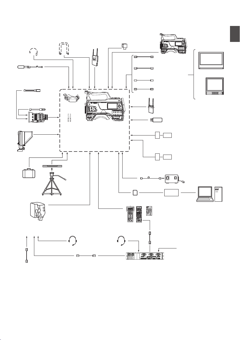
Basic System Diagram
.
OPERATE LOCK
OFF FULL
MODE
RM-LP20
REMOTE CONTROL UNIT
GAINSHUTTER
NORMAL
1/120
1/100
1/250
1/500
1/1000
1/2000
EEI
0dB
+3dB
+6dB
+9dB
+12dB
+18dB
ALC
LEVEL GAMMA LEVEL GAMMA KNEE POINT
AUTO
KNEE
WHITE BALANCE
MANUAL PRESET FAW AW A AW B
WHITE PAINT
RB
PAINT AUTO WHITE
TALLY
CALL PREVIEW
MASTER BLACK
IRIS
AUTO
MANUAL
CLOSE OPEN
XLR 4-pin
(DUO-150)
FS-900BS
RM-FP790
VC-P790RMG
RM-LP20G
RM-LP25U/RM-LP55U
FS-900CAM
KA-F790
: KA-PW790AG
: KA-PW790VG
[AUDIO
INPUT
1/2]
[REMOTE]
[UniSlot]
[MIC IN]
[PHONE] [SDI IN]
[SDI OUT]
HZ-FM13(FUJINON)
HZ-FM15(CANON)
HZ-ZS13B
EVF
2/3
KA-551U
[HOST]
(Digital 150)
[LIGHT]
(IDX)
Carrying
Case
Tripod
AC Adapter
U model
E model
U model
E model
Focus Manual Controller
Zoom Lens
Shoulder Belt Wireless
Microphone
Receiver
Video Light Camera
Recorder
Headphone
SDI Cable BNC
Composite
Cable BNC
Microphone
Monitor
Monitor
HeadsetHeadset
Zoom Servo
Controller
LCD Studio
Viewfinder
Tripod Base
Fiber Camera Unit
Power Wafer
Remote Control Unit
Camera Remote Interface
Cable
Fiber Camera Remote Control
Unit
Fiber Cable
Composite Video Out for
Teleprompter
RTS/Clear-COM
Interface
Audio cable XLR
HDMI Cable
UniSlot Wireless Receiver
USB Network Adapter
Battery Charger
Battery Charger
Battery
Battery
Remote Control Unit
Battery Mount
Wireless LAN Antenna u v
E model: V Mount
U model: Gold Mount
Standard Package
SD Card SD Card Reader
(Anton/Bauer)
Basic System Diagram
29
Introduction
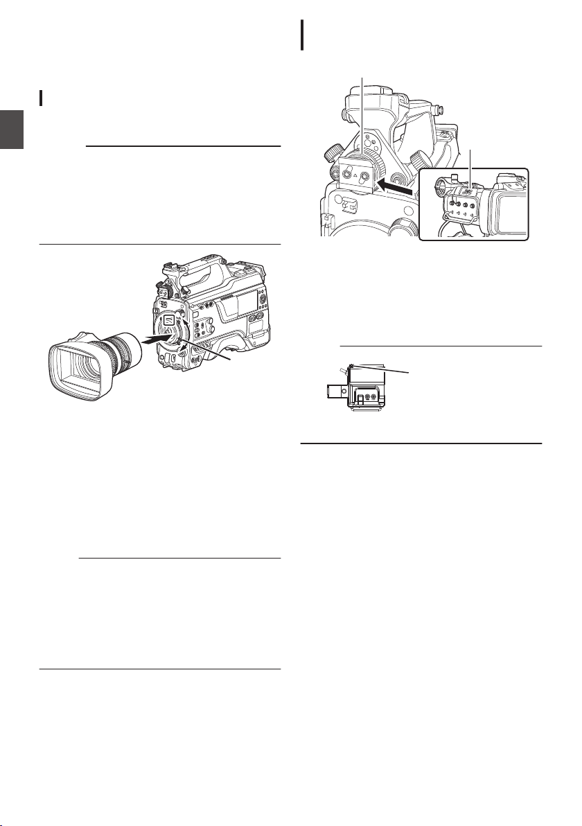
Settings and Adjustments
Before Use
.
Attaching the Lens (Sold Separately)
This camera recorder can be attached with a B4
mount lens.
Caution :
0
Check that the camera recorder is turned off
before
attaching
the lens. Attaching the lens with
the power turned on can result in accident and
malfunction.
0
When detaching the lens, do not touch the
optical filter or allow dust to adhere to the optical
filter.
.
1,4
3
1
Loosen the lens lock lever.
2
Detach the body cap.
0
Do not lose the body cap, keep it properly.
3
Attach the zoom lens such that the pin
matches the hole of the mounting area.
4
Tighten the lens lock lever.
5
Connect the lens cable to the [LENS]
terminal.
6
Attach the lens cable to the clamp.
Memo :
0
Tighten
the lens lock lever completely. If it is not
fully tightened, the lens may drop or the back
focus may be out of alignment.
0
For details on the lens, please refer to the
“INSTRUCTIONS” of the lens used.
0
It is necessary to adjust the back focus before
use.
(A P44 [Adjusting the Back Focus] )
Attaching the Viewfinder (Supplied)
u v
.
2,4
3
1
Set the [POWER ON/OFF] switch of the
camera recorder to “OFF”.
2
Loosen the viewfinder left-right position
lock ring.
3
Slide the viewfinder in the direction of the
arrow to attach it.
Memo :
.
Slide Stopper
0
To detach the viewfinder, pull the slide stopper
up and slide it in opposite direction of the arrow.
4
Turn the viewfinder left-right position lock
ring to secure the position of the
viewfinder.
5
Attach the viewfinder cable to the [VF]
terminal.
6
Pin the viewfinder cable to the clamp.
30
Settings and Adjustments Before Use
Preparations
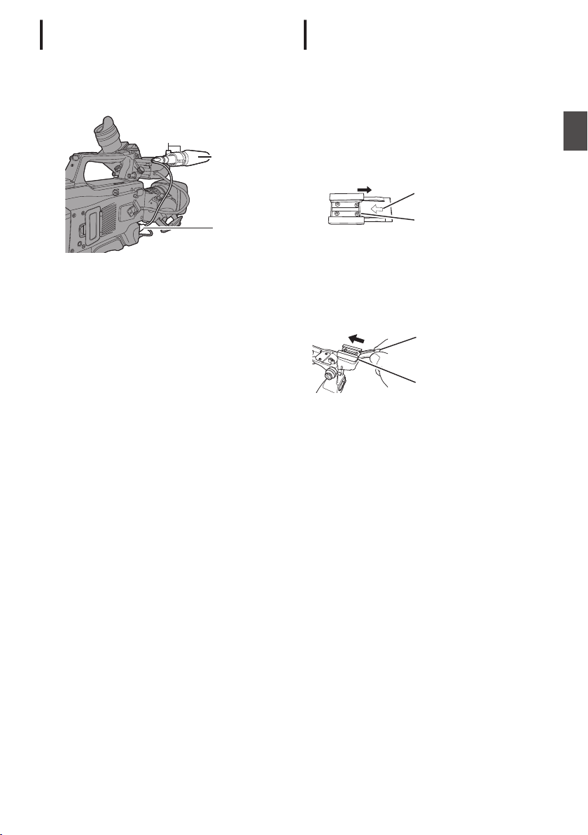
Attaching the Microphone (Sold
Separately)
You can attach a separately sold microphone to the
microphone holder.
The microphone that is sold separately uses a
phantom power supply.
.
4
1, 3
2
1
Turn the knob on the microphone holder
counterclockwise to loosen and open the
microphone holder.
2
Place the microphone in the microphone
holder.
3
Turn the knob on the microphone holder
clockwise to secure the microphone.
4
Connect the microphone cable to the [MIC
IN
] terminal.
5
Pin the microphone cable to the clamp.
6
Perform the settings for the phantom mic
correctly.
(A P69 [Audio Recording] )
Attaching the Video Light (Sold
Separately)
Video lights or accessories can be attached to the
accessory shoe of this camera recorder.
The accessory shoe is of the 1/4-inch screw type.
To make use of a slide shoe, attach the supplied
cold shoe unit.
Attaching the Cold Shoe Unit
1
Remove the plate from the cold shoe unit.
While lifting the catch, slide the plate out.
.
Catch
Plate
2
Attach the cold shoe unit to the shoe of this
camera recorder using the four screws
supplied.
3
Attach the plate to the cold shoe unit.
Push the catch up from the bottom and slot the
plate into the guide in the direction of the arrow.
.
Guide
Plate
Attaching the Video Light
The [LIGHT] terminal (D-tap) of this camera
recorder can be connected with a video light (DC
12 V, maximum power consumption 50 W u
w x and DC 12V, 2A v).
Connect the [LIGHT] terminal after attaching the
accessory shoe.
When the [LIGHT] switch is set to “AUTO”, the light
goes on only during recording in tandem with the
camera. When it is set to “MANUAL”, the light goes
on or turns off respectively when the video light
power is turned on or off.
Settings and Adjustments Before Use
31
Preparations
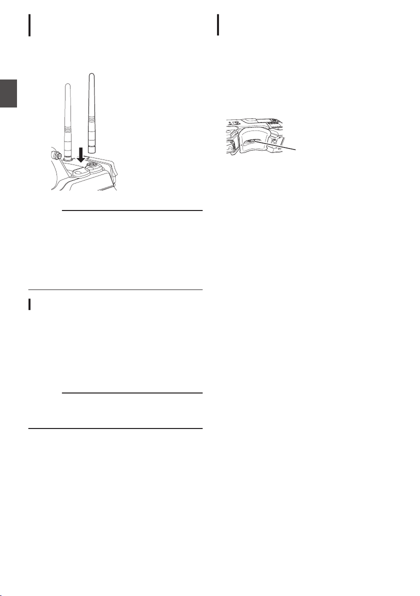
Attaching the Wireless LAN Antennas
(Supplied) u v
Attach the wireless LAN antenna by turning it in the
clockwise direction. Hold the base while attaching
the antenna.
.
Caution :
0
Applying force to the wireless LAN antenna or
yanking it may damage the antenna so please
use caution when using the antenna.
If it is damaged, replacement is chargeable even
during the warranty period.
(Part number: T9A-0095-00)
0
Use the antenna holders without removing
them.
Attaching the Tripod (Sold Separately)
Mount this camera recorder after attaching the
KA-551U tripod base unit (sold separately) to the
tripod.
To prevent the camera recorder from falling off,
which may result in injuries or damages, read the
“INSTRUCTIONS” of KA-551U as well as that of
the tripod to be used to attach the camera recorder
securely.
Caution :
0
If the camera recorder exceeds the weight limit
of the tripod, do not mount it on the tripod.
0
Use the tripod on a stable surface.
Adjusting the Position of the Shoulder
Pad
Adjust the position of the shoulder pad back and
forth.
1
Release the lock of the lock lever and adjust
the position of the shoulder pad back and
forth.
2
Lock the lock lever and check that the
shoulder pad is fixed.
.
Lock Lever
32
Settings and Adjustments Before Use
Preparations
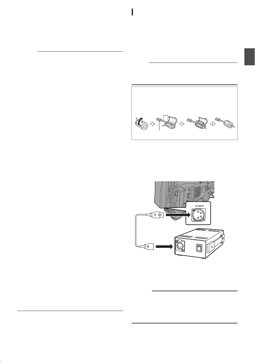
Power Supply
To use this camera recorder, you can attach a
battery pack or connect an AC adapter to it.
(A P34 [Using a Battery Pack] )
(A P33 [Using AC Power (DC IN Power)] )
Caution :
0
Set the [POWER ON/OFF] switch to “OFF”
before changing the power supply that operates
this camera recorder.
0
Use the camera recorder and peripheral
equipments within the rated output of the AC
adapter.
0
To connect other peripheral equipment, do so
under the following conditions.
0
Keep the total power consumption of the
peripheral equipments under 35 W when
using the recommended battery.
0
Keep the total power consumption of the
peripheral equipments under 65 W when
using Tandem 150 (recommended AC
adapter). u w
0
Keep the total power consumption of the
peripheral equipments under 50 W when
using AC-100 (recommended AC adapter).
x
0
The power consumption of the [LIGHT] terminal
is below 50 W. Keep the total power
consumption of the peripheral equipments
excluding the [LIGHT] terminal under 35 W
when using the terminal. If the total power
consumption of the peripheral equipments
exceeds the rating, the power to the [LIGHT],
[DC OUT] (rear) and [DC OUT] (LAN) terminals
is automatically cut off. This is not a malfunction.
Use peripheral equipments with lower power
consumption then turn on the power of this
camera recorder again. u w x
0
To check the power consumption, refer to the
Power screen of the Status screen.
(A P171
[Power Screen] )
0
If the voltage of the [DC INPUT] becomes 12 V
or less, the USB adapter connected to the
[HOST] terminal cannot be used. Check the
power supply and the peripheral equipments,
and turn on the power of this camera recorder
again.
0
Use
a power supply of 12 V/ 2A or below for the
[LIGHT] terminal.
The [LIGHT] terminal, DC OUT terminal
(rear)/DC OUT (LAN) terminal and the D-tap
terminal of the battery loading folder cannot be
used at the same time. v
Using AC Power (DC IN Power)
Use the AC adapter (sold separately) to operate
the camera recorder with AC power.
Recommended AC Adapter
u w : Tandem 150 (Anton/Bauer)
v
: IA-300a (IDX)
x
: AC-100 (IDX)
Memo :
0
For the type of AC adapter to be attached on a
battery mount, check the method of attachment
in [Using a Battery Pack] (A P 34).
o
Attaching Core Filter Beforehand v
Attach the core filter (large) to the DC cable of the
AC adapter before using the AC adapter.
.
Release the
stopper.
To be connected to the AC Adapter.
5 cm
Wind twice
1
Connect the DC cable of the AC adapter to
the [DC INPUT] terminal of the camera
recorder.
Check that the power of this unit and that of the
AC adapter are both set to “OFF”, followed by
connecting according to the diagram.
.
2
Turn on the power of the AC adapter,
followed by setting the [POWER ON/OFF]
switch of this unit to “ON”.
Power will be supplied to the camera recorder.
Caution :
0
Do not insert or remove the DC cable during
recording.
0
Do not use power supply of high voltage
fluctuation, containing noise such as ripple, or
with insufficient capacity.
Power Supply
33
Preparations
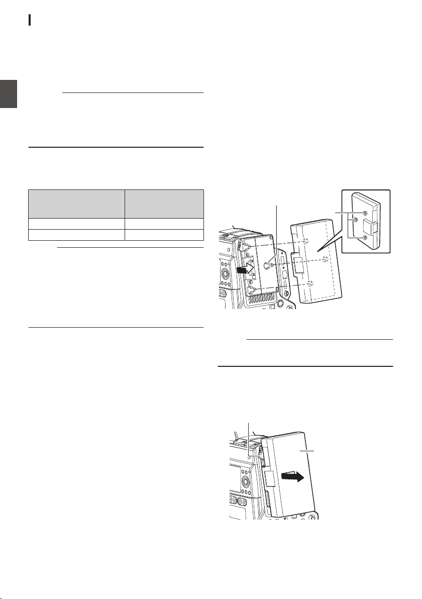
Using a Battery Pack
Recommended Batteries
U model : Digital 150 (Anton/Bauer)
E model : DUO-150 (IDX)
* Models with an E suffix are for the European
market and the UL Listing mark is not applicable.
Caution :
0
Make
use
of the recommended batteries. Heavy
batteries may fall off if not used correctly.
0
For details on how to charge the battery, please
refer to the “INSTRUCTIONS” of the battery in
use.
Battery Operating Time
The following are the approximate times for
continuous operation on fully-charged batteries.
Battery
Continuous
Recording Time (At
25 °C)
Digital 150 (U model) Approx. 3.1 hrs
DUO-150 (E model) Approx. 3.1 hrs
Memo :
0
Actual operating times may differ depending on
the age of the battery, charging condition, and
operating environment.
0
Operating time is shortened in cold
environment.
0
The operating time may shorten when power
zoom is used, accessories are connected, or
when the LCD monitor is frequently used.
Precautions for the Battery Operation
0
Do not remove the battery when the [POWER
ON/OFF] switch is “ON”.
0
Do not insert or remove the DC cable when the
battery is in use.
0
Leaving the camera recorder unused with the
battery attached will deplete the battery power
even when you set the
[POWER ON/OFF]
switch to “OFF”. Remove the battery if you are
not using the camera recorder.
Attaching/Detaching the Battery (U Model)
Use the following battery type.
0
Gold Mount
1
Align the battery guide pins (x3) with the
battery adapter guide hole, and insert them
directly.
.
Guide Pins
Guide Hole (x3)
2
Slide the battery in the direction indicated
by the arrow until a “click” sound is heard.
Memo :
0
If the guide pins are not inserted straight, the
battery will not be attached correctly.
3
Detaching the Battery
Press down the release lever and slide the
battery toward you to detach it from the camera
recorder.
.
Battery
Release Lever
34
Power Supply
Preparations
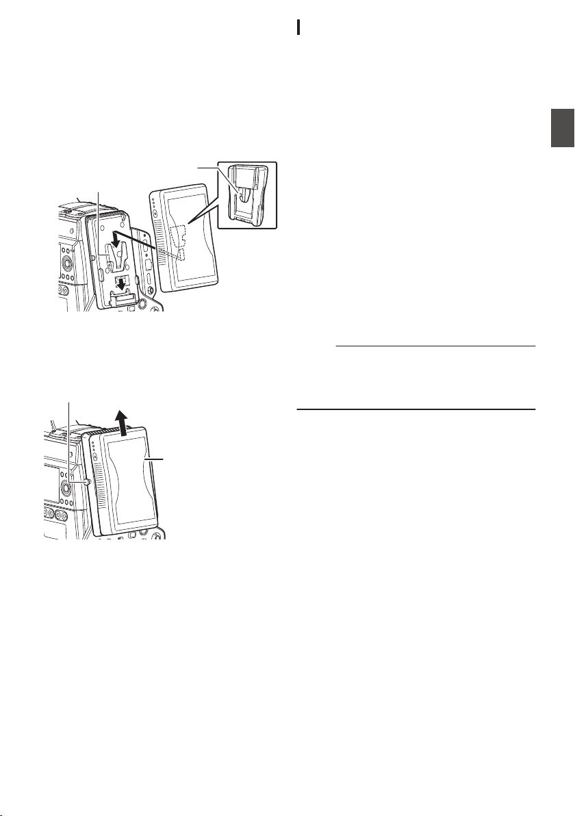
Attaching/Detaching the Battery (E Model)
Use the following battery type.
0
V Mount
1
Attach the battery.
Face the terminal downward and attach the V
mount of the battery onto the V mount
attachment bracket of the camera recorder.
2
Press down the battery until it snaps into
place.
.
V Mount
V Mount
Attachment Bracket
3
Detaching the Battery
Press down the release lever and slide the
battery upward to detach it from the camera
recorder.
.
Battery
Release Button
Precautions for Batteries
0
Store the battery in a cool and dry place when
not in use. Do not expose the battery to high
temperatures (such as in a car under direct
sunlight). This will cause battery leakage and
shorten the battery life.
0
Operating time is shortened if the battery
terminal is dirty.
0
If the operating time shortens drastically even
after charging, the battery may be reaching the
end of its life. Replace the battery with a new
one.
Battery Warning Settings
Follow the steps below to configure the warning
voltage or warning level when the remaining
battery level is running low.
1
Select “Voltage” or “Capacity%” in
[System]
B [Battery] B [Type
]
0
“Near End (V)
” and “End (V)” are enabled
when “Voltage” is selected.
0
“
Near End (%)” and “End (%)” are enabled
when “Capacity%” is selected.
2
Configure “Near End” and “End”
0
Configures the setting at which the power is
shut down automatically after the warning is
activated.
(A P149
[ Near End (V) 0 ] )
(A P149 [ End (V) 0 ] )
(A P149 [ Near End (%) 2 ] )
(A P149 [ End (%) 2 ] )
3
Check in advance to ensure that the
connected battery is in order and the
settings are appropriate
0
If the time is different from what has been
anticipated, repeat the steps in 2 and 3.
Memo :
0
When the battery that is connected does not
support communication, “Near End (V)” and
“End (%)” are enabled even when “Capacity%”
is selected.
Power Supply
35
Preparations
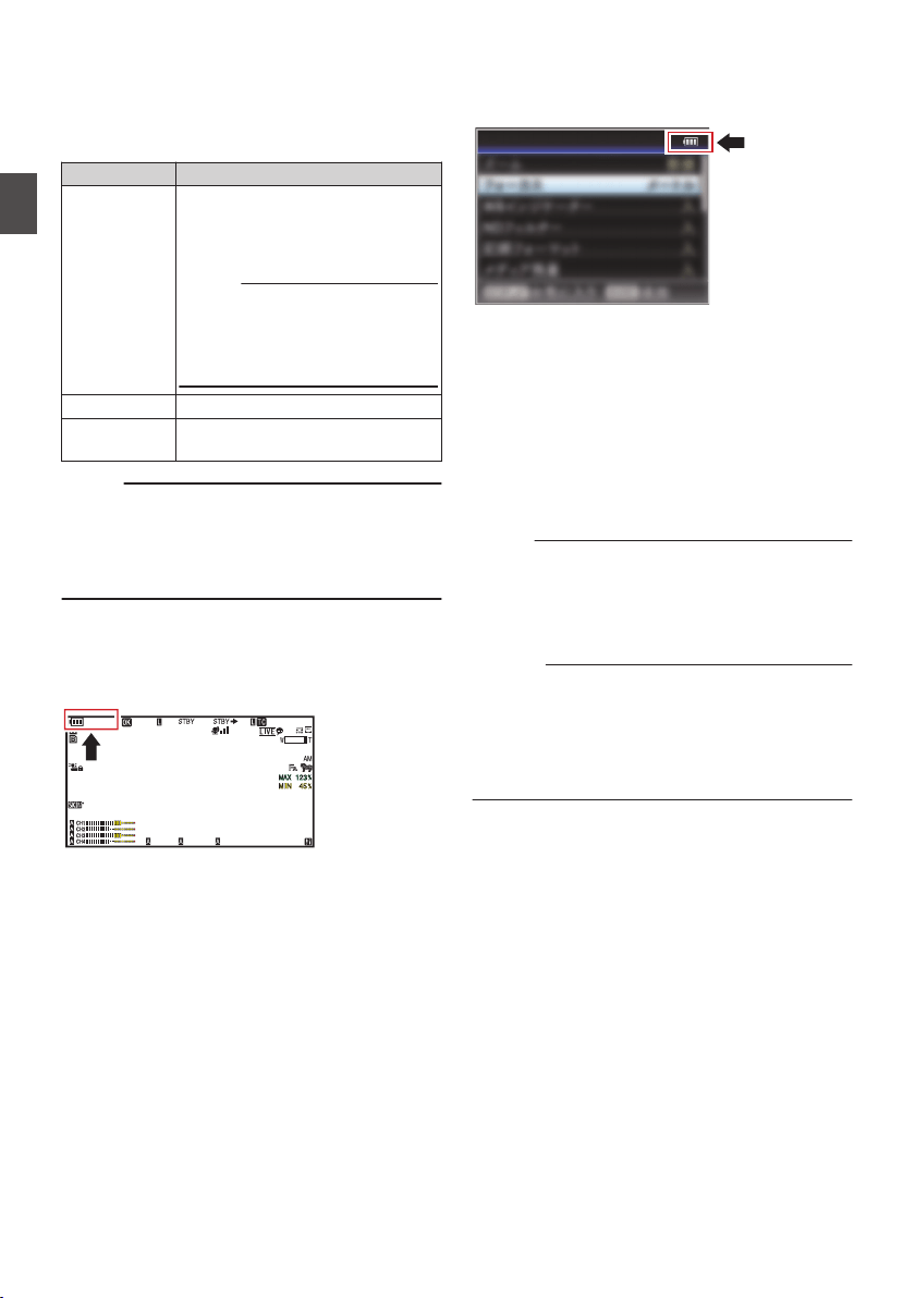
Power Status Display
Viewfinder Screen and LCD Monitor
The power status is displayed on the display and
menu screens.
Display Description
B 14.4V
B 100min
C 30%
4 RES
Currently powered by a battery.
When the battery power runs out,
the battery mark appears hollow,
and “RES” (yellow) is displayed.
Memo :
0
You can set the display using
[LCD/VF] B [Display Type] B
[Battery].
(A
P129 [ Battery ] )
G
Currently powered by DC power.
H
A warning display when the supply
voltage of the DC power is low.
Memo :
0
The battery mark that indicates the battery level
may not appear depending on the battery in use.
0
When the battery that is connected does not
support communication, the voltage is
displayed regardless of the setting.
Display Screen
(A P161 [Display Screen in Camera Mode] )
(A P167 [Display Screen in Media Mode] )
.
100min
50min
282min
1
/60
F2.8
AE
±0
ND1
/64
12 :34 :56
ISO
102400
00:00:00.00
1080 /30p
SDI IN
ITU709
COMPRESS
5 . 6 f t
B 5600
K
Menu Screen
(A P106 [Display and Description of the Menu
Screen] )
.
Display Settings
Warnings by Lamp and Warning Tone
Warning status is indicated by tally lamp and
warning tone.
0
The front and back tally lamps of the camera
recorder appear blinking.
0
The warning tone is output from the speaker or
[PHONE] terminal.
Adjust the volume level using the [ALARM]
volume adjustment knob.
Memo :
0
If you continue to use the camera recorder while
the power warning is displayed, the camera
recorder will stop automatically when the battery
or supplied voltage from the DC power becomes
lower.
Caution :
0
The remaining battery power and time are
displayed as they are from the battery
information.
Accurate data may not be displayed
depending on the battery condition. Replace the
battery as soon as possible when the remaining
battery power and time are low.
36
Power Status Display
Preparations
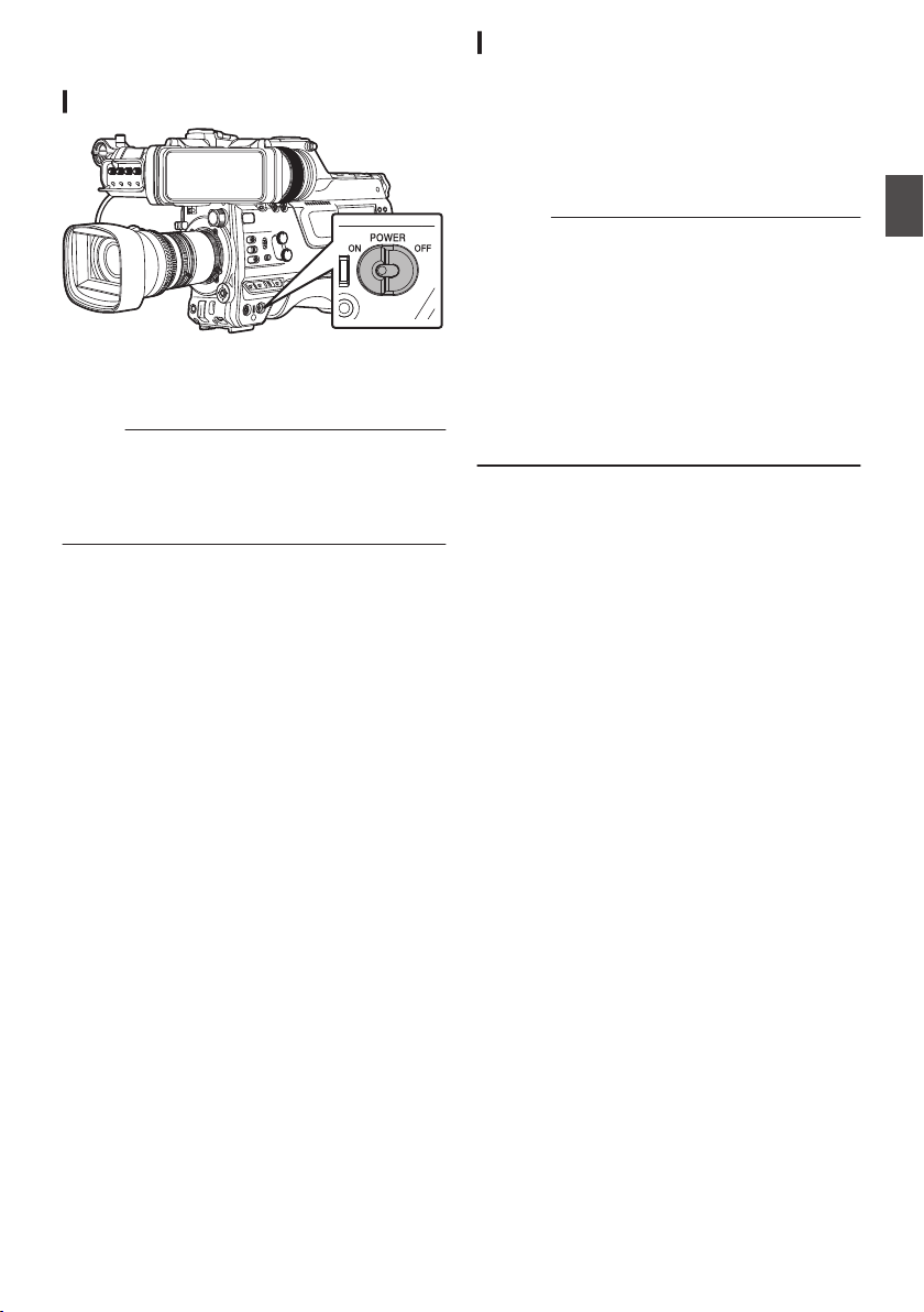
Turning On/Off the Power
Turning On the Power
.
1
Set the [POWER ON/OFF] switch to “ON”.
The camera recorder starts up in Camera mode
and is ready for shooting.
Memo :
0
The camera recorder always start up in Camera
mode when the [POWER ON/OFF] switch is set to
“ON”. Use the [CAM/MEDIA] button at the side of
the camera recorder to switch mode.
(A P20 [Operation Modes] )
Turning Off the Power
Sets the camera recorder to the recording standby or
stop mode.
1
Set the [POWER ON/OFF] switch to “OFF”.
2
Remove the battery and the power to the [DC
INPUT] terminal (when not in use for a long
time).
Caution :
0
Do not set the [POWER ON/OFF] switch to “OFF”
during recording. Check that the operation mode
display is “STBY” or “STOP” before you turn off the
power.
0
If you have mistakenly set the [POWER ON/OFF]
switch to “OFF” during recording, wait for 5
seconds or more before you turn on the power
again.
0
When turning off the power, first set the [POWER
ON/OFF] switch of the camera recorder to “OFF”.
Do not remove the battery or turn off the AC power
while the [POWER ON/OFF] switch is set to “ON”.
Turning On/Off the Power
37
Preparations
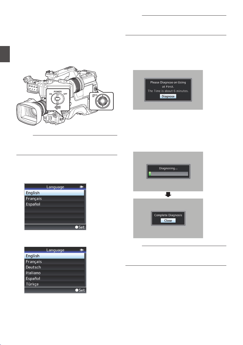
Initial Settings
When the power is first turned on, the Initial Setting
screen for performing the initial settings in the
camera recorder appears.
Set the date/time of the built-in clock in the [Date/
Time] screen.
All operations are disabled until initial settings are
complete.
.
Memo :
0
It is recommended to use the AC adapter as the
power supply.
0
Attach the lens cap.
1
Set the [POWER ON/OFF] switch to “ON”.
A language selection screen appears.
0
For U models
.
0
For E models
.
Memo :
0
The menus and messages on the screen of the
LCD monitor or viewfinder are displayed in the
selected language.
2
Select a language using the cross-shaped
button (
JK), and press the
[STATUS/SET]
button (
R).
A self-diagnosis screen appears.
.
3
Ensure the lens cap is attached, and press
the [STATUS/SET
] button (
R).
0
Self-diagnosis starts.
0
A progress bar appears, and “Complete
Diagnosis” appears when the diagnosis is
complete.
.
Memo :
0
It takes about 6 minutes to complete the
diagnosis. During the diagnosis, do not operate
or turn off the camera recorder.
38
Initial Settings
Preparations
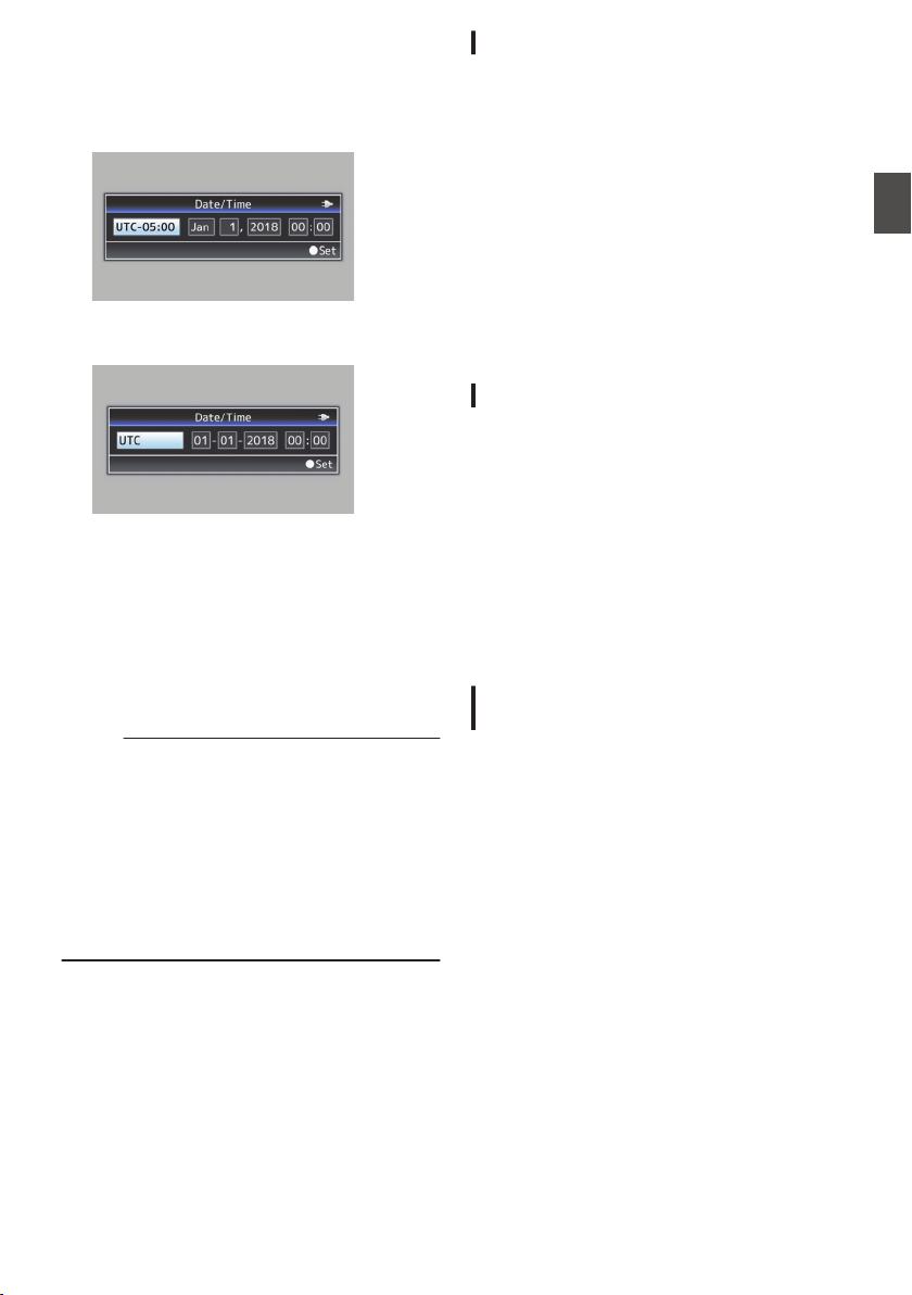
4
Press the [STATUS/SET] button (
R) after
confirming the exit screen.
The [Date/Time] screen appears.
0
For U models
.
0
For E models
.
5
Set the time zone and date/time.
A
Move the cursor with the cross-shaped button
(HI) and select the setting item.
B
Change the values with the cross-shaped
button (JK).
6
Press the [STATUS/SET] button (
R) after
setting is complete.
The clock is set to 0 seconds of the input date/
time.
Memo :
0
The configured date/time data can be displayed
on the LCD monitor and viewfinder screen and
be recorded to a recording media.
0
The value of the year can be set in the range of
“2000” to “2099”.
0
The configured date/time data is saved in the
built-in battery even if the power is turned off.
0
If the date/time data is no longer retained, the
built-in battery is dead. For replacement of the
built-in battery, please contact the local dealers
in your area.
Changing the Time after Initial Setting
Setting the Date/Time
(A P149 [ Date/Time ] )
1
Select [System]
B [Date/Time
].
The [Date/Time] screen appears.
2
Set the date and time.
A
Move the cursor with the cross-shaped button
(HI) and select the setting item.
B
Change the values with the cross-shaped
button (JK).
3
Press the Set button (
R) after setting is
complete.
The clock is set to 0 seconds of the input date/
time.
Changing the Display Style
You can change the display style of the date/time
on the menu.
Setting the Date Display (Date Style)
(A P
150 [ Date Style ] )
The date display can be changed in [System] B
[Date Style].
Setting the Time Display (Time Style)
(A P
150 [ Time Style ] )
The time display can be changed in [System] B
[Time Style].
Date/Time Display in Each Operation
Mode
During Camera mode:
Time of the built-in clock is displayed.
During Media mode:
Shooting date/time of the clip being played back is
displayed.
Initial Settings
39
Preparations
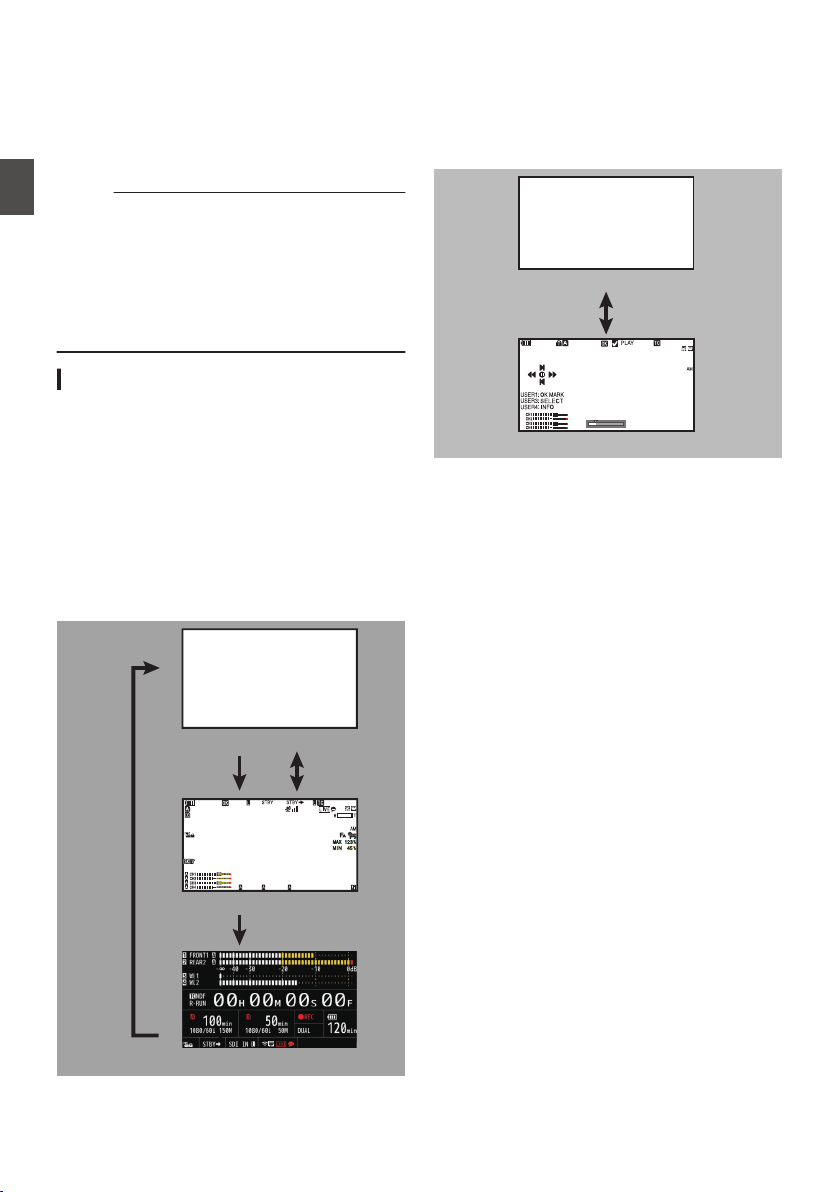
Displays on the LCD
Monitor and Viewfinder
You can display the camera status, recording
media information, zebra pattern, and various
markers in the video image on the LCD monitor and
viewfinder screen during shooting.
Memo :
0
When [A/V Set] B [Video Set] B [SDI OUT2
Char.]/[HDMI Char.]/[Video OUT Char.] is set to
“On”, the display screen and menu screen are
also displayed in the video image of the video
signal output terminal.
(A P131
[ SDI OUT2 Char. ] )
(A P131 [ HDMI Char. ] )
(A P131 [ Video OUT Char. ] )
Display Screen
Display Screen (VF/LCD) in Camera Mode
(A P161 [Display Screen in Camera Mode] )
0
Use the [DISPLAY] button to switch the display
mode of the LCD monitor.
(Display off B Display on B Enlarged display B
Display off)
0
Use the user button that is assigned with “VF
Display” to switch the viewfinder screen.
(Display off B Display on B Display off)
0
Press
the
[STATUS/SET] button to switch to the
status screen.
.
100min
50min
282min
1
/60
F2. 8
AE
±0
ND1
/64
12 : 34: 56
ISO
102400
00: 00: 00.00
1080 /30p
SDI IN
ITU709
COMPRESS
5 . 6 f t
B 5600
K
Display Off
Electronic
Viewfinder
Display On
Enlarged Display
LCD
Monitor
Display Screen (VF/LCD) in Media Mode
(A P167 [Display Screen in Media Mode] )
0
This is the screen display during clip playback in
Media Mode.
0
The display switches with every press of the
[DISPLAY] button.
(Display off B Display on B Display off)
.
Jan 24,2018
1920x1080
30p 50M
282min
12 : 34: 56
00: 00: 00.00
1000/2000
Display Off
Display On
40
Displays on the LCD Monitor and Viewfinder
Preparations
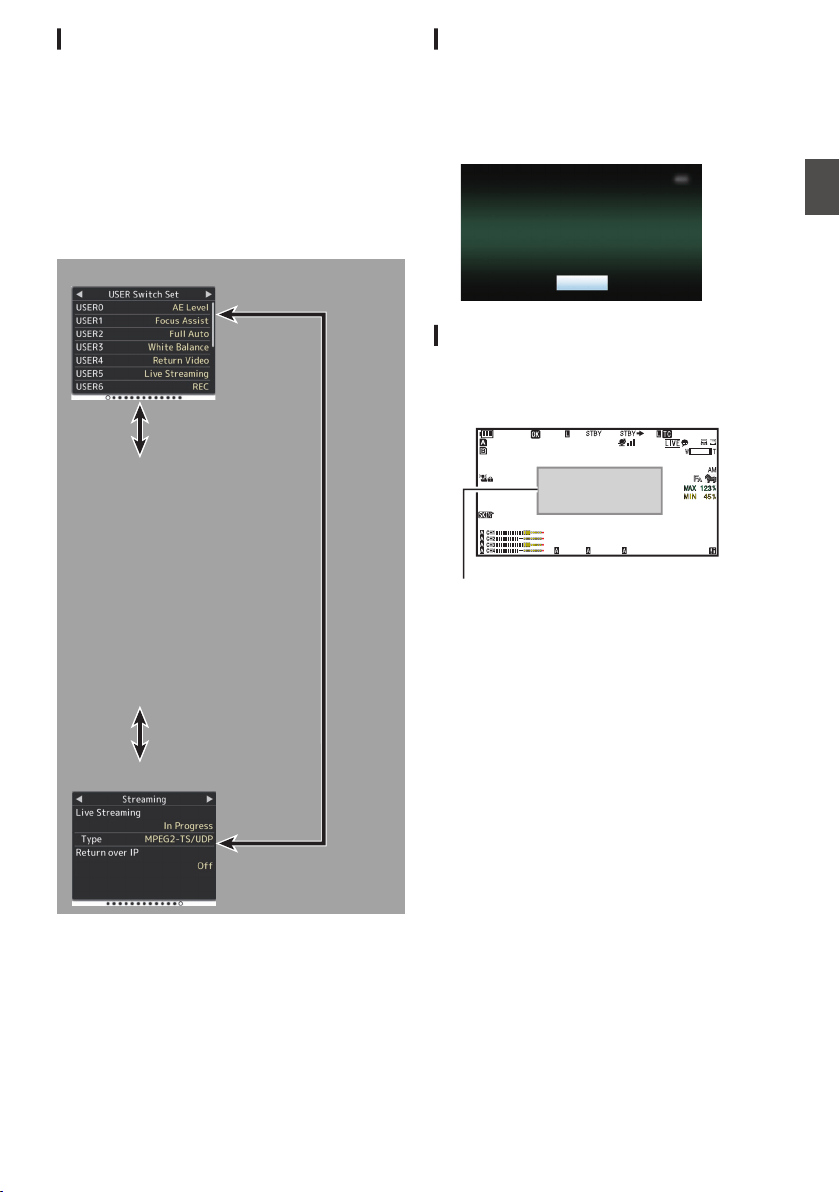
Status Screen
0
This screen allows you to check the current
settings.
0
To display the status screen, press the
[STATUS/SET] button in the normal screen.
0
Press the [STATUS/SET] button to switch to the
status screen.
0
Press the [MENU/THUMB] button at each status
screen (other than the [Camera] and [Power]
screen) to enter the setting screen.
0
Use the cross-shaped button (HI) to switch
between the screens.
.
USER Switch Set
Camera
LCD/VF
Record Format
Audio Input
Audio Output
Video
Power
Planning Metadata
Network
LAN
USB/Int. WLAN uv
USB wx
Streaming
* These are screen examples. The contents
displayed are different depending on the model
and settings.
Remote Edit Mode Screen
This is a mode for accessing the page for editing
the metadata that is recorded in a clip via a web
browser on devices such as a smartphone, tablet
terminal, or PC.
(A P196 [ Clip Metadata ] )
.
Exit
Remote Edit Mode
Warning Display
Warning display is displayed in the display screen
(Camera mode, Media mode).
(A P218 [Error Messages and Actions] )
.
100min
50min
282min
1
/60
F2.8
AE
±0
ND1
/64
12 :34 :56
ISO
102400
00: 00:00.00
1080 /30p
SDI IN
ITU709
COMPRESS
5 . 6 f t
B 5600
K
Warning Display Area
Displays on the LCD Monitor and Viewfinder
41
Preparations
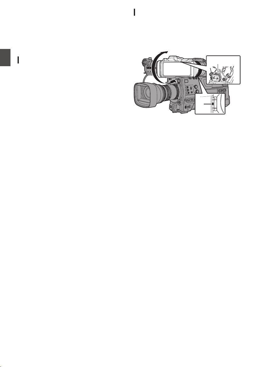
Adjusting the LCD Monitor
and Viewfinder
You can monitor video images on this camera
recorder using the viewfinder, LCD monitor, or
both.
Adjusting the LCD Monitor
You can change the brightness of the LCD monitor
according to your usage condition.
Changing the brightness of the screen will not
affect the recorded images.
Adjusting the Brightness
Use [LCD/VF] B [LCD Bright] to adjust the
brightness of the LCD monitor.
(A P125 [ LCD Bright ] )
Adjusting the Outline
Use [LCD/VF] B [LCD Peaking] to adjust the
outline of the LCD monitor.
(A P125 [ LCD Peaking ] )
Adjusting the Contrast
Use [LCD/VF] B [LCD Contrast] to adjust the
contrast of the LCD monitor.
(A P125 [ LCD Contrast ] )
Adjusting the LCD RGB Gain
Use [LCD/VF] B [LCD RGB Gain] to adjust the
R/G/B gain of the LCD monitor.
(A P126 [ LCD RGB Gain ] )
Configuring the Backlight
Configure the backlight using the [B.LIGHT] button
located on the side operation panel.
Dark B Normal B Bright B Off B Dark
Adjusting the Viewfinder
You can change the brightness and peaking of the
viewfinder screen according to your usage
conditions.
Changing the brightness of the screen will not
affect the recorded images.
.
3
1
2
2
4
1
Loosen the fastening rings on the left and
right sides of the viewfinder to adjust the
horizontal position, followed by tightening
the rings.
2
Loosen the viewfinder front-back position
lock ring. Adjust the front and back
positions then tighten the ring.
3
Adjust the angle of the viewfinder to a
position that enables easy viewing.
4
Adjust the visibility using the eyepiece
focus ring.
Adjust until the viewfinder image appears
sharp.
42
Adjusting the LCD Monitor and Viewfinder
Preparations
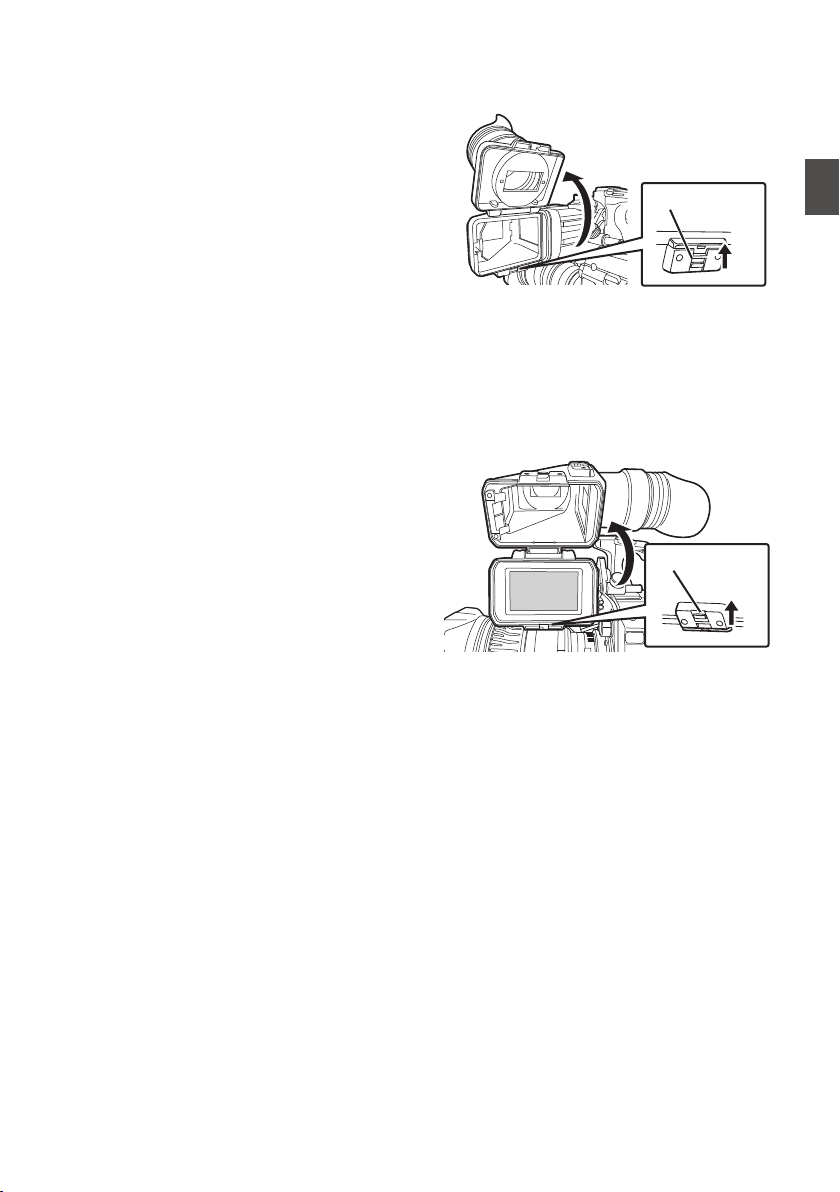
5
Adjust the brightness, outline and contrast
of the viewfinder screen.
Adjusting the Brightness
Use the [BRIGHT] knob to adjust the brightness
of the viewfinder.
Adjusting the Outline
Use the [PEAKING] knob to adjust the outline of
the viewfinder.
Adjusting the Contrast
Use the [CONTRAST] knob to adjust the
contrast of the viewfinder.
Adjusting the Color
Use the [CHROMA] knob to adjust the color of
the viewfinder.
Configuring the Luminance
Use the [B.LIGHT] switch to configure the
luminance level.
H: Bright; N: Normal; L: Dark
Adjusting the VF RGB gain
Use [LCD/VF
] B [VF RGB Gain] to adjust the R/
G/B gain level of the viewfinder.
(A P126 [ VF RGB Gain ] )
Displaying in Black and White
The display can be switched to black-and-white
by configuring [LCD/VF] B [VF Color] to “Off”.
(A P125 [ VF Color ] )
o
Flipping up the Eyepiece
Flipping
up the eyepiece provides a better view
of the entire image.
Push the lock upward to flip up the eyepiece.
.
Lock
o
Flipping up the VF Barrel
Flipping up the viewfinder barrel enables
viewing of the image directly. The image will be
inverted in this case. Press the [MIRROR]
switch to display the image correctly.
Push the lock upward to flip up the viewfinder
barrel.
.
Lock
Adjusting the LCD Monitor and Viewfinder
43
Preparations

Adjusting the Back Focus
When the lens is attached for the first time, adjust
the back focus of the lens if the focus is not clear
when it is zoomed to the telephoto or wide-angle
end.
0
The Siemens Star Chart is most suitable as the
subject.
.
Siemens Star Chart
1
Place an object at approximately 3 m away
from the camera recorder.
2
Open up the iris.
3
Set the lens to the telephoto end.
4
Turn the focusing ring to adjust the focus.
5
Set the lens to the wide-angle end.
6
Loosen the F.B. locking screw of the lens
and turn the back focus adjustment ring to
adjust the focus.
7
Repeat the steps from 3 to 6 to adjust the
focus at both ends of the zoom.
8
After determining the position of the back
focus adjustment ring, tighten the F.B.
locking screw.
Memo :
0
For details, please refer to the
“INSTRUCTIONS” of the lens.
44
Adjusting the Back Focus
Preparations
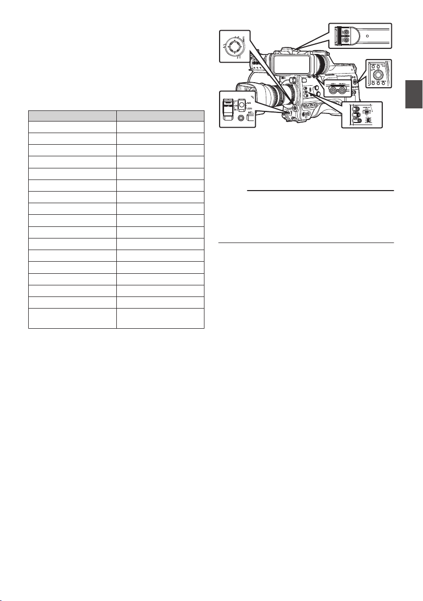
Assignment of Functions
to User Buttons
You can assign functions to the following buttons
and use them as user buttons.
By assigning functions to the buttons, the usability
of the camera recorder can be enhanced.
Perform settings in the menu items corresponding
to each button.
Button Menu Item
[USER0] Switch [USER0]
[USER1] Button [USER1]
[USER2] Switch [USER2]
[USER3] Button [USER3]
[USER4] Button [USER4]
[ONLINE/5] Button [USER5]
[USER6] Button [USER6]
[USER7] Button [USER7]
[AWB/USER8] Switch [USER8]
[J] Button [USER9 ▲]
[K] Button [USER10 ▼]
[H] Button [USER11 ◀]
[I] Button [USER12 ▶]
[SET/USER13] Button [USER13 ●(Front)]
[USER1] Button (VF) [USER1 (VF)]
[USER2] Button (VF) [USER2 (VF)]
[RET] Button on the
Lens
[LENS RET]
.
1
Assign functions to the buttons from the
menu.
Configure each item to the user buttons in
[Camera Function] B [User Switch Set].
(A P111 [User Switch Set Item] )
Memo :
0
Operations of the user buttons are interlocked
with the menu settings.
0
When the menu screen is displayed, these
buttons function as the menu operation buttons.
(A P105 [Basic Operations in Menu Screen] )
Assignment of Functions to User Buttons
45
Preparations
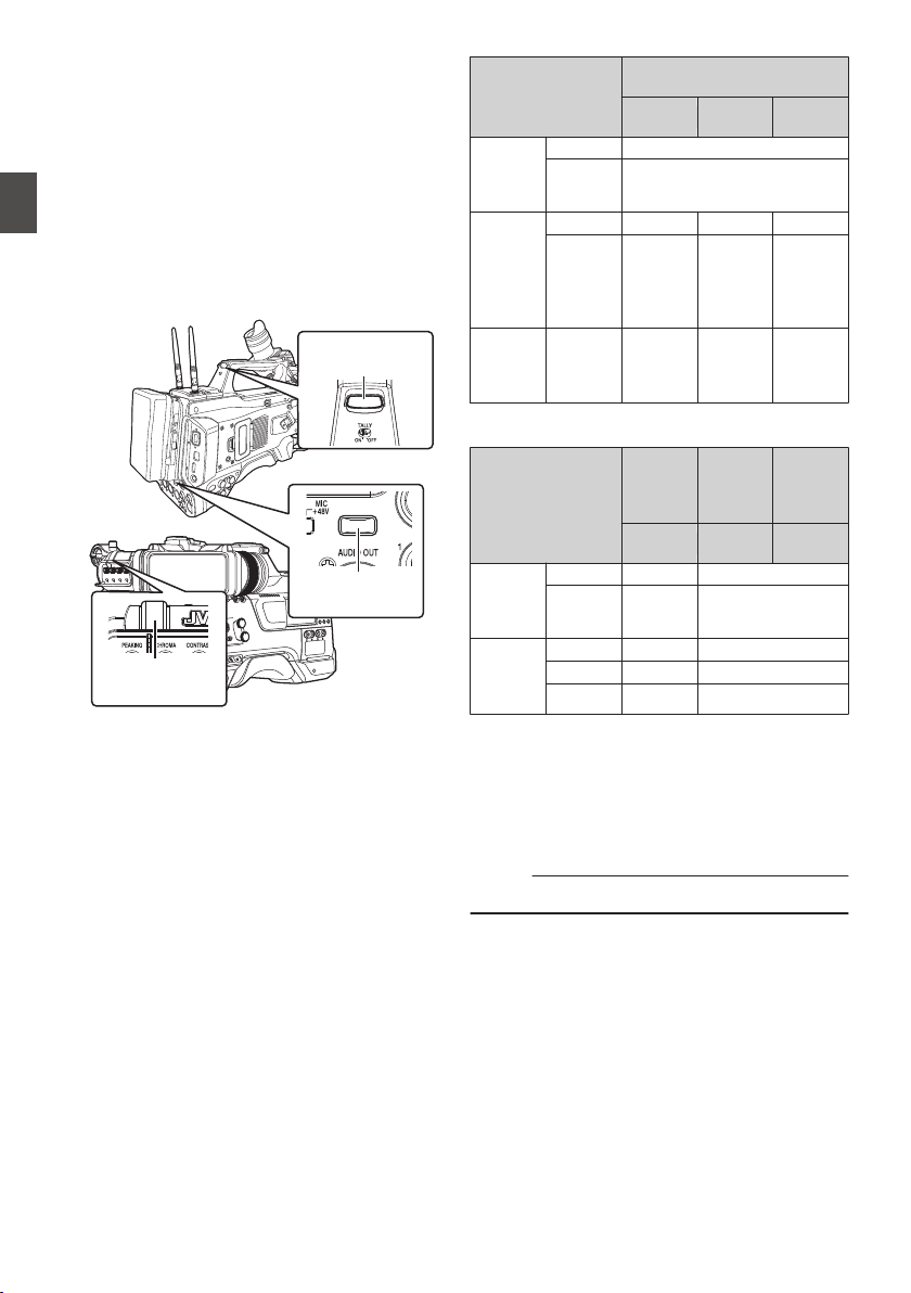
Tally Lamp
This is the indicator lamp for recording and
warning.
The operation changes according to the menu
settings.
The lamp blinks when the battery or remaining
space on the recording media is low. (Camera
mode only)
*
Configure in [System] B [Front Tally]/[Back
Tally].
(A P148 [ Tally System ] )
(A P148 [Front Tally/Back Tally] )
.
*&
Front Tally
Lamp
Back Tally Lamp
(Handle)
Back Tally Lamp
(Rear)
0
When [Tally System] is set to “Internal”
Menu Setting
Front Tally/
Back Tally
Rec
Live
Streaming
Rec/Live
Streaming
Information
on Camera
Recorder
Functions
Warning
J
Alarm
o
Camera
Recorder
Recording
Status
Recording
R
-
R
Special
Recording
in
Progress
*1
R
-
R
Live
Streaming
Status
Live
Streaming
in
Progress
-
R R
0
When [Tally System] is set to “Studio”
[TALLY] Switch
Front
Tally/
Back
Tally
Front
Tally
Back
Tally
OFF
HIGH or
LOW
ON
Information
on Camera
Recorder
Functions
Warning -
J
Alarm
-
o
Input from
Remote
Control
Unit
CALL
-
o
*2
PROGRAM
-
R
PREVIEW
-
R
R
:
Lights up
J
:
Blinks four times in 1 second
o
:
Blinks once in 1 second
*1 Paused state during special recording ([Clip
Continuous]0).
(A P91 [Clip Continuous Rec 0] )
*2 Back tally only
Memo :
0
Blinking takes priority over lighting up.
46
Tally Lamp
Preparations
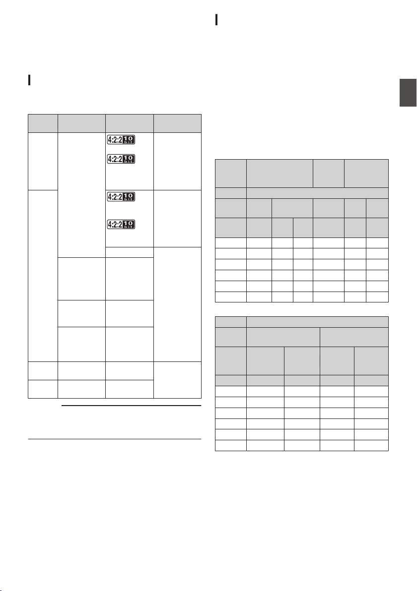
SD Card
This camera recorder saves the recorded images
and audio sound on the SD card (sold separately)
in the card slot.
Usable Cards
Format Setting and Usable SD Card
Combinations
System
Format Bit Rate
Usable SD
Card
High-
Speed
2
QuickTime
(H.264)
70M (XHQ),
50M (XHQ),
50M (XHQ),
35M (UHQ)
UHS-I U3 or
higher
HD
70M (XHQ)
0
,
50M (XHQ),
50M (XHQ)
UHS-I U1 or
higher, or
Class 10 or
higher
35M (UHQ)
UHS-I U1 or
higher, or
Class 6 or
higher
QuickTime
(MPEG2),
MXF
(MPEG2)
0
35M (HQ),
25M (SP)
Exchange
(U model)
0
12M (LP),
8M (LP)
MP4
(H.264)
(E model)
0
12M (LP),
8M (LP)
SD
2
- -
UHS-I U1 or
higher, or
Class 4 or
higher
Web
2
- -
Caution :
0
Using cards other than those from Panasonic,
TOSHIBA or SanDisk may result in recording
failure or data loss.
Estimated Recordable Time of SD Cards
The estimated recordable time is only a guide.
Differences may occur depending on the SD card
in use and the battery condition.
0
The recordable time varies according to the
settings in [System], [WFormat], [WResolution],
[WBit Rate] and [YResolution].
0
The following is the recording time during audio
4ch recording. The recording time is longer for
2ch recording.
(A P151 [ System ] )
(A P151 [ W Format ] )
(A P152 [ W Resolution ] )
(A P153 [ W Bit Rate ] )
(A P153 [ Y Resolution ] )
System
HD,
HD + Web (HD)
SD,
HD + Web
(Web)
HD + Web
(Web)
Format QuickTime (H.264)
Resolution
1920x1080
1920x1080,
1280x720
720x480,
720x576
960x540 480x270
Bit Rate
XHQ
(70M)
XHQ
(50M)
UHQ HQ HQ LP
8GB 12 17 24 80 240 480
16GB 24 35 48 160 480 960
32GB 48 70 96 320 960 1920
64GB* 96 140 192 640 1920 3840
128GB* 192 280 384 1280 3840 7680
256GB* 384 560 768 2560 7680 15360
(Unit: minute)
System HD
Format
QuickTime (MPEG2),
MXF (MPEG2)
Exchange,
MP4 (H.264)
Resolution
1920x1080,
1440x1080,
1280x720
1440x1080 1920x1080 1280x720
Bit Rate HQ SP LP (12M) LP (8M)
8GB 24 32 80 120
16GB 48 64 160 240
32GB 96 130 320 480
64GB* 192 260 640 960
128GB* 384 520 1280 1920
256GB* 768 1040 2560 3840
(Unit: minute)
* SDXC
SD Card
47
Preparations
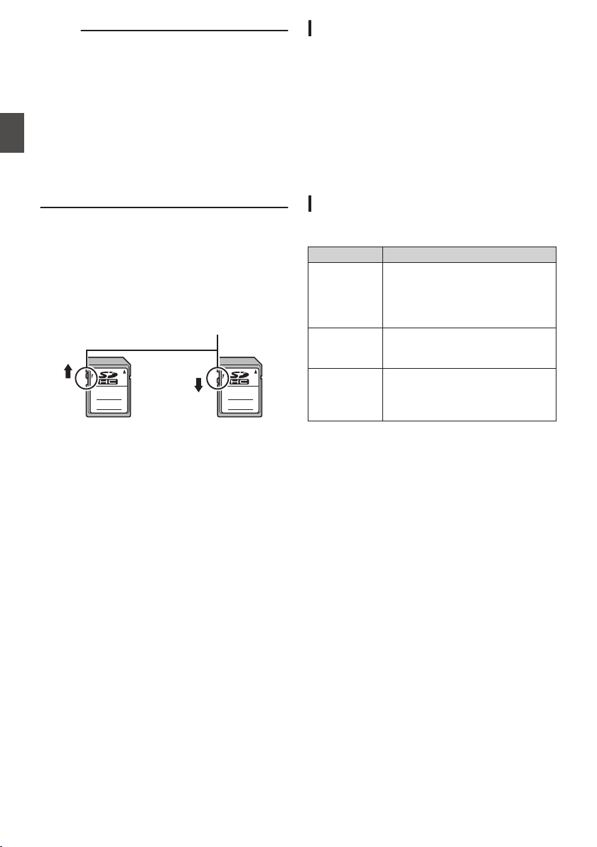
Memo :
0
If the SD card contains files recorded by devices
other than this camera recorder or files that are
saved from a PC, the recordable time may be
shorter or data may not be properly recorded.
0
For each file format, up to 600 clips can be
recorded to one SD card on this camera
recorder. When 600 clips are recorded to one
card, the remaining space is displayed as 0 min
regardless of the estimated recordable time,
and no further recording can be performed.
0
When [System] is configured to “High-Speed”,
the remaining time display for recording to the
SD card will run out faster than usual. 2
Write-Protect Switch on the SD Card
A
Slide the write-protect switch upward to enable
writing or deleting.
B
Slide the write-protect switch downward to
prevent writing or deleting. (Images in the card
are protected.)
.
AB
Write/Delete Enabled Write/Delete Disabled
Write-Protect Switch
Inserting an SD Card
This camera recorder comes with two card slots
(Slot A and B) for video/audio recording and
playback.
1
Press the SD card cover knob to open the
cover.
2
Insert an SD card with the notched corner
pointing up.
The status indicator of the card slot to which the
card was inserted lights up in red.
3
Close the SD card cover.
Card Slot Status Indicator
The following table shows the respective states of
slot A and B.
Lamp Slot Status
Lights up in
red
The inserted SD card is being
accessed. (writing/reading data)
Do not turn off the power of the
camera
recorder or remove the SD
card.
Lights up in
green
On standby. The inserted SD card
can be used for recording or
playback.
Light goes out
0
SD card is not inserted.
0
An unusable card is inserted.
0
An SD card is inserted but a
different slot is selected.
48
SD Card
Preparations

Removing the SD Card
1
Check that the SD card to be removed is not
being accessed (status indicator of the
card slot lights up in red).
2
Press the SD card cover knob to open the
cover.
3
Push the SD card and remove it from the
slot.
4
Close the SD card cover.
Memo :
0
When both slots are inserted with usable SD
cards, the previously selected slot is used.
Caution :
0
Data may be lost if you turn off the power of the
camera recorder or remove the SD card when it
is being accessed. All data recorded on the
card, including the file that is being accessed,
may be corrupted. Be sure to check whether the
status indicator is lit in green or turned off before
you turn off the power or remove the SD card.
0
If you mistakenly remove the card when it is
being accessed, reinsert the card only after the
status indicator goes off.
0
The SD card may not be recognized if you insert
and remove the card within a short time. When
this happens, remove the card and wait for a few
seconds before you reinsert.
Switching the SD cards
When both card slots are inserted with SD cards,
you can use the [SLOT SELECT] button to switch
the card to use.
When the memory on an SD card is full during
recording, data recording automatically switches to
the other card.
Memo :
0
The [SLOT SELECT] button is disabled during
recording or playback. Cards will not be
switched even if you press the button.
SD Card
49
Preparations
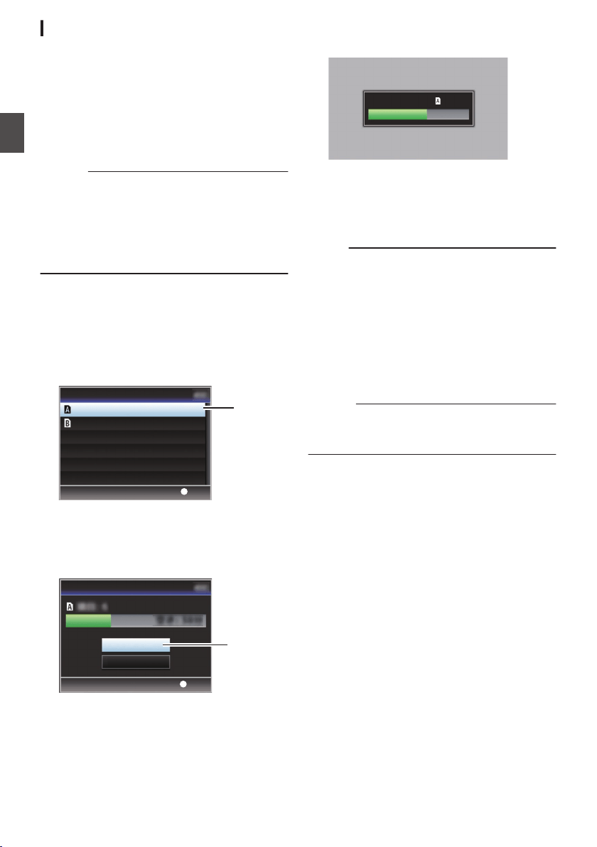
Formatting (Initializing) SD Cards
When the following cards are inserted, [!FORMAT]
appears at the remaining media display area.
Format the card using the camera recorder menu.
0
Unformatted SD cards
0
SD cards formatted under different
specifications
* For details of the menu operation, refer to
“[Basic Operations in Menu Screen]
(A P 105)”.
Caution :
0
Be sure to format the SD card on this camera
recorder. SD cards formatted on a PC and other
peripheral equipment cannot be used on this
camera recorder.
0
[!RESTORE] appears at the remaining media
display area when an SD card that requires
restoring is inserted.
1
Select [System]
B [Media] B [Format
Media].
(A P
148 [ Format Media ] )
2
Select the slot of the SD card to be
formatted and press the [
STATUS/SET]
button (
R).
.
2
Set
Format Media
Format Slot A
Format Slot B
3
The status of the selected SD card appears.
4
Select [Format] and press the
[STATUS/SET] button (
R).
.
4
Set
Cancel
Format
Format Media
5
Formatting starts.
.
Formatting...
6
Formatting is complete.
When formatting is complete, “Complete” appears
and the camera recorder returns to the [Format
Media] screen.
Memo :
0
During formatting, menu operation is
unavailable but you can start recording.
However, this is only available when a
recordable SD card is inserted in the other slot.
0
Formatting cannot be performed in the following
cases.
0
Recording is in progress on the SD card to be
formatted.
0
SD card is not inserted.
0
Write-protect switch of the SD card is set (z
is displayed).
Caution :
0
If you format the SD card, all data recorded on
the card, including video data and setup files,
will be deleted.
50
SD Card
Preparations
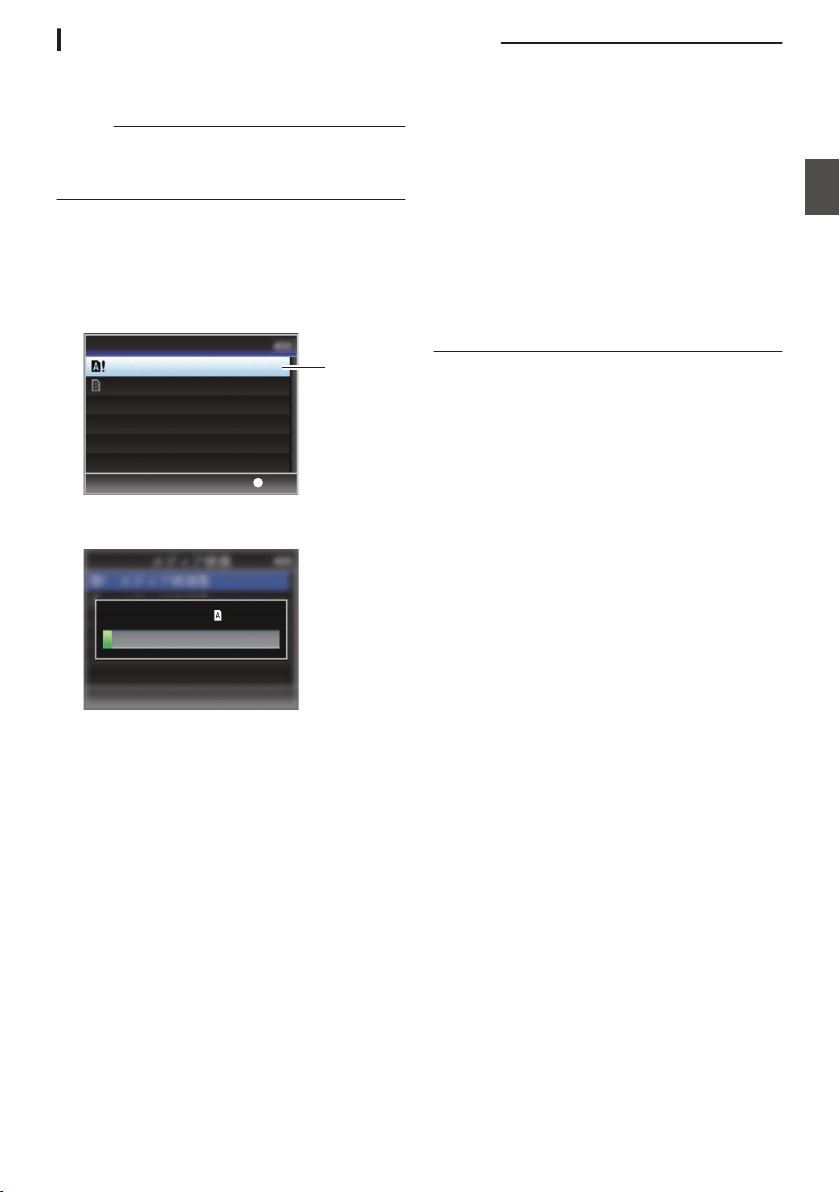
Restoring the SD Card
It is necessary to restore the SD card if an
abnormality occurs to the data in the card due to
some reasons.
Memo :
0
[!RESTORE] appears at the remaining media
display area when an SD card that requires
restoring is inserted.
1
Select [System]
B [Media] B [Restore
Media].
(A P
148 [ Restore Media ] )
2
Select the SD card to be restored and press
the [STATUS/SET] button (
R).
.
2
Set
Restore Media
Restore Slot A
Restore Slot B
3
Restoring starts.
.
Restoring...
4
Restoring is complete.
0
When restoring is complete, “Complete
”
appears
and the camera recorder returns to the
[Restore Media] screen.
0
When no media that requires restoring is
inserted, the camera recorder returns to the
[
Media] menu screen.
Caution :
0
[Restore Media] can only be selected in Camera
mode. However, it cannot be selected while the
camera recorder is recording. Select [Restore
Media] in Camera mode when the camera
recorder is not recording.
0
[Restore
Media] does not restore the SD card to
its original states completely. If restoring fails,
replace or format the SD card. Take note that
formatting erases all the information inside the
SD card.
0
Restoring cannot be performed in the following
cases.
0
Camera recorder is recording in progress.
0
SD card is not inserted.
0
Write-protect switch of the SD card is set (z
is displayed).
SD Card
51
Preparations

Clips Recorded to SD Cards
Folders in the SD Card
The captured image is recorded into different
folders according to the [Format] settings.
0
Other than MXF (MPEG2): [DCIM]
0
MXF (MPEG2): [PRIVATE]
Memo :
0
By formatting (initializing) the SD card from the
[Format Media] menu on the camera recorder,
folders required for recording in the current
[System] settings will be generated.
0
When the [System] settings and [WFormat]/
[YFormat] settings are changed, folders
required for recording in those settings will be
automatically generated.
Caution :
0
When a clip inside the folder is moved or deleted
using the Explorer (Windows) or Finder (Mac),
recording to the SD card may fail if formatting
(initializing) of the card is not performed.
Clip (Recorded Data) and Clip Name
0
When recording is stopped, the images, audio
and accompanying data which are recorded
from start to stop are recorded as one “clip” on
the SD card.
0
An 8-character clip name is automatically
generated for the recorded clip.
(“Clip Name Prefix” + “Clip Number”)
Example: QuickTime
.
ABCG0001
This is set to “xxxG” (“xxx” denotes the last 3
digits of the serial number) by default.
Clip Name Prefix (any four alphanumeric characters)
The Clip Number can be reset in
the menu.*
A number in automatic
ascending order is assigned in
the recording order.
Clip Number
* [Clip Set] B [Reset Clip Number]
(A P156 [ Reset Clip Number ] )
Memo :
0
Before recording starts, you can set any
characters for the clip name prefix by using
[System] B [Record Set] B [Clip Set] B [Clip
Name Prefix].
(A P
156 [ Clip Name Prefix ] )
0
Changes cannot be made after recording.
Recorded Clips
0
The recorded materials may be split into several
files but they can be played back continuously
on the camera recorder.
0
Clips may be recorded across the two SD cards
in card slots A and B depending on the recording
time of the clip.
Caution :
0
A clip recorded across several cards cannot be
played back continuously. Continuous playback
is only possible when the recording is made on
one card.
52
SD Card
Preparations

Operation Lock Feature
You can use this feature to prevent erroneous
camera operation.
.
1
While in the Camera mode (when the
display screen appears), press and hold
the [CANCEL/RESET] button for 5 seconds
or longer.
0
The operation lock turns on, and an operation
lock icon (r) appears on the display
screen.
0
Press the [CANCEL/RESET] button again for
5 seconds or longer to turn off the operation
lock.
Memo :
0
The operation lock feature is only valid in the
Camera mode.
(A P20 [Operation Modes] )
0
The power turns off and the operation lock is
disengaged.
0
The following remote operations are possible
even when the operation lock feature is turned
on (“On”).
0
Operation from the remote control unit that is
connected to the [REMOTE] terminal.
0
Remote operation of the camera through
access via a browser on devices such as a
smartphone, tablet terminal, or PC.
Operation lock does not apply to the following
buttons and switches.
0
[POWER ON/OFF] switch
0
[ND FILTER] switch
0
[MONI SELECT] switch
0
[CH SELECT] switch
0
[AUDIO INPUT CH1/2/3/4] recording level
adjustment knob
0
[AUDIO SELECT CH1/2/3/4]-[
MANUAL/
AUTO] selection switch
0
[AUDIO SELECT CH1/2/3/4
]-[FRONT/REAR/
WIRELESS] selection switch
0
[TC PRESET
] button
0
[TC GEN] time code generator switch
0
[MONITOR] volume adjustment knob
0
[ALARM] volume adjustment knob
0
[REC] button
0
User button assigned with the [Rec
] function
0
All switches on the lens
0
While the viewfinder is connected
0
[PEAKING][BRIGHT][CONTRAST]
[CHROMA] Knob
0
[MIRROR]
[TALLY] Switch
Operation Lock Feature
53
Preparations
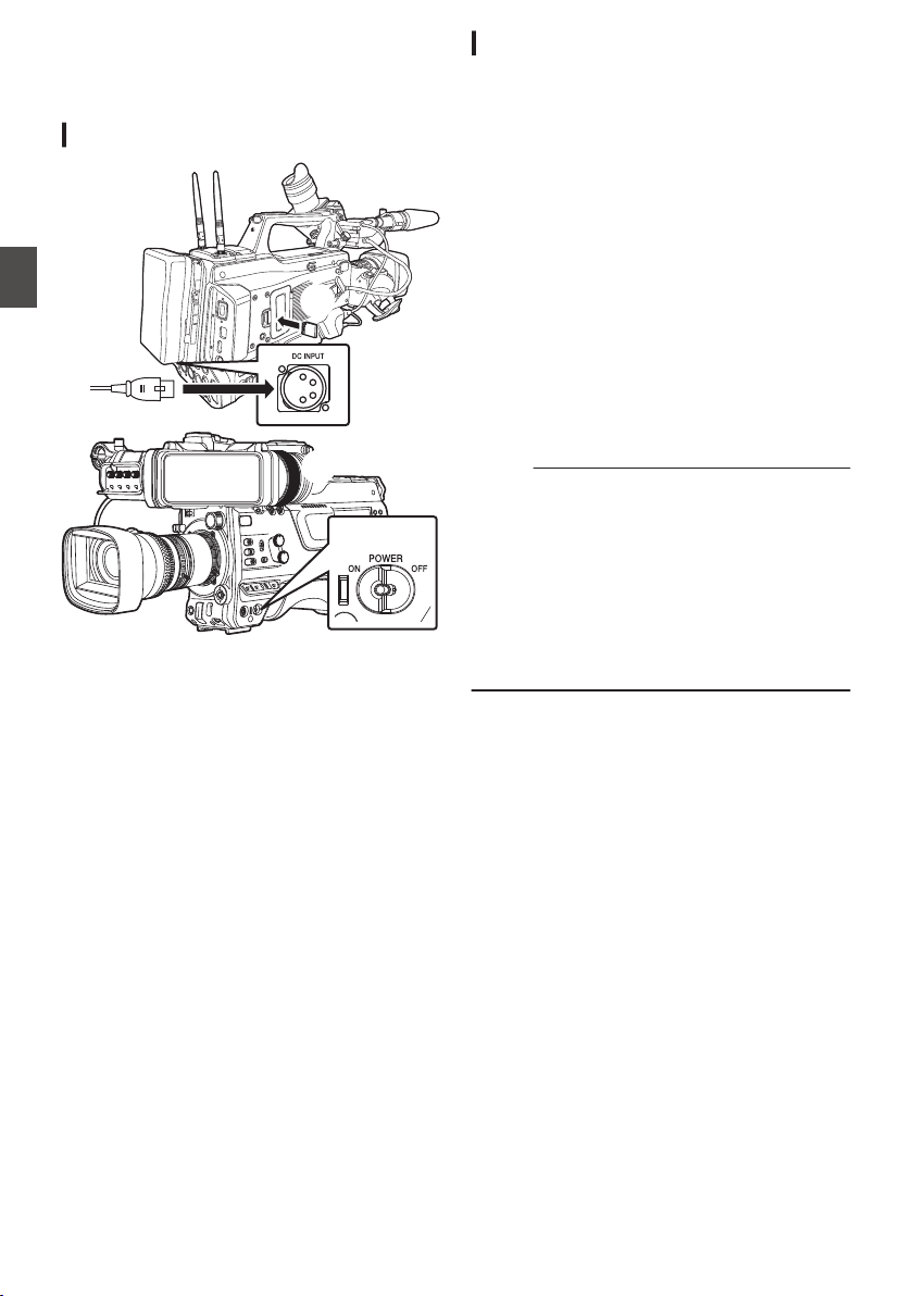
Basic Shooting
Procedures
Preparations
.
2
4
1
3
1
Supply battery or AC adapter power to the
camera recorder.
(A P33 [Power Supply] )
2
Insert the recording media
(A P47 [SD Card] )
3
Turn on the power of the camera recorder.
Setting the [POWER ON/OFF] switch to “ON”
starts up the camera recorder in the Camera
mode to enable shooting.
4
Adjust the angle of the viewfinder.
(A P42 [Adjusting the LCD Monitor and
Viewfinder] )
5
Set [System], [Format], [Resolution],
[Frame Rate], [Bit Rate] and [Audio] in
[System]
B [Record Set] B [Record
Format].
0
You can select the definition of the recorded
videos, file format for recording/playback,
and the video recording format on this
camera recorder.
0
Press the [MENU/THUMB] button to display
the menu screen on the LCD monitor and
viewfinder.
Shooting
1
Configure the video and audio input
settings.
You have to configure video settings such as
brightness adjustment (iris, gain, shutter) and
white balance adjustment in order to start
shooting. You also have to adjust the audio
input settings and audio recording level for
audio recording.
0
Adjusting the Brightness
0
Adjusting the White Balance
0
Adjusting Audio Input Settings and
Recording Level
2
Press the [REC] button to start recording to
the recording media
The tally lamp lights up in red during recording.
0
Zoom Operation
(A P57 [Zoom Operation] )
0
Adjusting the Focus
(A P58 [Focus Operation] )
Memo :
0
If both the slots are loaded with recordable cards
in the factory default, pressing the [REC] button
starts recording only to the media in the selected
slot.
When [System] B [Record Set] B [Slot Mode] is
set to “Dual”, recording can be performed
simultaneously to the cards in both the slots.
(A P86
[Dual Rec] )
0
The tally lamp can be turned off by setting the
[TALLY] switch to “OFF”.
3
Check the most recently captured images.
0
Press the user button that is assigned with
the Clip Review function. Doing so activates
the function and plays back the most recently
captured images on the LCD monitor and
viewfinder screen.
0
After playback, the camera recorder returns
to standby mode (STBY).
(A P84 [Viewing Recorded Videos
Immediately (Clip Review)] )
54
Basic Shooting Procedures
Shooting

Selecting System
Definition, File Format and
Video Format
You can select the definition of the recorded
videos, file format for recording/playback, and the
video recording format on this camera recorder.
Setting the Record Format Menu
1
Set [System], [Format], [Resolution],
[Frame Rate] and [Bit Rate] in [System]
B
[Record Set]
B [Record Format].
2
Set each of the items.
A
[Selecting a System Definition] (A P 55)
B
[Selecting a File Format] (A P 55)
C
[Selecting a Video Format] (A P 56)
D
[Selecting the Aspect Ratio of SD Videos
2] (A P 57)
3
After setting is complete for all items, press
the
[USER1] button.
0
The recording format is switched.
0
A “Please Wait...” message appears on the
screen during switching.
Selecting a System Definition
The following definitions are available for selection.
0
HD:
Records in HD (High Definition) resolution
(1920x1080 or 1280x720)
0
SD 2:
Records in SD (Standard Definition) resolution
(720x480 or 720x576)
0
Web2:
Records in resolution (960x540, 720x480,
720x576, or 480x270) suitable for web
distribution
0
High-Speed2:
Records in HD resolution (1920×1080)
You can select a definition for the recorded images
from the following items under
[
System].
0
HD:
Records in HD quality for both slots A and B.
0
SD 2:
Records in SD quality for both slots A and B.
0
HD(SDI In):
Records the HD SDI video of the device
connected to the [HD/SD SDI IN] terminal in
“HD” to both slot A and slot B.
0
SD(SDI In)2:
Records the SD SDI video of the device
connected to the [HD/SD SDI IN] terminal in
“SD” to both slot A and slot B.
0
HD+Web2:
Records
in HD quality for slot A, and Web quality
for slot B.
(A P86 [Recording Simultaneously at Two
Different Definitions 2] )
0
High-Speed2:
Records in HD quality for both slots A and B.
Caution :
0
When [System] B [Record Set] B [Record
Format] B [System] is configured to “High-
Speed”2, network cannot be used via
wireless LAN u v or the [HOST] terminal
(USB). Configure as follows in this case.
0
Set
[Network] B [Connection Setup] B [USB/
Int. WLAN] to “Off”. u v
0
Unplug the USB network adapter
Note that camera operation will come to an
emergency
stop and the power will turn off if the
above steps are not performed.
File data may be damaged if this happens while
recording is in progress.
Selecting a File Format
Select a file format in [WFormat]/[YFormat].
The following file formats are available for
selection.
0
QuickTime (MPEG2):
QuickTime file format (.MOV)
0
MXF (MPEG2)0:
MXF (material exchange format)
0
QuickTime (H.264):
QuickTime file format (.MOV)
0
Exchange0: (U model only)
Sports Video Interop Group format (.MP4)
0
MP4 (H.264)0: (E model only)
MP4 file format
Memo :
0
Exchange (U model) and MP4 (E model) are
selectable only when [System] is configured to
“HD”.
0
When
Exchange
(U model) or MP4 (E model) is
selected, backup recording and clip cutter
function cannot be used.
Selecting System Definition, File Format and Video Format
55
Shooting

Selecting a Video Format
0
The selectable [Frame Rate]/[Bit Rate] changes
according to the settings of [System]/[Format]/
[Resolution].
List of Formats
The following is a list of file formats and video
formats that can be selected on this camera
recorder.
o
When [
System] is configured to “HD”, “HD
+Web”, 2 or “HD(SDI In)”, the options for
slot A are:
Record Format
W
Format
W
Resolution
W
Frame
Rate
W
Bit Rate
W
Audio
QuickTime
(MPEG2),
MXF
(MPEG2)
1920x1080 60i, 50i,
30p*,
25p*
35M (HQ)
4CH 16 bit/
2CH 16 bit
1440x1080 60i, 50i 35M (HQ),
25M (SP)
1280x720 60p, 50p 35M (HQ)
QuickTime
(H.264)
1920x1080 60p, 50p
70M (XHQ),
50M (XHQ)
4CH 24 bit/
2CH 24 bit
50M (XHQ) 4CH 16 bit/
2CH 16 bit
60i, 50i,
30p*,
25p*,
24p*
50M (XHQ)
4CH 24 bit/
2CH 24 bit
50M (XHQ),
35M (UHQ)
4CH 16 bit/
2CH 16 bit
1280x720 60p, 50p
50M (XHQ)
4CH 24 bit/
2CH 24 bit
35M (UHQ) 4CH 16 bit/
2CH 16 bit
Exchange
(U model)
1920x1080 60p 12M (LP) 2CH
1280x720 8M (LP)
MP4
(H.264)
(E model)
1920x1080
50p 12M (LP) 2CH
1280x720 8M (LP)
* Not selectable when configuring “HD(SDI In)”.
Memo :
0
When [System] is set to “HD” or “HD(SDI In)”,
each item for slot B is fixed at the same setting
as slot A.
0
When “HD+Web”[System] is set to 2,
[Format] is fixed at “QuickTime(H.264)”.
0
When
[WFormat] is configured to “Exchange” or
“MP4(H.264)”, selection is possible only when
[System] is configured to “HD” or “HD(SDI In)”.
0
The following functions cannot be used when
HD+Web is selected.
View Remote, Live Streaming, Return over IP
o
When [System] is set to
“High-Speed”2
Record Format
W
Format
W
Resolution
W
Frame
Rate
W
Bit Rate
W
Audio
QuickTime
(H.264)
1920x1080 120/60p,
100/50p
70M (XHQ),
50M (XHQ)
2CH 24 bit
50M (XHQ) 2CH 16 bit
120/30p,
100/25p,
120/24p
50M (XHQ)
2CH 24 bit
50M (XHQ),
35M (UHQ)
2CH 16 bit
Caution :
0
When [System] B [Record Set] B [Record
Format] B [System] is configured to “High-
Speed”2, network cannot be used via
wireless LAN u v or the [HOST] terminal
(USB). Configure as follows in this case.
0
Set
[Network] B [Connection Setup] B [USB/
Int. WLAN] to “Off”. u v
0
Unplug the USB network adapter
Note that camera operation will come to an
emergency
stop and the power will turn off if the
above steps are not performed.
File data may be damaged if this happens while
recording is in progress.
Memo :
0
The [Rec Mode] is fixed at “Normal”.
0
The following functions cannot be used when
High-Speed is selected.
View Remote, Live Streaming, Return over IP,
Upload of recorded clip, time stamp recording
and Pixel Mapping
0
The settings for slot B are fixed at the same as
slot A.
0
When the [
TC GEN]
] selection switch is set to
“F-RUN”, the time code will be recorded in “R-
RUN”.
0
[TC/UB...
] B [TC Mode] is fixed at “SW Set”.
0
It is not possible to set a shutter speed that is
slower than the frame rate.
(Example: When 120/60p is selected, 1/120 to
1/9873 can be set.)
0
The sensitivity of high speed shooting is lower
than normal shooting. In order to capture more
beautiful images, it is recommended to perform
shooting in a lighted environment.
0
The remaining space on the media (recordable
time to the recording media) runs out faster than
usual.
(Example: For 120/60p, as the recording speed
is twice as fast as usual, the remaining space on
the media is reduced by approximately double
the speed.)
56
Selecting System Definition, File Format and Video Format
Shooting
o
When [System] is set to “SD” or “SD(SDI In)”:
2
Record Format
W
Format
W
Resolution
W
Frame
Rate
W
Bit Rate
W
Audio
QuickTime
(H.264)
720x480 60i
(U model)
8M (HQ) 4CH 16 bit/
2CH 16 bit
720x576 50i
(E model)
Memo :
0
Each item for slot B is fixed at the same setting
as slot A.
o
When [System] is set to “HD+Web”, the options
for slot B are 2:
Record Format
Y
Format
Y
Resolution
Y
Frame
Rate
Y
Bit Rate
Y
Audio
QuickTime
(H.264)
960x540 30p, 25p,
24p
3M (HQ) 4CH/
2CH
720x480 60i 8M (HQ)
4CH 16 bit/
2CH 16 bit
720x576 50i 8M (HQ)
480x270 30p, 25p,
24p
1.2M (LP) 4CH/
2CH
Memo :
0
The following functions cannot be used when
HD+Web is selected.
View Remote, Live Streaming, Return over IP
Selecting the Aspect Ratio of SD Videos
2
For setting the aspect ratio of the recorded image
when [System] is set to “SD” or “SD(SDI In)”.
You can select “16:9” or “4:3”.
Memo :
0
For conditions other than those above, this item
is fixed at “16:9”.
Zoom Operation
Adjusts the angle of view.
Zooming can be operated using the following.
0
Zoom ring/zoom lever on the commercially
available lens
0
User buttons assigned with “Zoom Tele” and
“Zoom Wide”
During the zoom operation, the zoom bar or
number
will appear on the upper right corner of the
screen.
(A P164 [Zoom Display] )
Caution :
0
Depending on the zoom speed, the zoom drive
noise of the power zoom may be recorded.
Using Zoom Ring/Zoom Lever on
Commercially Available Lens
You can adjust the preferred angle of view by
turning the zoom ring or operating the zoom lever.
Memo :
0
For details on the lens, please refer to the
“INSTRUCTIONS” of the lens used.
Using User Buttons Assigned with
“Zoom Tele” and
“Zoom Wide”
1
Assign “Zoom Tele” and “Zoom Wide” to
the user buttons.
(A P45 [Assignment of Functions to User
Buttons] )
(A P111 [User Switch Set Item] )
0
Configure the zoom speed of the user
buttons in [Camera Function] B [User Switch
Set] B [Zoom Speed].
Increasing the value increases the zoom
speed.
2
Press the user button assigned with “Zoom
Tele”/“Zoom Wide” to zoom.
0
The zoom operation is performed in the
speed that has been set.
Memo :
0
This function may not work depending on the
lens attached.
Selecting System Definition, File Format and Video Format
57
Shooting
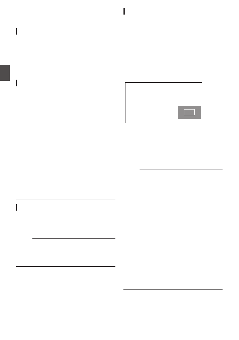
Focus Operation
Adjusting the Focus
1
Turn the focus ring to adjust the focus.
Memo :
0
Using the Focus Assist or Expanded Focus
function makes it easier to focus.
(A P58 [Focus Assist Function] )
(A P58 [Expanded Focus Function] )
Focus Assist Function
0
When the user button assigned with “Focus
Assist” is pressed, the focused area is displayed
in color. This enables easy and accurate
focusing.
0
Select
the color (blue, red or green) in the menu.
Memo :
0
When [LCD/VF
] B [Shooting Assist] B [Focus
Assist] B [Type] is set to “ACCU-Focus”, the
depth of field becomes shallower to enable
easier focusing.
(A P126
[ Focus Assist ] )
0
The “ACCU-Focus” function switches
automatically to “Off” after about 10 seconds.
0
Select
the display color in [LCD/VF] B [Shooting
Assist] B [Focus Assist]B[Color].
(A
P126 [ Color ] )
0
If you use the zebra function and the Focus
Assist function at the same time, it may be
difficult to see the effect of the Focus Assist. In
this case, turn off the zebra function.
Focus Assist + Function
0
You can operate the Focus Assist and
Expanded Focus functions simultaneously by
pressing the user button assigned with “Focus
Assist +”.
Memo :
0
“Expanded Focus
” is displayed during the
“Focus Assist +” operation regardless of the
setting in [Camera Function] B [User Switch
Set] B [Expanded Focus].
Expanded Focus Function
You can magnify the preferred area by pressing the
user button assigned with “Expanded Focus”;
doing so enables precise focus to be established
easily.
1
When the user button that is assigned with
“Expanded Focus” is pressed
0
The center area of the screen is enlarged for
the first time.
0
For subsequent operation of the button, the
area at which the operation was last
performed will be enlarged.
.
2
Use the cross-shaped button (
JKH I) to
magnify the preferred area.
0
The portion that is being magnified is
displayed at the lower right corner of the
screen.
3
Press the [CANCEL/RESET] button to
cancel the setting.
Memo :
0
The display of the enlarged screen is dot by dot
equivalent.
0
To set the operation when the button is pressed,
go to [Camera Function] B [User Switch Set] B
[Expanded Focus].
(A P
114 [ Expanded Focus ] )
0
Pressing and holding the Set button (R) resets
the position of magnification.
0
This function can be used together with the
Focus Assist function.
0
Magnifying an image does not alter the size of
the recorded image.
0
If the “Expanded Focus” function is assigned to
the cross-shaped button, the cross-shaped
button cannot be used as user button while the
area is being magnified.
0
This function is unavailable when [System] B
[Record Set] B [Record Format] B [System] is
set to “SD”.
0
When the display screen is turned off, the
magnified
area at the bottom right of the screen
will not be displayed.
58
Focus Operation
Shooting
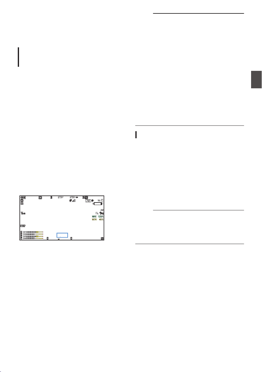
Adjusting the Brightness
Adjust the brightness using Iris, Gain, Shutter
speed and ND filter according to the brightness of
the object.
Adjusting
the Brightness Automatically:
Automatic Brightness Adjustment (AE)
Mode
Iris, Gain, Shutter speed and ND filter are
automatically adjusted according to the brightness
of the object to maintain optimum brightness.
To set only the Gain, Iris and Shutter to Auto mode,
set the Full Auto mode to off before setting each
item to the automatic adjustment mode using the
user button assigned with “Full Auto”.
1
Set Gain, Iris and Shutter to Auto mode.
0
[Adjusting the Iris] (A P 60)
0
[Setting the Gain] (A P 61)
0
[Setting the Electronic Shutter] (A P 62)
2
Set the target level (brighter/darker) to
maintain optimum brightness during
automatic adjustment.
0
Press the user button assigned with “AE
Level” and when the “AE±” indication turns
white operate the cross-shaped button (JK)
to set the target level.
0
This can be configured in [Camera
Function
] B [AE Level].
.
100min
50min
282min
1
/60
F2.8
AE
±0
ND1
/64
12 :34 :56
ISO
102400
00: 00:00.00
1080 /30p
SDI IN
ITU709
COMPRESS
5 . 6 f t
B 5600
K
Memo :
0
Using the user button assigned with “Full Auto”
to enter the Full Auto mode also activates the
automatic brightness adjustment (AE) mode. In
this case, the White Balance also enters into
Auto mode forcibly.
0
The convergence speed of the automatic
adjustment for automatic brightness adjustment
(AE) can be set in the menu.
(A P109 [ AE Speed ] )
0
If one or more of the items (Gain, Iris and
Shutter) have been set to Auto mode, the value
of the corresponding items when the user button
that is assigned “AE Lock” is pressed can be
fixed.
(A P113 [ AE Lock ] )
0
If one or more of the items (Gain, Iris and
Shutter) have been set to Auto mode, the
automatic brightness adjustment (AE) mode is
enabled.
Adjusting the Brightness Manually
Use the user button assigned with “Full Auto” to set
Full Auto mode to off, some or all of the items (Iris,
Gain and Shutter Speed) can be manually
adjusted.
1
Set Full Auto mode to off using the user
button assigned with “Full Auto”.
2
Adjust the Iris, Gain and Shutter speed.
0
[Adjusting the Iris] (A P 60)
0
[Setting the Gain] (A P 61)
0
[Setting the Electronic Shutter] (A P 62)
Memo :
0
The brightness cannot be manually adjusted in
the Full Auto mode.
0
If Iris, Gain and Shutter Speed are manually
adjusted, the [AE Level] setting is temporarily
disabled.
Adjusting the Brightness
59
Shooting
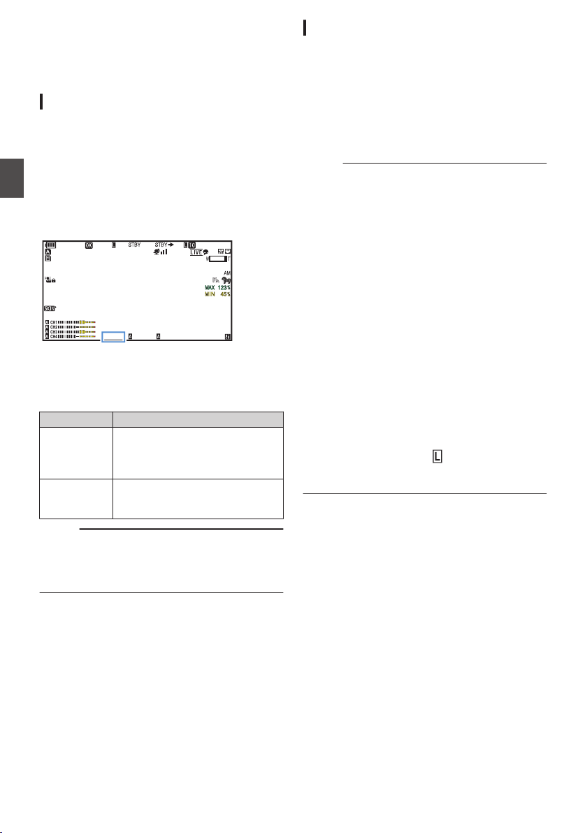
Adjusting the Iris
Adjust the aperture of the lens iris according to the
brightness of the subject.
Manual Iris (Manual Adjustment) Mode
The aperture value (F-number) of the lens can be
set manually.
1
Set Full Auto mode to off using the user
button assigned with “Full Auto”.
2
Set to Manual Iris mode using the [IRIS
A/M] switch on the lens.
The lens aperture value (F-number) is
displayed.
.
100min
50min
282min
1
/60
F2.8
AE
±0
ND1
/64
12 :34 :56
ISO
102400
00: 00:00.00
1080 /30p
SDI IN
ITU709
COMPRESS
5 . 6 f t
B 5600
K
3
Turn the iris ring on the lens to adjust the
iris manually.
The open F-number of the aperture varies
according to the zoom position.
F-number Description
Decrease The subject appears brighter.
The focused range becomes
sharper, while the background is
blurred to produce a soft image.
Increase The subject appears darker.
Background of image becomes
focused as well.
Memo :
0
Even while in the Manual Iris mode, pressing
and holding the [IRIS] button on the lens
switches the camera recorder to the Push Auto
Iris mode.
Push Auto Iris
When the camera recorder is in the Manual Iris
mode, press and hold the [IRIS] button on the lens
to change to the Auto Iris mode temporarily. The
iris will be automatically adjusted according to the
brightness of the subject.
Auto Iris (Automatic Adjustment) Mode
1
Set Full Auto mode to off using the user
button assigned with “Full Auto”.
2
Set to Auto Iris mode using the [IRIS A/M]
switch on the lens.
The iris is automatically adjusted according to
the brightness of the object.
A v icon appears on the left side of the lens
aperture value (F-number) in the Auto Iris mode.
Memo :
0
Use the user button assigned with “Full Auto” to
enter the Full Auto mode also activates the Auto
Iris mode. In this case, the Gain, Shutter and
White Balance also enter into Auto mode
forcibly.
The iris operation during Full Auto mode can be
configured in [Camera Function] B [Full Auto] B
[Iris Control].
0
The iris open/close limit can be set in
[Camera
Function] B [Auto Iris Limit (OPEN)]/[Auto Iris
Limit (CLOSE)] during Auto Iris.
(A
P110 [ Auto Iris Limit (OPEN) ] )
(A P110 [ Auto Iris Limit (CLOSE) ] )
0
You can press the user button assigned with “AE
Level” and use the cross-shaped button (JK) to
configured the target level (brighter/darker) of
the auto iris in [Camera Function] B [AE Level].
0
The convergence speed of the auto iris can be
set in the menu.
(A P109
[ AE Speed ] )
0
While in the Auto Iris mode, and [AE Lock] is set
to “AE” or “AE/FAW”, a
icon appears on the
left side of the lens aperture value (F-number)
during lock operation.
60
Adjusting the Iris
Shooting
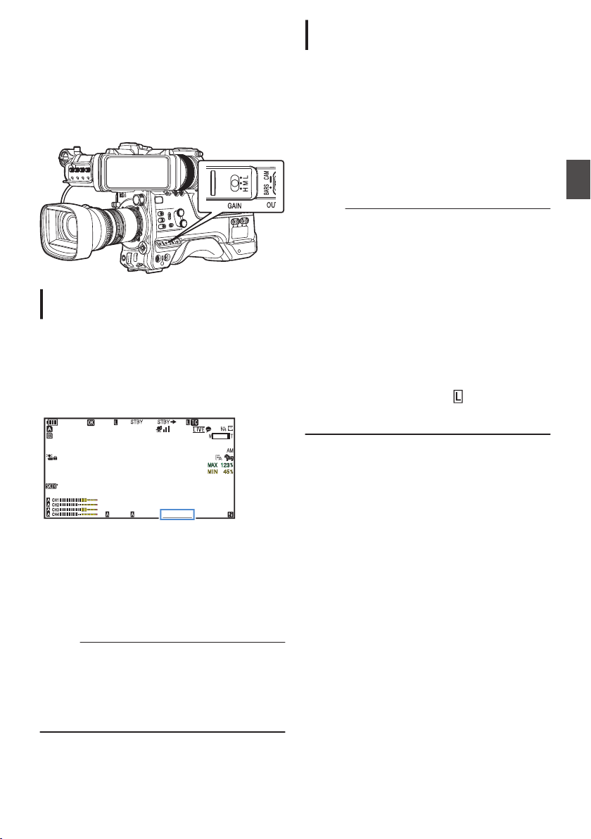
Setting the Gain
This function electrically boosts the light sensitivity
when there is insufficient illumination on the object.
You can set the gain of the video amplifier
according to the brightness of the object. Select the
setting mode according to your shooting
conditions.
.
Manual Gain Mode (Manual Gain
Switching)
1
Set Full Auto mode to off using the user
button assigned with “Full Auto”.
0
Select the gain level of the video amplifier
using the [GAIN L/M/H] selection switch on
the camera recorder.
0
The gain level appears on the screen.
.
100min
50min
282min
1
/60
F2.8
AE
±0
ND1
/64
12 :34 :56
ISO
102400
00: 00:00.00
1080 /30p
SDI IN
ITU709
COMPRESS
5 . 6 f t
B 5600
K
0
The default positions of the switch are as
follows.
[L] : 0 dB
[M] : 6dB
[H] : 12dB
2
Select [GAIN
L/M/H] that is not set to “AGC”
to switch to the Manual Gain mode.
Memo :
0
You can change the gain value of each position
in the menu. Increasing the sensitivity causes
the screen to appear grainier.
0
The camera recorder switches to the Auto Gain
mode when the gain value is set to “AGC”.
(A P110 [GAIN L, GAIN M, GAIN H] )
Automatic Gain Mode (Automatic Gain
Adjustment)
1
Set Full Auto mode to off using the user
button assigned with
“Full Auto”.
2
Set [Camera Function]
B [GAIN L]/[GAIN
M]/[GAIN H] to “AGC”.
(A P
110 [GAIN L, GAIN M, GAIN H] )
If an item specified with “AGC” is selected using
the [GAIN L/M/H] gain switch, the Auto Gain
Adjustment mode is enabled and the gain of the
video amplifier is automatically set according to
the brightness of the subject.
Memo :
0
Use the user button assigned with “Full Auto” to
enter the Full Auto mode also activates the Auto
Gain mode. In this case, the Iris, Shutter and
White Balance also enter into Auto mode
forcibly.
0
The gain operation during Full Auto mode can
be configured in [Camera Function] B [Full
Auto] B [Gain].
0
The upper limit of the gain setting value during
AGC operation can be set in
[Camera
Function] B [AGC Limit].
(A P110
[ AGC Limit ] )
0
While in the Auto Gain mode, and [AE Lock] is
set to “AE” or “AE/FAW”, a
icon appears on
the left side of the gain value during lock
operation.
Setting the Gain
61
Shooting
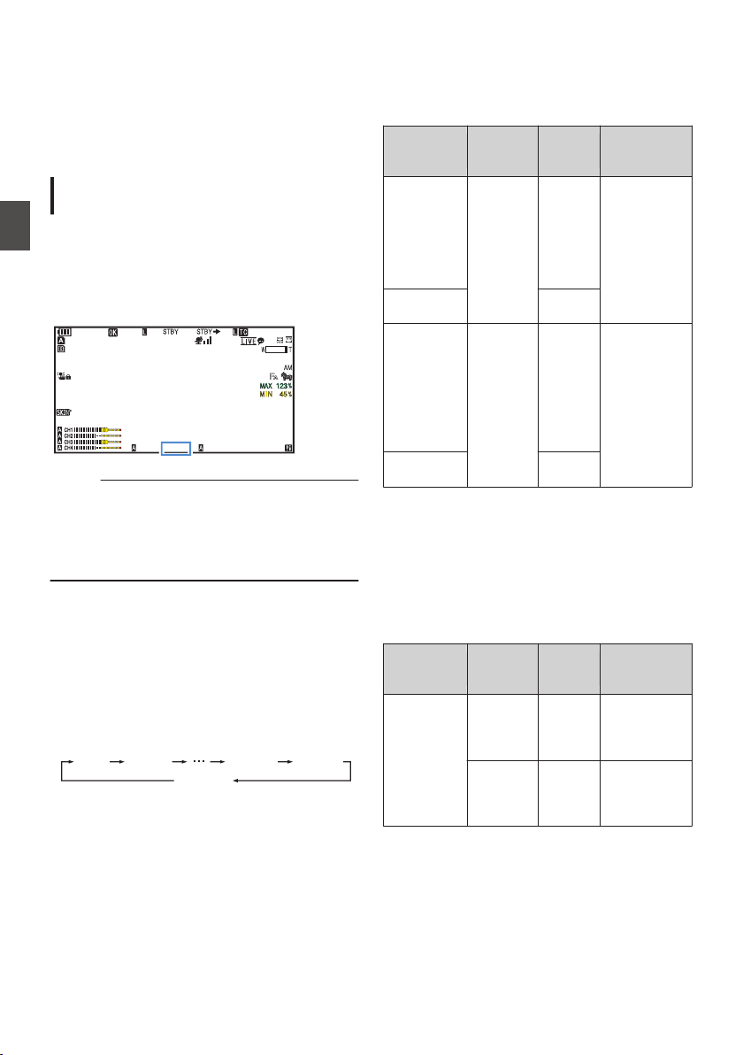
Setting the Electronic
Shutter
You can change the shutter speed (time for each
shooting frame) using the electronic shutter
function. Electronic shutter can be adjusted
manually or automatically.
Manual Shutter Mode (Manual Shutter
Switching)
1
Set Full Auto mode to off using the user
button assigned with “Full Auto”.
2
Set [Camera Function]
B [Shutter] to
“Slow” or “Step/Variable”.
0
The shutter speed appears on the screen.
.
100min
50min
282min
1
/60
F2.8
AE
±0
ND1
/64
12 :34 :56
ISO
102400
00: 00:00.00
1080 /30p
SDI IN
ITU709
COMPRESS
5 . 6 f t
B 5600
K
Memo :
0
To display Shutter in angle (DEG), set [WFrame
Rate] to “25p” and set [LCD/VF] B [Display
Type] B [Shutter] to “DEG”.
(A P152
[ W Frame Rate ] )
(A P109 [ Shutter ] )
Switching Shutter Speed
o
Manual shutter mode (step/variable)
Press down the [SHUTTER] switch toward the
“SEL” end. When the shutter speed indication turns
white, press down the [SHUTTER] switch
repeatedly to change the setting.
Example:
.
1/60 1/100 1/2000
1/60.00
1/1000
Variable
Step
After the shutter speed indication turns white, the
setting value can be changed using the cross-
shaped button (JK).
You can use the cross-shaped button I to switch
to variable mode and the cross-shaped button H to
switch to step mode.
Shutter
Mode
Frame
Rate
Setting
Value
Setting Value
(Shutter
OFF)
Step
60p, 60i,
30p
1/60,
1/100,
1/120,
1/250,
1/500,
1/1000,
1/2000
1/60
Variable 1/30.00 -
1/9873
Step
50p, 50i,
25p
1/50,
1/60,
1/100,
1/120,
1/250,
1/500,
1/1000,
1/2000
1/50
Variable 1/25.00 -
1/9873
o
Manual shutter mode (low speed)
Press down the [SHUTTER] switch toward the
“SEL”
end. When the shutter speed indication turns
white, press down the [SHUTTER] switch
repeatedly to change the setting.
After the shutter speed indication turns white, the
setting value can also be changed using the cross-
shaped button (JK).
Shutter
Mode
Frame
Rate
Setting
Value
Setting Value
(Shutter
OFF)
Slow 60p, 60i,
30p
1/30,
1/15,
1/7.5,
1/3.75
1/60
50p, 50i,
25p
1/25,
1/12.5,
1/6.25,
1/3.125
1/50
62
Setting the Electronic Shutter
Shooting
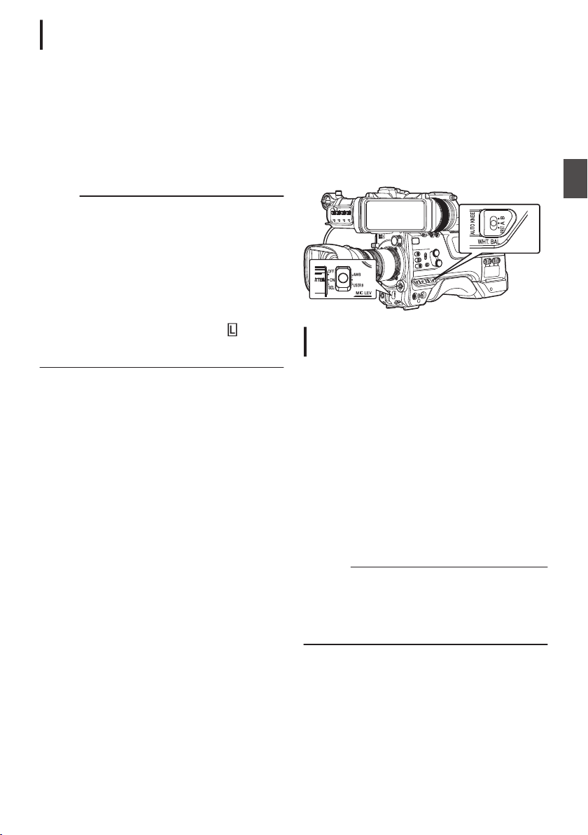
Automatic Shutter Mode (Automatic
Shutter Adjustment)
1
Set Full Auto mode to off using the user
button assigned with
“Full Auto”.
2
Set [Camera Function]
B [Shutter] to “EEI”.
0
Automatic Shutter mode adjusts the shutter
speed automatically according to the
brightness of the object.
3
Set the controllable range for the Automatic
Shutter in [Camera Function]
B [EEI Limit].
(A P110 [ EEI Limit ] )
Memo :
0
Use the user button assigned with “Full Auto” to
enter the Full Auto mode also activates the
Automatic Shutter mode. In this case, the Iris,
Gain and White Balance also enter into Auto
mode forcibly.
0
The shutter operation during Full Auto mode can
be configured in [Camera Function] B [Full
Auto] B [Shutter].
0
While in the Automatic Shutter mode, and
[AE
Lock] is set to “AE” or “AE/FAW”, a
icon
appears on the left side of the shutter speed
during lock operation.
Adjusting the White
Balance
Adjust the white balance according to the color
temperature of the lighting. You can select the
adjustment mode according to the shooting
conditions.
As the color of the light (color temperature) varies
according to the light source, it is necessary to
readjust the white balance when the main light
source illuminating the subject changes.
.
Automatic White Balance Mode (FAW:
Fulltime Auto White balance)
1
Set Full Auto mode to off using the user
button assigned with “Full Auto”.
2
Assign “FAW” (Full Auto White Balance) to
one of the three [WHT.BAL] switches.
0
You can set the Full Auto White Balance
feature to either “A”, “B”, or “PRST
” in
[Camera Function] B [FAW].
(A P
110 [ FAW ] )
0
If the position assigned with “FAW” is
selected using the [WHT BAL B/A/PRST]
switch, the Automatic White Balance mode is
enabled and an appropriate white balance is
automatically adjusted according to the color
temperature of the lighting on the subject.
Caution :
0
The accuracy of [FAW] is inferior to that of [AWB]
(Auto White Balance).
0
When the power of the camera recorder is
turned on with the [FAW] mode selected, it takes
about 15 seconds for the colors to stabilize.
Setting the Electronic Shutter
63
Shooting
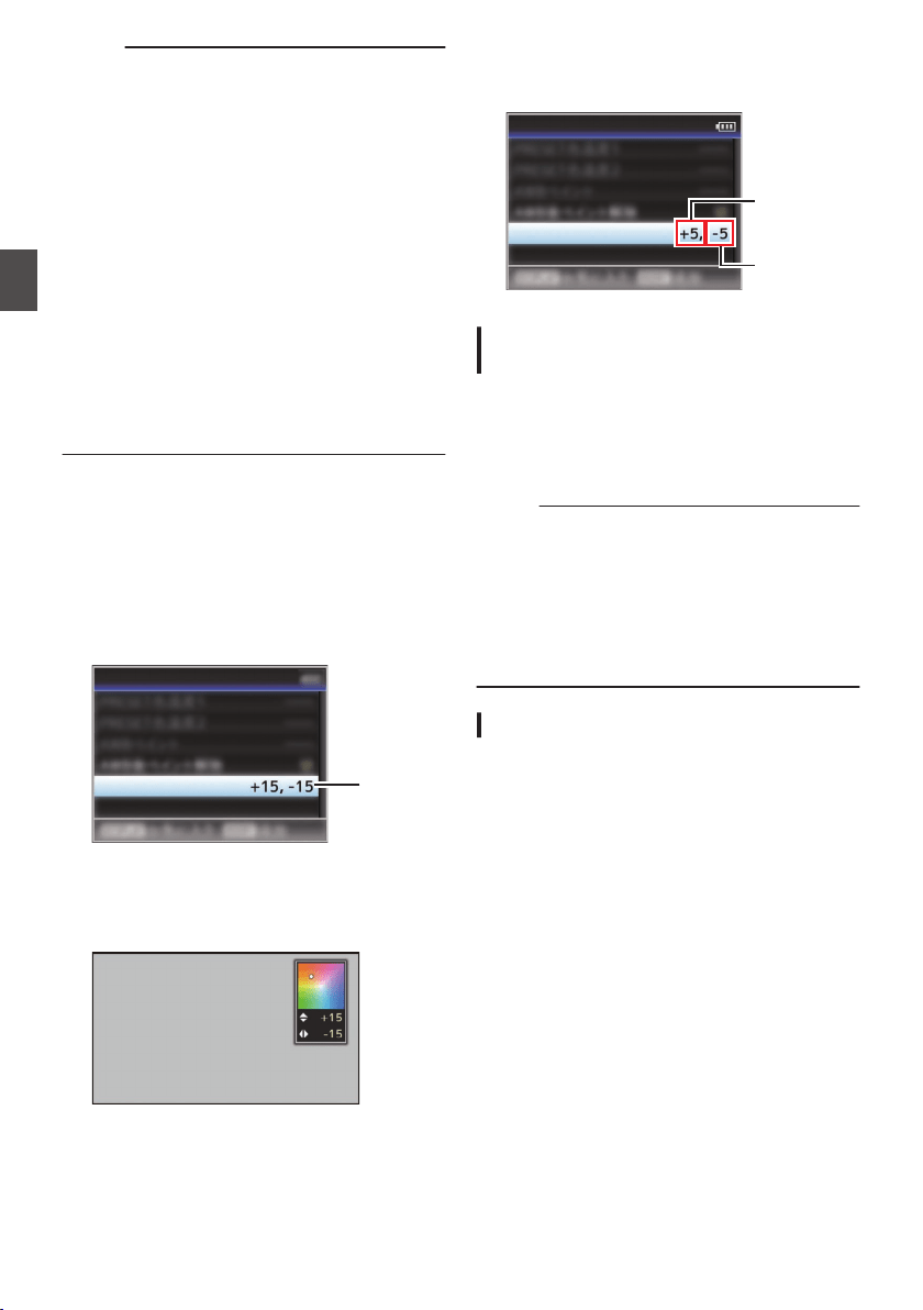
Memo :
0
Use the user button assigned with “Full Auto” to
enter the Full Auto mode also activates the
Automatic White Balance mode. In this case, the
Iris, Gain and Shutter also enter into Auto mode
forcibly.
0
The white balance operation during Full Auto
mode can be configured in [Camera Function]
B [Full Auto] B [White Balance].
0
When [Camera
Function] B [User Switch Set] B
[AE Lock] is set to “AE/FAW” or “FAW”, the white
balance when the user button that is assigned
with [AE Lock] is pressed can be fixed while in
the Automatic White Balance mode.
(A P113
[ AE Lock ] )
0
If [White Balance] is assigned to the user button,
pressing the assigned user button will display
the FAW Paint Adjustment screen.
(A P45 [Assignment of Functions to User
Buttons] )
FAW Paint Adjustment
You can fine-adjust the white balance that was
automatically adjusted.
1
Select [Camera Process]
B [White
Balance
]
B [FAW Paint] and press the Set
button (
R).
The FAW Paint Adjustment screen appears.
.
1
FAW Paint
White Balance
2
Adjust the R and B values.
Use the cross-shaped button (JK) to adjust R
value and (HI) to adjust B value.
.
B
R
3
Press the Set button (
R).
Returns to the [White Balance] screen.
.
B Value
R Value
FAW Paint
White Balance
Manual White Balance Mode (Manual
Switching)
1
Set Full Auto mode to off using the user
button assigned with “Full Auto”.
0
Use the [WHT.BAL] switch to select “PRST”
(preset mode), “A” (memory A mode), or “B”
(memory B mode).
Memo :
0
You can set the Full Auto White Balance feature
to either [A], [B], or [PRST] in [Camera
Function] B [FAW].
(A P
110 [ FAW ] )
0
The FAW (Full Time Auto White Balance) mode
makes automatic adjustments by sampling the
color temperature of the video to obtain the most
appropriate white balance level.
Preset Mode (PRST)
0
Two different color temperature settings are
registered on this camera recorder. You can
switch between them by pushing the [AWB/
USER8]
switch upward or using the user button
assigned with “AWB”.
Default setting:
[Preset Temp.
] : 3200K
[Alternative Temp.] : 5600K
1
Set the [WHT.BAL] switch to “PRST”.
2
Push the [AWB/USER8] switch upward or
press the user button assigned with the
“AWB” function.
0
The color temperature switches.
(“Preset Temp.
”1“Alternative Temp.”)
64
Adjusting the White Balance
Shooting
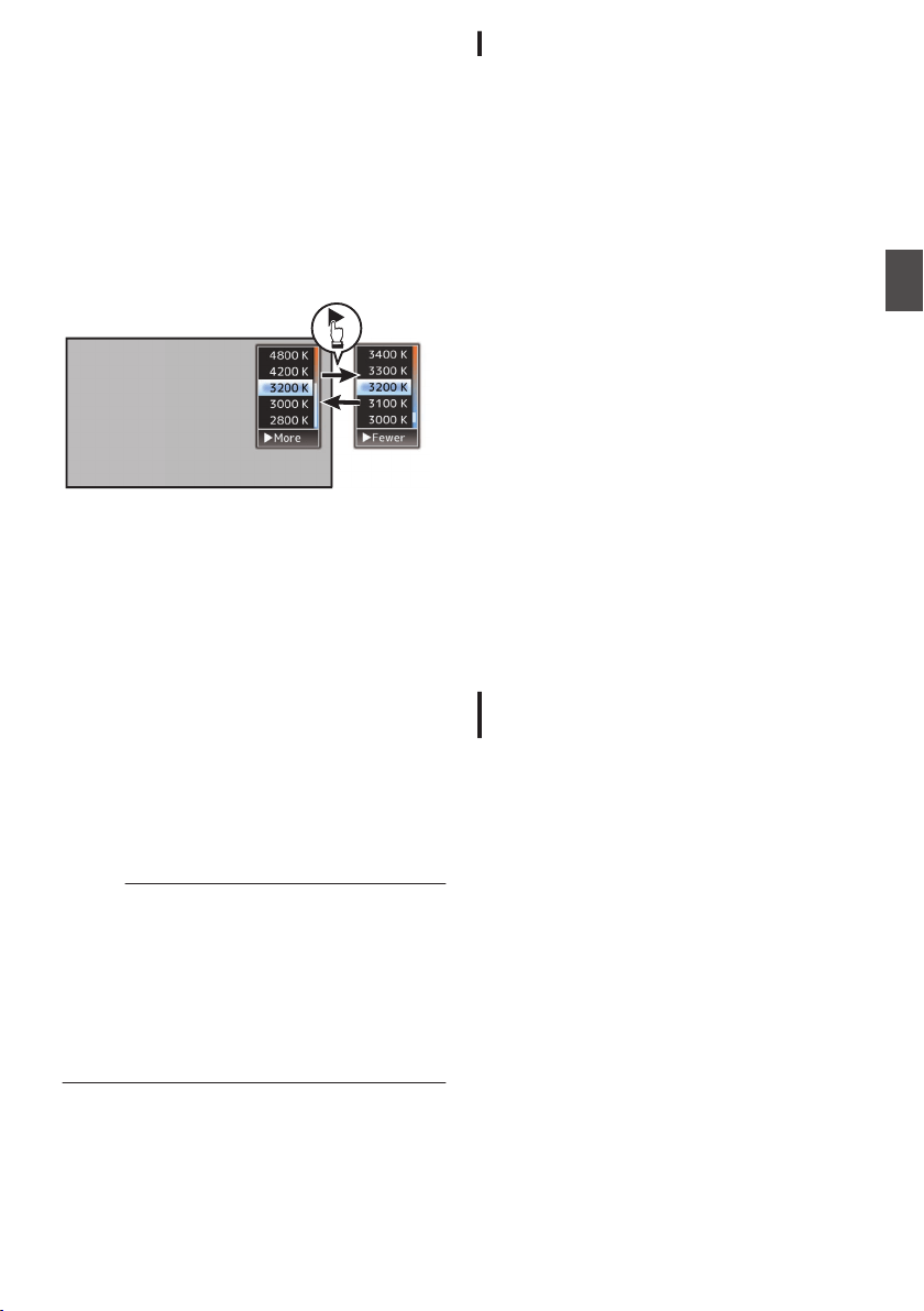
Setting the [Preset Temp.] or [Alternative
Temp.] Values
You can change both the color temperature
settings in the Preset mode in the menu.
1
Open the [Preset Temp.] or [Alternative
Temp.] menu.
0
Select
[Camera Process] B [White Balance]
B [Preset Temp.] and [Alternative Temp.],
and press the Set button (R).
0
The Color Temperature setting screen
appears.
.
Color Temperature
Detailed Selection
Screen
Color Temperature Selection Screen
2
Select the color temperature.
0
When selecting from a setting value (Color
Temperature Selection screen), use the
cross-shaped button (JK) to select the color
temperature.
[Setting Values: 7500K, 6500K, 5600K,
5200K, 4800K, 4200K, 3200K, 3000K,
2800K]
0
To select detailed values (Color
Temperature Detailed Selection screen)
0
Press the cross-shaped button (I) to
display the Color Temperature Detailed
Selection screen.
0
Use the cross-shaped button (JK) to
select a color temperature.
[Setting Values: 2300K to 15000K (in
100K increments)]
Memo :
0
Use the cross-shaped button (I) to switch
between the Color Temperature Selection
screen and the Color Temperature Detailed
Selection screen.
0
If [White Balance] is assigned to the user button,
pressing the assigned user button will display
the Color Temperature Selection screen.
(A P45 [Assignment of Functions to User
Buttons] )
Preset Paint Adjustment
The white balance for [Preset Temp.] and
[Alternative Temp.] can be fine adjusted
individually or collectively.
1
Select [Camera Process]
B [White
Balance]
B [Preset Paint Memory].
0
“Common” configures the settings for the
entire color temperature range collectively.
0
“Individual” configures the settings for the 9
types of color temperature individually.
2
Select [Camera Process]
B [
White
Balance]
B [Preset Paint].
0
The
adjustment screen appears if “Common”
is selected.
0
The lower color temperature limit of the color
temperature range is displayed if “Individual”
is selected. Select the color temperature to
adjust.
In the case of 2300K for example, the target
range is 2300K to 2900K (less than 3000K)
3
Adjust the R and B values.
0
Use the cross-shaped button (JK) to adjust
R value and (HI) to adjust B value.
4
Press the Set button (
R).
0
In the case of “Common”, the display returns
to the [White Balance] screen.
0
As for “Individual
”, repeat steps 1 to 4 as
necessary to configure each color
temperature individually.
Memory A Mode (A), Memory B Mode
(B)
0
Set to the white balance saved in Memory A or
Memory B.
0
When the
[
WHT.BAL] switch is set to “A” or “B”,
pushing the [AWB/USER8] switch upward or
pressing the user button assigned with the
“AWB” function executes Auto White Balance.
The white balance will be automatically adjusted
and the adjusted value will be saved in Memory
A or Memory B.
1
Prepare the camera recorder.
A
Set the [POWER ON/OFF] switch to “ON”.
B
Set Full Auto mode to off using the user button
assigned with “Full Auto”.
C
Set the [IRIS A/M] mode switch on the lens to “A”.
2
Set the [ND FILTER] switch according to the
lighting.
3
Set the [WHT.BAL] switch to “A” or “B”.
Adjusting the White Balance
65
Shooting
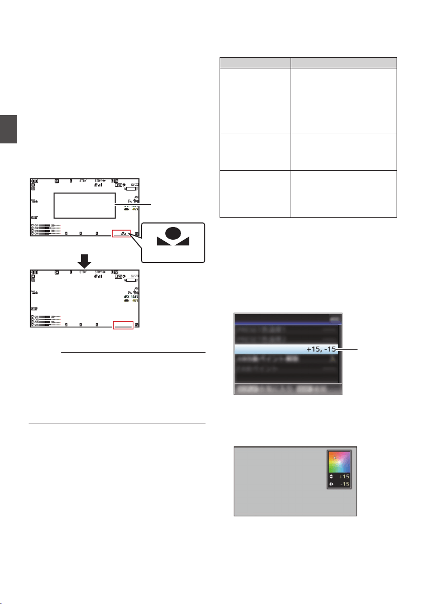
4
Locate a place with similar lighting conditions
as the object to be shot, place a white object
near the center of the screen and zoom in to
fill the screen with white.
5
Push the [AWB/USER8] switch upward or
press the user button assigned with the
“AWB” function.
0
The white detection frame appears when Auto
White Balance is activated. Fill the frame with
white completely.
0
While Auto White Balance is starting up,
“A
y
” or “B
y
” appears on the screen.
(
y
mark appears blinking)
0
After the correct white balance is obtained, an
estimated value of the current color
temperature is displayed.
.
100min
50min
282min
1
/60
F2. 8
AE
±0
ND1
/64
12 :34 : 56
ISO
102400
00: 00: 00.00
1080 /30p
SDI IN
ITU709
COMPRESS
5 . 6 f t
B
100min
50min
282min
1
/60
F2. 8
AE
±0
ND1
/64
12 :34 : 56
ISO
102400
00: 00: 00.00
1080 /30p
SDI IN
ITU709
COMPRESS
5 . 6 f t
B 5600
K
Result Display
[AWB] Activating
White Detection
Frame
Blinking
Caution :
0
Do not use highly reflective objects, such as
metals. Doing so may result in improper white
balance adjustment.
0
The Auto White Balance function cannot provide
optimum white balance with an object outside the
adjustment range, for example when it contains
only a single color or not enough white color.
Error Message
If the Auto White Balance adjustment is not
correctly completed, one of the following
messages will appear for about 3 seconds.
Message Status
Auto White * NG:
Object
(*A or B)
Displayed when there is not
enough white color on the
object, or when the color
temperature is not suitable.
Use
another white object and
adjust the white balance
again.
Auto White * Error:
Low Light
(*A or B)
Displayed when the lighting is
dark. Increase the lighting
and adjust the white balance
again.
Auto White * Error:
Over Light
(*A or B)
Excessive illumination.
Displayed
when the lighting is
too bright. Decrease the
lighting and adjust the white
balance again.
White Paint Adjustment
You can fine-tune the white balance saved in
Memory A or Memory B.
1
Select [Camera Process]
B [White
Balance
]
B [AWB Paint] and press the Set
button (
R).
The White Paint Adjustment screen appears.
.
1
AWB Paint
White Balance
2
Adjust the R and B values.
Use the cross-shaped button (JK) to adjust R
value and (HI) to adjust B value.
.
B
R
66
Adjusting the White Balance
Shooting

3
Press the Set button (
R).
Returns to the [White Balance] screen.
.
B Value
R Value
AWB Paint
White Balance
Memo :
0
Executing Auto White Balance will usually clear
the White Paint Adjustment value. But when
[Camera Process] B [White Balance] B [Clear
Paint After AWB] is set to “Off”, values will not
be cleared even when Auto White Balance is
executed.
(A P
123 [ Clear Paint After AWB ] )
0
If [White Balance] is assigned to the user button,
pressing the assigned user button will display
the AWB Paint Adjustment screen.
(A P45 [Assignment of Functions to User
Buttons] )
Vertical Shading Adjustment
0
Adjustment of white shading is needed when
you have changed the lens.
0
Although white balance may be appropriate at
the center of the image, this may not be the case
at the top and bottom areas.
If this is the case, the image will appear greenish
or yellowish. This phenomenon is due to the
characteristics of the lens. The process of
correcting this phenomenon is referred to as
vertical shading adjustment.
0
Perform this process after adjusting the white
balance.
Setup Prior Adjustment
1
Obtain the white balance on the camera.
(A
P65 [Memory A Mode (A), Memory B Mode
(B)] )
2
Set the control of the camera lens as
follows.
A
Set the iris to F4.0 or narrower to obtain the
appropriate brightness.
If
the
brightness is insufficient at F4.0, obtain the
appropriate brightness such as by adjusting the
lighting.
B
When using a zoom lens, set to the center of the
zoom adjustment range.
3
Fill the monitor screen with a pattern box of
a uniform light source, or a piece of white
(plain) paper that is uniformly illuminated.
4
Set the chroma level of the monitor to the
maximum.
5
Check the monitor screen.
0
There
is no need for adjustment if there is no
color at the top and bottom of the screen.
0
If the top of the screen is greenish and the
bottom is reddish or vice versa, continue this
adjustment.
Adjusting the White Balance
67
Shooting

Adjusting the Vertical Shading
1
Set [Camera Process]
B [White Balance
]
B
[V. Shading] to “On”.
2
Select [Adjust...] in [V. Shading] and press
the Set button (
R).
The Vertical Shading Adjustment screen
appears.
.
Setting
Value
Evaluated Value Detection Frames
Sliding Bar for Setting
Evaluated Level Meter
3
Press the [USER1] button to set to perform
automatic adjustment.
You can use the R, G, B channels individually
to adjust the value of the evaluated level meter
up to a margin error of ±1 from the median value.
4
Adjust manually.
0
If you want to adjust manually after automatic
adjustment is performed, follow the steps
below.
0
You are recommended to adjust the G
(green) level only.
0
If manual adjustment in not necessary,
adjustment is complete at step 7.
5
Use the cross-shaped buttons (
HI) to
select the item to adjust from [R]/[G]/[B].
6
Adjust the setting value using the cross-
shaped buttons (
JK).
0
Adjust the sliding bar for setting while
referring to the evaluated level meter.
0
Adjust the values such that the evaluated
value falls almost at the center of the meter
using the K cross-shaped button if the
evaluated
value of the channel to be adjusted
is larger than the median value, and the J
cross-shaped button if the evaluated value is
smaller than the median value.
7
Press the Set button (
R) to save the setting.
0
Make sure to press the Set button (R) to save
the setting.
0
Pressing the [CANCEL/RESET] button
discards the setting and returns to the menu
screen at the next higher level.
Memo :
0
There may be some delay in the changes of the
evaluated value after pressing the cross-shaped
button (JK).
0
Increasing the setting value suppresses the
colors at the bottom and enhances the colors on
top.
0
Adjustment is not possible in the following
cases. An error message will appear.
0
When the top and bottom ends of the frame
are overexposed
0
When the top and bottom ends of the frame
are underexposed
0
When there is significant difference in the
level between the top and bottom ends of the
frame
What is evaluated value?
This is a relative value (difference between the
top and bottom ends) with respect to the average
value of the R, G, B channels within the evaluated
value detection frames at the top and bottom of
the LCD monitor or viewfinder.
The evaluated value is positioned higher than the
center of the evaluated level meter when the level
at the top is higher than that at the bottom end.
Similarly, the evaluated value is positioned lower
than the center of the evaluated level meter when
the level at the top is lower than that at the bottom
end.
Adjust the evaluated value such that it falls
almost at the center of the meter.
68
Adjusting the White Balance
Shooting
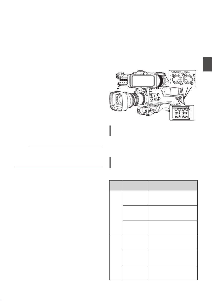
Adjusting the Camera
Image
The picture quality of the camera can be set using
the [Camera Process] menu.
As the adjustments are shown on the screen, you
can adjust the values while checking the picture
quality on the camera.
0
[Color Space
]
0
[Gamma]
0
[Detail
]
0
[Master Black]
0
[Black Paint
]
0
[Flare]
0
[V. Shading]
0
[Black Toe
]
0
[Knee Level
]
0
[Auto Knee Sensitivity]
0
[Auto Knee Peak Filter]
0
[White Clip]
0
[Chroma Clip]
0
[White Balance]
0
[Color Matrix]
0
[
Color Gain]
0
[Reverse Picture]
0
[DNR]
Memo :
0
For details of the respective items, see the
[Camera Process] menu.
(A P116 [Camera Process Menu] )
Audio Recording
You can record audio from the four channels (CH1/
CH2/CH3/CH4) in synchronization with the video
images on this camera recorder.
Select from the options below to record the audio.
0
Microphone connected to [MIC IN] terminal
(XLR 5-pin)
0
Microphone or line input connected to the
[AUDIO INPUT1] terminal (XLR 3pin)
0
Microphone or line input connected to the
[AUDIO INPUT2
] terminal (XLR 3pin)
.
P
R
AUDIO INPUT
DI
S
Setting the Number of Recording
Channels
0
Set the number of recording channels in
[System] B [Record Set] B [Record Format] B
[Audio].
Selecting Audio to Be Recorded in Each
Channel
Select the audio to be recorded in CH1/CH2/CH3/
CH4.
-
Switch
Setting
Connected Devices
CH1
CH3
FRONT
0
Audio input of
microphone 1 from
[MIC IN] terminal
REAR
0
Audio input from
[AUDIO INPUT1]
terminal
WIRELESS
0
Audio input of CH1
from the “UniSlot”
wireless receiver
CH2
CH4
FRONT
0
Audio input of
microphone 2 from
[MIC IN] terminal
REAR
0
Audio input from
[AUDIO INPUT2]
terminal
WIRELESS
0
Audio input of CH2 (or
CH1) from the “UniSlot”
wireless receiver
Adjusting the Camera Image
69
Shooting
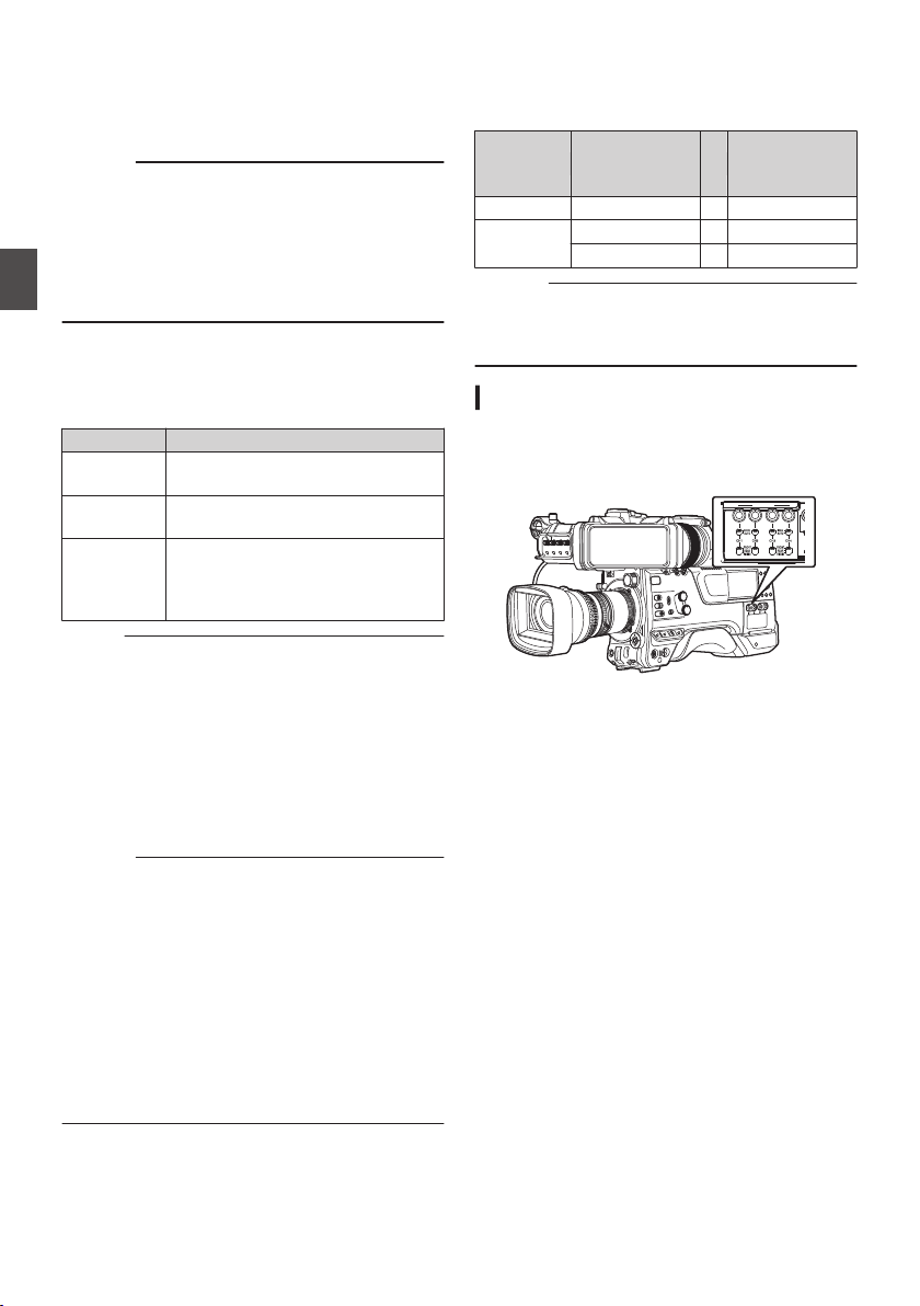
When the switch setting is set to “FRONT”
Audio recording is performed according to the
setting in [A/V Set] B [Audio Set] B [Front Mic
Select]/[Front Mic Power]
/[Front Mic 1 Ref.]/[Front
Mic 2 Ref.].
Caution :
0
Set [Front Mic Select] to “Stereo M/S” to convert
the audio signal to stereo (L/R) signal for
recording when a Mid/Side direct output
microphone is connected.
Do not set to “Stereo L/R” or “Mono” when an L/
R out stereo microphone or a monophonic
microphone is connected.
When the switch setting is set to “REAR”
Select the audio input to the [AUDIO INPUT 1/2]
terminal using the [AUDIO INPUT 1/2
] switch.
Setting Description
[LINE] Use this setting when connecting to
an audio device or other equipment.
[MIC] Use this setting when connecting to
a dynamic microphone.
[MIC+48V] Use this setting when connecting to
a microphone (phantom
microphone) that requires a +48 V
power supply.
Memo :
0
When “LINE” is selected, configure the
reference input level in [A/V Set] B [Audio Set]
B [Rear Line Ref.].
(A P135
[ Rear Line Ref. ] )
0
When “MIC” or “MIC+48V” is selected, set the
reference input level in [A/V Set] B [Audio Set]
B [Rear Mic 1 Ref.]/[Rear Mic 2 Ref.].
(A
P135 [ Front Mic 1 Ref. ] )
(A P135 [ Front Mic 2 Ref. ] )
Caution :
0
When connecting a device that does not require
a +48 V power supply, make sure that it is not
set to the “MIC+48V” position.
0
When the [AUDIO INPUT 1/2] switch is set to
“MIC”, make sure that a microphone is
connected
to the [AUDIO INPUT 1/2] terminal. If
you increase the recording level when a
microphone is not connected, noise from the
input terminal may be recorded.
0
When a microphone is not connected to the
[AUDIO INPUT 1/2] terminal, set the [AUDIO
INPUT 1/2] switch to “LINE”.
When the switch setting is set to “WIRELESS”
Recording is performed as follows according to the
setting in [A/V Set] B [Audio Set] B [Wireless
Channel].
“UniSlot”
Wireless
Receiver
Camera
Single: CH1
B
CH1/CH2
Dual: CH1
B
CH1
CH2
B
CH2
Caution :
0
Power is supplied to the
“UniSlot” wireless
receiver when any of the CH1/CH2/CH3/CH4
switches is set to “WIRELESS”.
Adjusting the Audio Recording Level
You can select to adjust the audio recording levels
for each of the four channels (CH1/CH2/CH3/CH4)
manually or automatically.
.
P
R
AUDIO INPUT
DI
S
70
Audio Recording
Shooting
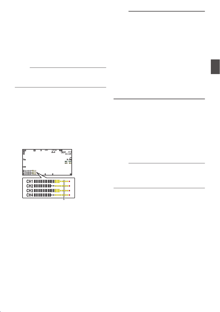
Manual Adjustment Mode (Manual
Adjustment)
0
The manual adjustment mode is enabled by
setting the [AUDIO SELECT CH1/2/3/4]-
[MANUAL/AUTO] selection switch on this
camera recorder to “MANUAL”. The audio level
for each channel can be configured in [A/V
Set] B [Audio Set] B [CH1 Audio Level](/2/3/4)
B [Front]/[Rear/Wireless].
0
You can adjust the level manually during the
recording, recording standby, and stop modes.
Memo :
0
The audio setting in Full Auto mode can be
configured in [Camera Function] B [Full Auto] B
[Audio Set].
1
Set the [AUDIO SELECT CH1/2/3/4]-
[MANUAL/AUTO] selection switch to
“MANUAL” for the channel to be adjusted
manually.
2
Turn the adjustment knob corresponding
to the channel to adjust the level.
When [A/V Set] B [
Audio Set] B [CH1/2 DRC]/
[CH3/4 DRC] B [Threshold Level] is set to “Off”,
adjust such that the audio level meter -2 dB
does not light up even for loud sounds.
(A P136 [ Threshold Level ] )
.
100min
50min
282min
1
/60
F2. 8
AE
±0
ND1
/64
12 :34 : 56
ISO
102400
00: 00 : 00.00
1080 /30p
SDI IN
ITU709
COMPRESS
5 . 6 f t
B 5600
K
-2dB
Memo :
0
The [Threshold Level], [Attack Time], [Decay
Time], [Mode], etc. of the compressor can be
configured in [A/V Set] B [Audio Set] B [CH1/2
DRC]/[CH3/4 DRC] for the audio to be recorded.
* DRC (Dynamic Range Compressor)
0
The limiter operates according to the setting in
[A/V Set] B [Audio Set] B [
Limitter] B [CH1](/
2/3/4).
When [Limitter] is set to “Off”, the limiter function
is disabled even when the [MANUAL/AUTO]
switch is set to “AUTO”. This may cause the
OVER indication of the level meter to light up.
0
The reference audio level is configured in
[A/V
Set] B [Audio Set] B [CH1/2 Audio Ref. Lv.]
(common for CH1/2)/[CH3/4 Audio Ref. Lv.]
(common for CH3/4).
Automatic Adjustment Mode
0
Set
the [AUDIO SELECT CH1/2/3/4]-[MANUAL/
AUTO] selection switch to “AUTO” or press the
user button assigned with “Full Auto” to set Full
Auto mode to off. This activates the Automatic
Adjustment mode and the audio recording level
is configured automatically according to the
input level.
0
The audio setting in Full Auto mode can be
configured
in [Camera Function] B [Full Auto] B
[Audio Set].
Memo :
0
If [A/V Set] B [Audio Set] B [CH1/2 DRC]/
[CH3/4 DRC] B [Threshold Level] is set to a
value other than “Off”, the compressor operates
according to the value set.
Audio Recording
71
Shooting
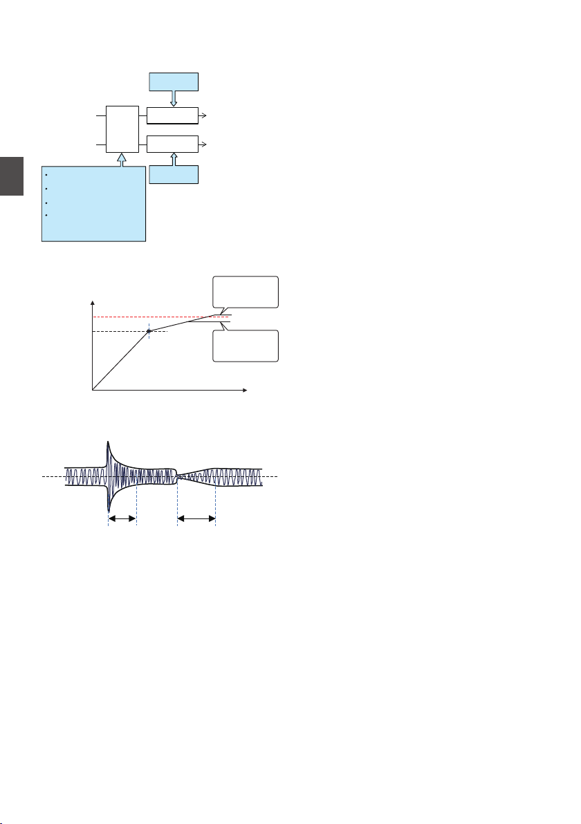
References on DRC (Dynamic Range
Compressor) and Limiter
DRC and Limiter Configuration Block Diagram
.
CH2
(CH4) In
CH1
(CH3) Out
CH2
(CH4) Out
Limiter
Limiter
On/Off
On/Off
DRC
Threshold
Attack Time
Decay Time
Mode
(Link/Separate)
CH1
(CH3) In
.
0dBFS
Figure 1
Operating Level of DRC and Limiter
Threshold
Limiter
On
Limiter
Off
CHx
In
CHx Out
.
Figure 2 DRC Response Characteristics
Decay TimeAttack Time
0
DRC Operation
This operation helps to prevent the recording
level from reaching saturation (0 dBFS) by
slowing down the gain changes when the
excessive sound input exceeds the threshold
level.
0
[CH1/2 DRC] and [CH3/4 DRC] settings
Threshold
Level
: This is the point when the gain
changes slowly. (See Figure 1)
Lowering the threshold level will
make it difficult for the recording
level to become saturated but this
will decrease the sound volume.
Attack
Time
: This is the response time from
when the sound exceeds the
threshold level until the level is
compressed. (See Figure 2)
“Fast” will result in fast response
time and “Slow” will result in slow
response time.
Decay
Time
: This is the response time from
when the excessive sound input
falls below the threshold level until
the level compression operation is
canceled. (See Figure 2)
“Fast” will result in fast response
time and “Slow” will result in slow
response time.
Mode : CH1 (CH3)/CH2 (CH4) operate
independently (mono) when
“Separate” is selected.
CH1 (CH3)/CH2 (CH4) operate in
tandem (stereo) when “Linked” is
selected. The level difference
between CH1 (CH3)/CH2 (CH4)
remains constant.
0
“Fast” and “Middle” in the Attack setting are
suitable for speech. “Middle”
and “Slow” are
suitable for music.
0
“Fast” and “Middle” in the Decay setting are
suitable for speech. “Middle
” and “Slow” are
suitable for music.
0
When using a stereo microphone with CH1
(CH3)/CH2 (CH4), configure the Mode
setting to
“Linked”.
To record different audio with CH1
(CH3)/CH2 (CH4), configure the Mode
setting to “Separate”.
0
Limiter Operation
A high speed response limiter that does not
exceed the saturation level (0 dBFS) for sharp
increase in the sound input not trackable by
DRC.
0
[Limitter] settings
On : Enables the limiter separately for
CH1/CH2/CH3/CH4.
Off
: Disables the limiter separately for
CH1/CH2/CH3/CH4.
AUTO/
MANUAL
SW Set
: The limiter is enabled when the
[MANUAL/AUTO] selection
switch is set to “AUTO” and
disabled when “MANUAL” is
selected.
72
Audio Recording
Shooting
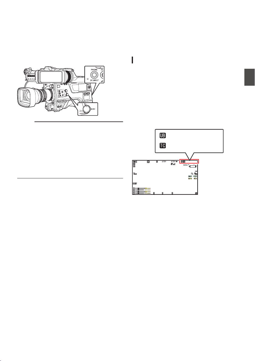
Audio Output during
Recording
0
You can check the recorded audio from the
monitor
speaker or the headphone connected to
the [PHONE] terminal.
0
Adjust the volume of the speaker or headphone
using the [MONITOR] volume adjustment knob.
.
Memo :
0
Warning tone is output when there is an
abnormality in the camera recorder or when the
battery is low.
(A P222 [Warning Tone] )
0
The volume of the warning tone can be adjusted
using the [ALARM] volume adjustment knob or
configured in [A/V Set] B [Audio Set] B [Min.
ALARM Level].
(A P137
[ Min. ALARM Level ] )
Time Code and User’s Bit
Time code and user’s bit data are recorded with the
video in this camera recorder.
The time code and user’s bit are displayed on the
viewfinder and LCD monitor during playback or
recording. (Display screen)
Displaying Time Code and User’s Bit
The time code and user’s bit are displayed on the
viewfinder and LCD monitor during playback or
recording.
The display differs according to the menu settings.
1
Set [LCD/VF]
B [Display On/Off] B [
TC/UB]
to “On”.
(A P
130 [Display On/Off Item] )
When “TC” or “UB” is selected, time code or
user’s bit data is displayed respectively on the
display screen.
.
100min
50min
282min
1
/60
F2. 8
AE
±0
ND1
/64
12 :34 : 56
ISO
102400
00: 00: 00.00
1080 /30p
SDI IN
ITU709
COMPRESS
5 . 6 f t
B 5600
K
00H 00M 00S 00F
AB CD EF 89
2
Select the display using the [TC DISPLAY]
TC/UB display switch.
Select time code display ([TC]) or user’s bit
display ([UB]).
Audio Output during Recording
73
Shooting
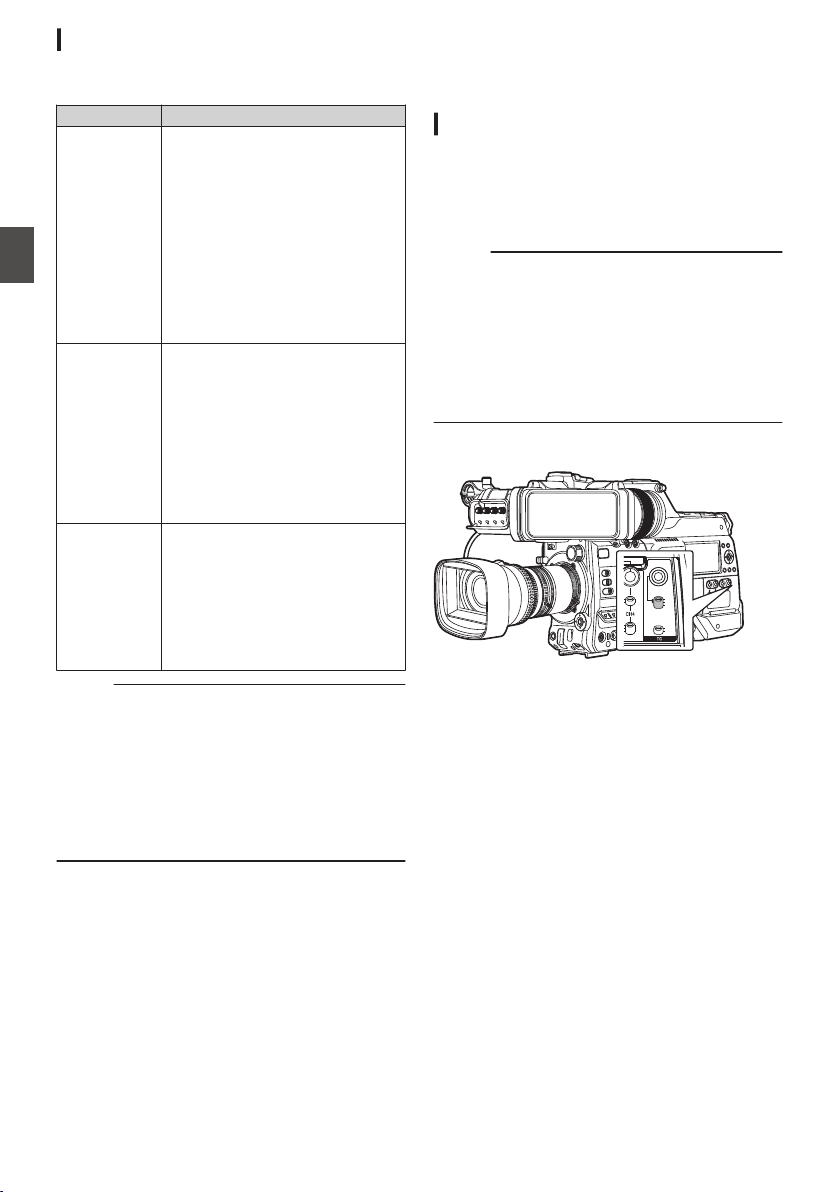
Time Code Operation Mode
Select the time code operation using the [TC
GEN] switch.
Setting Description
F-RUN The time code operates in the run
mode at all times regardless of the
recording status.
It continues to run even when the
power of the camera recorder is
turned off.
Synchronizes with the external
time code when an external time
code generator is connected.
(A P78 [Synchronizing the
Time Code with an External
Time Code Generator] )
R-RUN The time code operates in the run
mode during recording. It
continues
to run in the order of the
recorded clips as long as the SD
card is not replaced. If the SD card
is removed and recording is made
on another card, time code will be
recorded on the new card from
where it was left off in the previous
card.
REGEN The time code operates in the run
mode during recording. When the
SD card is replaced, the last time
code recorded on the card is read
and recorded on a new card so that
the time code continues in running
order.
(A P75 [Setting Time Code] )
Memo :
0
When [System] B [Record Set] B [Rec Mode] is
set to “Interval Rec”1 or “Frame
Rec”1, and the [TC GEN] switch is set to
“F-RUN”, R-RUN mode is activated.
0
When [System] B [Record Set] B [
Record
Format] B [System] is set to “High-
Speed”2, and the [TC GEN] switch is set
to “F-RUN”, R-RUN mode is activated.
Setting Time Code
Generator
Presetting the Time Code
Time code and user’s bit data generated from the
internal time code generator are recorded.
This section describes how to set
[TC/UB]
B [TC
Preset].
(A P124 [ TC Preset ] )
Memo :
0
When [System] B [Record Set] B [Record
Format] B [WFrame Rate] is set to “50p”, “50i”
or “25p”, setting for “Drop” will be disabled.
(A P152
[ W Frame Rate ] )
0
You can configure the setting without accessing
the [TC/UB] menu screen.
(A P76 [Setting Time Code without Opening
the Menu] )
Required Settings Before Preset
.
PRESET
TC
F-RUN
R-RUN
REGEN
UB
GEN
DISPLAY
1
Set the [TC GEN] switch to “R-RUN” or “F-
RUN
”.
0
[R-RUN]
Preset data in the time code generator
operates
in run mode during recording mode.
Set this when recording continuous time
code in connecting frames.
0
[F-RUN]
Time code starts to operate in run mode from
the preset time in the time code generator.
74
Time Code and User’s Bit
Shooting
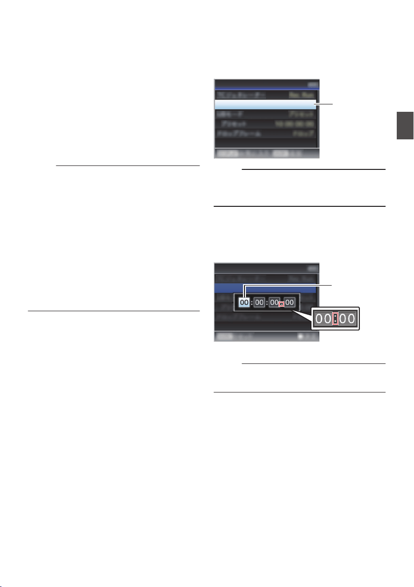
2
Select the framing mode for the time code
generator (only when the frame rate setting
is “60” or “30”).
To configure the setting, go to [TC/UB] B [Drop
Frame].
(A P
124 [ Drop Frame ] )
0
[Drop]:
Sets the run mode of the time code generator
to drop frame mode. Use this setting when
placing emphasis on the recording time.
0
[Non Drop]:
Sets the run mode of the time code generator
to non-drop frame mode. Use this setting
when placing emphasis on the number of
frames.
Memo :
Drop frame/non-drop frame mode
0
When [System] B [Record Set] B [Record
Format] B [Frame Rate] is set to “60p”, “60i”, or
“30p”, the actual number of frames per second
is approximately 59.94 (29.97). However, the
time code processing standard is “60p”, “60i”, or
“30p” frames. To make up for the frame number
discrepancy, the drop frame mode (Drop) drops
the 00 frame and 01 frame every minute except
for minutes that are multiples of 10. However, in
the case of “60p”, the 00, 01, 02 and 03 frame
are dropped.
0
The
non-drop frame mode (Non Drop) does not
drop frames and ignores the discrepancy with
the actual time.
Setting Time Code
1
Select [TC/UB]
B [TC Preset
] and press the
Set button (
R).
(A P124 [ TC Preset ] )
The [TC Preset] screen appears.
.
1
TC Preset
00:00:00:00
TC/UB
Memo :
0
When the [TC GEN]
switch is set to “REGEN”,
the parameter is displayed as “REGEN” and
selection is disabled.
2
Set the time code (hour, minute, second,
frame).
Use the cross-shaped button (HI) to place the
cursor at the item to set, then use the cross-
shaped button (JK) to change the values.
.
During drop frame
During non-drop
frame
Cursor
TC Preset
00:00:00:00
TC/UB
Memo :
0
Press the [USER3] button to reset each digit to
“0”. The cursor moves to the time digit (left).
3
Check the values and press the Set button
(
R).
0
The time code is set and the screen returns
to [TC/UB].
0
To cancel the setting, press the [CANCEL/
RESET] button.
4
Press the [MENU/THUMB] button.
Returns to the normal screen.
Setting Time Code Generator
75
Shooting
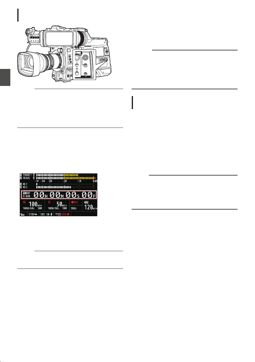
Setting Time Code without Opening the
Menu
.
PRESET
TC
F-RUN
R-RUN
REGEN
UB
GEN
DISPLAY
Memo :
0
Settings cannot be made in the following cases.
0
When the [TC GEN] switch is set to
“REGEN”.
0
Menu screen is displayed.
0
The camera recorder is not in the Camera
mode.
Setting Time Code
1
Set the [TC DISPLAY] switch to “TC”.
2
Set the [TC GEN] switch to a setting other
than “REGEN”.
3
Press the [TC PRESET] button.
.
4
Set the time code (hour, minute, second,
frame).
Use the cross-shaped button (HI) to place the
cursor at the item to set, then use the cross-
shaped button (JK) to change the values.
Memo :
0
Press the [CANCEL/RESET] button to reset
each digit to “0”. The cursor moves to the left.
5
Check the values and press the Set button
(
R).
0
The time code is set and the screen returns
to the normal screen.
0
To cancel the setting, press the [TC
PRESET] button.
Caution :
0
When
the
camera recorder is switched to Media
mode during editing, editing will be canceled
and the screen will close.
0
When editing the time code, operations of the
buttons configured in [Camera Function] B
[User Switch Set] are disabled.
Recording Time Code in Continuation of
the Recorded Time Code on SD Card
This camera recorder is equipped with the time
code reader.
1
Set the [TC GEN] switch to “REGEN”.
0
When the camera recorder enters from
recording standby mode to recording mode,
it reads the time code already recorded on
the SD card and records the new time code
in continuation of that value.
0
The same data as the user’s bit already
recorded on the SD card is recorded.
Memo :
0
When the [TC GEN] switch is set to “REGEN”,
the framing mode of the time code follows the
settings in [TC/UB] B [Drop Frame]
instead of
the clip settings.
(A P124
[ Drop Frame ] )
76
Setting Time Code Generator
Shooting
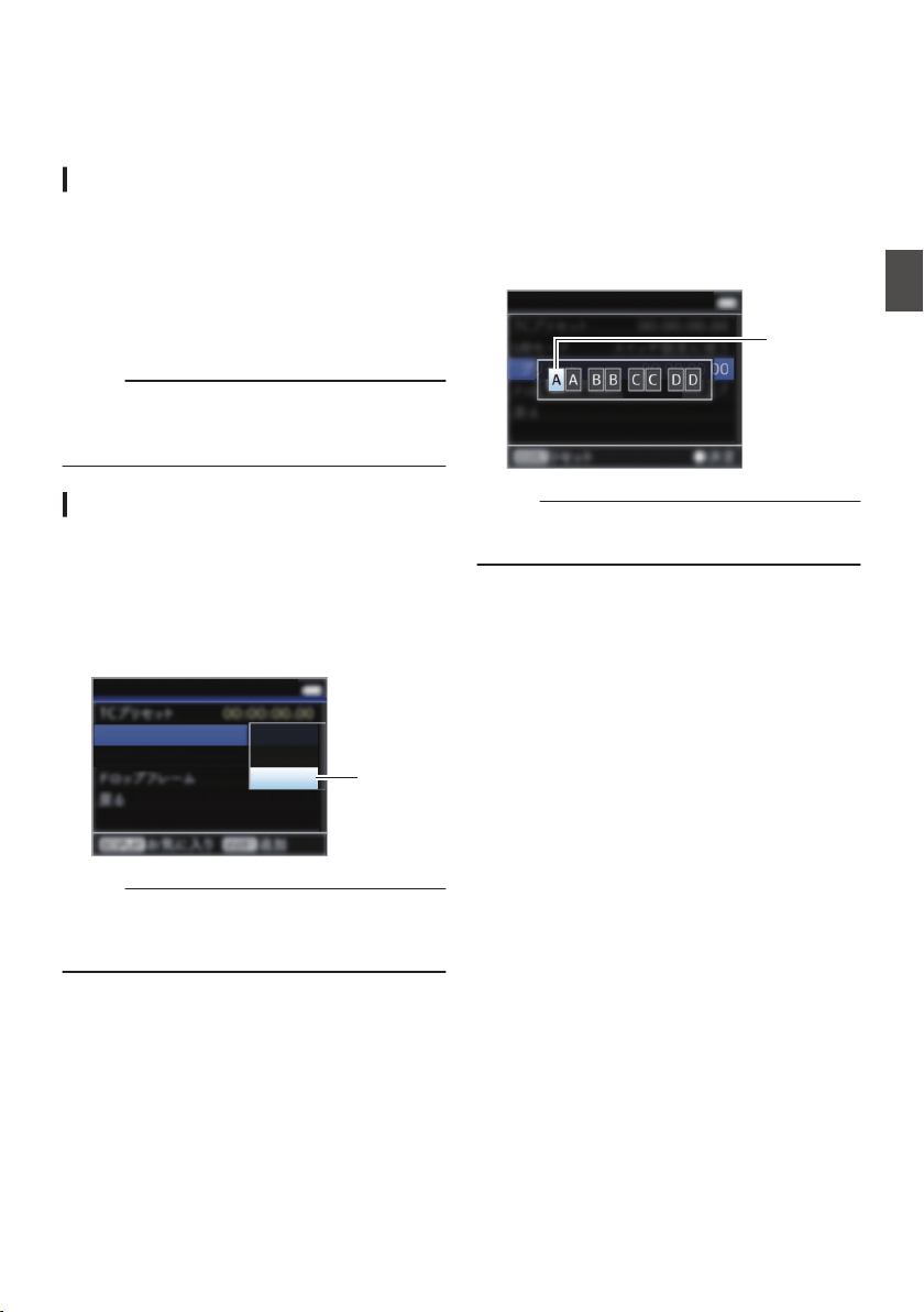
Setting the User’s Bit
You can add the date, time or an 8-digit
hexadecimal number as the user’s bit to the
recorded image.
Selecting a Recording Mode
Recording date/time information to the user’s
bit
1
Set [TC/UB]
B [UB Mode] to “Date” or
“Time”, and press the Set button (
R).
(A P124
[ UB Mode ] )
The date or time information is recorded to the
user’s bit.
Memo :
0
When “Date” or “Time” is set, [Preset] appears
as “-” and cannot be set.
0
“Time”
is displayed in the 24-hour format.
Presetting the User’s Bit
Recording arbitrary information (8-digit
hexadecimal) to the user’s bit
1
Set [TC/UB]
B [UB Mode] to “Preset”, and
press the Set button (
R).
(A P124 [ UB Mode ] )
.
1
TC/UB
UB Mode
Preset
Time
Preset
Date
Memo :
0
When the [TC GEN] switch is set to “REGEN”,
the parameter is displayed as “REGEN” and
selection is disabled.
2
Select [TC/UB]
B “Preset” and press the Set
button (
R).
The [Preset] setting screen appears.
3
Use the cross-shaped button (
HI) to place
the cursor at the item to set, then use the
cross-shaped button (
JK) to change the
values.
Numbers between 0 and 9 or alphabets
between A and F can be specified for the user’s
bit.
.
TC/UB
Cursor
Memo :
0
Press the [CANCEL/RESET] button to reset each
digit to “0”. The cursor moves to the left.
4
Check the values and press the Set button
(
R).
0
The user’s bit is set and the screen returns to
[TC/UB].
0
To cancel the setting, press the [CANCEL/
RESET] button.
5
Press the [MENU/THUMB] button.
Returns to the normal screen.
Setting the User’s Bit
77
Shooting
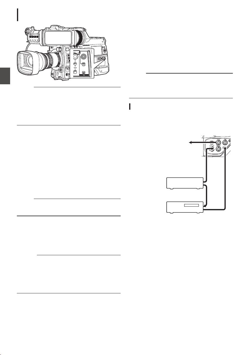
Setting User’s Bit without Opening the
Menu
.
PRESET
TC
F-RUN
R-RUN
REGEN
UB
GEN
DISPLAY
Memo :
0
Settings cannot be made in the following cases.
0
When the [TC GEN] switch is set to
“REGEN”.
0
Menu screen is displayed.
0
The camera recorder is not in the Camera
mode.
Setting the user’s bit
1
Set the [TC DISPLAY] switch to “UB”.
2
Set the [TC GEN] switch to a setting other
than “REGEN”.
3
Press the [TC PRESET] button.
4
Set the user’s bit (numbers between 0 and
9, or alphabets between A and F).
Use the cross-shaped button (HI) to place the
cursor at the item to set, then use the cross-
shaped button (JK) to change the values.
Memo :
0
Press the [CANCEL/RESET] button to reset
each digit to “0”. The cursor moves to the left.
5
Check the values and press the Set button
(
R).
0
The
user’s bit is set and the screen returns to
the normal screen.
0
To cancel the setting, press the [TC
PRESET] button.
Caution :
0
When the camera recorder is switched to Media
mode during editing, editing will be canceled
and the screen will close.
0
When editing the user’s bit, operations of the
buttons configured in [Camera Function] B
[User Switch Set] are disabled.
Synchronizing the Time
Code with an External
Time Code Generator
This camera recorder comes with a [TC IN]
terminal.
Connect a time code signal generator to the [TC
IN] terminal to synchronize with the SMPTE/EBU
LTC time code.
Memo :
0
After synchronization (slave lock), the internal
time code generator continues to run even if
there is no input from the external time code
generator.
Connection
Setting up the external time code generator as
a master device
.
GENLOCK
TC OUT
TC IN
To [TC IN] Terminal
of Another Camera
LTC Time Code
External Synchronizing Signal
External Synchronizing Signal
Master Device
External Time
Code Generator
Sync Signal
Generator
Slave Device
78
Setting the User’s Bit
Shooting
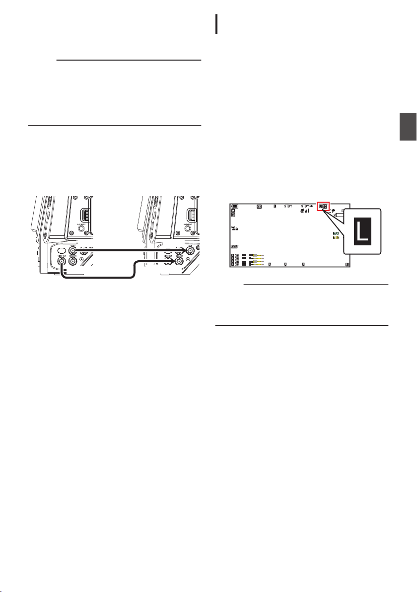
1
Input the external synchronizing signal to
the external time code generator and the
[GENLOCK] terminal of this camera
recorder.
Memo :
0
BB signals or HDTV tri-level synchronizing
signals are used as the external synchronizing
signal.
0
If the power of the camera recorder is turned on/
off during input of external synchronizing
signals, the screen may appear disrupted for a
few seconds. This is not a malfunction.
2
Input the SMPTE/EBU LTC time code from
the external time code generator to the [TC
IN] terminal of this camera recorder.
Connecting multiple devices, with one as the
master unit and the others as slave units
.
TC OUT TC IN
GENLOCK
VIDEO OUT
Master Device
Slave Device
1
Connect the [TC OUT] terminal of the
master device with the [TC IN] terminal of
the slave device.
2
Connect the [VIDEO OUT] terminal of the
master device with the [GENLOCK]
terminal of the slave device.
Settings and Operation of the Camera
Recorder
1
Set to Camera mode.
(A P20 [Operation Modes] )
2
Set [A/V Set]
B [
Video Set]
B [Genlock
Input] to “GENLOCK”.
(A P134
[ Genlock Input ] )
3
Set the [TC GEN] switch to “F-RUN”.
4
Set LCD monitor or viewfinder to Display
screen.
5
Set the external time code generator or the
master device, and run the time code.
0
When the built-in time code generator is
synchronized with the external time code
data
input, the Z icon on Display screen lights
up.
0
When time code is not synchronized or time
code input is not available, the Z icon goes
out.
.
100min
50min
282min
1
/60
F2. 8
AE
±0
ND1
/64
12 :34 : 56
ISO
102400
00: 00:00.00
1080 /30p
SDI IN
ITU709
COMPRESS
5 . 6 f t
B 5600
K
Memo :
0
The built-in time code generator will continue
operation even when the master device is
disconnected after synchronization.
0
User’s bit will become data in the master device.
Synchronizing the Time Code with an External Time Code Generator
79
Shooting
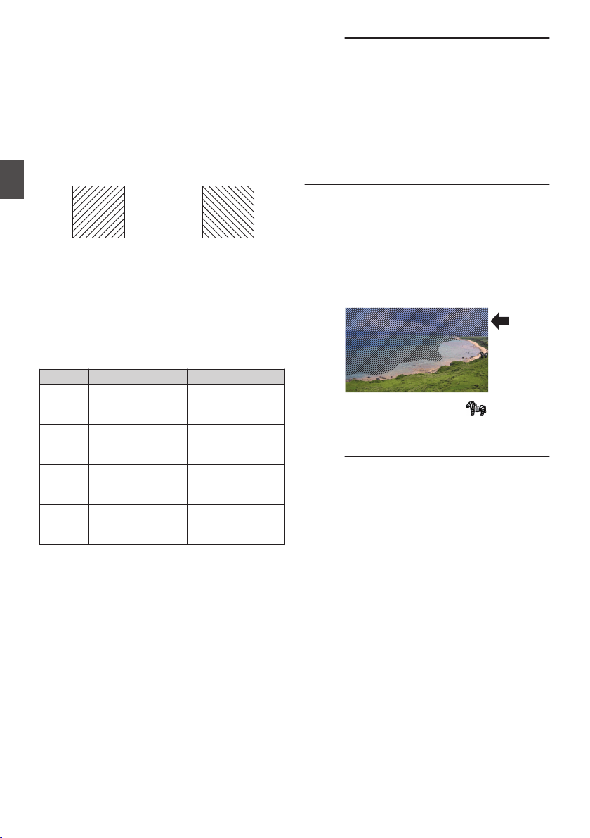
Setting Zebra Pattern
When the luminance level range for displaying
zebra patterns is specified, diagonal lines (zebra
pattern) are displayed at areas with the specified
luminance levels during shooting.
1
Set the zebra display pattern.
Select the display pattern in [LCD/VF] B
[Shooting Assist] B [Zebra].
(A P
126 [ Zebra ] )
.
Zebra 2 Display
Example
Zebra 1 Display
Example
2
Specify the brightness (luminance) level
range for displaying zebra pattern.
Set the maximum brightness limit in [LCD/VF]
B [Shooting Assist] B [Zebra] B [Top 1]/[Top
2],
and the minimum brightness limit in [Bottom
1]/[Bottom 2].
Item Settings Options
Top 1 Maximum
brightness limit for
displaying Zebra 1
5%, 10% to 95%,
98%, 100%, Over
Bottom 1 Minimum
brightness limit for
displaying Zebra 1
0%, 5% to 95%,
98%, 100%
Top 2 Maximum
brightness limit for
displaying Zebra 2
5%, 10% to 95%,
98%, 100%, Over
Bottom 2 Minimum
brightness limit for
displaying Zebra 2
0%, 5% to 95%,
98%, 100%
Memo :
0
When [Zebra] is set to “1 Pattern”, “Top 2” and
“Bottom 2” cannot be selected.
0
If the area specified by two zebra patterns
overlaps, Zebra1 pattern will be displayed.
0
The timing to detect the zebra pattern display
can
be configured only when “J-Log1” or “HLG”
is selected in [Color Space] and “Cam” or “Cam
+ Return” is selected in [Convert to ITU709].
(A P
116 [ Color Space ] )
(A P126 [ Detect ] )
3
Display the zebra pattern.
0
When
the
viewfinder is connected, the zebra
pattern is displayed when the [ZEBRA]
switch is set to “ON” or push down to
“MOMENT”.
0
When the viewfinder is not connected, the
zebra pattern is displayed using the user
button assigned with “Zebra”.
.
During zebra pattern display, (zebra icon)
is displayed on the display screen in Camera
mode.
Memo :
0
When the viewfinder is connected, priority is
given to the [ZEBRA] switch on the viewfinder
so
the
user button assigned with “Zebra” will not
function.
80
Setting Zebra Pattern
Shooting

Setting Spot Meter
The brightness of the object during shooting is
displayed.
This function is useful when setting video or stage
lighting or when specifying camera exposure.
A cursor indicating the location and the brightness
(%) of that location are displayed in the images
shown on the LCD monitor and viewfinder screen.
0
Zebra patterns display the brightness of output
video signals.
(A P80 [Setting Zebra Pattern] )
0
This function allows you to check the brightness
of input images from the lens without depending
on image processing such as gamma curve.
0
When [Color Space] is set to a value other than
“HLG” and “J-Log1”, the dynamic range of the
camera recorder is max. 600% and a brightness
range of 0% to 600% is displayed.
0
The value of the spot meter changes according
to the setting of [LCD/VF
] B [Convert to
ITU709]/[White Level] when [Color Space] is set
to “HLG”.
When [Color Space] is set to “HLG” and
[LCD/VF] B [Convert to ITU709]/[White Level] is
set to “72.5%”, the dynamic range of the camera
recorder is max. 687% and a brightness range
of 0% to 687% is displayed.
0
When [Color Space] is set to
“J-Log1”, the
dynamic range of the camera recorder is max.
800% and a brightness range of 0% to 800% is
displayed.
Memo :
0
Spot meter may not be consistent with the zebra
display range.
1
Select one of the following from [Camera
Function]
B [User Switch Set] B [Spot
Meter].
(A P
113 [ Spot Meter ] )
Item Settings
Color of Frame
Indicating the
Position
Max & Min
Displays the
brightness (%)
and positions of
the brightest and
darkest areas in
the screen.
Frames may also
be stopped at the
current positions.
0
Max: Green
0
Min: Yellow
Max Displays the
brightness (%)
and
position of the
brightest area in
the screen.
Frames may also
be stopped at the
current positions.
Green
Min Displays the
brightness (%)
and position of the
darkest area in the
screen. Frame
may also be
stopped at the
current positions.
Yellow
Manual Displays the
brightness (%) of
the specified
position.
Green
(Blinks in green
when
specifying
the position)
2
Assign the “Spot Meter” function to any of
the user buttons.
(A P45 [Assignment of Functions to User
Buttons] )
3
Press the user button that is assigned with
“Spot Meter”.
The operation switches as below when the
button is pressed.
Setting Spot Meter
81
Shooting

When [Max & Min]/[Max]/[Min] is selected
A
The cursors appear according to the setting
when the button is pressed.
Green and yellow frames appear, and the
brightness levels of these areas are displayed.
.
Cursor
Cursor
Brightness
Indication
(Yellow)
(Green)
B
Hold down the button in the state in A, the
positions of the brightest (Max) and darkest
(Min) areas in the screen are automatically
detected with regard to the changes of the
object, and the brightness level of these areas
are displayed.
.
(Min: Yellow)
Cursor
(Max: Green)
Cursor
Brightness
Indication
C
Pressing the button in the state in B stops the
automatic position detection. The frames are
fixed at the stopped positions and the
brightness levels are displayed.
D
By pressing the button, the cursors and
brightness indication disappear.
.
When [Manual] is selected
A
The brightness of the cursor position is
displayed when the button is pressed.
.
Cursor
(Green)
Brightness
Indication
B
By pressing the button, the cursors and
brightness indication disappear.
.
C
Hold down the button in the state in A or B, the
cursor blinks in green.
Move the cursor with the cross-shaped button
(JKHI) to specify the position to display the
brightness.
When you decide on the position, press the Set
button (R) to confirm.
.
(Blinks in
green)
Cursor
Brightness
Indication
D
Frames are fixed at the stopped positions and
the brightness is displayed.
Memo :
0
When moving the cursor position,
[Shutter]/[AE
Level] control is disabled.
0
When
the brightness is 0 % in the entire screen,
the frame is fixed in the center.
82
Setting Spot Meter
Shooting
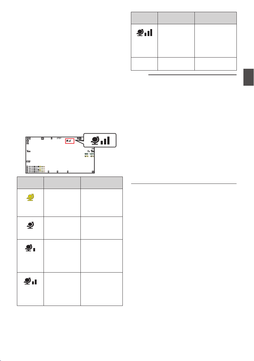
Acquiring Positioning
Information by GPS v
u
This camera recorder comes with a built-in GPS
function. The GPS function is able to record the
positioning information.
During playback, you can also display the recorded
information on the playback screen.
(A P99 [Playing back] )
1
Set [System]
B [
GPS] to “On”.
0
Positioning starts when the H icon on the
display screen starts blinking.
0
After positioning is complete, the H icon
switches to a solid light and records the
positioning information during shooting.
0
The icon that appears on the screen changes
according to the condition of signal reception
from the GPS satellite.
.
100min
50min
282min
1
/60
F2. 8
AE
±0
ND1
/64
12 :34 : 56
ISO
102400
00: 00:00.00
1080 /30p
SDI IN
ITU709
COMPRESS
5 . 6 f t
B 5600
K
Display
Reception
Status
Positioning Status
.
(Yellow)
[GPS] is set to
“On”, but signal
cannot be
received
GPS signal cannot
be received. UTC
and positioning
information cannot
be obtained.
.
(Blink)
GPS search in
progress
UTC information
can be obtained,
but not positioning
information.
.
GPS reception
in progress
(signal strength:
weak)
Receiving weak
GPS signal. UTC
and positioning
information can be
obtained and
recorded.
.
GPS reception
in progress
(signal strength:
medium)
Receiving GPS
signal. UTC and
positioning
information can be
obtained and
recorded.
Display
Reception
Status
Positioning Status
.
GPS reception
in progress
(signal strength:
strong)
Receiving strong
GPS signal. UTC
and positioning
information can be
obtained and
recorded.
(No
display)
GPS function is
turned off
The [GPS] item is
set to “Off”.
Memo :
0
If positioning cannot be performed after waiting
for several minutes, this means GPS reception
is poor, and there is difficulty in receiving data.
Move to an open place with no obstructions.
Otherwise, GPS information will not be recorded
when shooting is performed.
0
Signal may not be received depending on
circumstances such as locations that are
indoors or surrounded by tall buildings, or the
geographical conditions.
Precision error may occur in the position
information depending on the conditions of
reception.
0
Even when positioning is in progress,
information may be disrupted depending on the
condition of signal reception.
0
When [A/V Set] B [Video Set] B [SDI OUT1
Res.] is set to “1080p”, configuring [System] B
[GPS] to “On” changes the setting to “1080i”.
Acquiring Positioning Information by GPS v u
83
Shooting

Viewing Recorded Videos
Immediately (Clip Review)
You can check (review) the last recorded video clip
on the screen.
However, the video clip cannot be played back if
the settings of the camera recorder are different
from the video format (Resolution/Frame Rate/Bit
Rate/SD Aspect) of the clip.
(A P152 [ W Resolution ] )
(A P152 [ W Frame Rate ] )
(A P153 [ W Bit Rate ] )
(A P154 [ SD Aspect 2 ] )
Memo :
0
To use this function, assign “Clip Review” to any
of the user buttons.
1
Press the user button assigned with the
“Clip Review” function during standby
(“STBY” is displayed).
Playback of the configured section starts.
Memo :
0
The video clip is played back according to the
setting in [Camera Function] B [User Switch
Set] B [Clip Review]. By default setting (Last
5sec), the last 5 seconds of the clip is played
back.
(A P113
[ Clip Review ] )
0
When playback is complete, the camera
recorder exits Clip Review and returns to
“STBY” (recording standby) mode.
Caution :
0
During Clip Review, only the [CANCEL/
RESET] and [REC] buttons are enabled.
Press the [CANCEL/RESET] button to cancel
clip review and return to “STBY” (recording
standby) mode.
Press the [REC] button to cancel clip review and
enter recording mode. It will take some time to
start recording after the button is pressed.
0
When the last clip is less than 5 seconds, the
whole clip is played back.
0
Only
video clips in the currently selected slot can
be reviewed.
0
When there are no clips in the selected slot, Clip
Review function is disabled.
0
Clip Review is unavailable when Clip
Continuous Rec is paused (“STBYC”, yellow
text). To operate Clip Review, use the
[CANCEL/RESET] button to set to “STBYC”
(white text) first.
(A P91 [Clip Continuous Rec 0] )
0
Clip Review is unavailable when the camera
recorder is connected to an external equipment
and the equipment is in recording state.
0
Clip Review is unavailable when operating View
Remote via network connection.
(A P202 [View Remote Control and Camera
Control Functions] )
0
Clip Review does not function during live
streaming.
0
Clip Review does not function while the record
trigger is in the REC state.
84
Viewing Recorded Videos Immediately (Clip Review)
Shooting
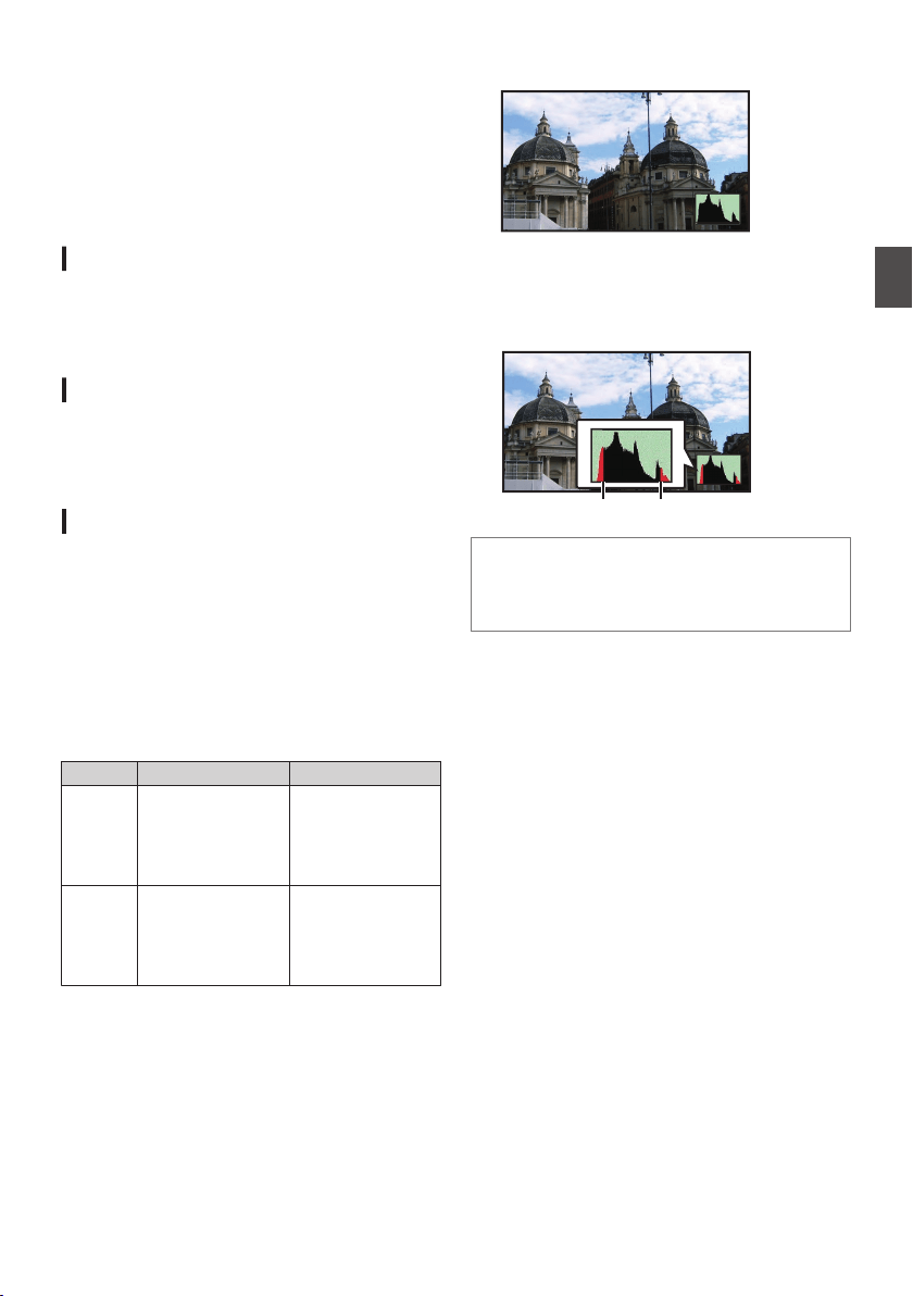
Displaying the Video
Signal Monitor
The video signal monitor can be displayed using
the user button assigned with “Video Signal
Monitor”. The display operation functions
according to the setting in [Camera Function] B
[User Switch Set] B [Video Signal Monitor].
Displaying the Vectorscope
Displays the saturation and hue of the video as a
circle.
The vectorscope can be displayed using the user
button assigned with “Video Signal Monitor”.
Displaying the Waveform
Displays the luminance signal of the video as a
waveform.
The waveform can be displayed using the user
button assigned with “Video Signal Monitor”.
Displaying the Histogram
2
The histogram shows the brightness distribution,
and is employed mainly for checking the exposure
of the image.
1
Set the histogram feature to ON.
The histogram can be displayed using the user
button assigned with “Video Signal Monitor
”.
2
Set the upper and lower limits of the
histogram display.
After setting, the brightness level is displayed in
red color.
Item Settings Options
Top Sets the maximum
brightness limit for
changing the
histogram display
color
5% to 110% (in 5 %
increments)
Bottom Sets the minimum
brightness limit for
changing the
histogram display
color
0% to 105% (in 5 %
increments)
o When the upper limit is set to 110% and the lower
limit to 0%
.
* The area in red is not displayed.
o When
the upper limit is set to 90% and the lower
limit to 10%
.
To p
Bottom
How to read the histogram
0
The
vertical axis denotes the number of pixels.
0
The horizontal axis denotes the pixel
brightness.
Displaying the Video Signal Monitor
85
Shooting
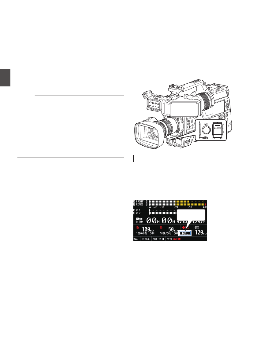
Recording
Simultaneously at Two
Different Definitions
2
By setting [System] to “HD+Web”, you can record
simultaneously at two different definitions.
0
When HD+Web is selected:
Records a high-definition (HD) file to slot A and
a web file to slot B at the same time.
Web files
can be used as a proxy file for the HD
file.
Memo :
0
If
a recordable SD card is inserted into only one
of the slots, files will only be recorded to that slot.
0
The [Rec Mode] is fixed at “Normal”.
0
Clip Cutter Trig is disabled.
0
[Slot Mode] cannot be selected.
0
Clip Review can only be performed for slot A.
(“No Media” appears if there is no card in slot A
while a card is inserted into slot B.)
0
Playback of web files is only possible from slot
B when “HD+Web” is selected.
Series Rec
0
Series Rec mode is specified in the factory
default.
([System] B [Record Set] B [Slot Mode] is set to
“Series”.)
(A
P155 [ Slot Mode ] )
0
If both the slots are loaded with recordable
cards, pressing the [REC] button starts
recording only to the media in the selected slot.
When the remaining space in the selected
media runs out, recording continues by
automatically activating the media in the other
slot.
0
There is no indication on the display screen
when the Series Rec mode is set.
Dual Rec
0
If both the slots are loaded with recordable cards
in the Dual Rec mode ([Slot Mode] is set to
“Dual”), pressing the [REC] button starts
recording simultaneously to the media in both
the slots.
0
The
clips recorded to the media in both the slots
are identical, and two clips of the same content
can be created only on this camera recorder.
(A P155 [ Slot Mode ] )
.
Setting to Dual Rec Mode
1
Set [System]
B [
Record Set]
B [Slot Mode]
to “Dual”.
(A
P155 [ Slot Mode ] )
“DUAL” appears on the enlarged display
screen.
.
DUAL
86
Recording Simultaneously at Two Different Definitions 2
Shooting
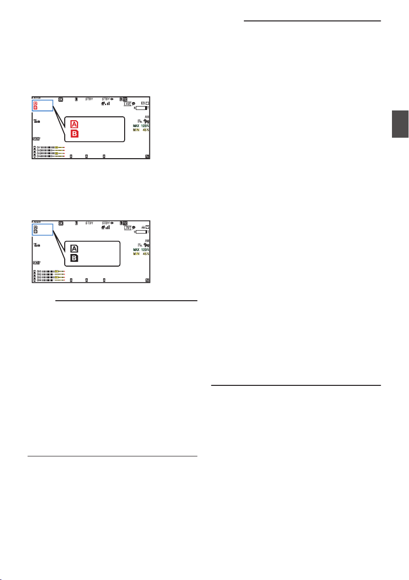
2
Start recording.
0
Insert recordable media in both slots, and
press the [REC] button.
0
In the Dual Rec mode, recording to the media
in both slots starts at the same time.
0
Both the card slot marks turn red, and the
status indicators of both the card slots also
light up in red.
.
100min
50min
282min
1
/60
F2. 8
AE
±0
ND1
/64
12 :34 : 56
ISO
102400
00: 00:00.00
1080 /30p
SDI IN
ITU709
COMPRESS
5 . 6 f t
B 5600
K
Lit in red
3
Stop recording.
0
Press the [REC] button again.
0
Recording to both slots stops, and both the
card slot marks turn white.
0
The same clips are recorded to both cards.
.
100min
50min
282min
1
/60
F2. 8
AE
±0
ND1
/64
12 :34 : 56
ISO
102400
00: 00:00.00
1080 /30p
SDI IN
ITU709
COMPRESS
5 . 6 f t
B 5600
K
White
Memo :
0
During recording in the Dual Rec mode, both the
card slot marks light up in red.
0
During recording in the Dual Rec mode to two
cards with a different amount of remaining
space, if the space of one card runs out,
recording to both slots will stop automatically.
After recording stops, recording automatically
resumes for the card with remaining space.
Although the clips are separated in this case, the
clips can be seamlessly joined by arranging
them on the timeline of the editing software since
they are recorded seamlessly.
0
If the last clip on the cards that are inserted in
the two slots are different from each other, and
the time code operating mode is set to
“REGEN”, the REGEN mode for the selected
card slot will be enabled in the next recording.
Caution :
0
To perform recording in the Dual Rec mode, it is
recommended that you start recording by
making use of two cards with the same capacity
and from the formatted state.
0
You can combine the use of the Dual Rec mode
with a special recording mode. While in the Dual
Rec mode, you can also set [Rec Mode] to
“Normal”, “Pre Rec”, “Clip Continuous”, “Interval
Rec”, or “Frame Rec”.
(A P
90 [Special Recording 0] )
(A P154 [ Rec Mode 0 1 ] )
0
When both slots are inserted with recordable
cards, the Dual Rec (simultaneous recording)
operation can be performed. If a recordable
media is only inserted in one of the slots, you can
also start recording with one card.
0
In the Dual Rec mode, continuous recording by
switching from one slot to another cannot be
performed. Continuous recording will not be
performed if a recordable media is inserted in a
slot after recording to the other slot has started.
0
When recording to one slot is in progress with
the recorder set to the Dual Rec mode, inserting
a recordable media to the other slot does not
enable the Dual Rec operation. To perform the
Dual Rec operation, stop recording temporarily
(excluding pausing recording in the Clip
Continuous Rec mode), and start again.
0
When one of the cards is accidentally removed
while recording is in progress in the Dual Rec
mode, recording to the card in the other slot will
continue. However, repair of the accidentally
removed card by the recovery function may fail.
0
If an error occurs on one of the cards while
recording is in progress in the Dual Rec mode,
recording of the erroneous card stops, while that
of the other card continues.
0
Operations on clips recorded in the Dual Rec
mode, such as clip deletion in the Media mode
or appending of OK marks, can only be
performed on the card in the selected slot.
Dual Rec
87
Shooting
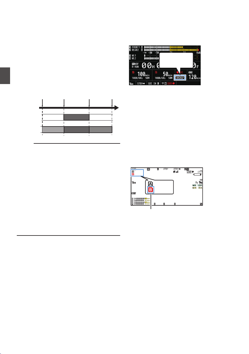
Backup Rec 0
0
The Backup Rec mode allows you to make use
of the media in slot B for backup recording by
controlling
the starting and stopping of recording
in slot B without using the [REC] button.
0
Start or stop the recording using [System] B
[Record Set] B [Slot Mode] B [Backup Rec] or
press the user button that is assigned with
“Backup Trig”.
(A P155
[ Slot Mode ] )
(A P111 [User Switch Set Item] )
.
Slot B
Slot A
Clip 3
Clip 2
Clip 1
Clip 2
Slot B stops
recording
Slot A stops
recording
Slot A starts
recording
Slot B starts
recording
Memo :
0
During the Backup Rec mode (when [Slot
Mode] is set to “Backup”), you can control
recording to the 2 slots at different timings, and
backup recording can only be performed on this
camera recorder.
(A P
155 [ Slot Mode ] )
0
You can record without worrying about missing
the important scenes by setting slot B to be
always recording (backup recording) and using
the [REC] button to start/stop recording of only
the required scenes in slot A.
0
It is recommended to use a media with high
capacity in slot B.
0
Backup cannot be selected when [WFormat] is
configured to “Exchange” (U model) or “MP4” (E
model).
1
Set [System]
B [Record Set] B [Slot Mode]
to “Backup”.
(A P
155 [ Slot Mode ] )
“BACKUP” appears on the enlarged display
screen.
.
BACKUP
2
Start backup recording. (Backup recording
into slot B)
0
Select “REC” in [System] B [Record Set] B
[Slot Mode] B [Backup Rec
] and press the
Set button (R).
(A P155
[ Slot Mode ] )
0
You can also press the user button that is
assigned with “Backup Trig”.
(A P111 [User Switch Set Item] )
0
Backup recording into slot B starts.
0
The card slot mark of slot B turns red
(selected state), and the status indicator of
slot B also blinks in red.
.
100min
50min
282min
1
/60
F2. 8
AE
±0
ND1
/64
12 :34 : 56
ISO
102400
00: 00:00.00
1080 /30p
SDI IN
ITU709
COMPRESS
5 . 6 f t
B 5600
K
50min
100min
Red (selected)
88
Backup Rec 0
Shooting
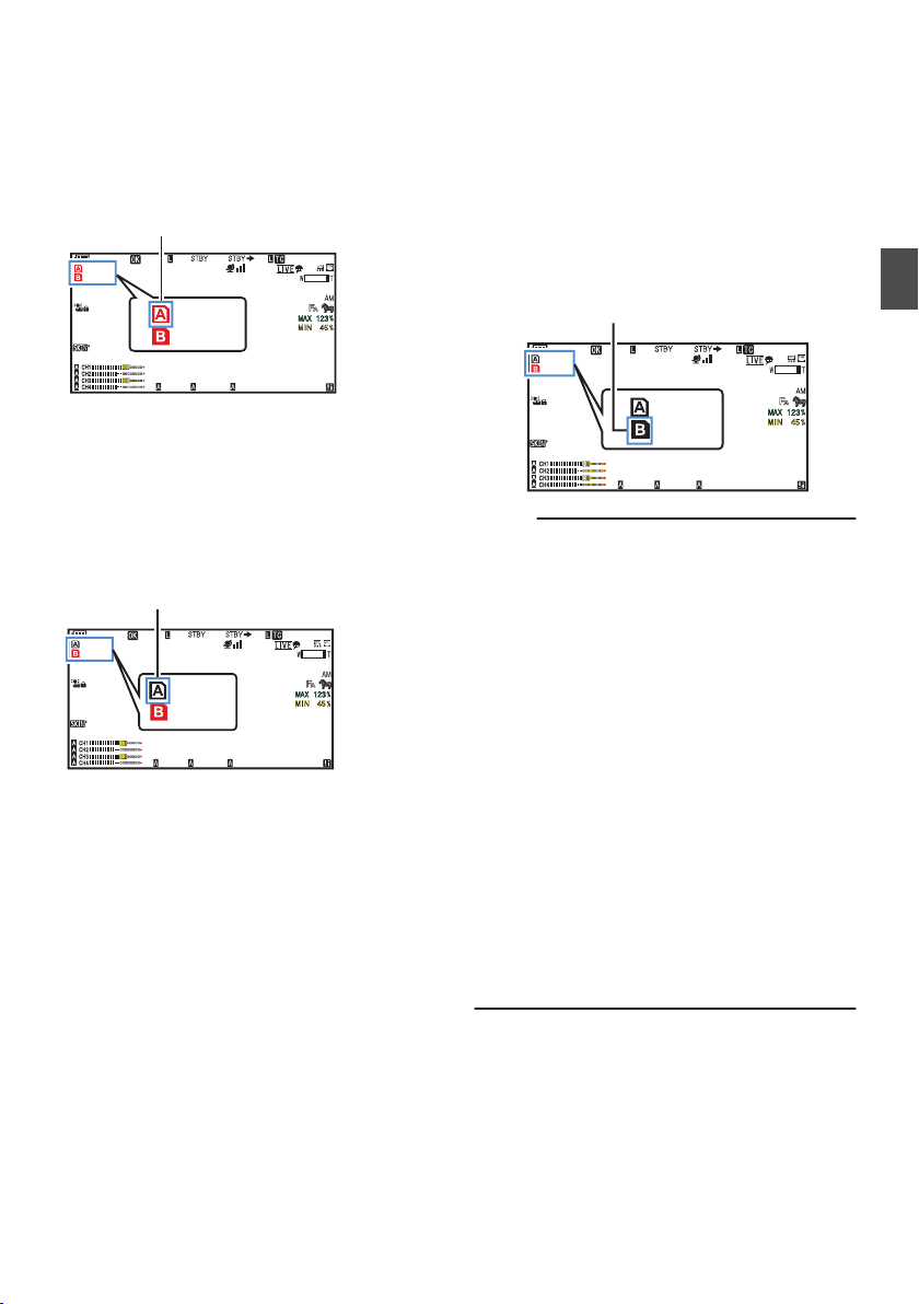
3
Start normal recording (normal recording
into slot A)
0
Press any of the [REC] buttons.
0
Recording into the media in slot A starts.
(The characters “RREC” appear in red.)
0
The card icon of slot A turns red (unselected
state), and the status indicator of slot A blinks
in red.
.
100min
50min
282min
1
/60
F2. 8
AE
±0
ND1
/64
12 :34 : 56
ISO
102400
00: 00:00.00
1080 /30p
SDI IN
ITU709
COMPRESS
5 . 6 f t
B 5600
K
50min
100min
Red (not selected)
4
Stop normal recording.
0
Press any of the
[REC] buttons again.
0
Recording to slot A stops, and the card slot
mark of slot A turns white (unselected state).
0
The characters “RREC” (red) changes back
to “STBY” (white).
0
The status indicator of slot A goes out.
.
100min
50min
282min
1
/60
F2. 8
AE
±0
ND1
/64
12 :34 : 56
ISO
102400
00: 00:00.00
1080 /30p
SDI IN
ITU709
COMPRESS
5 . 6 f t
B 5600
K
50min
100min
White (not selected)
5
Stop backup recording.
0
Select [STBY] in [System] B [Record Set] B
[Slot Mode] B [Backup Rec] and press the
Set button (R).
(A P155
[ Slot Mode ] )
0
You can also press the user button that is
assigned with “Backup Trig”.
(A P111 [User Switch Set Item] )
0
Recording to slot B stops, and the card slot
mark of slot B turns white (unselected state).
0
The status indicator of slot B lights up in
green.
.
100min
50min
282min
1
/60
F2. 8
AE
±0
ND1
/64
12 :34 : 56
ISO
102400
00: 00: 00.00
1080 /30p
SDI IN
ITU709
COMPRESS
5 . 6 f t
B 5600
K
50min
100min
White
Memo :
0
During backup recording, if the space of one
card runs out, recording stops only for the card
that is full.
0
When recording to both slots is stopped,
recording in the REGEN mode will be enabled
for the card slot in which recording started.
0
When recording is started in the other slot while
recording to one slot, the clip being recorded is
split and simultaneous recording to the other
card starts.
0
When recording is stopped for either slot A or B
while recording to both slots, the clip on the slot
which is still recording is split.
0
Although the clips are separated during
recording the clips can be seamlessly joined by
arranging them on the timeline of the editing
software since they are recorded seamlessly.
0
Clip Cutter Trig cannot be performed during
backup recording.
(A P94 [Splitting the Clips Freely (Clip Cutter
Trig) 0] )
0
When [Slot Mode] is set to “Backup”, [Rec
Mode] can only be set to “Normal”.
(A P
154 [ Rec Mode 0 1 ] )
Backup Rec 0
89
Shooting

Special Recording 0
Besides the normal recording mode, four special
recording methods are available in this camera
recorder. They are Pre Rec, Clip Continuous,
Frame Rec and Interval Rec.
Select a mode from [
System] B [Record Set] B
[Rec Mode].
(A P154 [ Rec Mode 0 1 ] )
Memo :
0
Special recording cannot be selected when
[System]
B
[Record Set]
B
[Record Format]
B
[System] is set to “HD+Web”
2
or “High-
Speed”
2
.
Pre Rec 0
0
By setting the number of seconds in the [Pre Rec
Time], you can start recording video and audio
before actual recording starts based on the [Pre
Rec Time] setting.
0
When
starting actual recording while the camera
recorder is in Recording Standby (STBYP)
mode, you can start recording a few seconds
earlier based on the [Pre Rec Time] setting.
0
Using Pre Rec allows you to record a complete
event without missing the initial scenes even if
you start the recording late.
Memo :
0
Pre Rec Time can be set in [System] B [Record
Set] B [Rec Mode] B [Pre Rec Time].
.
(Recording stops)
Press [REC]
(Recording starts)
Press [REC]
Recording starts a
number of seconds
earlier based on the
[Pre Rec Time] setting
(Recorded video and audio)
Completed Clip
1
Set [Rec Mode] to “Pre Rec”.
(A P154 [ Rec Mode 0 1 ] )
0
Set [System] B [Record Set] B [Rec Mode]
to “Pre Rec”.
0
The display changes (
“STBY” B “STBYP”).
2
Press the [REC] button to start recording in
Pre Rec mode.
0
The display changes (“STBYP” B
“RRECP”) and the card slot status indicator
lights up in red.
0
Press the [REC] button again to pause
recording. The display changes (“RRECP”
B “STBYP”) and the card slot status
indicator lights up in green.
Caution :
0
When the interval between start and stop
recording is short, “STBYP” may not be
displayed immediately after recording is
complete.
“RRECP” B “STBYP” (“STBY” blinks in red) B
“STBYP” is displayed.
0
When the SD card becomes full during
recording, recording stops and “STOP” is
displayed.
0
In the following cases, video and audio before
the specified Pre Rec time may not be recorded
even if recording starts.
0
Immediately after power on
0
Immediately after recording stops
0
Immediately after switching from Media
mode to Camera mode
0
Immediately after setting [Rec Mode]
0
Immediately after the end of Clip Review
0
Immediately after changing file format
0
Immediately after changing video format
90
Special Recording 0
Shooting
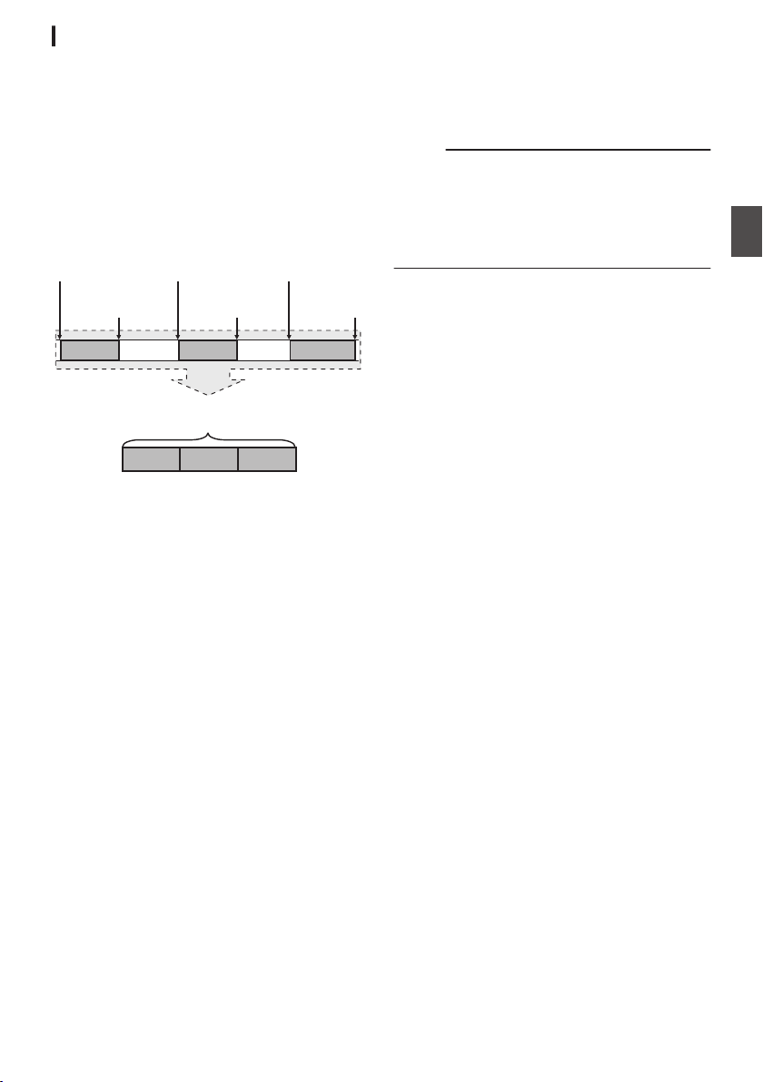
Clip Continuous Rec 0
0
In normal recording, when the recording stops,
the image, audio, and accompanying data from
the start till the end of the recording are recorded
as one “clip” on the SD card.
0
This mode allows you to consolidate several
rounds of “startstop recording” into one clip.
Example:
In normal recording, three clips are generated as
Recording 1, Recording 2, and Recording 3.
However, recording in this mode generates only
one clip.
.
(Recorded video and audio)
Completed Clip
Recording 3
Recording 2
Recording 1
Recording 3
Recording 2
Recording 1
(Recording stops)
Press and hold [REC]
(Recording pauses)
Press [REC]
(Recording pauses)
Press [REC]
(Recording resumes)
Press [REC]
(Recording resumes)
Press [REC]
(Recording starts)
Press [REC]
1
Set “Rec Mode” to “Clip Continuous”.
(A P154 [ Rec Mode 0 1 ] )
0
Set [System] B [Record Set] B [Rec Mode]
to “Clip Continuous”.
0
The display changes (
“STBY” B “STBYC”).
2
Start recording. (Recording 1)
0
Press the [REC] button to start recording in
Clip Continuous mode.
0
The display changes (“STBYC” B
“RRECC”) and the card slot status indicator
lights up in red.
3
Pause recording.
0
Press the [REC] button again to pause
recording. The display changes (“RRECC”
B “STBYC” (yellow text)).
0
The
card slot status indicator remains lighted
in red.
Memo :
0
When the [CANCEL/RESET] button is pressed
while the camera recorder is paused (STBYC),
the display changes (“STBYC” (yellow text) B
“STBYC” (blinking yellow text) B “STBYC”
(white text)), and a “clip” is generated. The card
slot status indicator lights up in green.
4
Resume recording. (Recording 2)
0
Press the [REC] button again to resume
recording. The display changes (“STBYC”
(yellow text) B “RRECC”).
0
The card slot status indicator remains lighted
in red.
5
Pause recording.
0
Press the [REC] button again to pause
recording. The display changes (“RRECC”
B “STBYC” (yellow text)).
0
The card slot status indicator remains lighted
in red.
6
Resume recording. (Recording 3)
0
Press the [REC] button again to resume
recording. The display changes (“STBYC”
(yellow text) B “RRECC”).
0
The card slot status indicator remains lighted
in red.
7
Press and hold the [REC] button.
0
Recording stops and the display changes
(“RRECC” B “STBYC”). A “clip” is
generated.
0
The card slot status indicator lights up in
green.
8
Press the [REC] button again.
0
The display changes (“STBYC” B
“RRECC”) and the card slot status indicator
lights up in red.
0
A new “clip” is generated from here.
Special Recording 0
91
Shooting
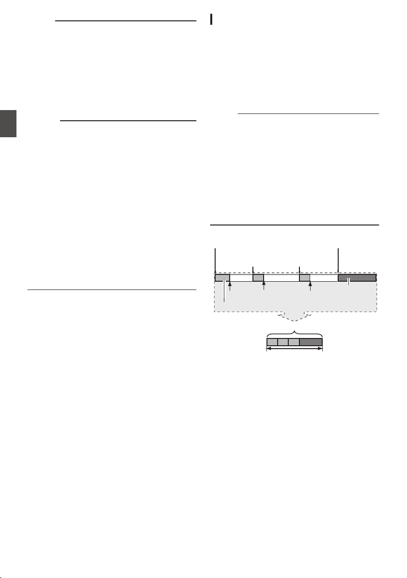
Memo :
0
The following operations cannot be performed
while recording is paused (STBYC, yellow text).
0
Clip Review operation
(A P84 [Viewing Recorded Videos
Immediately (Clip Review)] )
0
Switching SD card slots
0
Switching operation mode
(A P20 [Operation Modes] )
0
Files are split into sizes of 4 GB (or 30 minutes)
regardless of the menu settings.
Caution :
0
Do not remove the SD card during recording
(RRECC, red text) or recording pause
(STBYC, yellow text).
0
To remove the SD card in the “Clip
Continuous” mode, press the [CANCEL/
RESET] button, check that “STBYC” (white
text) is displayed and the card slot status
indicator lights up in green before you remove
the card.
0
When the SD card becomes full during
recording, recording stops and
“STOP” is
displayed.
0
When the [POWER ON/OFF] switch is turned off
during recording or recording pause, recording
stops and power is cut off after a clip is
generated.
0
If the power is cut off due to low battery power,
a proper clip may not be generated.
Frame Rec 1
In normal recording, when the recording stops, the
image and accompanying data from the start till the
end of the recording are recorded as one “clip” on
the SD card.
In this mode, recording starts with every press of
the [REC] button, and only the specified number of
frames is recorded.
The recording can be written to the media as a
single clip until it is stopped.
Memo :
0
Audio will not be recorded.
0
Until a specified amount of recordings is
accumulated, the file cannot be written to the
media.
0
If the specified amount is not reached when
recording is stopped, normal recording is
performed and frames are added to the ending
of the clip until the amount is reached. (Padding)
0
After the specified number of frames is recorded
and written to the media, recording will be
performed until the same number is
accumulated again.
.
Specific amount of data
Actual clips recorded to the media
Records number of frames specified in [Rec Frames]
(Padding data)
Normal recording
PausePausePause
Recording resumes
Recording resumes
Press [REC]Press [REC]
(Frame Rec stops)(Frame Rec starts)
Press and hold [REC]Press [REC]
1
Set [Rec Mode] to “Frame Rec”.
0
Set [System] B [Record Set] B [Rec Mode]
to “Frame Rec”.
(A P
154 [ Rec Mode 0 1 ] )
0
The display changes (“STBY” B “STBYM”).
92
Special Recording 0
Shooting
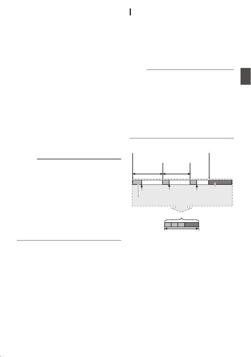
2
Set the number of frames to record in [Rec
Frames].
0
To configure the setting, go to
[System] B
[Record Set] B [Rec Mode] B [Rec Frames].
(A P
154 [ Rec Frames 1 ] )
3
Start recording.
0
Press the [REC] button to record only the
number of frames specified in [Rec Frames]
and pause.
0
The display changes (“STBYM” B “RRECM”
B “STBYM” (yellow text)).
0
The card slot status indicator lights up in
green.
4
Repeat Frame Rec.
0
Press the [REC] button again to record only
the number of frames specified in [Rec
Frames] and pause.
0
The display changes (“STBYM” B “RRECM”
B “STBYM” (yellow text)).
0
Frame Rec continues until the recording is
stopped (step 5).
5
Press and hold the [REC] button.
0
The card slot status indicator lights up in
green.
Caution :
0
Do not remove the SD card during recording
(“RRECM”, red text) or recording pause
(“STBYM”, yellow text).
0
To remove the SD card during Frame Rec, press
the [CANCEL/RESET] button, check that
“STBYM” (white text) is displayed and the card
slot status indicator lights up in green before you
remove the card.
0
When the [TC GEN] selection switch is set to “F-
RUN”, the time code will be recorded in “R-
RUN”.
0
Audio cannot be recorded. The audio level
meter is grayed out.
(A P162 [Audio Level Meter] )
Interval Rec 1
In normal recording, when the recording stops, the
image and accompanying data from the start till the
end of the recording are recorded as one “clip” on
the SD card.
In this mode, recording and pause are performed
repeatedly at the specified time interval. Only the
specified number of frames is recorded.
The recording can be written to the media as a
single clip until it is stopped.
Memo :
0
Audio will not be recorded.
0
Until a specified amount of recordings is
accumulated, the file will not be written to the
media.
0
After the specified number of frames is recorded
and written to the media, recording will be
performed until the same number is
accumulated again.
0
If the specified amount is not reached when
recording is stopped, normal recording is
performed and frames are added to the ending
of the clip until the amount is reached. (Padding)
.
Specific amount of data
Actual clips recorded to the media
Records number of frames specified in [Rec Frames]
(Padding data)
Normal recording
PausePausePause
[Rec Interval][Rec Interval]
Recording resumes
Recording resumes
(Interval Rec stops)(Interval Rec starts)
Press [REC]Press [REC]
1
Set [Rec Mode] to “Interval Rec”.
0
Set [System] B [Record Set] B [Rec Mode]
to “Interval Rec”.
(A P
154 [ Rec Interval 1 ] )
0
The display changes (“STBY” B “STBYN”).
2
Set the number of frames to record in [Rec
Frames].
To configure the setting, go to [System] B
[
Record Set] B [Rec Mode] B [Rec Frames].
(A P154 [ Rec Frames 1 ] )
Special Recording 0
93
Shooting
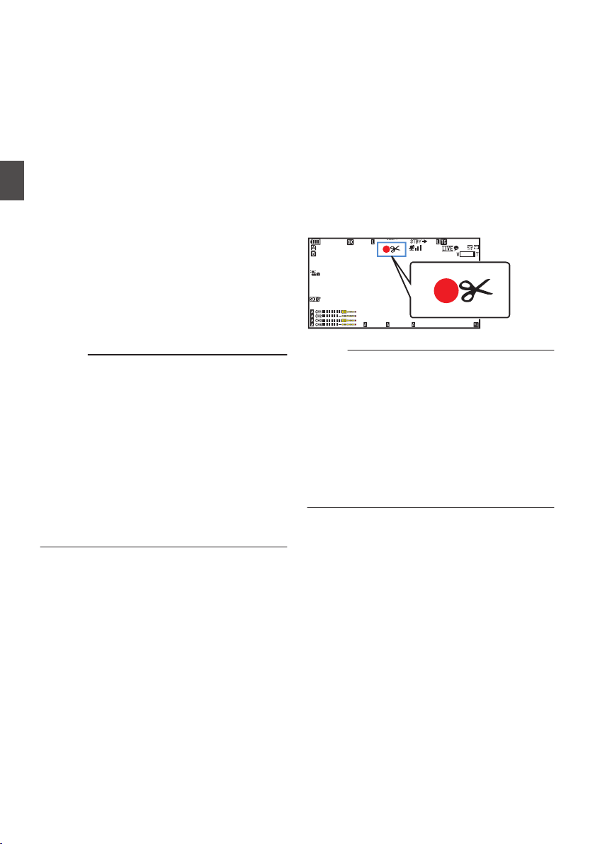
3
Set the time interval to start recording in
[Interval Rec].
To configure the setting, go to [System] B
[Record Set] B [Rec Mode] B [Rec Interval].
(A P154 [ Rec Interval 1 ] )
4
Start recording.
0
Press the [REC] button to record only the
number of frames specified in [Rec Frames]
and pause.
0
After the specified time in [Rec Interval] has
passed,
recording starts again to record only
the number of frames specified in [Rec
Frames] and pause.
0
Interval Rec continues until the recording is
stopped.
The display changes (“STBYN” B “RRECN”
B “STBYN” (red text) B “RRECN” B
“STBYN” (red text)).
0
The
card slot status indicator lights up in red.
5
Press the [REC] button.
0
The card slot status indicator lights up in
green.
0
The display becomes “STBYN”.
Caution :
0
Do not remove the SD card during recording
(RRECN, red text) or recording pause (STBYN,
yellow text).
0
To remove the SD card during Interval Rec,
press the [CANCEL/RESET] button, check that
“STBYN” (white text) is displayed and the card
slot status indicator lights up in green before you
remove the card.
0
When the [TC GEN] selection switch is set to “F-
RUN”, the time code will be recorded in “R-
RUN”.
0
Audio cannot be recorded. The audio level
meter is grayed out.
(A P162 [Audio Level Meter] )
Splitting the Clips Freely
(Clip Cutter Trig) 0
You can split the clips freely without having to stop
recording during shooting.
1
Assign the “Clip Cutter Trig” function to
any of the user buttons.
(A P
45 [Assignment of Functions to User
Buttons] )
2
Press the user button that is assigned with
“Clip Cutter Trig” during shooting.
A clip cut icon (Q) appears on the display
screen for 3 seconds, and the clip is split.
.
100min
50min
282min
1
/60
F2. 8
AE
±0
ND1
/64
12 :34 : 56
ISO
102400
00: 00:00.00
1080 /30p
SDI IN
ITU709
COMPRESS
5 . 6 f t
B 5600
K
Memo :
0
Clips cannot be split again for a few seconds
after the operation is performed.
0
This item cannot be used when [Slot Mode] is
set to “Backup”.
0
This item cannot be used when
[Rec Mode] is
set to a value other than “Normal” or “Pre Rec”.
(A P154
[ Rec Mode 0 1 ] )
0
The split clips are recorded seamlessly without
interruptions in the video.
0
When Exchange
(U model) or MP4 (E model) is
selected, the clip cutter function cannot be used.
94
Special Recording 0
Shooting
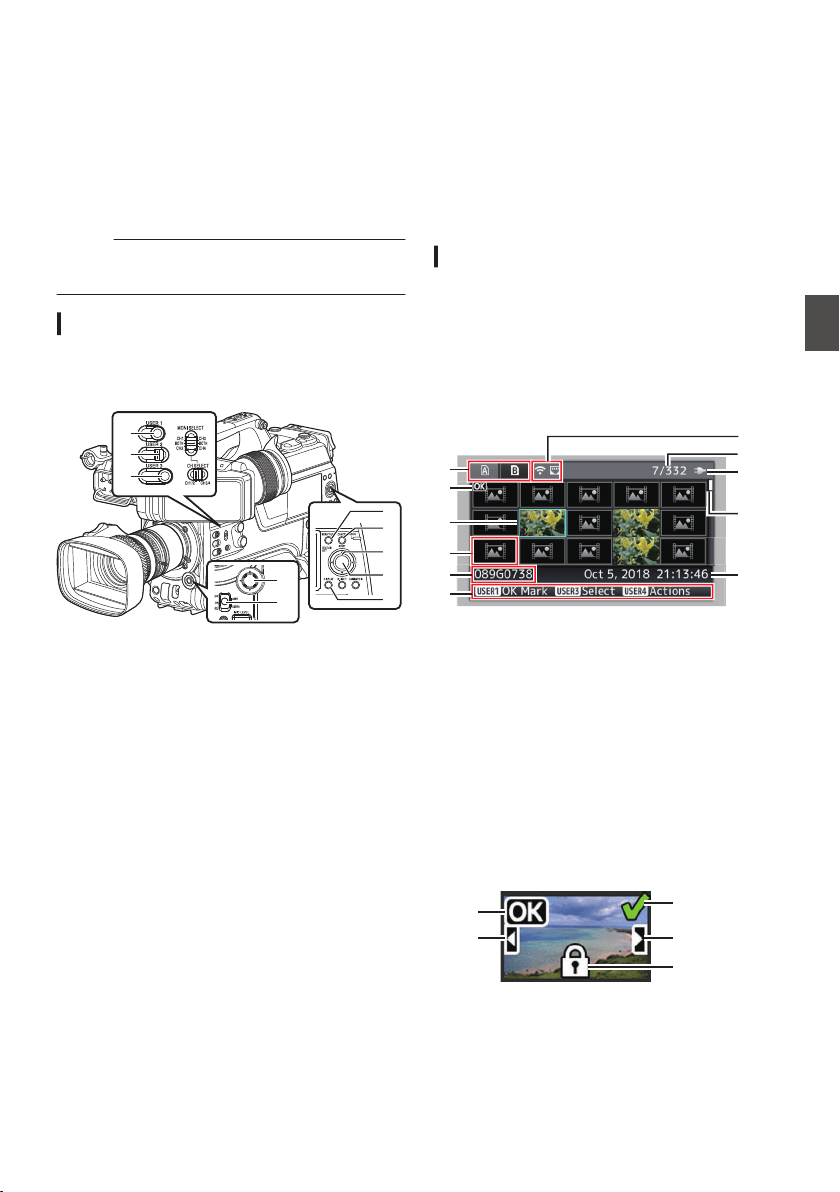
Playing Recorded Clips
To play back clips recorded on SD cards, switch to
the Media mode.
Press and hold the [CAM/MEDIA] selection button
in the Camera mode to enter the Media mode. A
thumbnail screen of the clips recorded on the SD
card is displayed.
You can play back the selected clip on the
thumbnail screen.
Memo :
0
When an SD card without any clips is inserted,
“No Clips
” is displayed.
Operation Buttons
Use the operation buttons on the side control panel
or front side of the camera recorder to operate the
thumbnail screen.
.
D
A
B
H
C
B
C
E
G
F
A
[MENU/THUMB] Button
0
Displays the menu.
0
Press this button to close the menu screen
during menu display and return to the
thumbnail screen.
B
Cross-Shaped Button (JKHI)
Moves the cursor.
C
[STATUS/SET] (Play) Button
0
Sets the values and items. (Confirm)
0
Plays back the selected clip.
D
[CANCEL/RESET] (Stop) Button
Cancels settings and returns to the previous
screen.
E
[USER1] Button
0
Switches the OK mark of the clip selected by
the cursor.
0
If an OK mark has been appended, it will be
deleted. Otherwise, an OK mark will be
appended.
F
[USER3] Button
0
Switches the selection status of the clip
selected by the cursor.
0
Clips being selected are displayed with
check mark.
G
[USER4] Button
Enters the action selection screen.
H
[DISPLAY] Button
Switches to “Standard Screen”, “Detailed
Screen” or “Media Information Screen”.
Thumbnail Screen
0
“Standard Screen” and “Detailed Screen” are
available.
Use the [DISPLAY] button to switch between the
screens.
0
Thumbnails are displayed in order of recording
from the oldest to most recent.
Standard screen
.
A
J
H
C
B
G
E
D
F
I
K
A
SD Card Information
0
Displays the status of the inserted SD card,
selected SD card, write-protect switch, and
the need for restoring.
0
Use the [SLOT A/B] switch to switch slots.
Clips in slot A and B cannot be displayed at
the same time.
W z
:
Write-protect switch of the SD card
in slot A is set.
S
:
SD card in slot B needs to be
restored or formatted, or is an
unsupported SD card.
B
Clip Mark
Displays the clip information (properties).
.
A
B
D
E
C
A
OK Mark
Clip is appended with OK mark.
Playing Recorded Clips
95
Playback

Memo :
0
Clips appended with OK marks cannot be
deleted on the camera recorder.
B
Continued From Mark
This mark indicates that the current clip is
continued from another SD card when
recording is divided and made on several SD
cards.
C
Uneditable Mark
0
This mark indicates that an OK mark cannot
be
appended to or deleted from the clip, and
the clip cannot be deleted.
D
Continue Mark
This mark indicates that recording of the current
clip is continued to another SD card when
recording is divided and made on several SD
cards.
E
Check Mark
0
A green check mark is displayed when the
clip is selected.
0
Magenta and gray check marks are
displayed in multiple selection mode.
(A
P102 [Selecting and Performing
Operations on Multiple Clips] )
C
Cursor
Clip to be worked on. Use the cross-shaped
button (JKHI) to move the cursor.
D
Thumbnail Substitution Display
.
A B
A
A clip with corrupted management information.
It cannot be played back even if you press the
Set (Play) button.
B
A clip that cannot be played back nor displayed
in thumbnail with the current video format
settings.
It cannot be played back even if you press the
Set (Play) button.
Memo :
0
Dependent on the settings for [System] B
[Record Set] B [Record Format] B [System]/
[WResolution]/[YResolution]/[WFrame Rate]/
[YFrame Rate]/[WBit Rate], and [YBit Rate].
(A P151
[ System ] )
(A P152 [ W Resolution ] )
(A P152 [ W Frame Rate ] )
(A P153 [ W Bit Rate ] )
E
Clip Name
The file name (clip number) of the selected clip
is displayed.
F
Operation Guide
0
Displays a guide for the current operation
buttons.
0
The action selection screen is displayed
when the [USER4] button is pressed.
(A P97 [Actions] )
G
Recording Start Time
Displays the recording start time of the clip.
Memo :
0
The date/time display is dependent on the
settings in [System] B [Date Style]/[Time Style].
(A P150 [ Date Style ] )
(A P150 [ Time Style ] )
H
Scroll Bar
0
Indicates the scroll position.
0
Black space below the scroll bar (white)
indicates that there are more pages.
0
When the scroll bar (white) is at the bottom,
this indicates the last page.
I
Remaining Battery Power
(A P36
[Power Status Display] )
J
Number of Clips
0
If none of the clips are selected, the “running
number/total number of clips” of the clip to be
displayed appears.
0
Even if only one clip is selected, the number
of selected clips in the current slot is
displayed.
K
Network Connection Icon
0
The network connection status is displayed.
96
Playing Recorded Clips
Playback
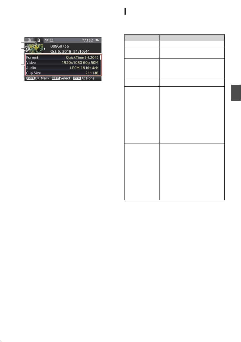
Detailed screen
* Items that are common with the Standard screen
will not be described. Refer to “[Standard
screen] (A P 95)”.
.
C
B
A
A
Thumbnail
Thumbnail of the clip selected by the cursor.
Use the cross-shaped button (HI) to move the
cursor.
B
Scroll Mark (DE)
0
If there are previous clips, D appears on the
left.
0
If there are more clips, E appears on the right.
0
The marks will not be displayed if there are
no clips before and after the current clip.
C
Metadata
Metadata of the clip pointed by the cursor.
You can use the cross-shaped button (JK) to
scroll.
Actions
The action selection screen is displayed when the
[USER4] button is pressed.
The following operations can be performed.
Item Description
Select All Clips Selects all clips.
Select OK
Marked
Selects all clips appended with
OK mark.
Select Range Specifies the range when
selecting multiple clips.
(A P
102 [Selecting Multiple
Clips Randomly] )
Deselect All Clears all clip selections.
Add OK Mark Appends an OK mark.
0
This Clip:
Appends an OK mark to the
clip pointed by the cursor.
0
Selected Clips:
Appends an OK mark to the
clips selected (appended
with check mark).
0
All Clips:
Appends an OK mark to all
clips.
Delete OK Mark Deletes the OK mark.
0
This Clip:
Deletes the OK mark of the
clip pointed by the cursor.
0
Selected Clips:
Deletes the OK mark of the
clips selected (appended
with check mark).
0
All Clips:
Deletes the OK mark of all
clips.
Playing Recorded Clips
97
Playback
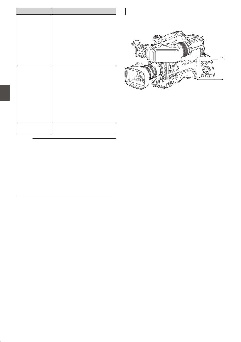
Item Description
FTP Upload Uploads a clip to the FTP server.
0
This Clip:
Uploads the clip pointed by
the cursor.
0
Selected Clips:
Uploads the clips selected
(appended with check
mark).
0
All Clips:
Uploads all clips.
Delete Clips Deletes clip. However, clips with
OK mark cannot be deleted.
0
This Clip:
Deletes the clip pointed by
the cursor.
0
Selected Clips:
Deletes the clips selected
(appended with check
mark).
0
All Clips:
Deletes all clips.
Trim This Clip Trims the clip pointed by the
cursor.
Memo :
0
The object of action is the clip of the current slot
being displayed.
0
[Selected Clips] cannot be performed if there are
no selected (appended with check mark) clips.
0
[This Clip] cannot be performed if there are more
than one selected (appended with check mark)
clips.
0
If the write-protect switch of an SD card is set,
OK mark cannot be appended or deleted, and
the clips cannot be deleted and trimmed.
Playing back
Use the operation buttons on the side control panel
of the camera recorder to play back.
.
C
B
A
A
[STATUS/SET] Button (R)
0
Plays back/pauses the clip pointed by the
cursor.
0
You can press the cross-shaped button (HI)
to perform frame-by-frame forward playback
during pause mode.
B
Cross-shaped Button (JKH I)
0
[J/K] Button:
Skips in the reverse or forward direction.
0
[H/I] Button:
0
During Playback:
Fast forwards in the reverse or forward
direction.
0
While paused:
Frame-by-frame playback in the reverse
or forward direction.
C
[
CANCEL/RESET] Button
Stops playback.
1
In the thumbnail screen, move the cursor to
the clip to be played back.
Move the cursor to the clip to be played back
using the cross-shaped button (JKH I).
2
Press the [STATUS/SET] button (
R).
Playback of the selected clip starts.
Audio Output during Playback
0
You can confirm the playback sound from the
monitor speaker, or the headphone connected
to
the [PHONE] terminal. When a headphone is
connected to the [PHONE] terminal, sound
cannot be output from the monitor speaker.
(A P
181 [Connecting the Headphone] )
0
Adjust the volume of the monitor speaker or
headphone using the [MONITOR] volume
adjustment knob.
98
Playing Recorded Clips
Playback
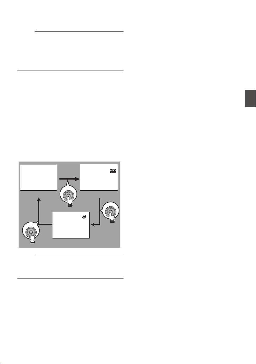
Time Code Playback
Time code or user’s bit recorded on an SD card can
be displayed on the LCD monitor and viewfinder.
Memo :
0
The time code is also superimposed on the
video signal output from the
[HD/SD SDI OUT
1/2] terminal.
0
If
a section without time code is played back, the
time code will stop. However, playback will
continue.
Displaying Information during Shooting
Pressing the [DISPLAY] button during playback
displays the display screen.
Pressing the [USER4] button during shooting
switches the display information between camera
information display, GPS display and turning off the
display.
0
The GPS display displays information on the
recording location of the video being played
back only when GPS information has been
recorded.
0
Camera information display displays only
information of Gain, Iris, Shutter and White
Balance that have been recorded.
.
5600K
1/100
F1. 6
0
dB
+35.483197
+139.652172
USER4
USER4
USER4
GPS Display
Camera Information Display
Display Off
Memo :
0
Trimming information is displayed while
trimming is in progress. In this case, pressing the
[USER4] button does not switch the display.
Playing Recorded Clips
99
Playback
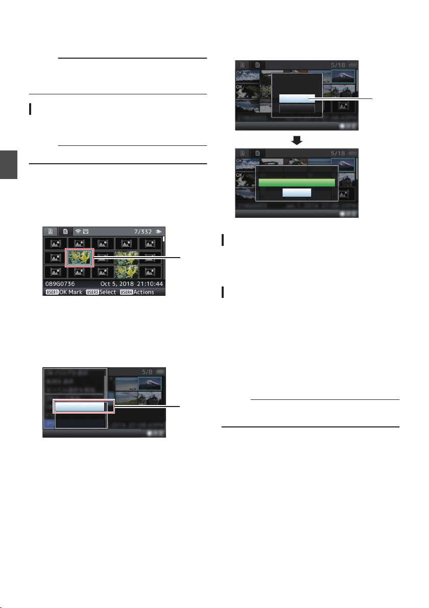
Deleting Clips
Delete clip.
Memo :
0
Clips appended with OK marks cannot be
deleted on the camera recorder.
0
Read-only clips can be deleted on a PC.
Deleting One Clip
Delete the clip (one clip) pointed by the cursor in
[Delete Clips] B [This Clip] in the menu.
Memo :
0
Clips with OK mark cannot be deleted.
During Thumbnail Screen
1
Move the cursor to the clip to be deleted.
Move the cursor to the clip to be deleted using
the cross-shaped button (JKH I).
.
1
2
Press the [USER4] button.
The action selection screen is displayed.
3
Select [Delete Clips]
B [This Clip] and press
the Set button (
R).
A screen to confirm deletion appears.
.
3
All Clips
Selected Clips
This Clip
4
Select [Delete] using the cross-shaped
button (
JK), and press the Set button (R).
Deleting starts.
.
4
Stop
Deleting...
Cancel
Delete
Delete This Clip?
Selecting and Deleting Multiple Clips
To select and delete multiple clips, refer to
“[Selecting and Performing Operations on Multiple
Clips] (A P 102)”.
Deleting All Clips
Delete all clips that are displayed.
1
Press the [USER4] button.
The action selection screen is displayed.
2
Select [Delete Clips]
B [All Clips].
A screen to confirm deletion appears.
3
Select [Delete] and press the Set button
(
R).
Deleting starts.
Memo :
0
The time taken to delete clips depends on the
number of clips to be deleted.
100
Deleting Clips
Playback
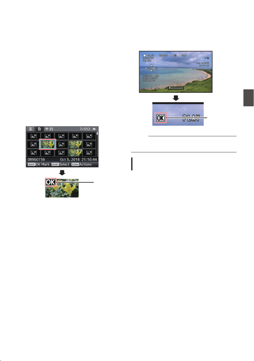
Appending/Deleting OK
Mark
0
You can append OK marks to the clips for
important scenes.
0
Clips appended with OK marks cannot be
deleted, thus protecting the important clips.
0
When the camera recorder is in Media mode,
you can delete the OK marks appended during
recording, or append/delete OK marks after
shooting.
During Thumbnail Screen
1
Press the [USER1] button.
0
If the clip does not have an OK mark, an OK
mark will be appended.
0
If the clip is appended with an OK mark, the
OK mark will be deleted.
.
OK Mark
During Playback or Pause Screen
1
Press [USER1
] button during clip playback.
0
If the clip does not have an OK mark, an OK
mark will be appended.
0
If the clip is appended with an OK mark, the
OK mark will be deleted.
.
OK Mark
Memo :
0
The clip pauses when an OK mark is appended
or deleted during playback.
Appending/Deleting OK Mark of
Multiple Clips
To select and append/delete OK mark for multiple
clips, refer to “[Selecting and Performing
Operations on Multiple Clips] (A P
102)”.
Appending/Deleting OK Mark
101
Playback
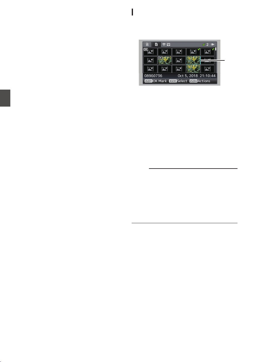
Selecting and Performing
Operations on Multiple
Clips
0
Multiple clips can be selected during thumbnail
screen or playback screen display.
0
After selecting multiple clips, perform
appending/deleting
of OK mark, deleting of clips
using the action selection screen.
0
After selecting multiple clips, the selections will
be canceled by the following operations.
0
When [Deselect All] in the action menu is
selected
0
When exiting Media mode from the thumbnail
screen
0
When removing the SD card
0
When switching the slot in use
Selecting Multiple Clips Randomly
1
Move the cursor to a clip without a check
mark, and press the [USER3] button.
A green check mark appears on the clip.
.
1
2
Repeat Step
1 to select multiple clips.
0
Multiple clips can be selected.
0
Press the [USER4] button while the multiple
clips are selected.
0
Appends OK mark together:
[Add OK Mark] B [Selected Clips]
0
Deletes OK mark together:
[Delete OK Mark]
B [Selected Clips]
0
Uploading selected clips to the FTP server
together:
[FTP Upload] B [Selected Clips]
0
Deletes selected clips together:
[Delete Clips] B [Selected Clips]
Memo :
0
Selecting clips appended with check mark and
pressing the [USER3] button will cancel the
selection.
0
If the operation is performed on multiple clips at
the same time, a progress bar appears. You can
stop the operation by pressing the Set button (R)
while the operation is in progress. However, it is
not possible to undo operations that are
completed.
102
Selecting and Performing Operations on Multiple Clips
Playback
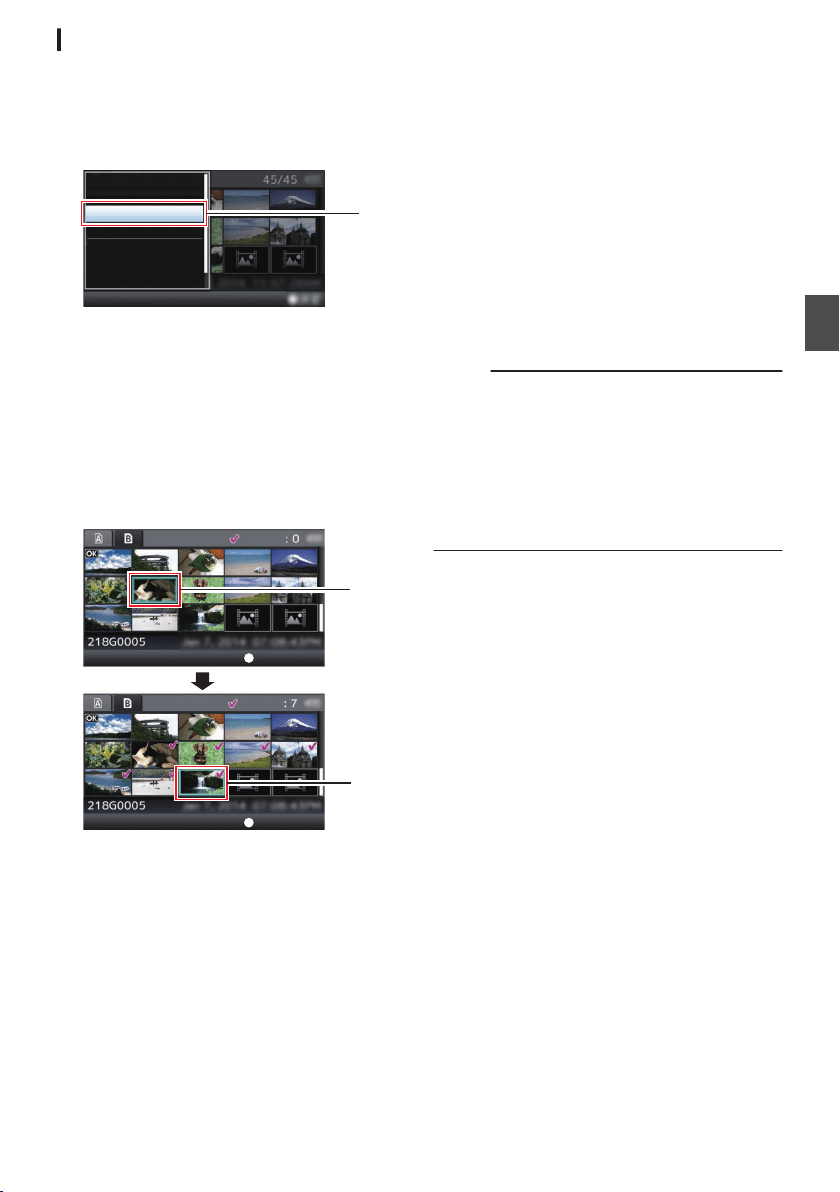
Selecting Multiple Clips Consecutively
1
Press the [USER4] button.
2
Select “Select Range” in the action
selection screen, and press the Set button
(
R).
.
FTP Upload...
Delete OK Mark...
Add OK Mark...
Deselect All
Select Range
Select OK Marked
Select All Clips
2
3
Move the cursor to the beginning (or end)
of the range for multiple selection, and
press the Set button (
R).
4
Move the cursor to the other end of the
range.
0
Magenta check marks appear on the clips
within the range. (Including clips that were
already selected.)
0
Gray check marks appear on selected clips
that are outside the range.
.
3
4
Selected Range:
Selected Range:
End Position
Start Position
5
Press the Set button (
R) to confirm the
range.
0
The check marks change from magenta to
green.
0
Pressing the [USER4] button while the
multiple clips are selected displays the action
selection screen. The following operations
can be performed.
0
Appends OK mark together:
[Add OK Mark] B [Selected Clips]
0
Deletes OK mark together:
[Delete OK Mark] B [Selected Clips]
0
Uploading selected clips to the FTP server
together:
[FTP Upload] B [Selected Clips]
0
Deletes selected clips together:
[Delete Clips] B [Selected Clips]
Memo :
0
Selecting clips appended with check mark and
pressing the [USER3] button will cancel the
selection.
0
If the
operation is performed on multiple clips at
the same time, a progress bar appears. You can
stop the operation by pressing the Set button (R)
while the operation is in progress. However, it is
not possible to undo operations that are
completed.
Selecting and Performing Operations on Multiple Clips
103
Playback
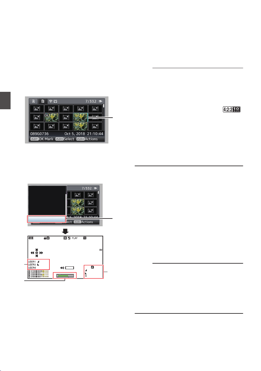
Trimming Recorded Clips
You can extract (trim) the necessary parts of a clip
recorded in the SD card.
The trimmed clip is saved as a new file on the same
SD card as the original clip. No changes are made
to the original clip.
1
Switch to Media mode.
Switch the mode using the [CAM/MEDIA]
selection button on the side control panel.
2
Move the cursor to the clip to be trimmed.
Move the cursor to the clip to be trimmed using
the cross-shaped button (JKH I).
.
2
3
Press the [USER4] button.
The action selection screen is displayed.
4
Select [Trim This Clip], and press the Set
button (
R).
Playback of the selected clip starts.
.
0
30min
11:22: 33.00
11:23: 44.00
00:08: 22
282min
12 :34 : 56
Jan 24,2018
00:00: 00.00
1920x1080
30p 50M
1000/ 2000
TRIM
OUT
IN
Trim This Clip
Delete Clips...
FTP Upload...
Delete OK Mark...
Add OK Mark...
Deselect All
Select Range
A
B
C
4
A
Guide
Operation guide
B
Position bar
6
: Current position of the video
7
: Position to start trimming (in point)
8
: Position to end trimming (out point)
C
Trimming information
W or Y : Indicates the available space in
the storage media (W or Y)
7
: Indicates the time code of the in
point
8
: Indicates the time code of the out
point
9
: Indicates the duration from the in
point to the out point
Memo :
0
The
trimmed
clip will be saved to the same card
slot as that of the original clip.
0
[Duration] appears in yellow if the duration is 10
minutes or longer. Trimming cannot be
performed in this case.
0
When [System] B [Record Set] B [Record
Format] B [WFrame Rate] is set to “
70M (XHQ)”2, [Duration] appears in
yellow if the duration is 6 minutes or longer.
Trimming cannot be performed in this case.
0
[Duration] appears in yellow if the duration is
longer than the recordable time on the storage
media. Trimming cannot be performed in this
case.
0
When trimming starts, the display switches to
the Media Display screen.
5
Specify the in point.
0
Operate
buttons such as H/I or J/K to move
the video to the in point.
(A P98 [Playing back] )
0
Specify the in point by pressing the [USER1]
button at the point you want to start trimming.
6
Specify the out point.
0
Operate buttons such as H/I or J/K to move
the video to the out point.
(A P98 [Playing back] )
0
Specify the out point by pressing the
[USER3] button at the point you want to end
trimming.
7
Perform trimming.
Press the [USER4] button to perform trimming.
Memo :
0
While trimming is in progress, you can press the
[CANCEL/RESET] button to return to the
thumbnail screen.
0
When trimming the in and out point, the in point
trimmed may be up to one second before the
specified in point and the out point trimmed may
be up to one second behind the specified out
point.
104
Trimming Recorded Clips
Playback
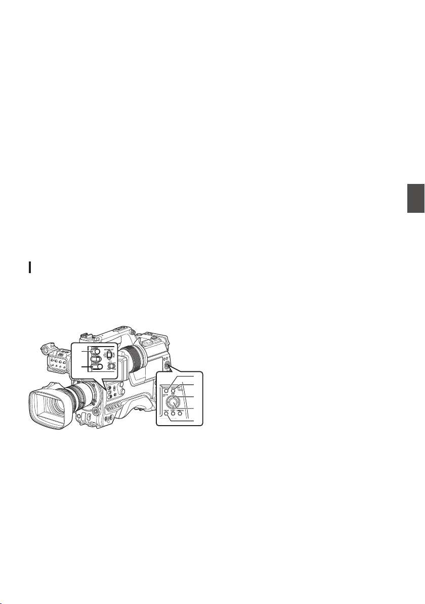
Basic Operations in Menu
Screen
0
Pressing the [MENU/THUMB] button displays
the menu screen on the LCD monitor and
viewfinder.
0
Various settings for shooting and playback can
be configured on the menu screen.
0
There are two types of menu screens -
[Main
Menu] and [Favorites Menu].
0
[Main Menu
] contains all the setting items of the
camera recorder, classified according to
functions and uses, while [Favorites Menu]
allows users to customize the menu items freely.
(A P
157 [Adding/Editing Frequently Used
Menu Items (Favorites Menu)] )
0
The operating procedures and main screen
displays are the same for both menus.
0
The menu screen can also be displayed on
external monitors connected to the video signal
output terminal.
(A P131 [ SDI OUT2 Char. ] )
(A P131 [ HDMI Char. ] )
(A P131 [ Video OUT Char. ] )
Operation Buttons
To operate the menu, use the cross-shaped
buttons on the side operation panel of the camera
recorder or the cross-shaped buttons at the front of
the camera or at the bottom of the lens.
.
D
C
E
G
F
A
B
A
[USER1] Button
Adds the selected menu or submenu item to the
[Favorites Menu].
B
[USER3] Button
Resets settings in the [TC Preset] or [UB
Preset] setting screen.
C
[MENU/THUMB] Button
0
Displays the menu screen. The
[Main
Menu] screen is displayed by default.
0
During normal usage, [Main Menu
] is
displayed if the previous menu operation
ended at [Main Menu], and [Favorites
Menu] if the previous menu operation ended
at [Favorites Menu].
0
Press this button to close the menu screen
during
menu display and return to the normal
screen.
0
Pressing and holding down the button while
the menu is displayed switches the [Main
Menu] screen to the [Favorites Menu] or vice
versa.
(A P
157 [Adding/Editing Frequently Used
Menu Items (Favorites Menu)] )
D
[CANCEL/RESET] Button
Cancels settings and returns to the previous
screen.
E
Cross-shaped Button (JKH I)
J
: Moves the cursor upward.
K
: Moves the cursor downward.
H
: Moves back to the previous item.
I
: Moves forward to the next item.
F
[STATUS/SET] Button (R)
Sets the values and items.
G
[DISPLAY] Button
Switches between the [Main Menu] and
[Favorites Menu] screens.
Basic Operations in Menu Screen
105
Menu Display and Detailed Settings

Display and Description of the Menu
Screen
Selecting Menu Items
.
AddFavorites
SECShutter
24hourTime Style
YMDDate Style
OnDate/Time
TimeBattery
OffAudio Meter
Display Settings
H
I
F
E
B
D
G
A
C
A
Cursor
Indicates the selected item. Use the cross-
shaped button (JK) to move the cursor
B
Menu Item
0
Displays the names of the menu item and
sub-menu.
0
Menu
items with [...] after them indicates that
there is a sub-menu to access.
C
Fixed Item
Items that cannot be changed are displayed in
gray and cannot be selected.
D
Operation Guide
Guide for the current operation buttons.
E
Setting Value
Setting values for the menu items.
For menus with sub-menus, values are not
displayed.
F
Scroll Bar
Indicates the scroll position.
G
Header
Indicates the current menu type with the line
color.
Blue
: [Main Menu] Screen
Green : [Favorites Menu] (Operation
screen)
Magenta : [Favorites Menu] (Editing screen)
H
Remaining Battery Power
(A P36 [Power Status Display] )
Memo :
0
The battery mark that indicates the battery level
may not appear depending on the battery in use.
I
Menu Title
Title of the currently displayed menu.
Changing Setting Values
.
CancelSet
Off
SECShutter
24hourTime Style
YMDDate Style
Date/Time
Battery
Audio Meter
Display Settings
On
D
F
A
C
B
E
A
Menu Item to Change
Menu item to be changed.
A list of setting values F appears in a pop-up.
B
Operation Guide
Guide for the current operation buttons.
C
Setting Values Before Change
Setting values before changing. The
background of the item is displayed in blue.
D
Scroll Bar
Indicates the scroll position.
E
Cursor
Indicates the selected item. Use the cross-
shaped button (JK) to move the cursor
F
List of Setting Values
0
A
pop-up displaying a list of setting values for
selection.
0
The height of the pop-up depends on the
number of settings available. Use the scroll
bar D to confirm the current display status.
106
Basic Operations in Menu Screen
Menu Display and Detailed Settings
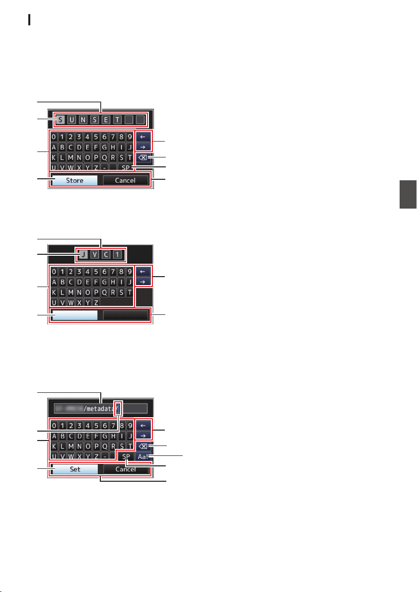
Text Input with Software Keyboard
Use the software keyboard to enter the [Setup
File] subname, [Clip Name Prefix], and the settings
under [Network].
Entering a subname
(A P176
[Configuring Setup Files] )
.
G
A
E
H
C
B
D
F
Entering the [Clip Name Prefix]
(A P156 [ Clip Name Prefix ] )
.
Cancel
Set
A
E
H
C
B
D
Settings under [Network]
The keyboard displayed varies according to the
settings.
(A P
139 [Network Menu] )
.
A
H
C
G
D
B
E
F
I
A
Character Entry Field
0
Field for entering the title.
0
You can enter up to 8 characters for the
[Setup File] subname or up to 4 characters
for the [Clip Name Prefix].
B
Character Cursor
Select a character using the key cursor D, and
press the Set button (R) to input the selected
character at the position of the character cursor.
The character cursor moves to the next position
on the right each time a character is input.
The cursor can be moved using the arrow keys
H.
C
Character Keys
Use the cross-shaped button (JKHI) to move
the key cursor D to the character you want to
enter.
D
Key Cursor
Indicates the currently selected character or
item. Use the cross-shaped button (JKHI) to
move the cursor.
E
Confirmation Buttons
0
Select
[Set]/[Store] and press the Set button
(R) to confirm the title.
0
Select [Cancel] and press the Set button (R)
on the side control panel of the camera
recorder to abort character input and return
to the previous screen.
F
[SP] Space Key
Select [SP] and press the Set button (R) on the
side control panel of the camera recorder to
enter a space at the current position of the
character cursor B.
G
[3 ] Backspace Key
Select [3 ] and press the Set button (R) on the
side control panel of the camera recorder to
delete the character on the left of the character
cursor B.
H
Arrow Keys
Moves the position of the character cursor B.
I
Character Switch Button
Switches the character buttons C to the upper
case, lower case, and symbols.
Basic Operations in Menu Screen
107
Menu Display and Detailed Settings

Menu Screen Hierarchical
Chart
[Main Menu...] ..................................... (A P 108)
- [Camera Function...] ....................... (A P 109)
- [Chroma Aberration] ................... (A P 109)
- [Pixel Mapping] ........................... (A P 109)
- [Shutter] ...................................... (A P 109)
- [AE Level] ................................... (A P 109)
- [AE Speed] ................................. (A P 109)
- [AE Area] .................................... (A P 109)
- [AGC Limit] ................................. (A P 110)
- [Auto Iris Limit (OPEN)] .............. (A P 110)
- [Auto Iris Limit (CLOSE)] ............ (A P 110)
- [EEI Limit] ................................... (A P 110)
- [Smooth Trans] ........................... (A P 110)
- [FAW] ......................................... (A P 110)
- [FAW Speed] .............................. (A P 110)
- [GAIN L] ...................................... (A P 110)
- [GAIN M] ..................................... (A P 110)
- [GAIN H] ..................................... (A P 110)
- [Lens REC] ................................. (A P 111)
- [User Switch Set...] ..................... (A P 111)
- [Full Auto...] ................................ (A P 111)
- [Camera Process...] ........................ (A P 116)
- [Color Space] ............................. (A P 116)
- [Gamma] .................................... (A P 116)
- [Detail] ........................................ (A P 117)
- [Master Black] ............................ (A P 117)
- [Black Paint] ............................... (A P 117)
- [Flare] ......................................... (A P 117)
- [V. Shading] ................................ (A P 117)
- [Black Toe] ................................. (A P 118)
- [Knee Level] ............................... (A P 118)
- [Auto Knee Sensitivity] ................ (A P 118)
- [Auto Knee Peak Filter] ............... (A P 118)
- [White Clip] ................................. (A P 119)
- [Chroma Clip] ............................. (A P 119)
- [White Balance...] ....................... (A P 119)
- [Color Matrix] .............................. (A P 119)
- [Color Gain] ................................ (A P 120)
- [Reverse Picture] ........................ (A P 120)
- [DNR] ......................................... (A P 120)
- [Reset Process] .......................... (A P 120)
- [TC/UB...] ........................................ (A P 124)
- [TC Mode] .................................. (A P 124)
- [TC Preset] ................................. (A P 124)
- [UB Mode] .................................. (A P 124)
- [Drop Frame] .............................. (A P 124)
- [
LCD/VF...] ...................................... (A P 125)
-
[Shooting Assist...] ...................... (A P 125)
- [Marker Settings...] ..................... (A P 125)
- [Display Type...] .......................... (A P 125)
- [Display On/Off...] ....................... (A P 125)
- [VF Color] ................................... (A P 125)
- [LCD Contrast] ............................ (A P 125)
- [LCD Bright] ................................ (A P 125)
- [LCD Peaking] ............................ (A P 125)
- [Convert to ITU709] .................... (A P 125)
- [LCD RGB Gain] ......................... (A P 126)
- [VF RGB Gain] ............................ (A P 126)
- [A/V Set...] ....................................... (A P 131)
- [Video Set...] ............................... (A P 131)
- [Audio Set...] ............................... (A P 135)
- [Network] ........................................ (A P 139)
- [Connection Setup...] .................. (A P 139)
- [Live Streaming...] ...................... (A P 139)
- [Return over IP...] 0 ............ (A P 139)
- [Web...] ....................................... (A P 139)
- [Metadata Server...] .................... (A P 139)
- [Upload Settings] 0 ............ (A P 139)
- [Import Metadata] ....................... (A P 139)
- [Zero Config] .............................. (A P 140)
- [Reset Network] .......................... (A P 140)
- [System...] ....................................... (A P 148)
- [Record Set...] ............................ (A P 148)
- [Media] ....................................... (A P 148)
- [Setup File] ................................. (A P 148)
- [Tally System] ............................. (A P 148)
- [Front Tally] ................................ (A P 148)
- [Back Tally] ................................. (A P 148)
- [GPS] u v ......................... (A P 148)
- [Battery] 0 .......................... (A P 149)
- [Language] ................................. (A P 149)
- [Reset All] ................................... (A P 149)
- [Date/Time] ................................. (A P 149)
- [Date Style] ................................. (A P 150)
- [Time Style] ................................ (A P 150)
- [Time Zone] ................................ (A P 150)
- [Reserved] .................................. (A P 150)
- [System Information] ................... (A P 150)
Memo :
0
Some menus cannot be set depending on the operating mode or status of the camera recorder. These
items are displayed in gray, and they cannot be selected.
0
Setting value with the R mark is the factory default.
108
Menu Screen Hierarchical Chart
Menu Display and Detailed Settings

Camera Function Menu
Menu screen for specifying operation settings
during shooting.
This item can only be selected in the Camera
mode.
Chroma Aberration
For configuring whether to apply ALAC (Auto Lens
Aberration Compensation) to reduce chromatic
aberration of magnification which appears as
colored outlines.
0
Auto:
Configures to ALAC automatically when an
ALAC-compatible lens is used.
0
Off:
Disables the ALAC function.
[Setting Values: RAuto, Off]
Memo :
0
This function does not support CAC lenses,
which adopts a different method of
compensation from ALAC lenses.
0
This function does not correct axial chromatic
aberration.
0
When in the “Auto” mode, chromatic aberration
correction is functioning if chromatic aberration
correction on the status screen (camera) is
configured to “On”.
Pixel Mapping
Detects white spots in the sensor and performs
correction to reduce the defect. To perform pixel
mapping, do so in the Camera mode after attaching
the lens cap.
[Setting Values: Execute, RCancel]
Memo :
0
It is recommended to use the AC adapter as the
power supply.
0
Selection for this item is disabled when [System]
is configured to “High-Speed”2.
Shutter
For specifying shutter-related settings.
When “Slow” or “Step/Variable” is selected,
configure the shutter speed by pressing “SEL” of
the [SHUTTER] switch and using the cross-shaped
button (J K).
The cross-shaped button (H I) can also be used
to switch between step and variable.
0
Slow:
Configures the shutter speed to low speed.
0
EEI:
Select this to perform automatic control of the
shutter.
0
Step/Variable:
Step mode switches the shutter speed in fixed
values. Selecting Variable configures the setting
to variable scan. Use this setting when shooting
a PC monitor.
[Setting Values: Slow, EEI, RStep/Variable]
Memo :
0
When “J-Log1” or “HLG” is selected for [Camera
Process] B [Color Space], “EEI” cannot be
selected.
AE Level
For setting the convergence level during AE (Auto
Exposure).
[Setting Values: -6 to +6 (R0)]
Memo :
0
When “J-Log1” or “HLG” is selected for [Camera
Process] B [Color Space], [AE Level] cannot be
configured.
0
AE
level can also be configured using the cross-
shaped button (J K) after operating the user
button that is assigned with the AE Level
function.
AE Speed
For setting the convergence speed during AE (Auto
Exposure).
[Setting Values: RFast, Middle, Slow]
AE Area
For configuring the AE detection area.
[Setting Values: Center, Bottom, RNormal]
Camera Function Menu
109
Menu Display and Detailed Settings

AGC Limit
For setting the maximum gain value of “AGC”,
which electrically boosts the sensitivity level
according to the brightness automatically.
0
When [LCD/VF] B [Display Type] B [Gain] is set
to “dB”:
[Setting Values: 30 dB, 24 dB, R18 dB, 12 dB,
6 dB]
0
When [LCD/VF] B [Display
Type] B [Gain] is set
to “ISO”:
[Setting Values: ISO 25600, ISO 12800, RISO
6400, ISO 3200, ISO 1600]
Auto Iris Limit (OPEN)
For setting the limit value of the OPEN end when
auto iris is enabled.
[Setting Values: F5.6, F4, F2.8, RF2, Open]
Auto Iris Limit (CLOSE)
For setting the limit value of the CLOSE end when
auto iris is enabled.
[Setting Values: F16, RF11, F8, F5.6]
EEI Limit
For setting the shutter speed control range when
the Automatic Shutter mode (EEI) is enabled.
[Setting Values: 4F-stop, R3F-stop, 2F-stop]
Smooth Trans
For setting the shock reduction function, which
slows down the sudden change when switching
with the [GAIN] or [WHT.BAL] switch.
[Setting Values: On, ROff]
Memo :
0
This function is disabled when AGC is operating.
9
Gain
For configuring the speed at which gain changes
when [Smooth Trans] is set to
“On”.
[Setting Values: Fast, R, Middle, Slow, Off]
9
Shutter
For configuring the speed at which the shutter
changes when [Smooth Trans] is set to
“On”.
[Setting Values: Fast, R, Middle, Slow, Off]
9
White Balance
For configuring the speed at which white balance
changes when [Smooth Trans] is set to
“On”.
[Setting Values: Fast, R, Middle, Slow, Off]
FAW
For setting the position in the white balance switch
[WHT.BAL] to assign the FAW (Full Auto White
Balance) function.
[Setting Values: B, A, PRST, RNone]
FAW Speed
For configuring the operation speed of FAW (Full-
time Auto White Balance)
[Setting Values: RFast, Middle, Slow]
GAIN L, GAIN M, GAIN H
For setting the gain value of each position on the
[GAIN] selection switch.
The setting is fixed at “AGC” in the Full Auto mode.
In addition, the sensitivity setting in [Lolux] is used.
(A P113 [ Lolux ] )
0
When [LCD/VF] B [Display
Type] B [Gain] is set
to “dB”:
[Setting Values: AGC, 30 dB, 27 dB, 24 dB, 21
dB, 18 dB, 15 dB, 12 dB, 9 dB, 6 dB, 3 dB, 0 dB,
-3 dB, -6 dB]
(Default values for GAIN L: 0dB, GAIN M: 6dB,
GAIN H: 12dB)
0
When [
LCD/VF] B [Display Type] B [Gain] is set
to “ISO” and [Camera Process] B [Color
Space] is set to a value other than “HLG”:
[Setting Values: AGC, ISO25600, ISO20000,
ISO16000, ISO12800, ISO10000, ISO8000,
ISO6400, ISO5000, ISO4000, ISO3200,
ISO2500, ISO2000, ISO1600, ISO1250,
ISO1000, ISO800, ISO640, ISO500, ISO400]
(Default values for GAIN L: ISO800, GAIN M:
ISO1600, GAIN H: ISO3200)
Memo :
0
“AGC” cannot be selected when “J-Log1”
or
“HLG”
is selected for [Camera Process] B [Color
Space].
0
When “J-Log1” is selected for [Camera
Process] B [
Color Space], the base ISO speed
for achieving the 800% dynamic range of [J-
Log1] is “[ISO1000]”. The square brackets
appear only in the case of the base ISO.
110
Camera Function Menu
Menu Display and Detailed Settings

Lens REC
For selecting a function to be assigned to the
Record button (VTR button, etc.) on the lens.
A menu is displayed only when the FS-790 or
FS-900 is connected.
0
Intercom2:
Turns on/off the Intercom 2 connection.
0
Intercom1:
Turns on/off the Intercom 1 (intercom)
connection.
0
Rec:
Starts/stops recording.
[Setting Values: Intercom2, Intercom1, RRec]
Memo :
0
This function is available when it can be
assigned to the Record button (VTR button, etc.)
on the lens in use.
0
Configure to “Intercom1” when configuring the
intercom with the FS-790 connected.
0
When the FS-900 or FS-790 is connected, the
functions of “Intercom1” and “Intercom2” can
also be assigned to a user button.
User Switch Set...
For specifying user button related settings.
(A P111 [User Switch Set Item] )
Full Auto...
For configuring the Full Auto settings.
(A P115 [Full Auto Item] )
User Switch Set Item
USER0 to USER8, USER9J, USER10K,
USER11
H, USER12I, USER13R (front),
USER1 (VF), USER2 (VF), LENS RET
The preconfigured function can be operated (on/
off, start, switch) by assigning one of the functions
in the following menu table to [USER0], [USER1],
[USER2], [USER3], [USER4], [ONLINE/5],
[USER6], [USER7], [USER8], [J/9], [K/10], [H/11],
[I/12], front [SET/USER13] button, [RET] button
on the lens and the [USER1(VF)] and [USER2(VF)]
buttons on the viewfinder.
Set according to the shooting conditions. Usable in
the Camera mode.
(A P45 [Assignment of Functions to User
Buttons] )
Memo :
0
When a viewfinder is connected, priority is given
to the [ZEBRA] switch of the viewfinder and the
user button that is assigned with the “Zebra”
function will not function.
0
“Focus Assist +” is a combination of the
“Focus
Assist” and “Expanded Focus” functions.
0
“Skin Detail +
” is a combination of the “Skin
Detail” and “Skin Area” functions.
0
The
[SET/USER13] button at the front functions
as the [STATUS/SET] button in the factory
setting, but it can also be assigned with the
[USER13] function.
0
If “VF Display
” is assigned to the [USER1(VF)]
or [USER2(VF)] button of the viewfinder, the
button can also be used in the Media mode.
Camera Function Menu
111
Menu Display and Detailed Settings

The settable values for each item are as follows.
Button
Setting Value
[8] [5]/[6]/[7]/
[LENS RET]
[0]/[1]/
[3]/[4]/
[9]/[10]/
[11]/[12]/
[13]
[2] [USER1(VF)]/
[USER2(VF)]
VF Display
c
c c b c
Cancel
c b b b b
Status
c c c b c
Slot Select
c c c b c
Auto Upload 1
c c c
b
b
Return over IP 0
c c c b b
Live Streaming
c c c b b
Load Picture File
c c c b b
Return Video
c c c b c
Clip Review
c c c b c
OK Mark
c c c b c
Clip Cutter Trig 0
c c c b c
Backup Trig 0
c c c b b
Rec
b c b b b
LCD Backlight
c c c b b
Spot Meter
c c c b c
Focus Assist
c c c c c
Expanded Focus
c c c b c
Focus Assist +
c c c b b
Marker
c c c c b
Zebra
c c c b b
Video Signal Monitor
c c c b c
AWB
c c c b c
White Balance
c c c b c
Black Compress
c c c c b
Black Stretch
c c c c b
Skin Detail
c c c b b
Skin Area
c c c b b
Skin Detail +
c c c b b
Zoom Wide
c c c b b
Zoom Tele
c c c b b
FULL AUTO
c c c c c
AE Level
c c c b b
AE Lock
c c c b c
Variable Gain
c c c b b
Lolux
c c c c c
None
c c c c c
c
: Settable
b
: Not settable
112
Camera Function Menu
Menu Display and Detailed Settings

Lolux
To increase the sensitivity when in dim
surroundings, set a value in the Lolux mode.
0
When [LCD/VF] B [Display Type] B [Gain] is set
to “dB”:
[Setting Values: 42 dB, R36 dB, 30 dB, 24 dB]
0
When [LCD/VF] B [Display
Type] B [Gain] is set
to “ISO”:
[Setting Values: ISO 102400, RISO 51200, ISO
25600, ISO 12800]
Clip Review
For configuring the behavior when operating the
user button that is assigned with the “Clip
Review
” function.
0
Last 5sec:
Views about 5 seconds of the clip from the
ending.
0
Top 5sec:
Views about 5 seconds of the clip from the
beginning.
0
Clip:
Views the entire clip.
[Setting Values: RLast 5sec, Top 5sec, Clip]
Spot Meter
For configuring the behavior when operating the
user button that is assigned with the “Spot Meter”
function.
0
Max & Min:
Displays the brightest and darkest areas of the
image.
0
Max:
Displays the brightest area of the image.
0
Min:
Displays the darkest area of the image.
0
Manual:
Displays the image brightness at a specified
position.
[Setting Values: RMax & Min, Max, Min, Manual]
Memo :
0
When “HLG” is selected in [Camera Process] B
[Color Space], the value of the spot meter
changes according to the setting of [LCD/VF] B
[Convert to ITU709]/[White Level].
AE Lock
For configuring the behavior when operating the
user button that is assigned with the “AE Lock”
function.
0
FAW:
Use this to fix the FAW (Full-time Auto White
Balance) function to the value when the user
button assigned with “AE Lock” is pressed.
0
AE:
Use this to fix the Auto function of Gain, Iris, or
Shutter to the value when the user button
assigned with “AE Lock” is pressed.
0
AE/FAW:
Use this to fix the FAW (Full-time Auto White
Balance) function
and the Auto function of Gain,
Iris, or Shutter to the value when the user button
assigned with “AE Lock” is pressed.
[Setting Values: FAW, RAE, AE/FAW]
Memo :
0
This feature only works when Iris, Shutter, Gain
or White Balance is set to Auto mode.
0
“AE Lock” is canceled when the user button
assigned with “AE Lock” is pressed, or when any
of the functions that can be locked is operated
regardless of the mode (Manual or Auto).
0
“AE
Lock” is canceled when the lens extender is
operated and when the iris is adjusted by 2/3
(two-third) stop or more.
0
“AE Lock” is canceled in the following cases.
0
When the user button that is assigned with
“AE Lock” is pressed
0
When
changes are made to the iris (including
operation of the lens extender), gain and
shutter settings
0
When changes are made to the AE level
0
When there is a switch between the Camera
and Media modes
Zoom Speed
For configuring the zoom speed when operating
the user button that is assigned with “Zoom Tele”
or “Zoom Wide”.
Increasing the value increases the speed.
[Setting Values: 8 to R 5 to 1]
Camera Function Menu
113
Menu Display and Detailed Settings

Expanded Focus
For configuring the behavior when operating the
user button that is assigned with the “Expanded
Focus” function.
0
Limited Time:
Activates the timer.
Turns off the “Expanded Focus
” function about
3 seconds after the user button assigned with
“Expanded Focus” is pressed.
0
Momentary:
The
“Expanded Focus
” function is enabled
during the interval while the user button
assigned with “Expanded Focus” is pressed.
0
Toggle:
Pressing the user button assigned with
“
Expanded Focus” each time switches the
“Expanded Focus” function to on or off.
[Setting Values: Limited Time, Momentary,
RToggle]
Memo :
0
When “Toggle” is selected after assigning the
expanded focus to any of the [J/9], [K/10], [H/
11], [I/12] buttons, press the [CANCEL/
RESET] button if you want to disable the
function.
Video Signal Monitor
For configuring the behavior when operating the
user button that is assigned with the “Video Signal
Monitor” function.
0
Switch in Order:
Pressing the button each time switches the
mode in the following sequence: Vectorscope,
Waveform, Histogram 2, Off.
0
On/Off:
Switches
the function configured in [LCD/VF] B
[Shooting Assist] B [Video Signal Monitor] to on
or off.
[Setting Values: RSwitch in Order, On/Off]
Return Video
For configuring the behavior when operating the
user button that is assigned with the “Return
Video” function.
0
CameraGPiP:
Pressing the user button assigned with the
“Return Video” function each time toggles
between the captured video and picture-in-
picture return video.
0
CameraRPiP:
The picture-in-picture return video is displayed
when the user button assigned with the “Return
Video” function is pressed and held down, and
the captured video is displayed when the button
is released.
0
PiPRCamera:
The captured video is displayed when the user
button
assigned with the “Return Video” function
is pressed and held down, and the picture-in-
picture return video is displayed when the button
is released.
0
PiPRReturn:
The return video is displayed when the user
button assigned with the “Return Video” function
is pressed and held down, and the picture-in-
picture return video is displayed when the button
is released.
0
CameraRReturn:
The return video is displayed when the user
button assigned with the “Return Video” function
is pressed and held down, and the captured
video is displayed when the button is released.
[Setting Values: CameraGPiP, CameraRPiP,
PiPRCamera, PiPRReturn, RCameraRReturn]
114
Camera Function Menu
Menu Display and Detailed Settings

Full Auto Item
For configuring the operation of each item in the
Full Auto mode.
Full Auto can be turned on/off using the user button
assigned with the “Full Auto” function.
Gain
For specifying the Gain operation.
0
AGC:
Sets the gain to Auto.
0
SW Set:
Follows the setting of the [GAIN] switch.
[Setting Values: RAGC, SW Set]
Iris Control
For specifying the Iris control operation.
0
Auto:
Sets the iris to Auto.
0
SW Set:
Follows the setting of the [IRIS A/M] switch on
the lens.
[Setting Values: RAuto, SW Set]
Memo :
0
This item can be specified even if the lens used
does not have iris function.
Shutter
For specifying the Shutter operation.
0
EEI:
Sets the shutter to Auto.
0
SW Set:
Follows the setting of the [SHUTTER]
switch.
[Setting Values: REEI, SW Set]
White Balance
For specifying the White Balance operation.
0
FAW:
Sets the white balance to Auto.
0
SW Set:
Follows the setting of the [WHT BAL] switch.
[Setting Values: RFAW, SW Set]
Audio
For configuring the audio operation.
0
Auto:
Sets the audio sound to Auto.
0
SW Set:
Follows the settings of the
[AUDIO CH1/2/3/4]
-
[MANUAL/AUTO] switches.
[Setting Values: RAuto, SW Set]
Camera Function Menu
115
Menu Display and Detailed Settings

Camera Process Menu
Menu screen for adjusting the quality of camera
images.
This item cannot be selected in the Media mode.
Color Space
For configuring the color space that is used inside
the camera.
The gamma and color gamut change automatically
according to the selected color space.
When [System] is configured to a setting other than
“SD” and “SD(SDI In)”
0
J-Log1:
Color
space that supports 800% dynamic range
and log gamma
0
HLG:
Color space that supports the ITU2100 HLG
HDR
0
ITU2020:
Color space that supports the ITU2020 wide
color gamut
0
ITU709:
ITU709 color space
[Setting Values: J-Log1, HLG, ITU2020, RITU709]
When [System] is set to “SD” or “SD(SDI In)” 2
0
ITU601 (EBU):
Color space that supports the EBU color gamut
0
ITU601 (170M):
Color space that supports the SMPTE170M
color gamut
0
ITU709:
ITU709 color space
[Setting Values: ITU601 (EBU), ITU601 (170M),
RITU709]
Memo :
0
When [System] is set to
“HD” and when “J-
Log1”
or “HLG” is selected, some menu items
under [Camera Process] cannot be configured.
0
The AE function does not function when
“J-
Log1” or “HLG” is selected. When the [AUTO
IRIS] switch on the lens is set to “AUTO”, the iris
is fixed at “F4”.
9
Colorimetry
For configuring the standard for converting R, G, B
signals to Y, Cb, Cr signals when [Color Space] is
configured to “HLG” or “ITU2020”.
0
ITU2020:
Records and outputs ITU2020 RGB signals
using
the Y-Cb-Cr signal conversion coefficient.
0
ITU709:
Records and outputs ITU709 RGB signals using
the Y-Cb-Cr signal conversion coefficient.
[Setting Values: RITU2020, ITU709]
Memo :
0
This item is available when [Color Space] is set
to “HLG” or “ITU2020”.
0
This is fixed at
“ITU709” when [Color Space] is
set to “J-Log1” or “ITU709”.
0
This
is fixed at “ITU601” when [System] is set to
“SD” 2.
Gamma
For adjusting the gamma curve that determines the
gradation expression.
(A P173 [Adjusting the Gamma] )
0
Cinema 2:
Sets to a gamma curve with soft expression
giving priority to high luminance gradation.
0
Cinema 1:
Sets to a gamma curve with similar gradation to
the screen characteristics of movies.
0
Standard:
Sets to a standard gamma curve.
0
Off:
Does not perform adjustment.
[Setting Values: Cinema 2, Cinema 1, RStandard,
Off]
Memo :
0
[Gamma] cannot be configured when [Color
Space] is set to “HLG” or “J-Log1”. “HLG
Gamma” is used during “HLG” and “J-Log1
Gamma” is used during “J-Log1”.
116
Camera Process Menu
Menu Display and Detailed Settings

9
Level
The amount of correction can be specified
separately when [Gamma] is set to “Standard”,
“Cinema 1” or “Cinema 2”.
When [Gamma] is set to “Standard”
[Setting Values: 0.35 to R 0.45 to 0.55 (in steps of
0.01)]
0
Increase the number:
Finer gradation at bright areas and coarser
gradation at dark areas.
0
Decrease the number:
Finer gradation at dark areas and coarser
gradation at bright areas.
When [Gamma] is
set to “Cinema 1” or “Cinema 2”
[Setting Values: +10 to R 0 to -10]
0
Increase the number:
Finer gradation at dark areas and coarser
gradation at bright areas.
0
Decrease the number:
Finer gradation at bright areas and coarser
gradation at dark areas.
Memo :
0
When [Gamma] is set to “Standard” with the
value set at [0.45], the gamma adjusted
conforms to ITU709 or ITU2020.
0
If
[Gamma] is set to “Cinema 2”, the maximum
peak signal decreases from 109% as the
number becomes smaller in the setting values
from 0 to -10. When the level is at -10, the video
input with a dynamic range of 600% will be kept
within a 100% output.
0
The level cannot be configured when [Gamma]
is set to “Off” or [Color Space] is set to “HLG” or
“J-Log1”.
Detail
For adjusting the contour (detail) enhancement
level.
Increasing the value increases the sharpness of
the contour.
[Setting Values: +20 to -20, Off] (Default Value: -6
for “J-Log1” and “HLG” of Color Space; 0 for all
other settings)
Memo :
0
The setting values of this item and [Adjust...] are
stored separately when [Color Space] is set to
“HLG” or “J-Log1”.
9
Adjust...
For specifying the detailed settings of the contour
(detail).
(A P
121 [Detail/Adjust Item] )
Memo :
0
This item cannot be selected when [Detail] is set
to “Off”.
Master Black
For adjusting the pedestal level (master black) that
serves as the reference black.
Increasing the value increases the pedestal.
[Setting Values: +50 to +1, R0, -1 to -50]
Memo :
0
This item cannot be configured when [Color
Space] is set to “J-Log1”.
0
The
setting
value of this item is stored separately
when [Color Space] is set to “HLG”.
Black Paint
For
adjusting the R (red) and B (blue) components
of black.
[Setting Values: +50 to +1, R0, -1 to -50]
Memo :
0
This item cannot be configured when [Color
Space] is set to “J-Log1” or “HLG”.
Flare
Performs flare correction.
[Setting Values: ROn, Off]
9
Master Flare
Performs correction to prevent the entire image
from turning white due to light that enters the lens.
The image appears blacker with a larger value, and
whiter with a smaller value.
[Setting Values: +20 to +1, (R0), -1 to -20]
Memo :
0
This item cannot be configured when [Color
Space] is set to “J-Log1” or “HLG”.
9
Flare Balance
For adjusting the balance between R (red) and B
(blue).
[Setting Values: +10 to +1, (R0), -1 to -10] (R/B)
V. Shading
For adjusting shading (color shift) in the vertical
direction which occurs due to the lens
characteristics.
0
On:
For adjusting shading.
0
Off:
Fixes shading adjustment. Manual adjustment
is not allowed.
[Setting Values: On, ROff]
9
Adjust
Performs vertical shading adjustment when [V.
Shading] is set to “On”.
[Setting Values: -128 to R 0 to +127]
(A P67 [Vertical Shading Adjustment] )
Camera Process Menu
117
Menu Display and Detailed Settings

Black Toe
Process the dark areas according to the balance of
bright and dark areas in the image to adjust the
overall balance of contrast.
For altering the gain of dark areas. Adjust this item
according to the condition of the captured video
signals.
0
Stretch:
Increases the gain of dark areas in an image to
stretch the signals of these areas only, thereby
showing the contrast between bright and dark
areas more clearly.
Specify the amount of stretch with [Stretch
Level].
0
Normal:
Normal condition.
0
Compress:
Compresses the gain of dark areas to increase
the contrast when the entire image appears
bright and contrast is weak. Specify the
compression amount with [Compress Level
].
[Setting Values: Stretch, RNormal, Compress]
Memo :
0
This item cannot be configured when [Color
Space] is set to “J-Log1” or “HLG”.
0
When “Black Stretch” or “Black Compress” is
assigned
to the [USER2] switch, priority is given
to the user button setting and configuration
using the menu is disabled.
9
Stretch Level
Stretch amount increases when a larger value is
specified.
[Setting Values: 5 to 1 (R 3)]
Memo :
0
This item is displayed only when [Black Toe] is
set to “Stretch”. Otherwise, this item appears as
“---” and cannot be selected.
0
This item cannot be configured when
[Color
Space] is set to “J-Log1” or “HLG”.
9
Compress Level
Compression amount increases when a larger
value is specified.
[Setting Values: 5 to 1 (R 3)]
Memo :
0
This item is displayed only when [Black Toe] is
set to “Compress”. Otherwise, this item appears
as “---” and cannot be selected.
0
This item cannot be configured when [Color
Space] is set to “J-Log1
” or “HLG”.
Knee Level
For specifying the start point (knee point) for
compressing the video signal to show the gradation
of the highlighted portion. Set the [OUTPUT] switch
to “AUTO KNEE OFF”.
[Setting Values: 109.0%, 107.5%, 105.0%,
102.5%, 100.0%, 97.5%, R 95.0%, 92.5%, 90.0%,
87.5%, 85.0%, 82.5%, 80.0%, 77.5%, 75.0%,
72.5%, 70.0%]
Memo :
0
This item cannot be configured when [Color
Space] is set to “J-Log1” or “HLG” and when
[Gamma] is set to “Cinema 2”.
Auto Knee Sensitivity
For configuring the response speed of the knee
operation when the [OUTPUT] switch is set to
“AUTO KNEE ON”. Set to “Slow” when shooting an
object under a condition where there is drastic
change in the light intensity.
[Setting Values: RFast, Middle, Slow]
Memo :
0
This item cannot be configured when [Color
Space] is set to
“J-Log1” or “HLG” and when
[Gamma] is set to “Cinema 2”.
Auto Knee Peak Filter
For configuring the response speed of the knee
operation with respect to a high-luminance point
light source and the like when the [OUTPUT] switch
is set to “AUTO KNEE ON”.
[Setting Values: RHigh, Middle, Low]
Memo :
0
This item cannot be configured when [Color
Space] is set to “J-Log1” or “HLG” and when
[Gamma] is set to “Cinema 2”.
118
Camera Process Menu
Menu Display and Detailed Settings

White Clip
For setting the point to apply white clip for video
signals with a high luminance level.
[Setting Values: 109% to 90% (R109%)]
Memo :
0
Set this item to 100% if the screen becomes too
white with a setting value above 100% or when
the system in use limits Y signals within 100%.
0
The setting value of this item is stored separately
when [Color Space] is set to “HLG” or “J-Log1”.
9
RGB Gamut Clip
2
For configuring whether to the clip the RGB signals
at the same time when clipping the luminance
signal using the settings in [White Clip].
0
On: Performs gamut clipping using the settings
in [White Clip] for video signals with a high RGB
signal level. Performs gamut clipping according
to the settings in [White Clip] for negative signal
levels.
[Setting Values: On, ROff]
Memo :
0
The area that is subject to gamut clipping when
“On” is configured is as follows.
Example:
0
[White Clip] 103 %
・RGB signal: 103 % or above
・Negative level: -3 % or below
0
[White Clip]100 % or below
・RGB signal: Equivalent to or higher than the
preset value in [White Clip]
・Negative level: 0 % or below
0
When RGB gamut clipping for EBU-R103 is
supported, this feature can be configured to
“On
” and the value of [White Clip] can be
adjusted to a desired level that is 104 % or lower.
0
The setting value of this item is stored separately
when [Color Space] is set to “HLG” or “J-Log1”.
Chroma Clip
For configuring the point to apply chroma clipping
for video signals with a high color difference level.
[Setting Values: 113% to 90% (R113%)]
Memo :
0
When this is set to 100%, the Cb-Cr signal will
be clipped so that it falls within the 64-960 range
of the ITU 10-bit video standard.
0
When [Color Space] is set to “HLG” or “J-Log1”,
the settings will be saved separately.
White Balance...
Menu for adjusting white balance.
(A P122 [White Balance Item] )
* For details, refer to “[Adjusting the White
Balance] (A P 63)”.
Color Matrix
For setting the color matrix.
0
Natural:
Sets to a brighter and more natural color matrix
than the standard. Effective for shooting under
a strong single color light source such as stage
lightings.
0
Cinema Subdued:
Sets to a subdued color matrix that is similar to
the screen characteristics of movies.
0
Cinema Vivid:
Sets to a vivid color matrix that is similar to the
screen characteristics of movies.
0
Standard:
Sets to a standard color matrix.
0
Off:
Sets the color matrix function to Off.
[Setting Values: Natural, Cinema Subdued,
Cinema Vivid, RStandard, Off]
Memo :
0
This item cannot be configured when [Color
Space] is set to “J-Log1”.
0
This is fixed at
“Standard” when [Color Space]
is set to “HLG”.
Camera Process Menu
119
Menu Display and Detailed Settings

9
Adjust
This item is used to adjust [Color Matrix] to a color
according to the user’s preference.
The adjusted values of “Natural”, “Standard”,
“Cinema Vivid”, and “Cinema Subdued” in [Color
Matrix] can be stored individually.
o
Linear Adjust:
The saturation, hue and brightness of the
primary and complementary colors (6 colors in
total) can be set individually when
“On
” is
configured.
o
Multi Adjust:
The saturation and hue of the 16 hue axes (R/R
+/Mg-/Mg/B-/B/B+/Cy-/Cy/Cy+/G-/G/G+/Yl/Yl
+/R-) can be set when “On” is configured.
When the USER1 button is pressed while the
multi adjustment screen is displayed, only the
colors of the hue under adjustment remain in the
following cases. The other colors become black
and white.
0
LCD monitor and viewfinder video images
0
[HD/SD SDI OUT2] terminal output when [A/V
Set]→[SDI OUT2] is set to “VF”
0
[HDMI]
terminal output when [A/V Set]→[HDMI
OUT] is set to “VF”
(A P174
[Adjusting Color Matrix] )
Memo :
0
This item cannot be configured when [Color
Space] is set to “J-Log1”.
0
The
setting value of this item is stored separately
when [Color Space] is set to “HLG”.
Color Gain
For adjusting the video signal color level.
Increasing the value deepens the color.
[Setting Values: +15 to -50, Off (R0)]
Memo :
0
Images are displayed in black-and-white when
this is set to “Off”.
0
This item cannot be configured when [Color
Space] is set to “J-Log1”.
0
The
setting value of this item is stored separately
when [Color Space] is set to “HLG”.
Reverse Picture
For recording images correctly by setting this item
to “Rotate” when the lens image appears upside
down or laterally inverted.
0
Rotate:
Enables horizontal/vertical inversion of the
image.
0
Off:
Disables horizontal/vertical inversion of the
image.
[Setting Values: Rotate, ROff]
DNR
Decreases noise in the image.
[Setting Values: High, RMiddle, Low]
Reset Process
Restores all items in the [Camera Process] menu
to their default settings.
120
Camera Process Menu
Menu Display and Detailed Settings

Detail/Adjust Item
V/H Balance
For setting the H/V balance to enhance contour
(detail)
in
the horizontal (H) or vertical (V) direction.
0
H+1 to H+20:
Increasing the value enhances contour in the
horizontal direction.
0
V+1 to V+20:
Increasing the value enhances contour in the
vertical direction.
[Setting Values: H+20 to H+1, RNormal, V+1 to V
+20]
H Frequency
For specifying the correction frequency of the
horizontal contour. Set this according to the object.
0
High:
Emphasizes the high frequency range. Use this
when shooting objects with fine patterns.
0
Middle:
Emphasizes the intermediate frequency range.
0
Low:
Emphasizes the low frequency range. Use this
when shooting objects with large patterns.
[Setting Values: High, RMiddle, Low]
V Frequency
For specifying the correction frequency of the
vertical contour. Set this according to the object.
0
High:
Emphasizes the high frequency range.
0
Middle:
Emphasizes the intermediate frequency range.
0
Low:
Emphasizes the low frequency range.
[Setting Values: High, RMiddle, Low]
Coring
For configuring the degree of enhancement with
respect to low-level signals (noise, etc.) with subtle
“outline” enhancement.
Applies outline enhancement to even low-level
signals when the setting is closer to -20, and outline
enhancement of low-level signals becomes less
noticeable with noise suppressed when the setting
is closer to +20.
[Setting Values: +20 to +1, R0, -1 to -20]
Level Depend
Configure this item when areas such as the darker
portions of the video image appear coarse when
the Detail function is applied.
+1 reduces the outline enhancement of dark areas
and suppresses the noise, while -1 enhances the
outline of dark areas.
[Setting Values: +1, R0, -1]
Posi Gain
For configuring the amount of detail in the white
direction of the outline enhancement signals.
[Setting Values: +20 to +1, R0, -1 to -20]
Nega Gain
For configuring the amount of detail in the black
direction of the outline enhancement signals.
[Setting Values: +20 to +1, R0, -1 to -20]
Knee Gain
For configuring the amount of detail at the highlight
areas of the video image. A larger value further
enhances the outline of the signals at the highlight
areas. While a smaller value reduces the outline of
the highlight areas, moire (aliasing) due to white
clipping at the highlight areas is also less likely to
occur.
[Setting Values: 32 to R16 to 0]
Memo :
0
This item cannot be configured when [Color
Space] is set to “J-Log1” or “HLG”.
Skin Detail
Detects the skin tone and smooths the outline.
[Setting Values: On, ROff]
9
Level
For configuring the outline correction level when
[Skin Detail
] is set to “On”.
The smaller the number, the smoother the video.
[Setting Values: -1 to R -5 to -10]
Camera Process Menu
121
Menu Display and Detailed Settings

Skin Area
For configuring whether to display only the color
correction area in color and areas that are not
corrected in black-and-white.
0
On:
When “Detect” of [Skin Color Adjust] is
functioning, only the detected color is displayed
in color and the other areas are displayed in
black-and-white in the following cases.
0
LCD monitor and viewfinder video images
0
[HD/SD SDI OUT2] terminal output when
[A/V Set] B [SDI OUT2] is set to “VF”
0
[
HDMI] terminal output when [A/V Set] B
[HDMI OUT] is set to “VF”
0
Off:
Displays all the colors.
[Setting Values: On, ROff]
Skin Color Adjust
For configuring details of the skin color.
0
Detect
For detecting the skin tone.
[USER1]Stop appears when detection is in
progress and [USER1]Execute appears while
detection is stopped.
[Setting Values: Execute, Stop]
0
Saturation
Selecting a larger value widens the saturation
range of the color to be corrected, while a
smaller value reduces the color saturation
range.
[Setting Values: +10 to R0 to -10]
0
Width
Although selecting a larger value widens the hue
range of the color to be corrected and eases
identification, it also increases the likelihood of
erroneous correction. Selecting a smaller value
narrows down the hue range, but helps to
reduce erroneous correction at the same time.
[Setting Values: +10 to R0 to -10]
White Balance Item
Preset Temp.
For setting the color temperature when the
[WHT.BAL] switch is set to
“PRST”.
For details, refer to “[Adjusting the White Balance]
(A P 63)”.
Alternative Temp.
For setting the alternative color temperature in the
Preset mode.
When the [WHT.BAL] switch is set to “PRST”,
pressing the user button assigned with the “AWB”
function each time switches the color temperature
setting in the Preset mode. ([Preset
Temp.]1[Alternative Temp.])
For details, refer to “[Adjusting the White Balance]
(A P 63)”.
Preset Paint Memory
For configuring whether to configure the color
temperature individually or collectively in the
Preset mode. Adjustment is performed in [Preset
Paint].
0
Individual:
Each of the 9 types of color temperatures
(2300K, 3000K, 3200K, 4200K, 4800K, 5200K,
5600K, 6500K, 7500K) are configured
individually.
0
Common:
The
entire color temperature range is configured
collectively.
[Setting Values: Individual, RCommon]
Preset Paint
For adjusting the R (red) and (B) blue components
in the Preset mode.
0
Increase the number:
Strengthens the red/blue.
0
Decrease the number:
Weakens the red/blue.
[Setting Values: +32 to -32 (R 0)]
122
Camera Process Menu
Menu Display and Detailed Settings

AWB Paint
For adjusting the R (red)/B (blue) component in the
AWB (Auto White Balance) mode.
For details, refer to “[Adjusting the White Balance]
(A P 63)”.
0
Increase the number:
Strengthens the red/blue.
0
Decrease the number:
Weakens the red/blue.
[Setting Values: -32 to +32 (R 0)]
Memo :
0
This item is selectable when the [WHT.BAL]
switch is set to “A” or “B”. When “PRST” is set,
this item appears as “---” and cannot be
selected.
0
Different values can be specified for “A” and “B”.
0
When [Clear Paint After AWB] is set to “On”,
pressing the user button that is assigned with the
“AWB” function to readjust the white balance
switches the R and B values automatically to
“0”.
Clear Paint After AWB
For specifying whether to clear the [AWB Paint] (R
value and B value) settings after executing AWB
(Auto White Balance).
0
On:
Sets the [AWB Paint] (R value and B value)
settings to “0” after executing AWB (Auto White
Balance).
0
Off:
Does not change the [AWB Paint
] (R value and
B value) settings after executing AWB (Auto
White Balance).
[Setting Values: ROn, Off]
FAW Paint
For adjusting the R (red)/B (blue) component
during FAW (Full Auto White Balance) mode.
0
Increase the number:
Strengthens the red/blue.
0
Decrease the number:
Weakens the red/blue.
[Setting Values: -32 to +32 (R 0)]
Camera Process Menu
123
Menu Display and Detailed Settings

TC/UB Menu
Menu screen for setting time code and user’s bit.
This item cannot be selected in the Media mode,
or during recording.
TC Mode
For configuring the TC mode settings.
0
SW Set:
Follows the settings of the [TC GEN] switch.
0
Clock:
This is set to “Clock” when the [TC GEN] switch
is set to “F-RUN”.
[Setting Values: RSW Set, Clock]
Memo :
0
When
the [TC GEN] selection switch is set to “R-
RUN” or “REGEN”, or during “Interval
Rec”1, “Frame Rec”1 and “High-
Speed”2, the setting is fixed at “SW Set”.
TC Preset
For setting the time code (hour, minute, second,
frame).
Display : Drop setting 02:02:25.20
: Non Drop setting 02:02:25:20
(A P74 [Setting Time Code Generator] )
Memo :
0
When the [TC GEN] switch is set to “REGEN”,
“<Regen>” is displayed and preset is disabled.
0
When [TC Mode
] is set to “Clock”, “<Clock>” is
displayed and preset is disabled.
UB Mode
For setting the recording mode of the user’s bit.
0
Date:
Records the date.
0
Time:
Records the time.
0
Preset:
Records according to the preset setting.
(A P77 [Setting the User’s Bit] )
[Setting Values: Date, Time, RPreset]
Memo :
0
If [UB Mode] is set to “Time”, the user’s bit
operates in the 24-hour format even if the LCD
display is in the 12-hour format.
9
Preset
For setting the user’s bit. (Digit by digit)
Display : AB CD EF 01
(A P77 [Presetting the User’s Bit] )
Memo :
0
When [UB Mode] is set to “Date” or “Time”, this
item appears as “---” and preset is disabled.
0
When the [TC GEN
] switch is set to “REGEN”,
“<Regen>” is displayed and preset is disabled.
Drop Frame
For setting the framing mode of the time code
generator.
0
Non Drop:
Internal time code generator works in the non-
drop-frame mode. Use this setting when placing
emphasis on the number of frames.
0
Drop:
Internal time code generator works in the drop-
frame mode. Use this setting when placing
emphasis on the recording time.
[Setting Values: Non Drop, RDrop]
Memo :
0
This item can be set only when [System] B
[Record Set] B [Record Format] B [WFrame
Rate] is set to “60p”, “30p”, or “60i”. When
[Frame Rate] is “24p”2, “Non Drop”
becomes fixed and cannot be selected. When
[Frame Rate] is “50p”, “25p”, or “50i”, this item
appears as “---” and cannot be selected.
(A P
152 [ W Frame Rate ] )
124
TC/UB Menu
Menu Display and Detailed Settings

LCD/VF Menu
Item for specifying settings related to the LCD
monitor or viewfinder screen.
This menu screen can be used to specify settings
related to the Focus Assist mode, zebra pattern
display, screen size, marker, and safety zone. In
addition, it is also used for selecting whether to
display characters on the LCD monitor or
viewfinder screen, as well as for adjusting the
picture quality of the LCD monitor.
Shooting Assist...
Menu for setting the Shooting Assist function.
(A P126 [Shooting Assist Item] )
Marker Settings...
For setting items such as the safety zone and
center mark.
(A P128 [Marker Settings Item] )
Display Type...
For specifying display-related settings.
(A P129 [Display Type Item] )
Display On/Off...
For configuring the on/off setting of the screen
display.
(A P130 [Display On/Off Item] )
VF Color
For selecting whether to display the image on the
viewfinder screen in color or black-and-white.
Select “On” to display in color, and “Off” to display
in black-and-white.
[Setting Values: ROn, Off]
LCD Contrast
For setting the difference in luminance between the
darkest and brightness areas in the LCD monitor.
Increasing the value increases the contrast.
[Setting Values: +10 to +1, R0, -1 to -10]
LCD Bright
For configuring the brightness of the LCD monitor.
Increasing the value increases the brightness.
[Setting Values: +10 to +1, R0, -1 to -10]
LCD Peaking
For adjusting the outline of the image displayed on
the LCD monitor.
[Setting Values: +10 to +1, R0, -1 to -10]
Convert to ITU709
When [Color Space] is set to “ITU2020”, “J-Log1”
or “HLG”, the video images on the LCD monitor and
viewfinder are converted to the ITU709 color space
for display.
0
When [A/V Set] B [Video Set] B [SDI OUT2]
is
set to “VF”, the [HD/SD SDI OUT2] terminal
output is also converted.
0
When [A/V Set] B[Video Set] B [HDMI
OUT] is set to
“VF”, the [HDMI] terminal
output is also converted.
0
Cam + Return:
The camera and return videos are converted
from the color space configured in [Color
Space
] to the ITU709 color space.
0
Cam:
Only the camera video is converted to the
ITU709 color space.
0
Off:
Not converted.
[Setting Values: Cam + Return, Cam, ROff]
Memo :
0
This item can be configured only when [Color
Space] is set to “ITU2020”, “J-Log1” or “HLG”.
LCD/VF Menu
125
Menu Display and Detailed Settings

9
White Level
For configuring the white level during adjustment of
the dynamic range that is visible in the LCD monitor
or viewfinder when [Color Space] is set to “HLG”.
When [Color Space] is set to “HLG” and [Convert
to ITU709] is set to a value other than “Off”, this item
can be used to configure the output luminance level
(%) of HLG videos that corresponds to 100% on
the ITU709 gamma curve during the conversion.
[Setting Values: 80.0%, 77.5%, 75.0%, R 72.5%,
70.0%, 67.5%,65.0%, 62.5%, 60.0%, 57.5%,
55.0%, 52.5%, 50.0%]
Memo :
0
This item can be configured only when [Color
Space] is set to “HLG”.
0
The
value on the spot meter changes in tandem
with this setting.
Example: When [White Level] is set to “75.0%”,
the point at which the HLG output is 75% is
displayed as 100% on the spot meter.
0
Refer to [Tone Mapping Characteristics for
Converting HLG to ITU709 for LCD/VF]
(A P 231) for each characteristic. Conversion
to the ITU709 color space is performed with
gamma and knee adjusted such that the
maximum HDR dynamic range is visible during
the conversion.
LCD RGB Gain
For adjusting the R (red), G (green) and B (blue)
gain level of the LCD monitor.
[Setting Values: +127 to R 0 to -128]
9
Reset
Restores [LCD RGB Gain
] to the default settings.
VF RGB Gain
For adjusting the R (red), G (green) and B (blue)
gain level of the viewfinder.
[Setting Values: +127 to R 0 to -128]
9
Reset
Restores [VF RGB Gain]
to the default settings.
Shooting Assist Item
Focus Assist
For setting whether to add color to the contour of
the focused image upon switching the image to
black-and-white.
[Setting Values: On, ROff]
9
Type
For configuring the behavior when operating the
user button that is assigned with the [Focus
Assist] function.
(A P
58 [Focus Assist Function] )
0
ACCU-Focus:
Enables the Focus Assist and ACCU-Focus
(forced focus) functions. The depth of field of the
object becomes shallower to enable easier
focusing. The ACCU-Focus function switches
automatically to “Off” after about 10 seconds.
0
Normal:
Enables only the Focus Assist function. The
focused area is displayed in color to enable
easier focusing. Display color can be specified
with [Color].
[Setting Values: ACCU-Focus, RNormal]
9
Color
For setting the display color of the focused area
when Focus Assist is activated.
[Setting Values: RBlue, Green, Red]
Zebra
For selecting whether the number of zebra patterns
to display at the bright areas of the subject.
(A P80 [Setting Zebra Pattern] )
0
2 Patterns:
Displays two types of zebra patterns (Zebra1
and Zebra2).
0
1 Pattern:
Displays one type of zebra pattern (Zebra1).
[Setting Values: 2 Patterns, R1 Pattern]
9
Detect
For configuring the timing to detect the zebra
pattern display.
0
Converted ITU709:
Performs detection after converting to the
ITU709 color space.
0
HLG/J-Log1:
Performs detection before converting to the
ITU709 color space.
[Setting Values: Converted ITU709, RHLG/J-
Log1]
Memo :
0
This item is selectable only when [Color
Space] is set to “J-Log1” or “HLG” and [Convert
to ITU709] is set to “Cam” or “Cam + Return”.
126
LCD/VF Menu
Menu Display and Detailed Settings

9
Top 1
For setting the maximum luminance level to display
Zebra1.
[Setting Values: Over, 100%, 98%, 95% to 5% (in
5% increments)] (R80%)
9
Bottom 1
For setting the minimum luminance level to display
Zebra1.
[Setting Values: 100%, 98%, 95% to 0% (in 5%
increments)] (R70%)
9
Top 2
For setting the maximum luminance level to display
Zebra2.
[Setting Values: Over, 100%, 98%, 95% to 5% (in
5% increments)] (ROver)
Memo :
0
This item cannot be selected when [Zebra] is set
to “1 Pattern”.
9
Bottom 2
For setting the minimum luminance level to display
Zebra2.
[Setting Values: 100%, 98%, 95% to 0% (in 5%
increments)] (R80%)
Memo :
0
This item cannot be selected when [Zebra] is set
to “1 Pattern”.
Peaking Frequency
For configuring the frequency band for applying
outline enhancement using [LCD Peaking] and the
[PEAKING] adjustment knob on the viewfinder.
[Setting Values: High, RMiddle, Low]
Video Signal Monitor
For configuring whether to display or hide the video
signal monitor.
[Setting Values: On, ROff]
Memo :
0
This may not be selectable depending on the
operating mode and status.
9
Type
For configuring the video signal monitor to be
displayed.
0
Histogram2:
Displays the distribution of points in the image
based on the degree of brightness and the
corresponding number of points.
0
Vector Scope:
Displays the saturation and hue of the video as
a circle.
0
Waveform:
Displays the luminance signal of the video as a
waveform.
[Setting Values: Histogram2, Vector Scope,
RWaveform]
9
Histogram Top
2
For selecting the maximum brightness limit for
changing the histogram display color.
[Setting Values: 5% to 110% (in 5% increments)]
(R 80%)
0
When [
Color Space] is set to “J-Log1”
[Setting Values: -5F-stop, -4F-stop, -3F-stop(2%),
-2F-stop, -1F-stop, 0F-stop(18%), ⅓F-stop, ⅔F-
stop, 1F-stop, 1⅓F-stop, 1⅔F-stop, 2F-stop, 2 ⅓
F-stop(90%), 2 ⅔ F-stop, R3F-stop, 3 ⅓ F-stop, 3
⅔ F-stop, 4F-stop, 4 ⅓ F-stop, 4 ⅔ F-stop, 5F-
stop, 5 ⅓ F-stop, 5½F-stop]
Memo :
0
When [Color Space] is set to “J-Log1”, a green
line appears which corresponds to the 0F-stop
(18%) portion of the subject with 18%
reflectance.
9
Histogram Bottom
2
For selecting the minimum brightness limit for
changing the histogram display color.
[Setting Values: 0% to 105% (in 5% increments)]
(R 20%)
0
When [Color Space
] is set to “J-Log1”
[Setting Values: -6F-stop, -5F-stop, -4F-stop,
R-3F-stop(2%), -2F-stop, -1F-stop, 0F-stop(18%),
⅓ F-stop, ⅔ F-stop, 1F-stop, 1 ⅓ F-stop, 1 ⅔ F-
stop, 2F-stop, 2 ⅓ F-stop(90%), 2 ⅔ F-stop, 3F-
stop, 3 ⅓ F-stop, 3 ⅔ F-stop, 4F-stop, 4 ⅓ F-stop,
4 ⅔ F-stop, 5F-stop, 5 ⅓ F-stop]
Memo :
0
When [Color Space] is set to “J-Log1”, a green
line appears which corresponds to the 0F-stop
(18%) portion of the subject with 18%
reflectance.
LCD/VF Menu
127
Menu Display and Detailed Settings

Marker Settings Item
For setting the marker and safety zone, which are
useful in helping you determine the angle of view
for the image according to the shooting purpose.
(A P172 [Marker and Safety Zone Displays
(Camera Mode Only)] )
Memo :
0
During Clip Review or when in the Media mode,
the markers do not appear regardless of the
setting.
Marker
For setting whether to display marker, safety zone,
and center marks on the screen.
[Setting Values: On, ROff]
9
Grid Marker
For setting whether to display a 3x3 grid on the
screen.
[Setting Values: On, ROff]
Memo :
0
When [Grid Marker] is set to “On”, [Aspect
Ratio], [Aspect Marker], and [Safety Zone] do
not function.
9
Aspect Ratio
For
selecting the final image aspect ratio to be used
from the overall angle of view.
[Setting Values: 16:9(+4:3), 2.35:1 Top, 2.35:1
Center, 1.85:1 Top, 1.85:1 Center, R16:9, 1.75:1,
1.66:1, 14:9, 13:9, 4:3]
Memo :
0
When [System] B [Record Set] B [Record
Format] B [SD Aspect] is set to “4:3”, this item
is fixed at “4:3” and selection is disabled. 2
(A P
154 [ SD Aspect 2 ] )
9
Aspect Marker
For specifying how boundary markers are to be
used to indicate the parts of an image that are
beyond the range of the aspect ratio selected in
[Aspect Ratio].
0
Line+Halftone:
Displays the boundary using lines, and areas
outside the boundary in halftone.
0
Halftone:
Displays areas outside the boundary in halftone.
0
Line:
Displays the boundary using lines.
0
Off:
Hides the boundary markers.
[Setting Values: Line+Halftone, Halftone, Line,
ROff]
Memo :
0
When [Aspect Ratio] is set to “16:9” or
“16:9(+4:3)”, this item is fixed at “Off” and cannot
be selected.
9
Safety Zone
For setting the percentage of area that is to be
deemed as valid area (Safety Zone) within the
boundary of the aspect ratio selected in [Aspect
Ratio].
[Setting Values: 95%, 93%, 90%, 88%, 80%, ROff]
9
Center Mark
For
specifying whether to display a mark to indicate
the screen center within the aspect ratio selected
in [Aspect Ratio].
[Setting Values: ROn, Off]
128
LCD/VF Menu
Menu Display and Detailed Settings

Display Type Item
This menu is used to set the displays on the LCD
monitor and viewfinder screen.
Battery
For setting the display of the remaining battery
power on the LCD monitor and viewfinder screen.
0
Time:
Displays the remaining battery power in
minutes. (min)
0
Capacity%:
Displays the remaining battery power in
percentage. (%)
0
Voltage:
Displays the current battery voltage in units of
0.1 V. (V)
[Setting Values: RTime, Capacity%, Voltage]
Memo :
0
The battery mark that appears before the “Time”,
“Capacity%” or “Voltage” value changes according to
the remaining battery power.
I
:
Battery which the capacity could not be
acquired
4
:
Below 13%
D
:
13% or higher
C
:
30% or higher
B
:
60% or higher
F
:
Battery communication error
J
:
Calibration required
0
While “Time” or “Capacity%” is displayed, “
E
”
appears when the level falls below the setting in
[System]
B
[Battery]
B
[Near End (%)]. Replace the
battery as soon as possible.
0
The remaining battery power and remaining time are
intended as reference values for the shooting
duration.
0
When the battery that is connected does not support
communication, the voltage is displayed regardless
of the setting.
Zoom
For setting the display method of the zoom
position.
0
Number:
Displays the zoom position in numbers (Z00 to
99).
0
Bar:
Displays the zoom position in a bar.
[Setting Values: Number, RBar]
Memo :
0
This item will not be displayed if the lens
attached does not support zoom position
information.
Focus
For setting the display method of the approximate
distance to the subject in focus during manual
focus.
0
Feet:
Displays the distance in feet.
0
Meter:
Displays the distance in meters.
[Setting Values: Feet, RMeter]
Memo :
0
This item will not be displayed if the lens
attached does not support focus position
information.
Shutter
For setting the shutter display to be displayed on
the LCD monitor and viewfinder screen.
0
DEG:
Displays the shutter speed in degrees in the
same way as film cameras.
0
SEC:
Displays the shutter speed in seconds.
[Setting Values: DEG, RSEC]
Memo :
0
“DEG” is selectable only when [WFrame Rate]
is set to “24p”2 or “25p”. When [WFrame
Rate] is set to other values, the shutter display
setting is fixed at “SEC” and cannot be selected.
(A P152
[ W Frame Rate ] )
0
When a remote control unit is connected to the
[REMOTE] terminal, “SEC” is displayed and
selection is disabled.
LCD/VF Menu
129
Menu Display and Detailed Settings

Gain
For setting the gain display to be displayed on the
LCD monitor and viewfinder screen.
0
ISO:
Displays the gain as ISO sensitivity.
0
dB:
Displays the gain in dB (decibel).
[Setting Values: ISO, RdB]
Memo :
0
This item cannot be configured when [Color
Space] is set to “HLG”.
Audio Meter
For specifying whether to display the audio level
meter on the LCD monitor and viewfinder screen.
0
Auto:
Displays the audio meter for 4 channels when
[System] B [Record Set] B [Record Format] B
[WAudio] is set to “4CH” and for 2 channels
([CH1]/[CH2]) in all other cases. Whether 4
channels or 2 channels ([CH1]/[CH2]) are
displayed during playback is dependent on the
recorded clip.
0
CH1/2:
Displays the audio level meter for
[CH1] and
[CH2].
[Setting Values: RAuto, CH1/2]
Display On/Off Item
For setting whether to turn on or off the display of
an item on the LCD monitor and viewfinder screen.
Battery, Clip Info, OK Mark, High-Speed
2, SDI IN, Check Mark, Media Status,
Rec Trigger, TC/UB, Media Remain, Record
Format, Video Format, Guide, GPS
u
v, Return over IP 0, Live Streaming,
Network,
Date, Time, Operation Lock, Zoom,
Focus, Zebra, Focus Assist, Color Space,
Black Toe, Skin Detail, ND Filter, AE Level,
Iris, Shutter, Gain, White Balance, Audio
Meter, Position Bar
For configuring whether to display or hide an item.
[Setting Values: ROn, Off]
Memo :
0
This may not be selectable depending on the
operating mode and status.
130
LCD/VF Menu
Menu Display and Detailed Settings

A/V Set Menu
Menu screen for video output and audio.
Video Set...
For specifying video output-related settings.
(A P131 [Video Set Item] )
Audio Set...
For specifying audio-related settings.
(A P135 [Audio Set Item] )
Video Set Item
SDI OUT2 Char.
For configuring whether to show the display and
menu on the [HD/SD SDI OUT2] terminal.
[Setting Values: On, ROff]
Memo :
0
When “VF” is selected for [SDI OUT2], the
setting is fixed at “On”.
HDMI Char.
For configuring whether to show the display and
menu on the [HDMI] terminal.
[Setting Values: On, ROff]
Memo :
0
When “VF” is selected for [HDMI OUT], the
setting is fixed at “On”.
Video OUT Char.
For configuring whether to show the display and
menu on the [VIDEO OUT] terminal.
[Setting Values: On, ROff]
SDI OUT1 Res.
For selecting the resolution of video output from the
[HD/SD SDI OUT1] terminal according to the
monitor to be connected.
[Setting Values: 1080psF, 1080p, R1080i, 720p,
576i, 480i]
Memo :
0
The selectable options vary according to the
setting in [System]/[WResolution] and [WFrame
Rate] of [System] B[Record Set] B [Record
Format].
0
Cross conversion output is not possible.
0
When [
A/V Set] B [Video Set] B [SDI OUT1
Res.] is set to “1080p”, configuring [System] B
[GPS] to “On” changes the setting to “1080i”.
u v
SDI OUT2/HDMI Res.
For configuring the resolution of the video output
from the [HD/SD SDI OUT2] and [HDMI] terminals
according to the monitor to be connected.
[Setting Values: 1080psF/i, 1080p, R1080i, 720p,
576p(HDMI only), 576i, 480p(HDMI only), 480i]
Memo :
0
The selectable options vary according to the
setting in [System]/[WResolution] and [WFrame
Rate] of [System] B [Record Set] B [Record
Format].
0
Cross conversion output is not possible.
0
When “VF
” is selected for [SDI OUT2], signal is
output from the [HD/SD SDI OUT 2] terminal at
1080p.
0
When “VF
” is selected for [HDMI OUT], signal is
output from the [HDMI] terminal at 1080p.
SDI OUT1
For configuring video output from the [HD/SD SDI
OUT1] terminal.
[Setting Values: On, ROff]
Memo :
0
When a resolution with no SDI output is
selected, the setting is fixed at “Off”.
0
This item needs to be configured to “On” even
during SDI OUT1 output from the expansion unit
terminal (68-pin) at the back.
A/V Set Menu
131
Menu Display and Detailed Settings

SDI OUT2
For configuring video output from the [HD/SD SDI
OUT2] terminal.
0
VF:
Outputs the same display as that of the
viewfinder at 1080p.
0
Camera:
Outputs
from
the terminal. The screen and menu
displays can be configured in [SDI OUT2 Char.].
0
Off:
Does not output from the terminal.
[Setting Values: VF, Camera, ROff]
Memo :
0
When a resolution with no SDI output is
selected, “Camera” cannot be selected.
0
When “576p(HDMI only)” or “480p(HDMI
only)” is selected for [SDI OUT2/HDMI Res.]
while “Camera” is being selected, the setting
switches from “Camera” to “Off”.
HDMI OUT
For configuring video output from the [HDMI]
terminal.
0
VF:
Outputs the same display as that of the
viewfinder at 1080p.
0
Camera:
Outputs from the terminal. The screen and menu
displays can be configured in [HDMI Char.].
0
Off:
Does not output from the terminal.
[Setting Values: VF, Camera, ROff]
Memo :
0
When a resolution with no HDMI output is
selected, “Camera” cannot be selected.
VIDEO OUT
For configuring video output from the [VIDEO
OUT] terminal.
[Setting Values: On, ROff]
HDMI Color
For setting the color format of HDMI signals.
[Setting Values: RGB, RAuto]
Memo :
0
This item can be configured when [HDMI OUT]
is set to a setting other than “Off”.
HDMI Colorimetry
For configuring the colorimetry of the HDMI signal
when [Camera Process] B [Color Space] B
[Colorimetry] is set to “ITU2020”.
0
ITU2020:
Outputs using the colorimetry of ITU2020
regardless of the device that is connected via
HDMI.
0
ITU709:
Outputs using the colorimetry of ITU709
regardless of the device that is connected via
HDMI.
0
Auto:
Switches the colorimetry automatically
according to the device that is connected via
HDMI.
[Setting Values: ITU2020, ITU709, RAuto]
Memo :
0
This item can be configured when [HDMI OUT]
is set to a setting other than “Off”.
0
This item can be configured when
[HDMI
Color] is set to “Auto”.
0
This item cannot be configured when [Camera
Process] B [Color Space
] B [Colorimetry] is set
to a setting other than “ITU2020”.
132
A/V Set Menu
Menu Display and Detailed Settings

HDMI Enhance
For setting the color range of HDMI signals. When
connecting to a PC monitor, set this to “On”.
[Setting Values: On, ROff]
Memo :
0
This item can be configured when [HDMI OUT]
is set to a setting other than “Off”.
SDI Rec Trigger
For configuring whether to superimpose trigger
signals
on
the [HD/SD SDI OUT] terminal in tandem
with the [REC] button.
If “Type-A” or “Type-B” is specified, it is possible to
record on a device equipped with SDI record trigger
in tandem with the operation of the [REC] button.
When a compatible device is connected,
recording/stop control signals are output in tandem
with the operation of the [REC] button.
The SDI record trigger output status to the
connected device is indicated by REC B/STBY B
on the display screen.
[Setting Values: Type-A, Type-B, ROff]
Memo :
0
If “Type-A” does not work, it may operate in the
“Type-B” setting, but the user’s bit to the
connected device will not be correctly output.
0
Even if REC B/STBY B is displayed on the
display screen, the compatible device may not
necessarily be recording.
0
This item can be configured when [SDI OUT1]
is set to “On” or [SDI OUT2] is set to a setting
other than “Off”, and [Rec Mode] is set to
“Normal”, “Pre Rec”0 or “Clip
Continuous”0.
0
Set to “Off” if connecting to a device that does
not support record trigger.
HDMI Rec Trigger
For configuring whether to superimpose trigger
signals on the [HDMI] out terminal in tandem with
the [REC] button.
If “On” is specified, it is possible to record on a
device equipped with HDMI record trigger in
tandem with the operation of the [REC] button.
When a compatible device is connected,
recording/stop control signals are output in tandem
with the operation of the [REC] button.
The HDMI record trigger output status to the
connected device is indicated by REC B/STBY B
on the display screen.
[Setting Values: On, ROff]
Memo :
0
Even if REC B/STBY B is displayed on the
display screen, the compatible device may not
necessarily be recording.
0
This item can be configured when [HDMI OUT]
is set to a value other than “Off”, and [Rec
Mode] is set to “Normal”, “Pre Rec”0 or
“Clip Continuous”0.
0
Set to “Off” if connecting to a device that does
not support record trigger.
HDMI TC
For setting whether to superimpose time code to
the [HDMI] terminal.
[Setting Values: On, ROff]
Memo :
0
This item can be configured when
[HDMI OUT]
is set to a setting other than “Off”.
0
Set to “Off” if connecting to a device that does
not support HDMI TC.
A/V Set Menu
133
Menu Display and Detailed Settings

SD Aspect
For setting the style of displaying images with a
16:9 aspect ratio on a 4:3 aspect ratio screen.
0
Side Cut:
Displays image with the left and right sides cut
off.
0
Letter:
Displays as a wide image with the top and
bottom blackened.
0
Squeeze:
Displays image that is squeezed horizontally.
[Setting Values: Side Cut, Letter, RSqueeze]
Memo :
0
When [Record Format] B [System] is set to
“SD”, and [Record Format] B [SD Aspect] is set
to “4:3”, “---” is displayed and selection is
disabled. 2
(A
P151 [ System ] )
0
[System] B [Record Set] B [Record Format] B
[System] is set to “SD”, “Squeeze” and “Letter”
can be selected. 2
SD Set Up
For selecting whether to add a setup signal to the
video signal output from the [VIDEO OUT] terminal.
Setup signals are added when “7.5%” is selected.
[Setting Values: 7.5%, R0.0%]
Memo :
0
Depending on the menu settings of the camera
recorder and the condition of the cable
connected to it, the setup signal setting may be
fixed at “0.0%”. “0.0%” is displayed in gray in this
case.
0
When [System] B [Record Set] B [Record
Format]B[Frame Rate] is set to “50p” or “50i”,
“---” is displayed and selection is disabled.
Genlock Input
For selecting the input destination of video
synchronizing signals.
0
SDI IN:
Inputs video synchronizing signals from the [HD/
SD SDI IN] terminal.
0
Adapter:
Inputs video synchronizing signals from the
adapter
connected to the accessory connection
terminal (68 pins) on the rear of the camera
recorder.
0
GENLOCK:
Inputs video synchronizing signals from the
[GENLOCK] terminal.
[Setting Values: SDI IN, Adapter, RGENLOCK]
Memo :
0
When “HD(SDI In)” or “SD(SDI In)” 2 is
selected in [System], “SDI IN” is displayed and
selection is disabled.
Genlock Adjust...
Adjusts the H Phase of the camera recorder’s video
signals with respect to the input synchronizing
signals.
9
SD-SDI H Phase
Adjusts
the H Phase of the camera recorder’s SD-
SDI signal with respect to the external
synchronizing signal input to the terminal set in the
[Genlock Input] item.
[Setting Values: -373 to +373] (R 0)
Memo :
0
When there is no SD video output from the [SDI
OUT] terminal, “---” is displayed and selection is
disabled.
9
HD-SDI H Phase
Adjusts
the H Phase of the camera recorder’s HD-
SDI signal with respect to the external
synchronizing signal input to the terminal set in the
[Genlock Input] item.
[Setting Values: -1024 to +1023] (R 0)
Memo :
0
When there is no HD video output from the [SDI
OUT] terminal, “---” is displayed and selection is
disabled.
134
A/V Set Menu
Menu Display and Detailed Settings

Return Input 0
For selecting the input destination of the return
video.
0
Network:
For inputting the return video from the
preconfigured network.
0
SDI:
Inputs return video from the [HD/SD SDI IN]
terminal.
[Setting Values: Network, RSDI]
Return Aspect
For selecting the aspect ratio of the return video.
0
16:9:
Select this option if the return video is a squeeze
signal.
0
4:3:
Select this option if the return video is a 4:3
aspect signal (including Letter Box).
[Setting Values: R16:9, 4:3]
Audio Set Item
Front Mic Select
For selecting the microphone to be connected to
the [MIC IN] terminal.
0
Stereo M/S:
Selects the stereo M/S (Mid/Side) direct output
microphone.
0
Stereo L/R:
Selects the stereo L/R type microphone.
0
Mono:
Selects the monophonic microphone.
[Setting Values: Stereo M/S, RStereo L/R, Mono]
Memo :
0
When “Stereo M/S” is configured, use only
stereo M/S (Mid/Side) direct output
microphone.
Front Mic Power
Configure this setting when it is necessary to
supply +48 V power to the microphone that is
connected to the [MIC IN] terminal.
[Setting Values: ROn, Off]
Memo :
0
When using a microphone that does not require
a +48V power supply, make sure that it is set to
the “Off” position before connecting the
microphone.
Front Mic 1 Ref.
For setting the reference input level when the
[AUDIO INPUT CH1] or [AUDIO INPUT CH3]
selection switch is set to “FRONT”.
[Setting Values: -30dB, -40dB, R -50dB, -60dB]
Front Mic 2 Ref.
For setting the reference input level when the
[AUDIO INPUT CH2] or [AUDIO INPUT CH4]
selection switch is set to “FRONT”.
[Setting Values: -30dB, -40dB, R -50dB, -60dB]
Rear Mic 1 Ref.
For configuring the reference input level when the
[AUDIO INPUT CH1] or [AUDIO INPUT CH3]
selection switch is set to “REAR”, and the [AUDIO
INPUT1] selection switch to “MIC” or “MIC+48V”.
[Setting Values: -30dB, -40dB, -50dB, R -60dB]
Rear Mic 2 Ref.
For configuring the reference input level when the
[AUDIO INPUT CH2] or [AUDIO INPUT CH4]
selection switch is set to “REAR”, and the [AUDIO
INPUT2] selection switch to “MIC” or “MIC+48V”.
[Setting Values: -30dB, -40dB, -50dB, R -60dB]
Rear Line Ref.
For configuring the reference input level when one
of the [AUDIO INPUT CH1/CH2/CH3/CH4]
selection switches is set to “REAR”, and the
corresponding [AUDIO INPUT1/2] selection switch
is set to “LINE”.
[Setting Values: R+4dB, 0dB, -3dB]
A/V Set Menu
135
Menu Display and Detailed Settings

CH1 Audio Level/CH2 Audio Level/CH3
Audio Level/CH4 Audio Level
9
Front, Rear/Wireless
For configuring the method for adjusting volume
level when the
[MANUAL/AUTO] selection switch
of [AUDIO INPUT CH1 (/2/3/4)] is set to
“MANUAL”.
0
Front + CH1(/2/3/4):
Adjust using the
[MIC LEVEL] knob on the front
and the [AUDIO INPUT CH1(/2/3/4)] recording
level adjustment knob.
0
CH1(/2/3/4) Knob:
Adjust using the [AUDIO INPUT CH1(/2/3/4)]
recording level adjustment knob.
0
Front Knob:
Adjust
using the [MIC LEVEL] knob on the front.
[Setting Values: Front + CH1(/2/3/4), CH1(/2/3/4)
Knob, Front Knob]
(Default setting: “Front Knob” for Front, “CH1(/
2/3/4) Knob” for Rear/Wireless)
CH1/2 Audio Ref. Lv.
For setting the reference recording level of [CH1]
and [CH2].
(Applies to both [CH1] and [CH2].)
[Setting Values: -12dB, -18dB, R-20dB]
CH3/4 Audio Ref. Lv.
For setting the reference recording level of [CH3]
and [CH4].
(Applies to both [CH3] and [CH4].)
0
Ch1/2 -6 dB:
Sets to a value that is 6dB lower than that of
[CH1] and [CH2].
0
Ch1/2 -12 dB:
Sets to a value that is 12dB lower than that of
[CH1] and [CH2].
0
Ch1/2 Linked:
Sets to the same value as
[CH1] and [CH2].
[Setting Values: Ch1/2 -6 dB, Ch1/2 -12 dB,
RCh1/2 Linked]
CH1/2 DRC..., CH3/4 DRC...
For configuring the individual parameters of DRC
(Dynamic Range Compression).
(A P72 [References on DRC (Dynamic Range
Compressor) and Limiter] )
9
Threshold Level
For configuring the threshold of DRC for CH1/2 and
CH3/4.
[Setting Values: R -6dBFS, -9dBFS, -12dBFS,
-15dBFS, -17dBFS, Off]
9
Attack Time
For configuring the time before DRC for CH1/2 and
CH3/4 operates.
[Setting Values: Fast, RMiddle, Slow]
9
Decay Time
For configuring the time before the DRC operation
for CH1/2 and CH3/4 is canceled.
[Setting Values: Fast, RMiddle, Slow]
9
Mode
For configuring whether DRC for each channel
operates independently or in tandem with each
other.
([CH1] and [CH2], [CH3] and [CH4])
Select “Linked”
to link or “Separate
” to separate.
[Setting Values: Linked, RSeparate]
Limitter...
9
CH1(/2/3/4)
For
configuring whether to enable limiter operation
for each channel.
0
On:
Enables limiter operation.
0
Off:
Disables limiter operation.
0
AUTO/MANUAL SW Set:
Operates according to the [AUDIO INPUT
MANUAL/AUTO] selection switch.
Operation is
“On” in the AUTO mode and “Off”
in the MANUAL mode.
[Setting Values: On, Off, RAUTO/MANUAL SW
Set]
136
A/V Set Menu
Menu Display and Detailed Settings

Mic Wind Cut...
9
CH1(/2/3/4)
For configuring whether to cut the low-frequency
range
of the audio signal when “FRONT” or “REAR”
is selected for [AUDIO INPUT] of each channel and
“MIC” or “MIC+48V” is selected for [AUDIO INPUT
1/2] at the back of the camera.
Set this item to reduce wind noise from the
microphone.
[Setting Values: On, ROff]
Memo :
0
When [Mic Wind Cut] is set to “On”, a
icon
is displayed on the status screen (audio input)
while the function is operating.
Test Tone
For specifying whether to output the audio test
signals (1 kHz) during color bar output.
[Setting Values: On, ROff]
AUDIO OUT Ch.
For setting the channel to output to the [AUDIO
OUT] terminal.
0
CH3/4:
Outputs the audio of [CH3] and [CH4].
0
CH1/2:
Outputs the audio of [
CH1] and [CH2].
0
MONI SEL SW Set:
Outputs according to the [MONI SELECT]
switch setting.
[Setting Values: CH3/4, CH1/2, RMONI SEL SW
Set]
AUDIO OUT Ref.
For configuring the reference output level of the
[AUDIO OUT] terminal.
[Setting Values: +4dB, R 0dB, -3dB]
AUDIO OUT Limiter
For configuring whether to enable limiter operation
for the output of the [AUDIO OUT] terminal.
0
On:
Enables limiter operation.
0
Off:
Disables limiter operation.
[Setting Values: On, ROff]
Memo :
0
When [AUDIO OUT Limiter] is set to “On”, a
icon is displayed on the status screen (audio
output).
PHONE Output
For selecting whether to output audio from the
[PHONE] terminal as stereo sound or mixed sound
when the [MONI SELECT] switch is set to “BOTH”.
0
Stereo:
Outputs stereo sound (outputs audio sound of
CH1(CH3) to L, and CH2(CH4) to R).
0
Mix:
Outputs mixed sound (mixed sound of
CH1(CH3) and CH2(CH4)) to both L and R.
[Setting Values: Stereo, RMix]
Min. ALARM Level
For configuring whether to output or mute the alarm
sound when the [ALARM] volume adjustment knob
is turned to the minimum level.
[Setting Values: Audible, ROff]
Speaker Gain
For configuring the speaker gain.
[Setting Values: +6dB, +3dB, R0dB, -3dB, -6dB]
Wireless Channel
For configuring the wireless channels.
0
Dual:
Inputs the wireless Ch1 output to Ch1(Ch3)
Audio In and the wireless Ch2 output to
Ch2(Ch4) Audio In.
0
Single:
Inputs the wireless Ch1 output to both of
Ch1(Ch3)/Ch2(Ch4) Audio In.
[Setting Values: Dual, RSingle]
A/V Set Menu
137
Menu Display and Detailed Settings

IFB/RET Monitor... 0
9
CH1(/2)
For configuring the output from the
[PHONE]
terminal during IFB Return over IP of each channel.
0
Auto:
Outputs upon mixing the IFB/Return over IP
audio with the microphone audio when IFB/
Return over IP audio input is detected. Outputs
only the microphone audio when IFB/Return
over IP audio input is not detected.
0
IFB/RET Only:
Outputs only the IFB/Return over IP audio at all
times.
0
Off:
IFB/Return over IP audio is not output.
[Setting Values: Auto, IFB/RET Only, ROff]
Memo :
0
To enable different settings for CH1 and CH2 of
[IFB/RET Monitor], configure [PHONE] output to
“Stereo”.
9
IFB/RET Audio ALC
For configuring the audio ALC operation during
IFB/Return over IP.
[Setting Values: ROn, Off]
Memo :
0
[IFB/RET Audio ALC] is an automatic level
adjustment function that enables clear IFB/
Return over IP audio.
9
ALC Level
For setting the IFB/Return over IP audio level
during ALC operation.
0
High:
Automatically adjusts the IFB/Return over IP
audio to maximum sound level.
0
Middle:
Automatically adjusts the IFB/Return over IP
audio to middle sound level.
0
Low:
Automatically adjusts the IFB/Return over IP
audio to low sound level.
[Setting Values: High, RMiddle, Low]
Memo :
0
If the IFB/Return over IP audio is too loud, set
this item to “Low”. If the sound is still loud even
after setting to “Low”, set [IFB/RET Audio ALC]
to “Off”.
Caution :
The IFB/Return over IP audio may not be audible if
all
the following conditions are true, please readjust
each setting accordingly.
0
[IFB/RET Audio ALC] is set to “Off”
0
[IFB/RET Monitor]/[CH1][CH2] is set to “Auto”
0
The audio input of IFB/Return over IP is low
138
A/V Set Menu
Menu Display and Detailed Settings

Network Menu
For specifying network-related settings.
The display of the software keyboard for input
varies according to the item you are setting.
Connection Setup...
For configuring the network connection settings.
A [Wizard] screen will appear according to the
mode of connection. Follow the instructions to
perform the setting.
The preconfigured settings can be loaded, saved
or deleted.
(A P140 [Connection Setup Item] )
Memo :
0
Configure the [LAN] terminal and the USB
terminal/built-in wireless LAN u v or USB
terminal w x such that each has a
different network address (network segment).
0
Users cannot access this menu in the following
cases.
0
During manual FTP transfer
0
During live streaming
0
Return over IP in Progress
Live Streaming...
For configuring settings for distributing live video
images and audio.
(A P141 [Live Streaming Item] )
Memo :
0
Users cannot access this menu in the following
cases.
0
When [
Record Format]
B [System] is set to
“HD+Web”2 or “High-Speed”2
0
During FTP transfer
0
When [Record
Format] B [Frame Rate] is set
to “24p”2
Return over IP... 0
For configuring settings related to Return over IP.
This function allows video and audio to be received
via the network.
(A P143 [Return over IP Item 0] )
Web...
For setting the functions that make use of the web
browser.
(A P145 [Web Item] )
Metadata Server
For registering the FTP server for importing the
metadata and the path of the file to be imported.
Up to 4 settings can be registered.
(A P145 [Metadata Server Item] )
Upload Settings 0
For configuring the method for uploading to the
FTP server as well as the server and directory for
uploading the clip recorded in the media to the FTP
server.
(A P146 [Upload Item 0] )
Import Metadata
0
For importing metadata from the FTP server.
0
Metadata loaded by the setup files (
“User File”/
“All File
”) will be deleted.
(A
P189 [Importing Metadata] )
Memo :
0
This option is not selectable if the network
connection is not established.
0
This option is not selectable while using the
network.
Network Menu
139
Menu Display and Detailed Settings

Zero Config
For allowing this camera recorder to be detected
automatically by external devices (such as
switchers) connected to the same LAN.
Connection can be established via one link from
the menu of the external device.
Memo :
0
The Zero Config function is not equipped with
the function to change the settings of the camera
recorder.
9
Announcement
For configuring the method of connection from an
external device during automatic detection of this
camera recorder.
[Setting Values: RAll, LAN, USB/Int. WLAN, Off]
u v
[Setting Values: RAll, LAN, USB, Off] w x
Only for cellular adapter connection (USB)
[Setting Values: RLAN, Off]
9
Hostname Prefix
Part of the host name can be changed.
It will appear in the format of
“XXXX-YYYY.local”
on the Status screen (network).
XXXX : Character string (maximum 8 characters)
configured in [Hostname Prefix]
YYYY : Serial number of this camera recorder
Memo :
0
When [Announcement] is set to “Off”, this item
does not appear on the Status screen (LAN,
USB/Int. WLAN u v, USB w x).
Reset Network
Restores all items in the [Network] menu to their
default settings.
Connection Setup Item
Wizard
Displays a [Wizard] screen for connecting to the
network.
Follow the instructions on the screen.
USB/Int. WLAN u v
For configuring the USB/built-in wireless LAN
network connection to On/Off.
[Setting Values: On, ROff]
Setup Fileu v/USB Setup Filew x
9
Load
Loads the settings on the [Wizard] screen.
(A P208 [Reading the Connection Settings
File] )
9
Store
Saves the settings on the [Wizard] screen.
(A P207 [Saving the Connection Settings File] )
9
Delete
Deletes the saved settings.
(A P209 [Deleting Connection Settings] )
Default Gateway
For
configuring the gateway to be used. Select the
terminal that is connected to the router for external
network access.
[Setting Values: RLAN, USB/Int. WLAN] u v
[Setting Values: RLAN, USB] w x
FTP Proxy...
For setting the FTP proxy.
9
Type
Select the type of FTP proxy.
[Setting Values: RNo Proxy, HTTP]
9
Server
Set the FTP proxy server name.
Memo :
0
Enter the name using the onscreen keyboard.
0
You can enter characters not more than 127
bytes using single-byte alphanumeric
characters (a to z, 0 to 9), single-byte hyphen
(“-”) or dot (“.”).
0
When [Type] is set to “No Proxy”, changes
cannot be made.
9
Port
Set the FTP proxy port number.
Memo :
0
Enter the name using the onscreen keyboard.
0
Enter an integer between 1 and 65535.
140
Network Menu
Menu Display and Detailed Settings

APN
For specifying APN (Access Point Name).
* This item is grayed out and cannot be selected
if APN cannot be set for the adapter attached.
Caution :
0
The APN setting is written into the cellular
adapter, not this camera recorder.
Setting a wrong APN may result in
communication failure or expensive bills from
the telecommunications company. Set the APN
correctly.
Live Streaming Item
Live Streaming
Starts live distribution when “On” is selected.
[Setting Values: On, ROff]
Memo :
0
“On” cannot be selected if streaming is not
possible with the selected resolution, frame rate
and bitrate combination.
0
“On” cannot be selected if connection of the
selected network in [Interface] is not
established.
0
“On
” cannot be selected when FTP is running.
0
Live streaming switches to “Off” when the power
is turned off.
9
Auto Restart
When the network is reconnected after
disconnection, live streaming will resume
automatically.
0
On:
Once
the network is reconnected, live streaming
resumes automatically.
0
Off:
Live streaming does not resume automatically
even when the network is reconnected.
[Setting Values: On, ROff]
Memo :
0
When the power of the camera is turned off,
regardless of the settings in [Auto Restart], live
streaming does not begin automatically even
when power is turned on again and network
connection is established.
0
The setting cannot be changed during live
streaming (when live streaming is configured to
“On”).
Interface
For selecting the terminal for live streaming.
[Setting Values: RLAN, USB/Int. WLAN] u v
[Setting Values: RLAN, USB] w x
Server
For selecting the server for live streaming.
[Setting Values: RServer1, Server2, Server3,
Server4]
Memo :
0
The setting cannot be changed during live
streaming (when [Live Streaming] set to “On”).
9
Streaming Server
For setting the server for live streaming.
Memo :
0
The setting cannot be changed during live
streaming (when [Live Streaming] set to “On”).
9
Server1, Server2, Server3, Server4
* The name that is set in [Alias] is displayed
individually.
o
Alias
For setting a name to distinguish the settings of this
camera.
The name set in this item will be displayed in the
[Server] options.
*1 The default value is “Server1/Server2/
Server3/Server4”.
*2 You can enter up to 31 characters and ASCII
characters.
o
Type
For configuring the system for transferring video
and audio to be distributed.
[Setting Values: RMPEG2-TS/UDP, MPEG2-TS/
TCP, MPEG2-TS/RTP, RTSP/RTP, ZIXI, RTMP]
Memo :
0
Use reception devices that are compatible with
the respective transfer systems.
0
To use the “ZIXI” setting, a dedicated server is
needed separately.
0
The following items that can be set vary
depending on the setting of this item.
o
Destination Address
For setting details such as the host name and the
IP address of the live distribution destination.
* Enter not more than 127 characters using
single-byte alphanumeric characters (a to z, 0 to
9), single-byte hyphen [-], or dot [.].
Network Menu
141
Menu Display and Detailed Settings

o
Destination URL
For entering the URL of the live distribution
destination beginning with “rtmp://”.
There is no default value (blank).
* You can enter up to 191 characters and ASCII
characters.
Memo :
0
This
item is selectable only when [Type] is set to
“RTMP”.
o
Destination Port
Enter the network port number of the live
distribution destination using an integer between 1
and 65535.
When [Type] is set to “MPEG2-TS/UDP”, “MPEG2-
TS/TCP” or “MPEG2-TS/RTP”, the default value is
“6504”. If “ZIXI” is set, the default value is “2088”.
Memo :
0
When [Type] is set to “MPEG2-TS/RTP”, only
even numbers from 2 to 65530 can be specified
for the port number.
0
When [Type] is set to “MPEG2-TS/RTP” and
[SMPTE 2022-1 FEC] is set to “On”, N+2 and N
+4 port numbers are also used in addition to the
specified port number (N). 0
o
Stream ID
For setting the registered stream ID of the live
distribution destination.
The default value varies with the product model.
* Enter not more than 63 characters.
Memo :
0
This item is selectable only when [Type] is set to
“ZIXI”.
o
Stream Key
Enter the stream key specified at the live
transmission destination.
There is no default value (blank).
* Enter not more than 127 characters.
Memo :
0
This item is selectable only when [Type] is set to
“RTMP”.
o
Username
For setting the user name.
The default value is “JVC”.
* Enter not more than 31 characters.
Memo :
0
This
item is selectable only when [Type] is set to
“RTSP/RTP”.
o
Password
For setting the [Stream ID] password.
For ZIXI, there is no default value (blank).
For RTSP/RTP, a random alphanumeric value that
varies with each model is assigned as the default
value.
* Enter not more than 127 characters. Enter not
more than 31 characters for RTSP/RTP setting.
o
Latency
For setting the latency mode.
[Setting Values: High, Medium, RLow, Min]
Memo :
0
This item is selectable only when [Type] is set to
“ZIXI”.
o
Adaptive Bit Rate 0
If “On” is selected, the bit rate setting value of live
streaming is set to maximum limit, and the bit rate
is changed automatically according to changes in
the network bandwidth.
[Setting Values: On, ROff]
Memo :
0
[Adaptive Bit Rate] can be configured when
[Type] is configured to “ZIXI”.
* The bit rate is displayed on the status screen
only when “On” is set.
o
SMPTE 2022-1 FEC 0
Set to “On” to use FEC (Forward Error Correction).
A transmission system that recovers the missing
packets in the decoding process without having to
retransmit the missing packets.
[Setting Values: On, ROff]
* The decoder must be compatible with SMPTE
2022-1.
Memo :
0
This item is selectable only when [Type] is set to
“MPEG2-TS/RTP”.
142
Network Menu
Menu Display and Detailed Settings
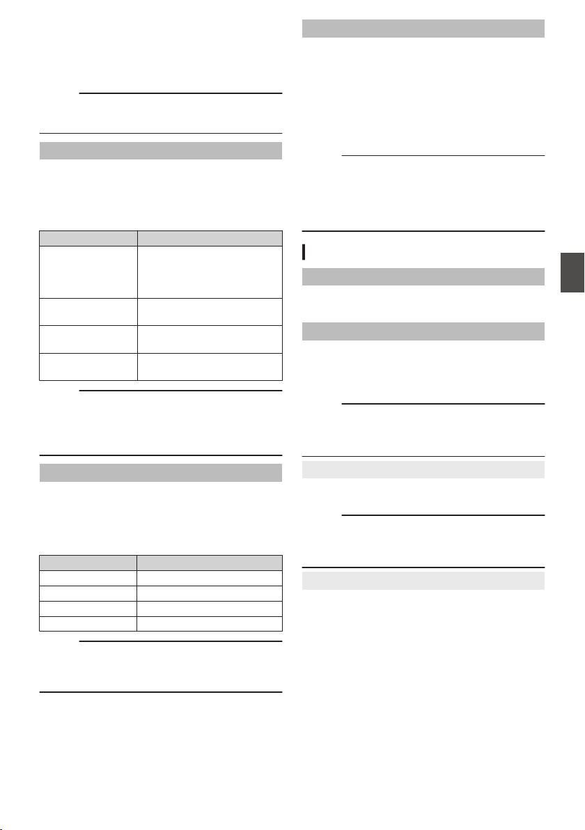
o
FEC Matrix 0
For setting the amount of FEC (Forward Error
Correction) overhead for configuring
SMPTE2022-1.
(A P215 [Setting the FEC Matrix 0] )
Memo :
0
This item is selectable only when [SMPTE
2022-1 FEC] is set to “On”.
Resolution
For setting the resolution of the video image during
live distribution.
The available options vary according to the settings
for [WResolution] and [WFrame Rate] under
[Record Format].
W Resolution
Setting Value
1920x1080 1920x1080, 1280x720,
640x360 2,
720x480 2 (U model)
720x576 2 (E model)
1280x720 1280x720,
640x360 2
720x480 2 (U
model)
720x480 2
720x576 2 (E
model)
720x576 2
Memo :
0
The setting cannot be changed during live
streaming (when [Live Streaming] set to “On”).
0
The Aspect
Ratio for the live streaming image is
fixed to “16:9”.
Frame Rate
For setting the frame rate of the video image during
live distribution.
The options vary according to the settings of [Live
Streaming Set] B [Resolution] and the [WFrame
Rate] settings under [Record Format].
W Frame Rate
Setting Value
60p, 60i 60p, 60i, 30p
50p, 50i 50p, 50i, 25p
30p 30p
25p 25p
Memo :
0
The setting cannot be changed during live
streaming (when live streaming is configured to
“On”).
Bit Rate
For setting the encode bitrate of the video image
during live distribution.
The selectable options vary according to the
settings in [Live Streaming Set] B [Resolution] and
[Bit Rate].
For details on the settings, please refer to
[Distributable [Record Format] and [Live Streaming
Set] Combinations] (A P 212).
Memo :
0
The setting cannot be changed during live
streaming (when [Live Streaming] set to “On”).
0
Depending on the type of network adapter used
and the connection, images and audio sound
during live streaming may be choppy.
Return over IP Item 0
Return over IP
For configuring Return over IP to On/Off.
[Setting Values: On, ROff]
Server
For selecting the source server for sending out
Return over IP audio/video.
[Setting Values: RServer1, Server2, Server3,
Server4]
Memo :
0
The setting cannot be changed while Return
over IP is operating (when [Return over IP] is set
to “On”).
9
Return Server
For configuring the source server for sending out
Return over IP audio/video.
Memo :
0
The setting cannot be changed while Return
over IP is operating (when [Return over IP] is set
to “On”).
9
Server1, Server2, Server3, Server4
* The name that is set in [Alias] is displayed
individually.
Network Menu
143
Menu Display and Detailed Settings

o
Alias
For setting a name to distinguish the settings of this
camera.
The name set in this item will be displayed in the
[Server] options.
*1 The default value is “Server1/Server2/
Server3/Server4”.
*2 You can enter up to 31 characters and ASCII
characters.
o
Type
For configuring the system for transferring video
and audio to be distributed.
[Setting Values: RRTSP/RTP, ZIXI o, Icecast]
Memo :
0
Operates as IFB when the setting is configured
to “Icecast”.
0
Use transmission devices that are compatible
with the respective transfer systems.
0
To use the “ZIXI” setting, a dedicated server is
needed separately.
0
The following items that can be set vary
depending on the setting of this item.
o
Protocol
For configuring the protocol of the video/audio
source server to be connected.
[Setting Values: RUDP, TCP]
Memo :
0
This item is selectable only when [Type] is set to
“RTSP/RTP”.
o
Source Address
For configuring details such as the host name and
IP address of the video/audio transmission source.
There is no default value (blank).
* You can enter up to 191 characters and ASCII
characters.
o
Source Port
Enter the network port number of the video/audio
transmission source using an integer between 1
and 65535.
The default value is
“554” when [Type] is set to
“RTSP/RTP”, “2077” when it is set to “ZIXI”, and
“5000” when it is set to Icecast.
Memo :
0
When [Type] is set to “RTSP/RTP”, only even
numbers from 2 to 65530 can be specified for
the port number.
o
Stream ID
For configuring the stream ID registered on the
video/audio transmission source.
There is no default value (blank).
* Enter not more than 63 characters.
Memo :
0
This item is available for setting when [Type] is
set to “RTSP/RTP” or “ZIXI”.
o
Username
For setting the user name.
There is no default value (blank).
* Enter not more than 63 characters.
Memo :
0
This item is selectable only when [Type] is set to
“RTSP/RTP”.
o
Password
For setting the password.
There is no default value (blank).
* You can enter up to 31 characters when [Type]
is set to “RTSP/RTP”.
* You can enter up to 127 characters when [Type]
is set to “ZIXI”.
Memo :
0
This item is available for setting when [Type] is
set to “RTSP/RTP” or “ZIXI”.
o
Name
For configuring the name.
The default value is “HC900”.
* Enter not more than 31 characters.
Memo :
0
This item is selectable only when [Type] is set to
“ZIXI”.
o
Latency
For setting the latency mode.
[Setting Values: Medium, RMinimum, Off]
Memo :
0
This item is selectable only when [Type] is set to
“ZIXI”.
o
Mountpoint
Enter the mountpoint (character string for
identifying a stream) for streaming servers that
support multiple streams.
There is no default value (blank).
* Enter not more than 63 characters.
Memo :
0
This item is selectable only when [Type] is set to
“Icecast”.
144
Network Menu
Menu Display and Detailed Settings

Web Item
Web Access
To access via a web browser, set to
“On
”.
[Setting Values: ROn, Off]
Camera Name
For setting the name to be displayed on the web
browser. Enter not more than 8 characters using
the software keyboard.
(Default value: HC900)
Username
For setting the user name. Enter not more than 31
characters using the software keyboard.
(Default value: jvc)
Password
Changes the password for accessing via a web
browser.
The current password is displayed. Enter a new
password directly.
Enter not more than 31 characters using the
software keyboard.
(Default value: random alphanumeric value that
varies with each model)
Port
For configuring the port number during access to a
web page from an external source.
Memo :
0
Enter the name using the software keyboard.
0
Enter an integer between 1 and 65535. (Default
value: 80)
0
To configure the setting to a number other than
the default value, specify the number of an
unused port.
0
For more details, please consult the
administrator of the network in use.
Metadata Server Item
Meta-FTP1, Meta-FTP2, Meta-FTP3, Meta-
FTP4
*
The name that is set in
[Alias] is displayed
individually.
o
Alias
For setting a name to distinguish the settings of this
camera.
The name set in this item will be displayed in the
[Import Metadata] options.
* Enter not more than 31 characters.
o
Protocol
For setting the protocol of the FTP server to be
connected.
0
FTP:
Protocol that does not encrypt the incoming and
outgoing data.
0
SFTP:
Protocol that encrypts incoming and outgoing
data using SSH.
0
FTPS:
Protocol that encrypts incoming and outgoing
data using SSL or TLS. It uses an implicit mode
(starts encrypted communication once
connection starts).
0
FTPES:
Protocol that encrypts incoming and outgoing
data using SSL or TLS. It uses an explicit mode
(starts encrypted communication after
permission is granted).
[Setting Values: RFTP, SFTP, FTPS, FTPES]
o
Server
For setting the server name (“mystation.com”, etc.)
or the IP address (“192.168.0.1”, etc.) of the FTP
server.
* Enter not more than 127 characters using
single-byte alphanumeric characters (a to z, 0 to
9), single-byte hyphen [-], or dot [.].
o
Port
Enter the FTP server port number to use using an
integer between 1 and 65535.
The default value varies with the protocol setting.
(FTP: 21, SFTP: 22, FTPS: 990, FTPES: 21)
o
File Path
Enter the path name for the metadata file (“/pub/
meta.xml”, “/home/user/meta2.xml”, etc.)
0
Enter not more than 127 characters.
Network Menu
145
Menu Display and Detailed Settings

o
Username
Enter the user name for connecting to the FTP
server.
* Enter not more than 31 characters.
o
Password
Enter the password for connecting to the FTP
server.
*
Enter not more than 31 characters.
o
PASV Mode
For setting whether to set the communication mode
used for file transfer to the passive mode.
Set to
“On” if the camera is inside a firewall, and a
connection from the FTP server to the camera
cannot be established.
[Setting Values: On, ROff]
Memo :
0
When [
Protocol
] is set to “SFTP”, this item
appears as “---” and cannot be selected.
Upload Item 0
Upload
For configuring the method for uploading to the
FTP server.
0
Auto:
Select this option for automatic FTP transfer.
FTP transfer starts when [Automatic upload] is
configured to “On”.
0
Manual:
Select this option for manual FTP transfer from
the Media mode.
[Setting Values: RAuto, Manual]
Auto Upload
When [Upload] is configured to “Auto”, FTP
transfer starts automatically when the setting is
configured to “On”.
[Setting Values: On, ROff]
Memo :
0
This is fixed at “Off” when [System] is set to
“High-Speed”2.
9
Slot
For selecting the recording media slot to enable
automatic upload.
[Setting Values: RA, B]
9
Cellular
For
configuring whether to enable connection via a
USB cellular adapter.
[Setting Values: Enable, RDisable]
9
Server
For
configuring the server for uploading to the FTP
server.
[Setting Values: RClip-FTP1, Clip-FTP2, Clip-
FTP3, Clip-FTP4]
Clip Server
Clip-FTP1, Clip-FTP2, Clip-FTP3, Clip-FTP4
* The name that is set in [Alias] is displayed
individually.
o
Alias
For setting a name to distinguish the settings of this
camera.
The name set in this item will appear on the [FTP
Upload] action screen of the thumbnail display.
* Enter not more than 31 characters.
o
Protocol
For setting the protocol of the FTP server to be
connected.
0
FTP:
Protocol that does not encrypt the incoming and
outgoing data.
0
SFTP:
Protocol that encrypts incoming and outgoing
data using SSH.
0
FTPS:
Protocol that encrypts incoming and outgoing
data using SSL or TLS. It uses an implicit mode
(starts encrypted communication once
connection starts).
0
FTPES:
Protocol that encrypts incoming and outgoing
data using SSL or TLS. It uses an explicit mode
(starts encrypted communication after
permission is granted).
0
ZIXI:
Enables stable transmission by reducing jitter
and packet loss significantly through
communicating via a relay server.
[Setting Values: RFTP, SFTP, FTPS, FTPES, ZIXI]
Memo :
0
To use the
“ZIXI” setting, a dedicated server is
needed separately.
0
If “ZIXI” is set, the resume function is enabled.
146
Network Menu
Menu Display and Detailed Settings

o
Server
For setting the server name (“mystation.com”, etc.)
or the IP address (“192.168.0.1”, etc.) of the FTP
server.
* Enter not more than 127 characters using
single-byte alphanumeric characters (a to z, 0 to
9), single-byte hyphen [-], or dot [.].
o
Port
Enter the FTP server port number to use using an
integer between 1 and 65535.
The default value varies with the protocol setting.
(FTP: 21, SFTP: 22, FTPS: 990, FTPES: 21, ZIXI:
2088)
o
Dir. Path
Enter the path name for the directory to upload to
(“/pub”, “/home/user”, etc.)
* Enter not more than 127 characters.
o
Username
Enter the user name for connecting to the FTP
server.
*
Enter not more than 31 characters.
o
Stream ID
For configuring the stream ID that is registered at
the distribution destination.
The default value varies with the product model.
*
Enter not more than 63 characters.
Memo :
0
This item is selectable only when [Type] is set to
“ZIXI”.
o
Password
Enter the password for connecting to the FTP
server.
* Enter not more than 31 characters. Enter not
more than 127 characters for ZIXI setting.
o
PASV Mode
For setting whether to set the communication mode
used for file transfer to the passive mode.
Set to
“On” if the camera is inside a firewall, and a
connection from the FTP server to the camera
cannot be established.
[Setting Values: On, ROff]
Memo :
0
When [Protocol] is set to “SFTP”, this item
appears as “---” and cannot be selected.
Network Menu
147
Menu Display and Detailed Settings

System Menu
This menu screen allows system-related settings.
For configuring recording settings, formatting and
restoration of a recording media, tally lamp setting,
date/time, time zone and other settings.
It can also be used to reset the menu settings to
their default values.
Record Set...
For specifying recorded video-related settings.
(A P151 [Record Set Item] )
Media
9
Format Media
For formatting (initializing) a recording media.
Select a card slot, select [Format] from [Cancel]/
[Format], and press the [STATUS/SET] button (R)
to format (initialize) the card.
(A P50 [Formatting (Initializing) SD Cards] )
9
Restore Media
For restoring a recording media.
Select a card slot, and press the
[STATUS/SET]
button (R) to restore the SD card.
(A P51 [Restoring the SD Card] )
Memo :
0
This item appears only when the recording
media needs to be restored. However, it is not
selectable when recording in Camera mode and
during Clip Review.
Setup File
This allows you to save the menu settings as well
as the performance results of shutter speed and
AWB.
It is useful to save settings according to different
shooting conditions.
9
Load File...
Loads the settings.
(A P
177 [Loading a Setup File] )
9
Store File...
Saves the settings.
(A P
176 [Saving Setup Files] )
9
Delete File...
Deletes the configured file.
(A P
178 [Deleting Setup Files] )
Tally System
For setting the display conditions of the tally lamp
(front and back) on the camera recorder.
0
Internal:
Displays mainly the status of the camera
recorder.
0
Studio:
Displays the TALLY IN/PREVIEW IN signals
from an external device, such as a remote
control unit.
[Setting Values: RInternal, Studio]
Front Tally/Back Tally
For configuring how the front and back tally lamps
on this camera recorder are illuminated when [Tally
System] is set to “Internal” and while recording is in
progress, when a remaining level warning is
displayed or during live streaming.
0
Rec/Live Streaming:
Lights up during recording or live streaming.
0
Live Streaming:
Lights up during live streaming. Does not light
up during recording.
0
Rec:
Lights up during recording.
[Setting Values: Rec/Live Streaming, Live
Streaming, RRec]
Memo :
0
When [Tally System] is set to “Studio”, this item
appears as “---” and selection is disabled.
GPS u v
For setting the GPS function to On or Off (power
on/off).
[Setting Values: On, ROff]
Memo :
0
When [A/V Set] B [Video Set] B [SDI OUT1
Res.] is set to “1080p”, configuring [System] B
[GPS] to “On” changes the setting to “1080i”.
u v
148
System Menu
Menu Display and Detailed Settings

Battery 0
For configuring the warning voltage or warning
level (%) according to the battery specifications
and condition of use.
9
Type
2
For configuring the battery warning using voltage
or remaining level (%).
[Setting Values: Capacity%, RVoltage]
Memo :
0
For batteries where information on the
remaining level cannot be acquired, the status
will be the same as when “Voltage” is selected
even when “Capacity%” is selected. To find out
whether information on the remaining level can
be obtained for the battery, check the remaining
battery level icon on the display screen.
9
Near End (V)
0
Outputs a warning sound when the voltage falls
below the preset level.
[Setting value: 12.1 V to 14.0 V (R13.1 V)]
Memo :
0
This
cannot be configured to a value that is lower
than the setting of [End (V)].
9
End (V)
0
Outputs
a warning sound upon reaching the preset
voltage, and turns off the power automatically when
the voltage falls below the preset level.
[Setting value: 12.0 V to 13.9 V (R12.8 V)]
Memo :
0
This cannot be configured to a value that is
higher than the setting of [
Near End (V)].
9
Near End (%)
2
Outputs a warning sound when the voltage falls
below the preset level (%).
[Setting Values: 10 %, 15 %, R20 %, 25 %, 30 %]
Memo :
0
This cannot be configured to a value that is lower
than the setting of [End (%)].
0
A warning sound is also output when the voltage
reaches 12.5 V or lower.
9
End (%)
2
Outputs
a warning sound upon reaching the preset
level (%), and turns off the power automatically
when the remaining level falls below the preset
level.
[Setting Values: 1 %, 5 %, R10 %, 15 %, 20 %]
Memo :
0
This cannot be configured to a value that is
higher than the setting of [Near End (%)].
0
A warning sound is also output when the voltage
reaches 12.0 V, and the power will turn off
automatically when the voltage reaches 11.9 V
or lower.
Language
Switches between languages in the menu screen.
[Setting Values: REnglish, Français, Español] (U
model)
[Setting Values: REnglish, Français, Deutsch,
Italiano, Español, Türkçe] (E model)
Reset All
Resets all menu settings.
Memo :
0
[Date/Time] and [Time Zone] cannot be reset.
(A P149 [ Date/Time ] )
(A P150 [ Time Zone ] )
0
This item is not selectable when recording in
Camera mode, during Clip Review, during live
streaming and in Media mode.
Date/Time
For setting the year, month, day, hour, and minute.
Memo :
0
The display order of the date (year, month, day)
follows the setting in [Display Settings] B [Date
Style]. However, the 24-hour format is used for
the hour display regardless of the [Time Style]
setting.
(A P150
[ Time Style ] )
0
If the signal reception for GPS satellites allows
date and time to be set based on the GPS
information, you can set the time obtained from
the GPS satellite by pressing the [USER1]
button.
The [USER1] button is grayed out if information
for setting the date and time cannot be acquired
from the GPS satellite. u v
System Menu
149
Menu Display and Detailed Settings

Date Style
For setting the date display sequence for display
on the LCD monitor and viewfinder screen as well
as for time stamp recording.
Display examples of the setting values are as
follows.
0
DMY2: 30 Jun 2018
0
DMY1: 30-06-2018
0
MDY2: Jun 30, 2018
0
MDY1: 06-30-2018
0
YMD: 2018-06-30
[Setting Values: DMY2, DMY1, MDY1, MDY2,
YMD]
(Default values: MDY2 (U model), DMY1 (E
model))
Time Style
For setting the time display for display on the LCD
monitor and viewfinder screen as well as for time
stamp recording.
[Setting Values: R24hour, 12hour]
Time Zone
For setting the UTC time difference in units of 30
minutes.
[Setting Values: UTC-12:00-UTC-00:30, UTC,
UTC+00:30-UTC+14:00 (in 30 min increments)]
(Default values: UTC-05:00 (U model), UTC (E
model))
Memo :
0
If [Date/Time
] is already set, the [Date/Time]
item is automatically adjusted when [Time
Zone] is altered.
Reserved
For setting the additional function to “On” or “Off”.
9
Reserved 1 to Reserved 16
Normally set to
“Off”.
[Setting Values: On, ROff]
System Information
9
Version
Displays
the version of the camera in the upper row
and the version of the dedicated viewfinder in the
lower row.
Display : 0000-0000
00-00-00
Memo :
0
The lower row is displayed only when a
viewfinder (supplied u v or separately
sold w x) is connected .
9
Fan Hour
For displaying the usage time of the internal fan.
Memo :
0
Under normal environment, dust will
accumulate on the internal fan when the camera
recorder is used over a long period. Dust may
enter the camera recorder especially if it is used
outdoors. This may affect the image and sound
quality of the camera recorder. Check and
replace the fan after every 9000 hours
(suggested guideline).
9
Open Source License
Displays the license for the open source software
used by this camera recorder.
150
System Menu
Menu Display and Detailed Settings

Record Set Item
Record Format
After setting of all items in the
[Record Format
]
menu is complete, select [Set] at the bottom of the
screen to apply the new settings on the camera
recorder and switch the recording format. A
“Please Wait...” message appears during
switching.
9
System
For selecting a system definition.
0
HD:
Records in “HD” (High Definition) quality for both
slots A and B.
0
SD2:
Records in “SD” (Standard Definition) quality for
both slots A and B.
0
HD+Web2:
Records in “HD” (high definition) for slot A, and
in resolution suitable for web distribution for slot
B.
0
HD(SDI In):
Records the HD SDI video of the device
connected to the [HD/SD SDI IN] terminal in
“HD” to both slot A and slot B.
0
SD(SDI In)2:
Records the SD SDI video of the device
connected to the
[HD/SD SDI IN] terminal in
“SD” to both slot A and slot B.
0
High-Speed2:
Records slow motion videos in
“HD” (High
Definition) for both slot A and slot B.
[Setting Values: RHD, SD2, HD+Web2,
HD(SDI In), SD(SDI In)2, High-Speed2]
Caution :
0
The selectable options for the [WFormat],
[WResolution], [WFrame Rate], [WBit Rate]
[WAudio], [YFormat], [YResolution], [YFrame
Rate], [YBit Rate] and [YAudio] settings vary
depending on the setting of this item.
0
When [System] B [Record Set] B [Record
Format] B [System] is configured to “High-
Speed”2, network cannot be used via
wireless LAN u v or the [HOST] terminal
(USB). Configure as follows in this case.
0
Set
[Network] B [Connection Setup] B [USB/
Int. WLAN] to “Off”. u v
0
Unplug the USB network adapter
Note that camera operation will come to an
emergency
stop and the power will turn off if the
above steps are not performed.
File data may be damaged if this happens while
recording is in progress.
9
W Format
For
selecting the format of the file to be recorded to
the SD card in slot A.
0
QuickTime(MPEG2):
QuickTime file format (.MOV)
0
MXF(MPEG2)0:
MXF (material exchange format)
0
QuickTime(H.264):
QuickTime file format (.MOV)
0
Exchange0: (U model only)
Sports Video Interop Group format
0
MP4 (H.264)0: (E model only)
MP4 file format
[Setting Values: QuickTime(MPEG2),
MXF(MPEG2), RQuickTime(H.264), Exchange]
(U model only)
[Setting Values: QuickTime(MPEG2),
MXF(MPEG2), RQuickTime(H.264), MP4 (H.
264)](E model only)
Memo :
0
When [System] is set to “SD”2 or “SD(SDI
In)”2, this item is fixed at “QuickTime(H.
264)”.
0
When [System
] is set to “HD+Web”, this item is
fixed at “QuickTime(H.264)”. 2
0
When
[System] is set to “High-Speed”, this item
is fixed at “QuickTime(H.264)”. 2
0
Exchange (U model) and MP4 (H.264) (E
model) are selectable only when
[System] is
configured to “HD” or “HD(SDI In)”.
0
Exchange format is used under license from
Sports Video Interoperability Group, Inc..
System Menu
151
Menu Display and Detailed Settings

9
W Resolution
For selecting the image size to be recorded to the
SD card in slot A. (Horizontal x vertical)
The available options vary according to the
[System] and [WFormat] settings.
0
When [System] is set to “
HD” or “HD(SDI In)”,
and [WFormat] is set to “QuickTime(MPEG2)” or
“MXF(MPEG2)”0:
[Setting Values: R1920x1080, 1440x1080,
1280x720]
0
When [
System] is set to “HD” or “HD(SDI In)”,
and [WFormat] is set to “QuickTime(H.264)”:
[Setting Values: 1920x1080, 1280x720]
0
When [System
] is set to “HD” or “HD(SDI In)”,
and [WFormat] is set to “Exchange” (U model
only):
[Setting Values: 1920x1080, 1280x720]
0
When [System] is set to
“HD” or “HD(SDI In)”,
and [WFormat] is set to “MP4(H.264)” (E model
only):
[Setting Values: 1920x1080, 1280x720]
0
When [System] is set to
“HD+Web”2:
[Setting Values: 1920x1080, 1280x720]
0
When [System] is set to “High-Speed”2:
Fixed at “1920x1080”.
0
When
[System] is set to “SD”2 or “SD(SDI
In)”2:
Fixed at either “720x480” or “720x576”.
Memo :
0
The selectable values of [WFrame Rate] and
[WBit Rate] vary according to the setting of this
item.
9
W Frame Rate
For selecting the frame rate to be recorded to the
SD card in slot A.
The available options vary according to the settings
for [System], [WResolution], and [WFormat].
0
When [System] is set to “HD” or “HD(SDI In)”,
[WFormat] is set to “QuickTime(MPEG2)” or
“MXF(MPEG2)”0, and [WResolution] is
set to “1920x1080”:
[Setting Values: 60i, 50i, 30p, 25p]
0
When [System
] is set to “HD”, “HD(SDI In)” or
“HD+Web”2, [WFormat] is set to
“QuickTime(H.264)”, and [WResolution] is set to
“1920x1080”:
[Setting Values: 60p, 60i, 50p, 50i, 30p, 25p,
24p2]
0
When [System]
is set to “HD” or “HD(SDI In)” and
[WResolution] is set to “1440x1080”:
[Setting Values: 60i, 50i]
0
When [System] is set to
“HD”, “HD(SDI In)” or
“HD+Web”2 and [WResolution] is set to
“1280x720”:
[Setting Values: 60p, 50p]
0
When [System] is set to
“HD” or “HD(SDI In)”,
and [WFormat] to “Exchange”0:
Fixed at “60p”. (U model only)
0
When [System] is set to
“HD” or “HD(SDI In)”,
and [WFormat] to “MP4(H.264)”0:
Fixed at “60p” or “50p”.
0
When
[System] is set to “SD”2 or “SD(SDI
In)”2:
Fixed at either “60i” or “50i”.
0
When [System] is configured to “High-
Speed”2:
[Setting Values: 120/60p, 100/50p, 120/30p,
100/25p, 120/24p]
Memo :
0
When [System] is configured to “HD(SDI In)”,
“30p”/“25p”/“24p”2 under [WFrame Rate]
cannot be selected.
152
System Menu
Menu Display and Detailed Settings
9
W Bit Rate
For selecting the bit rate to be recorded to the SD
card in slot A.
The available options vary according to the settings
for [System], [WResolution], and [WFormat].
0
When [System] is set to “HD” or “HD(SDI In)”,
[WFormat] is set to “QuickTime(MPEG2)” or
“MXF(MPEG2)”0, and [WResolution] is
set to “1440x1080”:
[Setting Values: 35M (HQ), 25M (SP)]
* When
[WResolution] is set to a setting other than
“1440x1080”, it is fixed at “35M (HQ)”.
0
When [System] is set to “HD”, “HD(SDI In)” or
“HD+Web”2 and [WFormat] is set to
“QuickTime(H.264)”:
0
When [WResolution] is set to
“1920x1080”,
and [WFrame Rate] is set to “60p” or “50p”:
[Setting Values:
70M (XHQ)0,
50M (XHQ), 35M (UHQ)]
0
When [WResolution] is set to “1920x1080”,
and [WFrame Rate] to “60i”/“50i”/“30p”/“25p”/
“24p”2:
[Setting Values:
50M (XHQ), 50M
(XHQ), 35M (UHQ)]
0
When [WResolution] is set to “1280x720”:
[Setting Values:
50M (XHQ), 35M
(UHQ)]
0
When [System] is set to “HD” or “HD(SDI In)” and
[WFormat] is set to “Exchange”0 or
“MP4(H.264)”0:
0
When [WResolution] is set to
“1920x1080”:
Fixed at “12M(LP)”.
0
When [WResolution] is set to “1280x720
”:
Fixed at “8M(LP)”.
0
When
[System] is set to “SD”2 or “SD(SDI
In)”2:
Fixed at 8M (HQ).
0
When [System] is set to
“High-Speed”2:
0
When [WFrame Rate] is set to “120/60p” or
“100/50p”
[Setting Values:
70M (XHQ),
50M (XHQ), 50M (UHQ)]
0
When [WFrame Rate] is configured to a
setting other than “120/60p” and “100/50p”
[Setting Values:
50M (XHQ), 50M
(XHQ), 35M (UHQ)]
Memo :
0
When [System] is configured to “HD(SDI In)”,
“30p”/“25p”/“24p”2 under [WFrame Rate]
cannot be selected.
9
W Audio
For selecting the audio to be recorded to slot A (2ch
or 4ch). The selectable options vary according to
the settings in [WFormat] or [WBit Rate].
0
When [WBit Rate] is configured to a setting other
than “
70M (XHQ)”0 and
“
50M (XHQ)”:
[Setting Values: R4CH 16 bit, 2CH 16 bit]
0
When [WBit Rate] is set to “
70M
(XHQ)”0 or “
50M (XHQ)”:
[Setting Values: R4CH 24 bit, 2CH 24 bit]
Memo :
0
When [WFormat] is configured to
“Exchange”0 (U model) or
“MP4(H.264)”0 (E model), the setting is
fixed at “2CH”.
0
When [System] is configured to “High-
Speed”2, the setting is fixed at
“2CH”.
9
Y Format
For selecting the format of the file to be recorded to
the SD card in slot B when [System] is configured
to “HD+Web”2.
This is fixed at QuickTime (H.264).
Memo :
0
When [System] is set to other than “HD
+Web”2, this item is fixed at the same
setting as [WFormat].
9
Y Resolution
For selecting the size of the image to be recorded
to
the SD card in slot B when [System] is configured
to “HD+Web”2. (Horizontal x vertical)
0
When [System] is set to “HD+Web
”2:
0
When [WFrame Rate] is configured to “60p”/
“60i”/“30p”
[Setting Values: 960x540, 720x480,
480x270]
0
When [WFrame Rate] is configured to “50p”/
“50i”/“25p”
[Setting Values: 960x540, 720x576,
480x270]
0
When [WFrame Rate] is configured to “24p”
[Setting Values: 960x540, 480x270]
Memo :
0
When [System] is set to other than “HD
+Web”2, this item is fixed at the same
setting as [WResolution].
System Menu
153
Menu Display and Detailed Settings

9
Y Frame Rate
The frame rate of the image to be recorded to the
SD card in slot B is fixed when [System] is set to
“HD+Web”2.
The value fixed varies according to the settings for
[WFrame Rate].
0
Fixed
at “60i”, “50i”, “30p”, “25p” or “24p”2.
Memo :
0
When [System] is set to other than “HD
+Web”2, this item is fixed at the same
setting as [WFrame Rate].
9
Y Bit Rate
The bit rate of the image to be recorded to the SD
card in slot B is fixed when [System] is set to “HD
+Web”2.
The value fixed varies according to the settings for
[YResolution].
0
“3M(HQ)”
when [YResolution] is configured
to “960x540”
0
“1.2M(LP)”
when [YResolution] is configured
to “480x270”
0
“8M(HQ)
” when [YResolution] is configured
to “720x480” or “720x576”
Memo :
0
When [System] is set to other than “HD
+Web”2, this item is fixed at the same
setting as [WBit Rate].
9
Y Audio
The
audio (2ch/4ch) to be recorded to slot B is the
same as the audio to be recorded to slot A.
9
SD Aspect
2
For setting the aspect ratio of the image when
[System] is set to
“SD” or “SD(SDI In)”.
[Setting Values: R16:9, 4:3]
Memo :
0
For conditions other than those above, this item
is fixed at “16:9”.
Rec Mode 0 1
0
For selecting the mode for recording to the
recording media.
(A P90 [Special Recording 0] )
[Setting Values: RNormal, Pre Rec0, Clip
Continuous0, Interval Rec1, Frame
Rec1]
Memo :
0
When
[Slot Mode] is set to “Backup”0, this
item is fixed at “Normal”.
0
This is fixed at
“Normal” when [System] B
[Record Format] B [System] is configured to any
of the following.
0
HD(SDI In)
0
SD(SDI In) 2
0
HD+Web 2
0
High-Speed 2
9
Pre Rec Time
0
For setting the pre-recording time when
[Rec
Mode] is set to “Pre Rec”.
[Setting Values: R5sec, 10sec, 15sec]
9
Rec Frames
1
For setting the number of frames to record when
[Rec Mode] is set to “Frame Rec” or “Interval Rec”.
[Setting Values: R1frame, 3frames, 6frames]
9
Rec Interval
1
For setting the recording time interval when [Rec
Mode] is set to
“Interval Rec”.
[Setting Values: R1sec, 2sec, 5sec, 10sec, 30sec,
1min, 2min, 5min, 10min, 30min, 1hour]
154
System Menu
Menu Display and Detailed Settings

Slot Mode
For setting the operation of the card slot.
0
Series:
Mode that activates slots A and B sequentially.
0
Dual:
Mode that activates slots A and B
simultaneously.
(A P86 [Dual Rec] )
0
Backup0: Mode that enables recording to
slot B without using the [REC] button. This item
is selectable only when [Rec Mode] is set to
“Normal”. Record, start and stop operations can
be controlled from the [Backup Rec] menu or
using the user button that is assigned with
“Backup Trig”.
(A P
88 [Backup Rec 0] )
[Setting Values: RSeries, Dual, Backup0]
Memo :
0
When this is configured to “Series” and
recordable media is inserted into slot A or slot B
or both the slots, pressing the [REC] button
starts recording only to the card in the selected
slot (active slot).
0
When
this is configured to “Dual” and recordable
media are inserted into both slots A and B,
pressing the [REC] button starts simultaneous
recording to the cards in both slots.
0
When [System] is configured to “HD
+Web”2, “---” is displayed.
9
Backup Rec
0
For starting/stopping backup recording with [REC]/
[STBY].
This item is selectable only when [Slot Mode] is set
to “Backup”.
Memo :
0
When recording is stopped due to no remaining
space on the media, etc., this item is fixed at
“STOP” and cannot be selected.
4GB File Spanning(SDXC)
A recording file is automatically split when the size
exceeds 4 GB, but if an SDXC card is used, you
can record clips larger than 4 GB by setting this
option to “Off”. (Up to a maximum of 64 GB or 4
hours)
0
On:
Splits a file when it exceeds 4 GB or 30 minutes.
0
Off:
Splits a file when it exceeds 64 GB or 4 hours.
[Setting Values: ROn, Off]
Memo :
0
This option is only valid if the SD card used for
recording is of the SDXC format.
0
During simultaneous recording, such as Dual
Rec and backup recording0, this option is
valid only when the SD cards in slots A and B
are of the SDXC format.
LPCM (QuickTime)
For setting the audio recording format of
QuickTime.
[Setting Values: Dual Mono, RStereo]
System Menu
155
Menu Display and Detailed Settings

Time Stamp
For setting whether to display shooting date/time
information in the recorded video.
[Setting Values: On, ROff]
Memo :
0
The date/time display style can be changed in
[Date Style]/[Time Style].
(A P150 [ Date Style ] )
(A P150 [ Time Style ] )
0
When [System] is set to “High-Speed”2,
this item is fixed at “Off”.
Clip Set
9
Clip Name Prefix
For configuring the first four characters of the name
of the clip file to be recorded to the recording media.
Enter any of the 36 characters including alphabets
(upper case) and numbers (0 to 9) using the
software keyboard.
(A P107 [Text Input with Software Keyboard] )
[Setting Values: xxxG] (The default value of xxx is
the last three digits of the serial number.)
9
Reset Clip Number
For assigning a new number (Clip Number) by
resetting it (0001).
Select [Reset]
and
press the [STATUS/SET] button
(R) to reset the number.
If there are other clips on the recording media, it will
be assigned with the smallest available number.
0
Example:
If the [Clip Name Prefix] is “ABCD” and
“ABCD0001” already exists on the recording
media, “ABCD0002” will be assigned.
Clear Planning Metadata
Erases the planning metadata downloaded from
the FTP server.
This item also deletes the metadata loaded using
the setup files (“User File”/“All File”).
156
System Menu
Menu Display and Detailed Settings
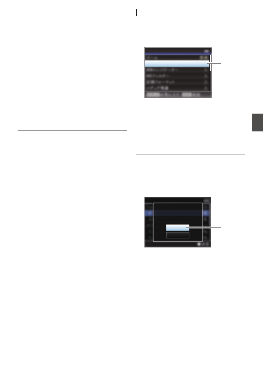
Adding/Editing
Frequently Used Menu
Items (Favorites Menu)
You can select and add/edit frequently used menu
items freely to create a personal menu screen
(Favorites Menu).
Memo :
0
[Favorites Menu] is only enabled in the Camera
mode. [Favorites Menu] remains unchanged
even when the recording format changes.
0
Up to 20 menu items can be added.
0
Added
items in [Favorites Menu] will not be reset
even when [Main Menu] B [Reset All] is
executed.
0
Long descriptive names may be displayed for
the menu items in
[Favorites Menu] to enable
better understanding.
Adding Menu Items to Favorites Menu
1
Press the [MENU/THUMB] button to open
the [Main Menu] screen.
2
Select the menu or submenu item to add.
.
Focus
Display Settings
Meter
2
Memo :
0
Adding items to [Favorites Menu] cannot be
performed in the following cases. [USER1
Add] is displayed in gray in the operation guide.
0
Selected item is already added to
[Favorites
Menu].
0
Number
of menu items that can be added (20
items) is exceeded.
3
Press the [USER1] button.
A screen to confirm the addition appears.
4
Select [Add] and press the Set button (
R).
The selected menu item is added to [Favorites
Menu].
.
4
Cancel
Add
Focus
Add to Favorites Menu?
Adding/Editing Frequently Used Menu Items (Favorites Menu)
157
Menu Display and Detailed Settings
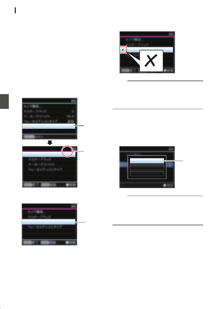
Editing Favorites Menu
You can delete or change the order of the items
added to [Favorites Menu].
Deleting Items from [Favorites Menu]
1
Open the [Favorites Menu] screen.
A
Press the [MENU/THUMB] button to
open the [Main Menu] screen.
B
Press the [DISPLAY] button or press and
hold down the [MENU/THUMB] button to
open the [Favorites Menu] screen.
2
Select [Edit Favorites] and press the Set
button (
R) or crossed-shaped button (I).
The header turns magenta and the editing
mode is activated.
.
2
Header
(Magenta)
Camera Function...
Edit Favorites
Edit Favorites
Favorites Menu
3
Select the menu or submenu item to delete.
.
3
Aspect Marker
Edit Favorites
4
Press the [USER2] button.
A delete mark (b) appears at the beginning of
the menu item.
.
Aspect Marker
Edit Favorites
Memo :
0
When the [USER2] button is pressed again
while the menu item with the delete mark (b) is
selected, the menu item will be excluded from
the items to be deleted and the delete mark (b)
disappears.
5
Press the [USER1] button.
The option menu to exit the [Favorites Menu]
editing mode appears.
6
Select [Save & Exit] and press the Set
button (
R).
.
6
Cancel
Exit without Saving
Save & Exit
Edit Favorites
Memo :
0
Deletion is not complete until the changes are
saved with [Save & Exit].
0
To exit the editing mode without deleting any
items, select [Exit without Saving].
0
To return to the editing mode, select [Cancel].
158
Adding/Editing Frequently Used Menu Items (Favorites Menu)
Menu Display and Detailed Settings
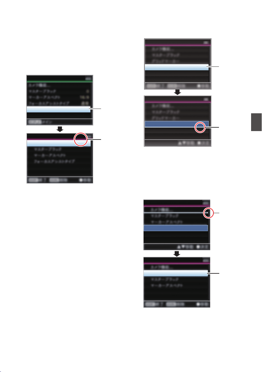
Changing the Order of Items in [Favorites
Menu]
1
Open the [Favorites Menu] screen.
Press the [MENU/THUMB] button to open the
[Favorites Menu] screen.
2
Select [Edit Favorites] and press the Set
button (
R) or crossed-shaped button (I).
The header turns magenta and the editing
mode is activated.
.
2
Header
(Magenta)
Camera Function...
Edit Favorites
Edit Favorites
Favorites Menu
3
Select the menu or submenu item to move
and press the Set button (
R).
The moving mode is activated and a position
selection bar for the move appears.
.
Edit Favorites
Edit Favorites
TC/UB
TC/UB
3
Position
Selection
Bar
4
Select the position to move to with the
cross-shaped button (
JK).
Move the position selection bar with the cross-
shaped button (JK) and select a position to
move to.
5
Press the Set button (
R).
The selected item moves to the new position.
.
5
4
TC/UB
TC/UB
Edit Favorites
Edit Favorites
Adding/Editing Frequently Used Menu Items (Favorites Menu)
159
Menu Display and Detailed Settings

6
Press the [USER1] button.
The option menu to exit the [Favorites Menu]
editing mode appears.
7
Select [Save & Exit] and press the Set
button (
R).
.
7
Cancel
Exit without Saving
Save & Exit
Edit Favorites
Memo :
0
Moving is not complete until the changes are
saved with [Save & Exit].
0
To exit the editing mode without saving any
changes, select [Exit without Saving]
.
0
To return to the editing mode, select [Cancel].
160
Adding/Editing Frequently Used Menu Items (Favorites Menu)
Menu Display and Detailed Settings
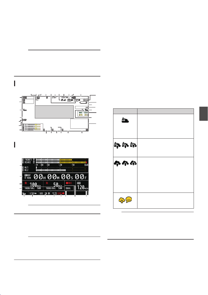
Display Screen in Camera
Mode
When the display setting for [LCD/VF] B [Display
On/Off] is set to “Off”, the corresponding display is
hidden but it will appear for approximately 3
seconds when changes are being made.
Memo :
0
When the display screen is turned off, it will
appear only in the following cases.
0
Approximately 3 seconds when changes are
being made
0
During event display or warning display
Display Screen
.
100min
50min
282min
1
/60
F2. 8
AE
±0
ND1
/64
12 :34 : 56
ISO
102400
00: 00: 00.00
1080 /30p
SDI IN
ITU709
COMPRESS
5 . 6 f t
B 5600
K
G
L
J
B
M
N
P
T
C
D
E
F
A
IH
K
Y X
c
Q
Wdf be Z
S
R
V
a
O
U
Enlarged Display
Enlarged Display (LCD Monitor Only)
.
B
e
V
G
C X b
U
a g AZ
Memo :
0
Only the display on the LCD monitor is enlarged.
A
Voltage/Battery Power
Displays the current status of the power supply
in use.
(A P36 [Power Status Display] )
Memo :
0
Even when the display screen is turned off and
[LCD/VF] B [Display On/Off] B [Battery] is set to
“Off”, this will be displayed when there is a
warning.
B
Remaining Space on Media
Displays the remaining recording time for the
recording media in slot A and slot B separately.
W
: Currently selected slot. (White card)
W z : Write-protect switch of SD card is set.
W!INVALID : SD card cannot be read or
written to, or restored.
W!FORMAT : SD card requires
formatting.
W!RESTORE : SD card requires restoring.
W
!INCORRECT
:
0
When the SD card is not supported.
0
When an SD card lower than Class 10 is
inserted while in the XHQ mode.
W!REC INH :
0
When attempting to record more than 4
GB while a media that does not support
recording of more than 4 GB is inserted.
(A P155 [ 4GB File Spanning(SDXC) ] )
The following icons are displayed during FTP
upload.
(A P191 [Uploading a Recorded Video Clip] )
Icon Status
.
[Auto Upload] is configured to
“On” and in the standby state.
“A” is displayed at the top left
corner of the icon while in the
Auto FTP mode.
.
Auto FTP transfer is in progress.
Three images are alternately
displayed, and the arrows
become animated.
.
FTP transfer is in progress.
Three images are alternately
displayed, and the arrows
become animated. In this case,
instead of the recordable time of
the SD card, an estimated value
of the remaining transfer time is
displayed.
.
(Yellow)
Error has occurred during FTP
transfer.
Memo :
0
The displayed time is an estimate.
0
Even when the display screen is hidden and
[LCD/VF] B [Display On/Off] B [Media
Remain] is set to “Off”, this will be displayed
when there is a warning.
Display Screen in Camera Mode
161
Display/Status Screen
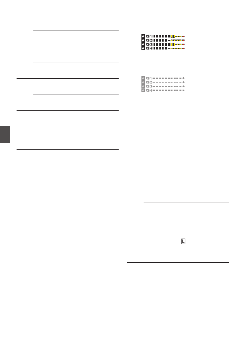
C
Operation lock
The r icon appears during operation lock.
(A P53 [Operation Lock Feature] )
Memo :
0
The s icon appears for 3 seconds after
operation lock is turned off.
D
Black Toe
Displays the Black Toe setting.
Memo :
0
The “Normal” appears for 3 seconds after
changing to Normal.
E
Skin Detail
e appears when Skin Detail is functioning.
Memo :
0
f appears for 3 seconds after Skin Detail is
turned off.
F
Color Space Display
Displays the color space.
Memo :
0
This can be configured in [Camera Process] B
[Color Space].
(A P
116 [ Color Space ] )
G
Audio Level Meter
0
Displays the audio levels for CH-1 to CH-4.
0
a appears on the screen when in the Auto
mode.
.
0
This is grayed out when in a mode that does
not support audio recording or when the
audio is not supported. The CH display is
grayed out in the enlarged display mode.
.
0
When in the enlarged display mode, the
display changes with the setting of the
[AUDIO INPUT CH1/CH2/CH3/CH4]
selection switch.
Example: During 1ch and 3ch display
FRONT1: When the selection switch is set
to “FRONT” and [Front Mic Select] is set to
a value other than “Mono”
FR1+2: When the selection switch is set to
“FRONT” and [Front Mic Select] is set to
“Mono”
REAR1: When the selection switch is set to
“REAR”
WL1: When the selection switch is set to
“WIRELESS”
H
Iris F-Number
Displays F-number of the lens iris.
(A P60 [Adjusting the Iris] )
Memo :
0
This item may not be displayed depending on
the lens used.
0
A a icon appears on the left side of the lens
aperture value (F-number) during Auto Iris
mode.
0
While in the Auto Iris mode, and [AE Lock] is set
to “AE” or “AE/FAW”, a
icon appears on the
left side of the lens aperture value (F-number)
during lock operation.
(A P113 [ AE Lock ] )
I
ND Filter Position
Displays the current ND filter position.
162
Display Screen in Camera Mode
Display/Status Screen

J
Shutter
0
The current shutter speed appears on the
screen.
(A P109 [ Shutter ] )
0
When the camera recorder is switched to the
Full Auto shooting mode using the user
button that is assigned with “Full Auto” or
when it is switched to the Automatic Shutter
mode with [Camera Function] B [Shutter] set
to “EEI”, the a icon appears on the left side of
the shutter speed.
Memo :
0
The variable range of the shutter speed varies
according to the video format settings.
(A P62 [Setting the Electronic Shutter] )
0
While in the Automatic Shutter mode, and [AE
Lock] is set to “AE” or “AE/FAW”, a
icon
appears on the left side of the shutter speed
during lock operation.
0
[OFF
]
is displayed when the shutter is turned off
or when in the Low-light shooting mode.
K
AE Level
0
Displayed when the AE function is activated.
0
When operated while manual operation is
disabled, “AE” blinks for about 5 seconds.
L
Gain
0
You can select to display the gain in “dB” or
“ISO”.
(A P
130 [ Gain ] )
0
Displays the gain value when in the Manual
Gain mode.
0
A a icon appears on the left side of the gain
value in the “AGC” mode.
0
“LUX” is displayed to the left of the gain value
when in the Low-light shooting mode.
Memo :
0
While in the “AGC” mode, and [AE Lock] is set
to “AE” or “AE/FAW”, a
icon appears on the
left side of the gain value during lock operation.
M
White Balance Mode
Displays the current white balance mode.
(*****K indicates color temperature)
A *****K : When the [WHT BAL B/A/PRST]
switch is set to “A” in the Manual White
Balance mode.
B *****K : When the [WHT BAL B/A/PRST]
switch is set to “B” in the Manual
White Balance mode.
P *****K : When the [WHT BAL B/A/PRST]
switch is set to “PRST” in the Manual
White Balance mode.
a
FAW : During Full Auto White Balance
mode.
FAW : While in the Full Auto White Balance
mode, and [AE Lock] is set for “FAW”
or “AE/FAW” during lock operation.
(A P64 [Preset Mode (PRST)] )
(A P65 [Memory A Mode (A), Memory B Mode
(B)] )
Memo :
0
When [Preset Paint], [AWB Paint] or [FAW
Paint] is set to a setting other than the default
value, a q icon is displayed to the right of the
color temperature.
N
Expanded Focus/Video Signal Monitor/Return
Video (PiP)
Displayed upon pressing the user button that is
assigned with “Expanded Focus”, “Video Signal
Monitor” and “Return Video” (PiP).
Memo :
0
The order of display is “Expanded Focus” >
“Video Signal Monitor” > “Return Video” (PiP).
O
Focus Assist
0
“
” is displayed when auto focus is
activated.
0
When ACCU-Focus is enabled, “ACCU
”
blinks for about 10 seconds while Focus
Assist starts up, after which the “
”
indicator lights up.
0
If recording starts while [ACCU-Focus] is
active, [ACCU-Focus] will be forcibly
deactivated.
(A P
126 [ Focus Assist ] )
Display Screen in Camera Mode
163
Display/Status Screen
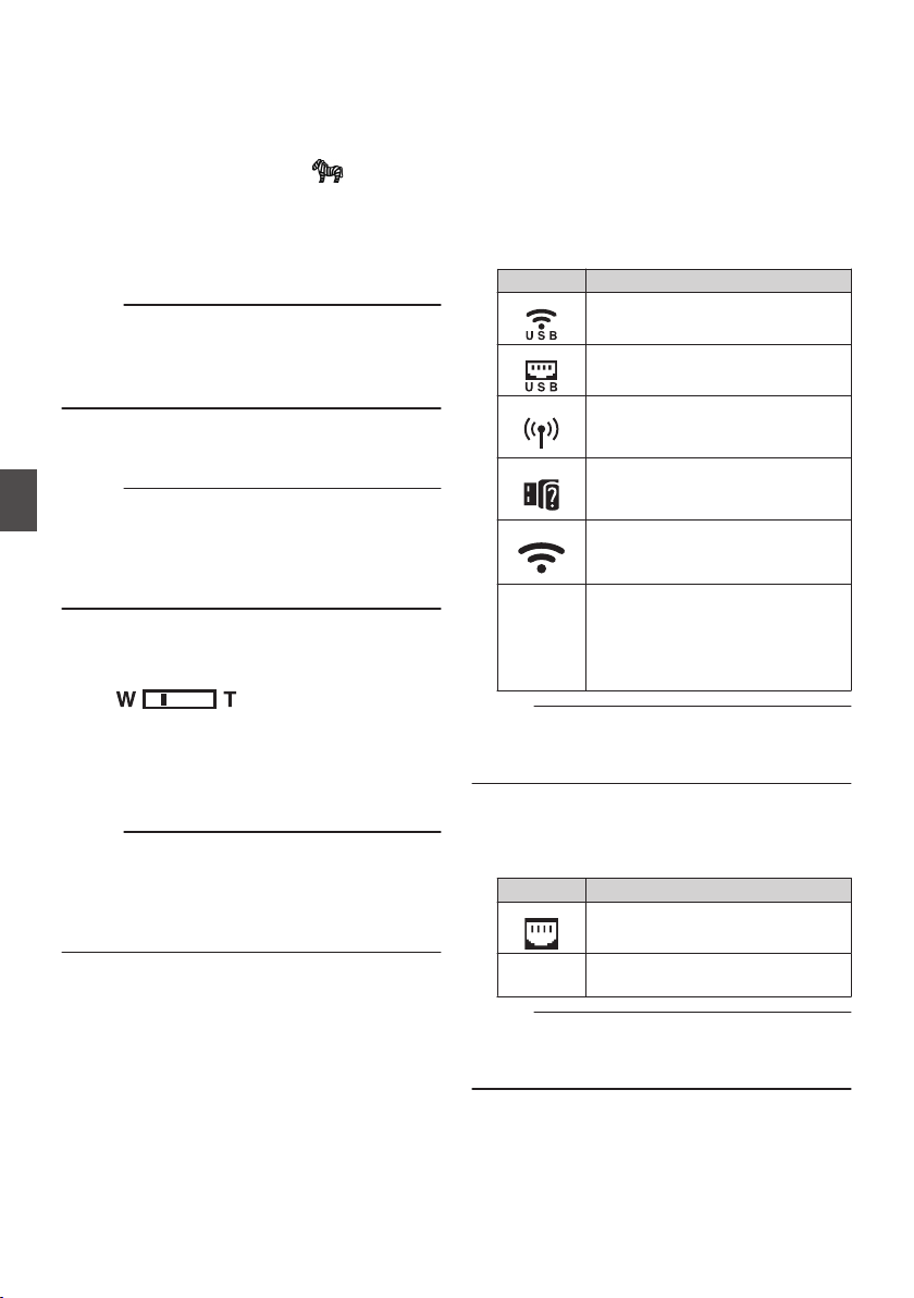
P
Luminance Information
Displayed when the Spot Meter function is
activated.
MAX : Maximum luminance
MIN : Minimum luminance
Q
Zebra pattern
During zebra pattern display,
(zebra icon)
is displayed on the display screen in Camera
mode.
(A P80 [Setting Zebra Pattern] )
R
Time Display
Displays the current time.
Memo :
0
The
date/time display style can be configured in
[System] B [Date/Time].
0
When [System] B [Record Set] B [Time
Stamp] is set to “On”, this item is not displayed.
S
Focus Display
Displays the approximate distance to the
subject in focus during manual focus.
Memo :
0
The displayed unit of measurement (feet or
meter) can be configured in [LCD/VF] B [Display
Type] B [Focus].
0
This item may not be displayed depending on
the lens used.
T
Zoom Display
0
Displays the zoom position. (Zoom bar or
value)
.
0
The zoom bar will only be displayed for 3
seconds after the zoom operation is
activated.
0
The value will always be displayed. (Z00 to
99)
Memo :
0
The mode of display (value or bar) can be
configured in [LCD/VF] B [Display Type] B
[Zoom].
0
This item may not be displayed depending on
the lens used.
U
Network Connection Icon
0
USB connection or built-in wireless LAN
connection u v
0
Set [Network] B [Connection Setup] B
[USB/Int. WLAN] to “On”. u v
(A
P140 [ USB/Int. WLAN u v ] )
0
In the case of connecting to an external
network, check the destination in
[Network]
B [Connection Setup] B
[Default Gateway].
(A P140
[ Default Gateway ] )
Icon Status
.
Wireless LAN connection from the
host terminal (USB) is established
.
Wired LAN connection from the
host terminal (USB) is established
.
Cellular adapter connection from
the host terminal (USB) is
established
.
When a USB adapter different
from the connection settings is
detected
.
Built-in wireless LAN connection is
established
u v
(No
display)
0
When [USB/Int. WLAN] is set
to “Off”
u v
0
When an unusable USB
adapter is detected
Memo :
0
The icon appears blinking when the camera
recorder is starting up, and is displayed in yellow
while getting ready to connect.
0
LAN terminal connection
In the case of connecting to an external network,
check the destination in [Network] B
[Connection Setup] B [Default Gateway].
Icon Status
.
LAN terminal connection is
established
(No
display)
When the LAN cable is not
connected
Memo :
0
The icon appears blinking when the camera
recorder is starting up, and is displayed in yellow
while getting ready to connect.
164
Display Screen in Camera Mode
Display/Status Screen
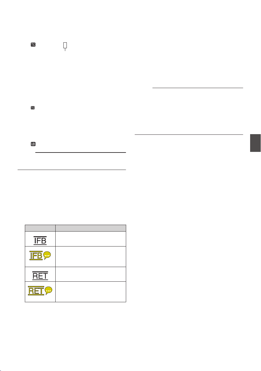
V
Time Code (I)/User’s Bit (J) Display
0
Displays the time code (hour: minute:
second: frame) or user’s bit data.
0
Example of time code display:
Display Screen
.
00:00:00:00
*
* Colon (:) denotes non-drop frames and dot
(.) denotes drop frames.
Enlarged Display
[NDF] is displayed to the right of [TC] in the
case of non-drop frames and [DF] in the case
of drop frames.
.
00H 00M 00S 00F
NDF
R-RUN
0
Example of user’s bit display:
Display Screen
.
FF EE DD 20
Memo :
0
Use the [TC DISPLAY] switch to toggle between
the time code display and user’s bit display.
W
Time Code Lock Indicator
When the built-in time code generator is
synchronized to the external time code data
input during the synchronization of time code
with another camera recorder, Z lights up.
When in the enlarged display mode, [EXTZ] is
shown in the TC mode display.
X
IFB/RET Mark
Displays the status of the IFB or Return over IP.
Icon Status
.
During audio feed only
.
(Yellow)
When an error occurs during
audio feed only
.
During video+audio feed
.
(Yellow)
When an error occurs during
video+audio feed
Y
SDI/HDMI Record Trigger
STBY B : When [SDI Rec Trigger] is set to
“Type-A” or “Type-B”, or [HDMI Rec
Trigger] is set to “On” and recording
is stopped
REC B : When [SDI Rec Trigger] is set to
“Type-A” or “Type-B”, or [HDMI Rec
Trigger] is set to “On” and recording
is in progress
Z
GPS Mark u v
When [System] B [GPS] is set to “On”, the
signal reception status is displayed.
Memo :
0
The display changes according to the signal
reception sensitivity. If signals cannot be
received, the H mark appears in yellow
regardless of the [LCD/VF] B [Display On/Off]
B [GPS] setting.
0
This item is not displayed when
[GPS] is set to
“Off”.
Display Screen in Camera Mode
165
Display/Status Screen
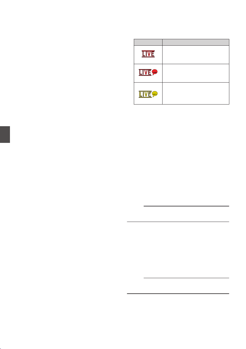
a
Media Status
---- : A card is not detected in the
selected slot, and [Tally
System] is also not set to
“Studio”
STBY : Recording standby
RREC : Recording
REVIEW : Clip Review
(A P84 [Viewing Recorded Videos Immediately
(Clip Review)] )
STBY P : Pre Rec recording standby
(A P90 [Pre Rec 0] )
RRECP : Pre Rec recording
(A P90 [Pre Rec 0] )
STBY C : Clip Continuous Rec recording
standby
(A P91 [Clip Continuous Rec 0] )
RRECC : Clip Continuous Rec recording
(A P91 [Clip Continuous Rec 0] )
STBYC
(displayed in
yellow)
: Clip Continuous Rec recording
pause
(A P91 [Clip Continuous Rec 0] )
STBY N : Interval Rec recording standby
(A P93 [Interval Rec 1] )
STBYN
(displayed in
red)
: Interval recording pause
RRECN : Interval Rec recording
(A P93 [Interval Rec 1] )
STBY M : Frame Rec recording standby
(A P92 [Frame Rec 1] )
RRECM : Frame Rec recording
(A P92 [Frame Rec 1] )
STBYM
(displayed in
yellow)
: Frame Rec recording pause
(A P92 [Frame Rec 1] )
STOP : Unable to record to the card in
the slot
P.OFF : Power OFF
Q
: During clip cutter recording
(displayed for 3 seconds)
(A P94 [Splitting the Clips Freely (Clip Cutter
Trig) 0] )
CALL : Receiving call signals from an
external device, such as a
remote control unit
PGM : Receiving program signals
from an external device, such
as a remote control unit
PVW : Receiving preview signals
from an external device, such
as a remote control unit
b
Live streaming mark
When [Network] B [
Live Streaming] B [Live
Streaming] is set to “On”, the distribution status
is displayed.
(A P141 [Live Streaming Item] )
Icon Status
.
(Red)
Distribution in progress (good
connection quality)
.
(Red)
Distribution in progress (poor
connection quality)
.
(Yellow)
Waiting for connection
(RTSP/RTP only), connection
failed
c
SDI Input Mode/High-Speed Frame Rate
0
“SDI INZ” is displayed when a device is
connected to the [HD/SD SDI IN] terminal,
and [System] B [Record Set] B [Record
Format] B [System] is set to “HD(SDI In)” or
“SD(SDI In)”2.
0
When [System] B [Record Set
] B [Record
Format] B [System] is configured to “High-
Speed”2, the setting value for [WFrame
Rate] is displayed.
d
OK Mark
Displayed
when OK mark has been appended.
(A P101 [Appending/Deleting OK Mark] )
e
Recording Format/Bit Rate (Enlarged Display
Mode Only)
Displays the recording format and bit rate (only
when in the enlarged display mode).
Memo :
0
The resolution, frame rate and bit rate can be
viewed on the status screen.
f
Event/Warning Display Area
Displays error messages.
(A P
218 [Error Messages and Actions] )
g
Dual Rec/ Backup Rec Display (Enlarged
Display Mode Only)
“DUAL” is displayed in the Dual Rec mode and
“BACKUP” is displayed in the Backup Rec
mode.
(A P155 [ Slot Mode ] )
Memo :
0
Displayed only when in the enlarged display
mode.
166
Display Screen in Camera Mode
Display/Status Screen
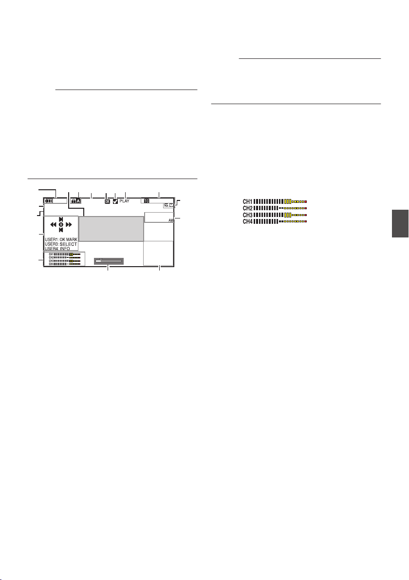
Display Screen in Media
Mode
When the display setting for [LCD/VF] B [Display
On/Off] is set to “Off”, the corresponding display is
hidden.
Memo :
0
Display on the information display area can be
toggled using the [USER4] button.
0
When the display screen is turned off, it will
appear only in the following cases.
0
During event display or warning display
0
If “VF Display” is assigned to the [USER1(VF)]
button or [USER2(VF)] button of the viewfinder,
the corresponding button can also be used in the
Media mode.
.
Jan 24 ,2018
1920x1080
30p 50M
282min
12 :34 : 56
00: 00: 00.00
1000/2000
A
JK
N
O
L
M
E
G
H
I
B
D
C
F
P
A
Voltage/Battery Power
Displays the current status of the power supply
in use.
(A P36 [Power Status Display] )
Memo :
0
Even when the display screen is turned off and
[LCD/VF] B [Display On/Off] B [Battery] is set to
“Off”, this will be displayed when there is a
warning.
B
Resolution
Displays the video image resolution.
C
Frame Rate/Bit Rate
Displays the frame rate and bit rate in pairs.
D
Operation Guide
Displays a guide for the current operation
buttons.
E
Audio Level Meter
0
Displays the audio levels for CH-1 to CH-4.
.
F
Position Bar
Displays the current position in the video.
During trimming, the position bar appears in
green, and icons for the in and out points are
displayed.
6
: Current position of the video
7
: Position to start trimming
(In point)
8
: Position to end trimming
(Out point)
Display Screen in Media Mode
167
Display/Status Screen
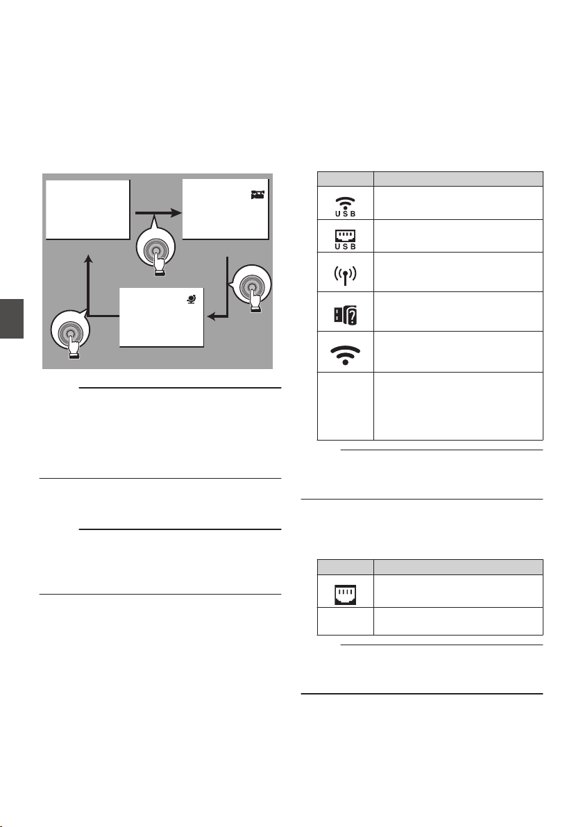
G
Information Display
Use the [USER4] button to switch between
camera information display, GPS display and
turning off the display.
0
The
GPS display displays information on the
recording location of the video being played
back only when GPS information has been
recorded.
0
Camera information display displays only
information of Gain, Iris, Shutter and White
Balance that have been recorded.
.
5600K
1/100
F1. 6
0
dB
+35.483197
+139.652172
USER4
USER4
USER4
GPS Display
Camera Information Display
Display Off
Memo :
0
Trimming information is displayed while
trimming is in progress. In this case, pressing the
[USER4] button does not switch the display.
0
The information display area is not subject to the
display settings of the items in [LCD/VF] B
[Display On/Off].
H
Date/Time Display
Displays the date/time that is recorded on the
currently played recording media.
Memo :
0
The date/time display style can be specified in
[System] B [Date Style]/[Time Style].
(A P150 [ Date Style ] )
(A P150 [ Time Style ] )
I
Network Connection Icon
0
USB connection or built-in wireless LAN
connection u v
0
Set [Network] B [Connection Setup] B
[USB/Int. WLAN] to “On”. u v
(A P140
[ USB/Int. WLAN u v ] )
0
In the case of connecting to an external
network, check the destination in
[Network] B [Connection Setup] B
[Default Gateway].
(A P140
[ Default Gateway ] )
Icon Status
.
Wireless LAN connection from the
host terminal (USB) is established
.
Wired LAN connection from the
host terminal (USB) is established
.
Cellular adapter connection from
the host terminal (USB) is
established
.
When a USB adapter different
from the connection settings is
detected
.
Built-in wireless LAN connection is
established
u v
(No
display)
0
When [USB/Int. WLAN] is set
to “Off”
u v
0
When an unusable USB
adapter is detected
Memo :
0
The icon appears blinking when the camera
recorder is starting up, and is displayed in yellow
while getting ready to connect.
0
LAN terminal connection
In the case of connecting to an external network,
check the destination in [Network] B
[Connection Setup] B [Default Gateway].
Icon Status
.
LAN terminal connection is
established
(No
display)
When the LAN cable is not
connected
Memo :
0
The icon appears blinking when the camera
recorder is starting up, and is displayed in yellow
while getting ready to connect.
168
Display Screen in Media Mode
Display/Status Screen

J
Time Code (I)/User’s Bit (J) Display
0
Displays the time code (hour: minute:
second: frame) or user’s bit data recorded in
the recording media being played back.
0
Example of time code display:
.
00:00:00:00
*
* Colon (:) denotes non-drop frames and dot
(.) denotes drop frames.
0
Example of user’s bit display:
.
FF EE DD 20
Memo :
0
Use the [TC DISPLAY] switch to toggle between
the time code display and user’s bit display.
K
Media Status
PLAY : Playing
STILL : Still picture playback mode
FWD * : High-speed playback in the
forward direction (* playback
speed: 5x, 15x, 60x, or 360x)
REV * : High-speed playback in the
reverse direction (* reverse
playback speed: 5x, 15x, 60x, or
360x)
STOP : Stop mode
P.OFF : Power OFF
L
Check Mark
Displayed when the currently played clip is
selected.
M
OK Mark
Displayed when OK mark has been appended.
(A P101 [Appending/Deleting OK Mark] )
N
Clip Information
Displays current clip number/total number of
clips.
O
Media
0
Displays the media slot (W or Y) of the
currently played clip.
0
z
appears when the write-protect switch of
the SD card is set.
P
Event/Warning Display Area
Displays error messages.
(
A P218 [Error Messages and Actions] )
Display Screen in Media Mode
169
Display/Status Screen
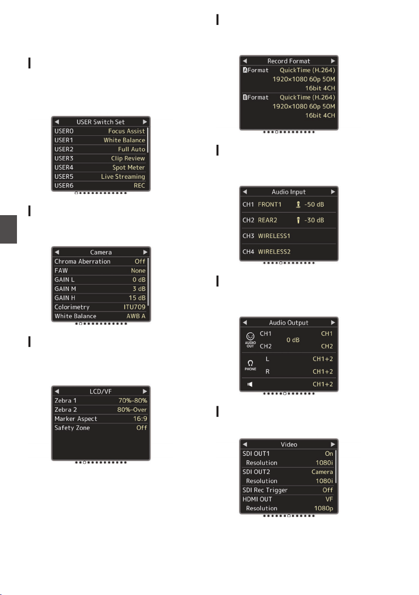
Status Screen
For checking the settings of the camera recorder.
USER Switch Set Screen
For checking the status (functions assigned) of the
user buttons.
(A P45 [Assignment of Functions to User
Buttons] )
.
Camera Screen
For checking information related to shooting using
the camera recorder.
.
LCD/VF Screen
For checking information related to the contents
displayed on the LCD monitor and viewfinder
screens.
.
Record Format Screen
For checking settings related to the recording
format.
.
Audio Input Screen
For checking settings related to audio input
channels and their input levels.
.
Audio Output Screen
For checking settings related to audio output
channels and their output levels.
.
Video Screen
For checking the settings related to video output.
.
170
Status Screen
Display/Status Screen
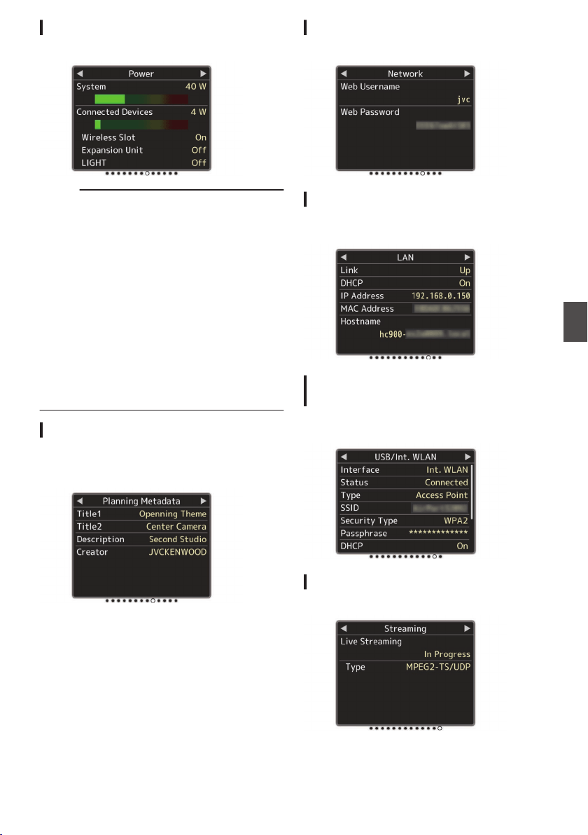
Power Screen
For checking the power consumption.
.
Memo :
0
[System] shows the power consumption of the
entire camera system (camera recorder +
connecting devices) while [Connected
Devices] shows the estimated power
consumption of the peripheral equipments such
as lens and wireless slots.
0
When the bar on the bar graph enters the red
zone, it indicates that the power consumption
has exceeded its rating. As this may result in
malfunction, do keep the power consumption
within the rating.
0
If
[System] shows a value that exceeds the
rating, the power to the [LIGHT], [DC OUT] (rear)
and [DC OUT] (LAN) terminals is automatically
cut off. This is not a malfunction. Use peripheral
equipments with lower power consumption then
turn on the power of this camera recorder again.
Planning Metadata Screen
For checking the current planning metadata
setting.
(A P195 [ Planning Metadata ] )
.
Network Screen
For checking the network login information.
.
LAN Screen
For checking the network information for LAN
connection.
.
USB/Int. WLAN Screen v v
USB Screen
w x
For checking the network information for the USB
adapter and built-in wireless LAN connections.
.
Streaming Screen
For viewing information related to live streaming.
.
Status Screen
171
Display/Status Screen
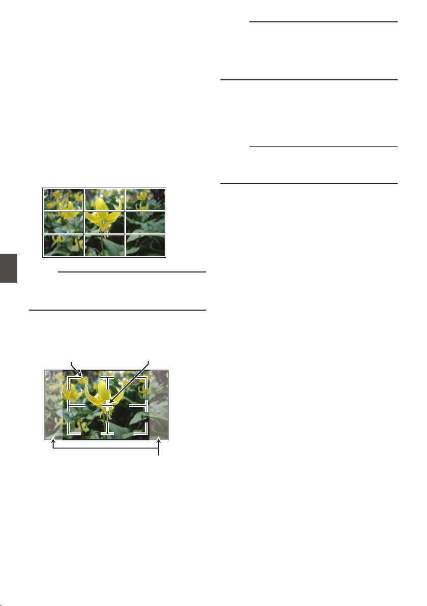
Marker and Safety Zone
Displays (Camera Mode
Only)
The marker and safety zone displays are useful in
helping you determine the angle of view for the
image according to the shooting purpose.
The marker is displayed only in the Camera mode.
Displaying the Grid Marker
1
Set [LCD/VF]
B [Marker Settings
]
B [Grid
Marker] to “On”.
(A P
128 [ Grid Marker ] )
A grid that divides the screen into 3x3 is
displayed.
.
Memo :
0
When [Grid Marker] is set to “On”, [Aspect
Ratio], [Aspect Marker], and [Safety Zone] do
not function.
0
Example of display when [Aspect Ratio] = “4:3”,
[Aspect Marker] = “Line+Halftone”, and [Center
Mark] = “On”
.
Aspect Marker
Center MarkSafety Zone
Memo :
0
You can turn On/Off the safety zone and center
mark displays using [LCD/VF] B [Marker
Settings] B [Aspect Ratio], [Safety Zone], and
[Center Mark].
(A P
128 [ Safety Zone ] )
Color Bar Output
Color bars can be output on this camera recorder.
Memo :
0
The audio test signals (1 kHz) can be output
simultaneously with the color bar output.
(A P137
[ Test Tone ] )
To output color bars, follow the setting procedure
below.
1
Set the [OUTPUT] switch to “BARS”.
Color bars are output.
172
Marker and Safety Zone Displays (Camera Mode Only)
Camera Features

Adjusting the Gamma
The gamma curve can be adjusted to various
characteristics when Color Space is set to a value
other than “HLG” and “J-Log1”.
(A P116 [ Color Space ] )
(A P116 [ Gamma ] )
Standard : Standard gamma curve based on
video standard.
The adjustable level is 0.35 to 0.45
to 0.55 in steps of 0.01.
When the level is at 0.45, the
gamma curve becomes one that
conforms to the ITU709 standard.
Cinema 1 : Sets to a cinema-like gamma
curve.
The level can be adjusted
extensively from -10 to 0 to +10.
Cinema 2 : Sets to a gamma curve with soft
expression giving priority to high
luminance gradation.
The level can be adjusted
extensively from -10 to 0 to +10.
Gamma Variation
The typical characteristics are shown in the
following figure. The figure shows the
characteristics when “Standard”, “Cinema 1” or
“Cinema 2” is configured and [Knee Level] is set to
“95%” for the “Standard” or “Cinema 1” graph.
.
STANDARD 0.45
Cinema2 NORMAL
Cinema2 -5
Cinema2 -10
Cinema2 +10
Cinema1 NORMAL
Cinema1 -10
Cinema1 +10
Cinema1
+10
Cinema1
0
Cinema1
-10
Cinema2
+10
Cinema2
-5
Cinema2
0
Cinema2
-10
STANDARD
0.45
0
20
40
60
80
100
120
0 100 200 300 400 500 600
SCEAN(%)
OUTPUT (IRE)
HLG and J-Log1 Gamma
The gamma switches automatically to the
respective “HLG Gamma” and “J-Log1 Gamma”
when [Color Space] is set to “HLG” or “J-Log1”.
The HLG Gamma becomes an ITU2100 HLG HDR
gamma. Output signals above 100 IRE can be
clipped by adjusting “White Clip”.
The J-Log1 Gamma becomes a Log gamma with
dynamic range of max 800%.
.
INPUT (%)
HLG
J-Log1
ITU709+KNEE
J-Log1
HLG
STANDARD0.45
+KNEE 95%
OUTPUT (IRE)
0
20
40
60
80
100
120
0 100 200 300 400 500 600 700 800
Adjusting the Gamma
173
Camera Features
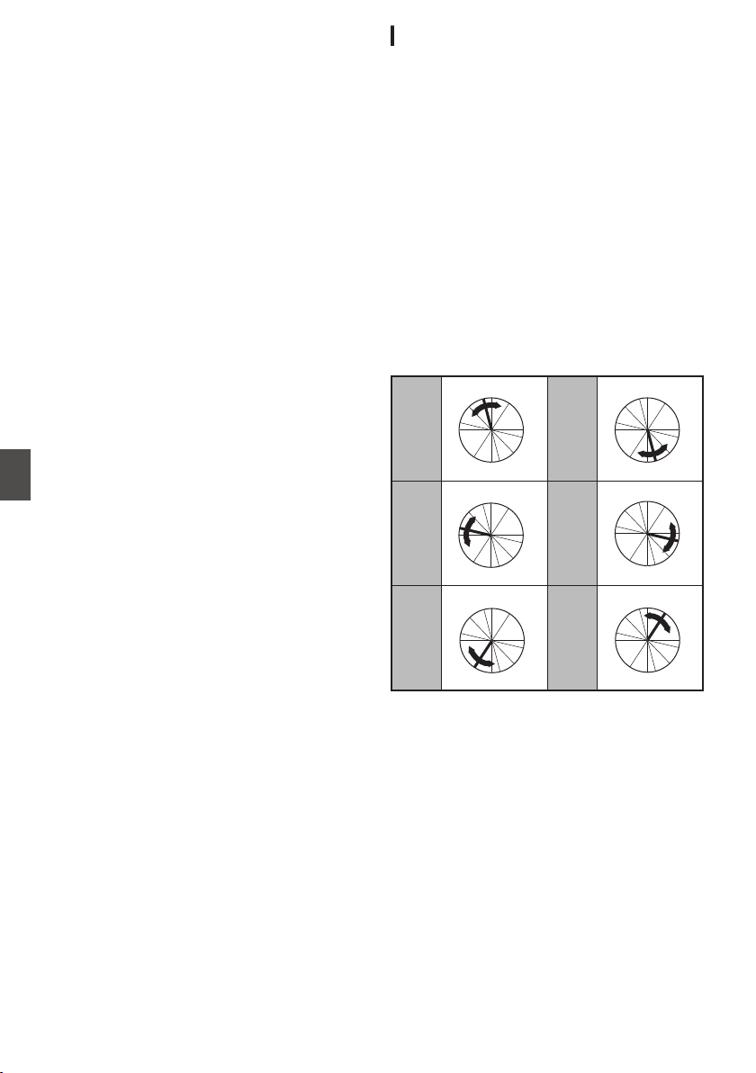
Adjusting Color Matrix
0
The color matrix of the camera recorder can be
adjusted to a color of the user’s preference.
0
When shooting is performed using multiple
cameras,
the colors of the different cameras can
be adjusted, and a color of the user’s preference
can be set on this camera recorder.
0
Adjust the color on the vector scope and
waveform monitor using the DSC color chart.
* The adjusted values of “Natural”, “Standard”,
“Cinema Vivid”, and “Cinema Subdued” in
[Color Matrix] can be stored individually.
(A P119 [ Color Matrix ] )
Linear Matrix Adjustment
The Saturation, Hue and Lightness of the primary
and complementary colors (6 colors in total) can be
set individually.
1
Set [Camera Process]
B [
Color Matrix]/
[Adjust]
B [Linear Adjust] to “On” and
select [Adjust].
(A P119
[ Color Matrix ] )
2
Adjust Hue.
0
Select the color using the cross-shaped
button (JK) and confirm using the cross-
shaped button (I). (The cursor moves to
Hue.)
0
Pressing the cross-shaped button (J)
rotates the hue in the clockwise direction on
the vector scope.
0
Pressing the cross-shaped button (K)
rotates the hue in the anti-clockwise direction
on the vector scope.
.
R
Cy
B
G
Y
I
Mg
R
Cy
B
G
Y
I
Mg
R
Cy
B
G
Y
I
Mg
R
Cy
B
G
Y
I
Mg
R
Cy
B
G
Y
I
Mg
R
Cy
B
G
Y
I
Mg
Magenta
Green
BlueYe l l o w
CyanRed
174
Adjusting Color Matrix
Camera Features
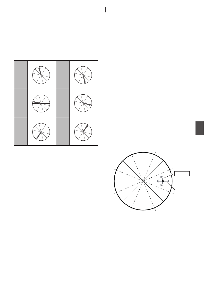
3
Adjust Saturation.
0
Press the cross-shaped button (I) to move
the cursor to Saturation.
0
Each of the colors changes in the direction
indicated by the arrow on the vector scope.
0
Pressing the cross-shaped button (J) moves
the color outward from the center of the circle
on the vector scope.
0
Pressing the cross-shaped button (K) moves
the color toward to the center of the circle on
the vector scope.
.
R
Cy
B
G
Y
I
Mg
R
Cy
B
G
Y
I
Mg
R
Cy
B
G
Y
I
Mg
R
Cy
B
G
Y
I
Mg
R
Cy
B
G
Y
I
Mg
R
Cy
B
G
YI
I
Mg
Magenta
Green
BlueYe l l o w
CyanRed
4
Adjust Lightness.
0
Pressing the cross-shaped button (J)
lightens; and pressing the cross-shaped
button (K) darkens.
0
Press the cross-shaped button (I) to return
the cursor to Hue.
Multi-Matrix Adjustment
Multi-matrix adjustment is capable of advanced
configuration of the Saturation and Hue for 16
colors than linear adjustment.
1
Set [Camera Process]
B [Color Matrix
]/
[Adjust]
B [Multi Adjust] to “On” and select
[Adjust].
(A P
119 [ Color Matrix ] )
2
Adjust Hue.
0
Select the color using the cross-shaped
button (J K) and confirm using the cross-
shaped button (I). (The cursor moves to
Hue.)
0
Pressing the cross-shaped button (J)
rotates the hue in the clockwise direction on
the vector scope.
0
Pressing the cross-shaped button (K)
rotates
the
hue in the anti-clockwise direction
on the vector scope.
3
Adjust Saturation.
0
Press the cross-shaped button (I) to move
the cursor to Saturation.
0
Pressing the cross-shaped button (J) moves
the color outward from the center of the circle
on the vector scope.
0
Pressing the cross-shaped button (K) moves
the color toward to the center of the circle on
the vector scope.
.
Yl+
R-
R
R+
Mg-
Mg
B-
B+
B
CY-
CY
Cy+
G-
G+
Yl
G
Hue
Saturation
Adjusting Color Matrix
175
Camera Features
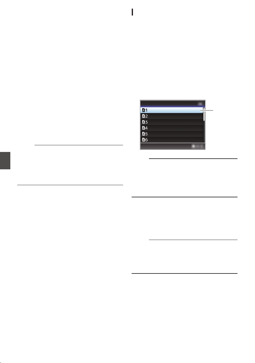
Configuring Setup Files
The menu settings can be stored on an SD card by
saving them as a setup file.
Loading a saved setup file enables you to
reproduce the appropriate setup state speedily.
The following types of setup files are available.
o
Picture File:
File that contains image creation settings in
accordance to the shooting conditions ([Camera
Process] menu items).
o
All File:
File that contains all menu settings, ranging from
video
format settings to image creation settings
such as device settings and shooting
conditions, as well as the contents of the
[Favorites Menu]. Settings in Network Settings
are not saved.
o
User File:
File that contains settings from All File that are
not included in the [Camera Process] menu
items.
(A P116 [Camera Process Menu] )
Memo :
0
Make use of the [Setup File] menu to save or
load a setup file.
0
The following operations can be performed on
the [Setup File] menu.
0
[Saving Setup Files] (A P 176
)
0
[Loading a Setup File] (A P 177)
Number of Storable Setup Files
SD slot A : [ W 1 ] to [ W 8 ]
SD slot B : [ Y 1 ] to [ Y 8 ]
Compatibility
o
User File/All File
0
Only
User
File/All File of the GY-HC900 series
can be loaded.
o
Picture File
Only Picture File of the GY-HC900 series can be
loaded.
Saving Setup Files
1
Display the [Setup File] menu.
Select [System] B [Setup File
] and press the
Set button (R).
(A P148 [ Setup File ] )
2
Select [Store File] and press the Set button
(
R).
3
Select [Picture File], [User File] or [All File],
and press the Set button (
R).
The existing files are displayed.
4
Select the file to be newly saved (or
overwritten) using the cross-shaped
button (
JK), and press the Set button (R).
.
4
<no file>
<no file>
<no file>
<no file>
<no file>
<no file>
Store Picture File
Memo :
0
Files cannot be written in the following cases.
(Displayed in gray, selection disabled)
0
When the inserted SD card is not supported or
not formatted. (File name appears as “---”.)
0
When a write-protected SD card is inserted
(a z mark appears beside the SD card icon).
5
Name the file.
0
Enter the subname using the software
keyboard.
(A P107 [Text Input with Software Keyboard] )
0
You can enter up to 8 characters for the
[Store File]/[Picture File] subname.
Memo :
0
When overwriting an existing file, the subname
of the existing file is displayed.
0
Select [Cancel] and press the Set button (R), or
press the [CANCEL/RESET] button to return to
the previous screen.
176
Configuring Setup Files
Camera Features
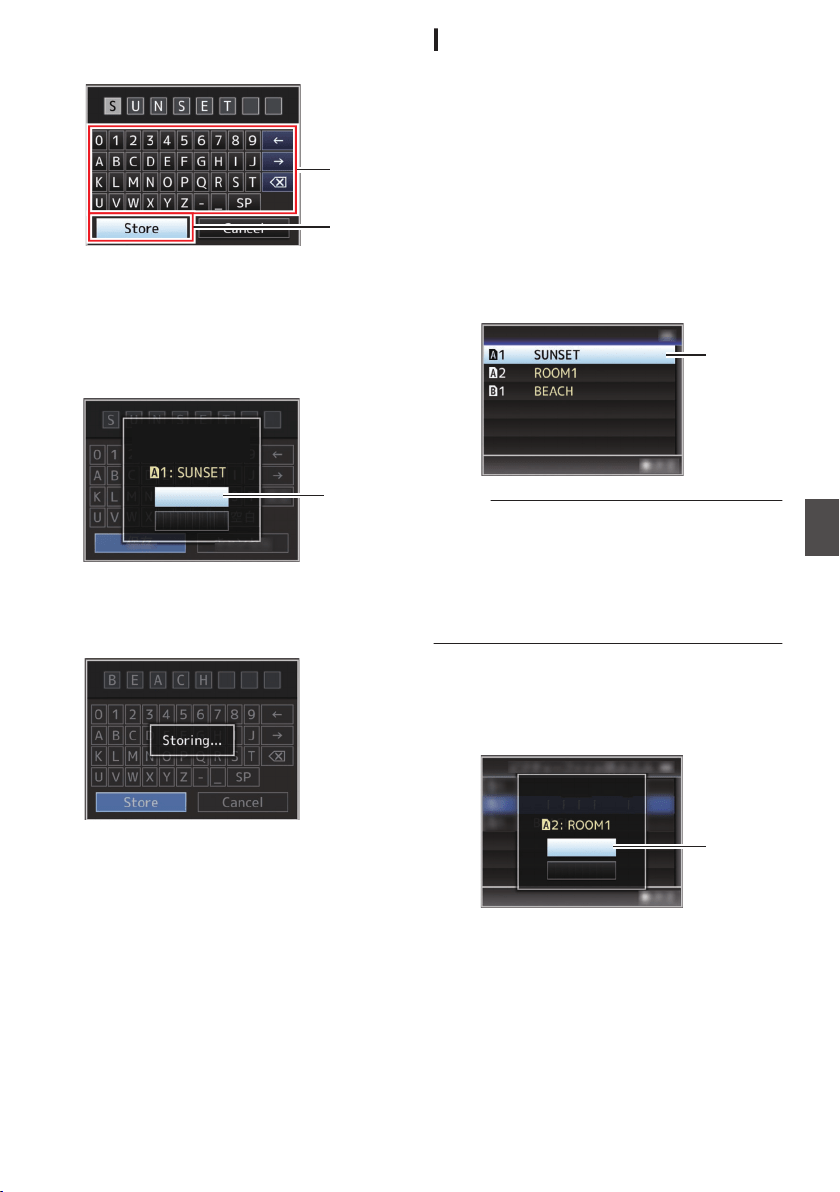
6
Select [Store] and press the Set button (
R).
.
6
5
7
Save the file.
0
A confirmation screen appears when you
choose to overwrite.
Select [Overwrite] on the confirmation
screen, and press the Set button (R). Saving
starts, and “Storing...” appears on the screen.
.
:SUNSET
7
Load Picture File
Cancel
Overwrite
Overwrite Picture File?
0
Saving starts, and “Storing...” appears on the
screen when the file is newly saved.
.
8
Saving is complete.
After saving of the file is complete, “Complete”
appears on the screen, and the menu screen
closes automatically.
Loading a Setup File
1
Display the [Setup File] menu.
Select [System] B [Setup File
] and press the
Set button (R).
(A P148 [ Setup File ] )
2
Select [Load File] and press the Set button
(
R).
3
Select [Picture File], [User File] or [All File],
and press the Set button (
R).
The existing files are displayed.
4
Select the file to load using the cross-
shaped button (
JK), and press the Set
button (
R).
.
4
Load Picture File
Memo :
0
When the write-protect switch of the inserted SD
card is set, a z mark appears beside the SD
card icon. Setup files can be loaded from an SD
card even if the write-protect switch is set.
0
Setup files that are completely incompatible will
not be displayed.
(A P176 [Configuring Setup Files] )
5
Select [Load] on the confirmation screen,
and press the Set button (
R).
Loading starts, and “Loading...” appears on the
screen.
.
5
Cancel
Load
Load Picture File?
6
Reading is complete.
After reading of the file is complete, “Complete
”
appears on the screen, and the menu screen
closes automatically.
Configuring Setup Files
177
Camera Features
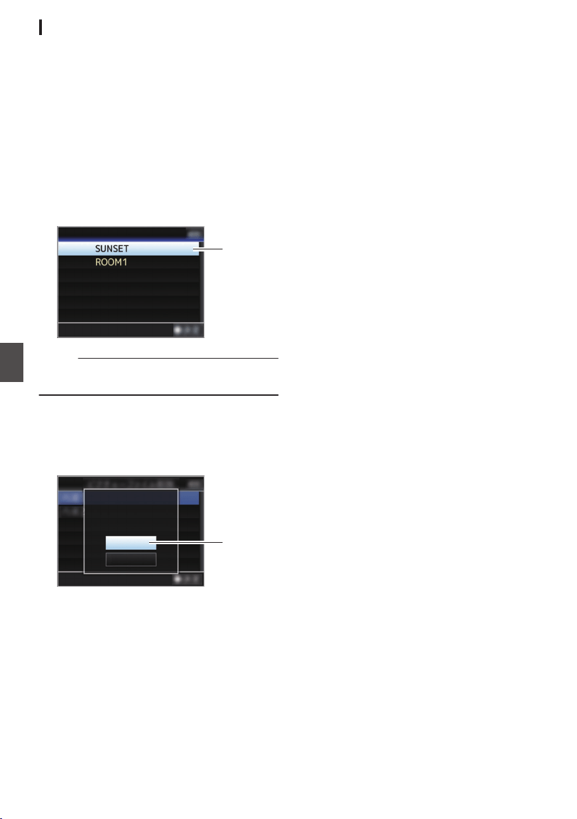
Deleting Setup Files
1
Display the [Setup File] menu.
Select [Main Menu] B [System] B [Setup File]
and press the Set button (R).
(A
P148 [ Setup File ] )
2
Select [Delete File] and press the Set button
(
R).
3
Select [Picture File], [User File] or [All File],
and press the Set button (
R).
The existing files are displayed.
4
Select the file to delete using the cross-
shaped button (
JK), and press the Set
button (
R).
.
4
CAM2
CAM1
Delete Picture File
Memo :
0
Setup File saved on the SD card cannot be
deleted.
5
Select [Delete] on the confirmation screen,
and press the Set button (
R).
Deletion starts, and “Deleting...” appears on the
screen.
.
:SUNSET
5
Cancel
Delete
CAM1
Delete Picture File?
6
Deletion is complete.
After file deletion is complete, “Complete”
appears on the screen.
178
Configuring Setup Files
Camera Features
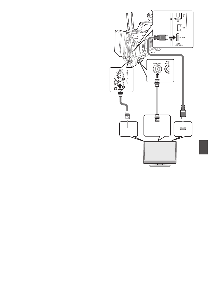
Connecting External
Monitor
0
To output live or playback video images and
audio sound to an external monitor, select the
output signals from the camera recorder, and
connect
using an appropriate cable according to
the monitor to be used.
0
Choose the most suitable terminal according to
the monitor in use.
0
[HD/SD SDI OUT] terminal:
Outputs either the 3G-SDI/HD-SDI signal or SD-
SDI signal.
0
[VIDEO OUT] terminal:
Outputs composite video signals.
0
[HDMI] terminal:
Outputs HDMI signals.
Memo :
0
If the [HD/SD SDI OUT] terminal or [HDMI]
terminal is connected, configure the settings in
the [A/V Set] menu according to the monitor to
be connected.
(A P131
[ SDI OUT1 ] )
(A P132 [ SDI OUT2 ] )
(A P132 [ HDMI OUT ] )
(A P132 [ VIDEO OUT ] )
.
SDI IN
HDMI
VIDEO IN
* Select the output signal in [A/V Set] B [SDI
OUT1]/[SDI OUT2]/[HDMI OUT].
(A P
131 [ SDI OUT1 ] )
(A P132 [ SDI OUT2 ] )
(A P132 [ HDMI OUT ] )
* When [Record Format] B [System] is set to
“SD”2, only SD-SDI signals are output.
(A P151 [ System ] )
* To display the menu screen or display screen on
the external monitor, set [A/V Set] B [Video
Set] B[SDI OUT2 Char.]/[HDMI Char.]/[Video
OUT Char.] to “On”.
(A P131 [ SDI OUT2 Char. ] )
(A P131 [ HDMI Char. ] )
(A P131 [ Video OUT Char. ] )
Connecting External Monitor
179
Connecting External Devices
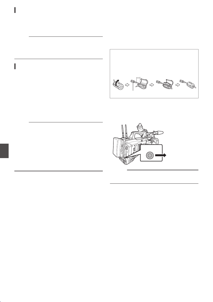
Connecting via SDI
0
Digital video signals, together with embedded
(superimposed) audio signals and time code
signals, are output for both the 3G-SDI/HD-SDI
and SD-SDI signals.
Memo :
0
The sampling frequency for embedded
(superimposed) audio signals is 48 kHz. Time
code of the built-in time generator as well as
playback time code are also output.
Setting the Aspect
0
For setting the mode to convert images with a
16:9 aspect ratio to display on a 4:3 aspect ratio
screen.
0
Set using [A/V Set] B [Video Set] B [SD
Aspect].
0
The
available modes include “Side Cut”, “Letter”
(blackened at the top and bottom), and
“Squeeze” (full size, compressed at the left and
right).
(A P134
[ SD Aspect ] )
Memo :
0
When [Record Format]
B
[System] is set to “SD”,
and [SD Aspect] is set to “4:3”, this item cannot be
selected.
0
When [Record Format] B [System] is set to
“SD”2, and [SD Aspect] is set to “16:9”,
“Side Cut” in [A/V Set] B [Video Set] B [SD
Aspect] cannot be selected.
(A P151
[ System ] )
(A P154 [ SD Aspect 2 ] )
Connecting a Remote
Control Unit
The switch functions of the camera recorder can be
configured using the remote control unit.
* Remote control units supported: RM-LP25U,
RM-LP55U, RM-LP20G
o
Attaching Core Filter Beforehand v
Before using the remote control unit, attach the
core filter (small) to the remote cable of the
remote control unit.
.
Release the
stopper.
5 cm
Wind twice
To be connected to the camera recorder. [Core filter (small)]
1
Connect the remote control unit to the
camera recorder.
Connect the remote cable of the remote control
unit to the
[REMOTE] terminal.
.
REMOTE
Connect to the
Remote Control
Unit
Caution :
0
Turn off the power of the camera recorder when
connecting a remote control unit.
2
Turn on the power of the camera recorder.
3
Set the operate switch of the remote control
unit to ON.
Precautions on Using the Remote Control Unit
0
When the switches of the camera recorder and
remote control unit are operated at the same
time, the switch operation of the remote control
unit takes priority over that of the camera
recorder.
0
Focus and zoom operations cannot be
performed using the remote control unit.
0
The shutter speed may vary slightly from the
value displayed on the camera recorder.
0
While
the camera recorder is in the Media mode,
the Auto White Balance feature does not
function even if you operate it from the remote
control unit.
180
Connecting External Monitor
Connecting External Devices
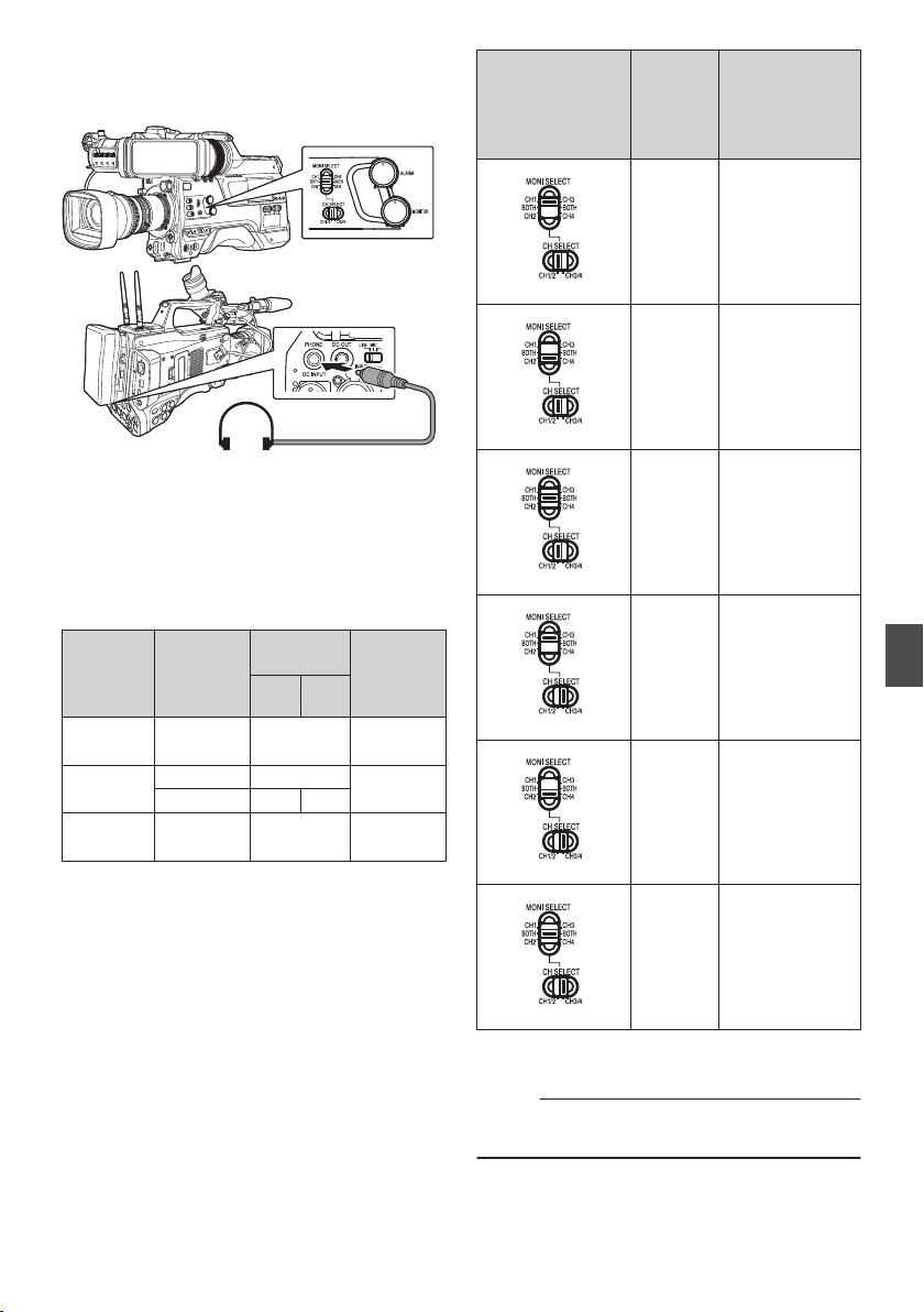
Connecting the
Headphone
.
0
Audio output from the [PHONE] terminal can be
selected using [A/V Set] B [Audio Set] B
[PHONE Output] and the combination of the
[MONI SELECT] and [CH SELECT] switches.
(A
P137 [ PHONE Output ] )
0
The outputs from the [PHONE] terminal and
monitor speaker are as follows according to the
different combinations of settings.
[MONI
SELECT
]
Switch
Setting
[PHONE
Output
]
Setting
[PHONE]
Terminal
Speaker
L R
[CH1/
CH3]
- CH1 CH1
[BOTH]
Mix CH1+CH2
CH1+CH2
Stereo CH1 CH2
[CH2/
CH4]
- CH2 CH2
1
Connect the headphone.
2
Select the channels to monitor using the
different combinations of the [MONI
SELECT
] and [MONI SELECT] switches.
Combinations of
[MONI SELECT]
and [CH
SELECT]
Switches
Channels
to
Monitor
Description
.
CH1 The audio input to
[CH1] is output.
.
CH2 The audio input to
[
CH2] is output.
.
CH1/CH2 The audio inputs
to [CH1] and
[CH2] are output.
.
CH3 The audio input to
[CH3] is output.
.
CH4 The audio input to
[CH4] is output.
.
CH3/CH4 The audio inputs
to [CH3] and
[CH4] are output.
3
Use the [MONITOR] adjustment knob to
adjust the monitor volume.
Memo :
0
There is no sound output from the speaker when
the headphone is connected.
Connecting the Headphone
181
Connecting External Devices
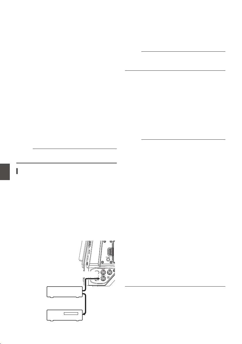
Inputting External
Synchronizing Signals
(Genlock)
0
A [GENLOCK]
terminal is available on the side
of the camera recorder.
0
You can input synchronizing signals from
FS-790 (sold separately) or FS-900 (sold
separately) that is connected to the accessory
connection terminal (68 pins) on the rear of the
camera recorder.
0
SDI signals (digital signals) can be input from the
[HD/SD SDI IN] terminal.
0
Input external synchronizing signals from the
[GENLOCK] terminal and [HD/SD SDI IN]
terminal, and synchronize the camera video with
the external signal.
0
Input external synchronizing signals from the
[GENLOCK] terminal, and synchronize the
camera video with the external signal.
0
The H (Horizontal) Phase of the camera
recorder’s video signals can be adjusted with
respect to
the external synchronizing signals on
the [A/V Set] B [Video Set] B [Genlock Adjust]
screen.
(A P134 [ Genlock Adjust... ] )
Memo :
0
The genlock feature is only usable in the Camera
mode.
Genlock Signal Settings
For analog signal input
o Synchronizing signal used
SD synchronizing
signal
:
BB (Black Burst) signal
Supports SMPTE170M
(RS-170A)-NTSC
Supports ITU-R BT.470-6 PAL
HD synchronizing
signal
:
HDTV tri-level synchronizing
signal
Supports SMPTE ST296-
HD720p
Supports SMPTE ST274-
HD1080i
.
GENLOCK
Video
Equipment
External Synchronizing Signal
External Synchronizing Signal
SYNC Signal
Generator
1
Set the camera recorder to the Camera
mode.
(A P20 [Operation Modes] )
2
Set [Genlock Input] to “GENLOCK”.
Set [A/V Set] B [Video Set] B [Genlock Input] to
“GENLOCK”.
(A P134 [ Genlock Input ] )
Memo :
0
Set to “Adapter” to input synchronizing signal
from the accessory connection terminal (68
pins) on the rear of this unit.
3
When in the standby or stop mode, input
synchronizing signals from the SYNC
signal generator to the [GENLOCK]
terminal.
0
When the camera recorder’s video is locking
to the external synchronizing signal, “Sync
Locking” appears on the screen.
0
After locking to the external synchronizing
signal is complete, the display disappears
and recording can be performed.
0
If there is genlock signal input but the signal
format is not supported, “Invalid Sync” is
displayed.
Memo :
0
If the frame rate in [WFrame & Bit Rate]/
[YFrame & Bit Rate] in the [Record Format]
menu is set to “60p”, “60i” or “30p”, 59.94 Hz
synchronizing signals (vertical synchronization)
are input.
50 Hz/60 Hz synchronizing signals are not
synchronized.
0
If the frame rate of [WFrame & Bit Rate]/
[YFrame & Bit Rate] in the
[Record Format]
menu is set to “50p”, “50i”, or “25p”, 50 Hz
synchronizing signals (vertical synchronization)
are input.
59.94 Hz/60 Hz synchronizing signals are not
synchronized.
(A P
152 [ W Frame Rate ] )
0
Do not connect or disconnect the input cable for
the synchronizing signals during recording or
playback
0
If the power is turned on during input of external
synchronizing signals, vertical oscillation may
occur. This is not a malfunction.
0
Signals such as VTR playback signals with
jitters may not be synchronized on this camera
recorder.
0
Only H (Horizontal) and V (Vertical) genlock
functions are available on this camera recorder.
It does not come with a lock function for SC (sub-
carrier). Color flash may occur during switching
such as when composite signals are used by a
switcher.
182
Inputting External Synchronizing Signals (Genlock)
Connecting External Devices
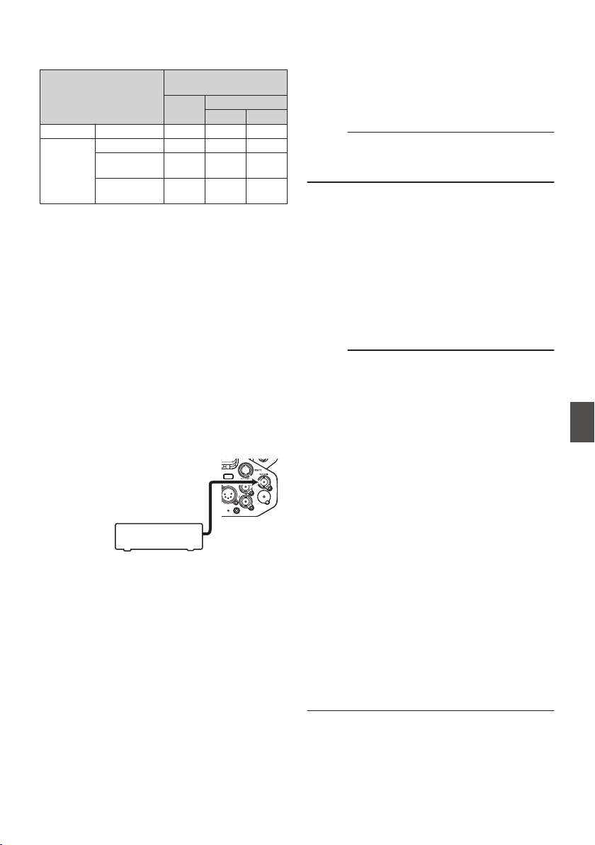
o Phase Items to Synchronize
The phase items to be synchronized may vary
depending on the input synchronizing signal and
output video signal.
Output Video Signal
Input Synchronizing
Signal
BB Tri-sync
720p 1080i
VIDEO Composite H, V, F V V, F
SDI
SD-SDI H, V, F V V, F
HD-SDI
720p
V H, V V
HD-SDI
1080i
V, F V H, V, F
H
:
Horizontal Phase
V
:
Vertical Phase
F
:
Field Phase
For digital signals (SDI) input
Input external synchronizing signals from the
[HD/SD SDI IN] terminal, and synchronize the
camera video or playback image with the external
signal.
Input external synchronizing signals from the
[HD/SD SDI IN] terminal, and synchronize the
camera video with the external signal.
o Synchronizing signal used
SD synchronizing
signal
:
Supports SMPTE259M
HD synchronizing
signal
:
Supports SMPTE ST296
3G-SDI
synchronizing
signal
:
Supports SMPTE ST424
.
+'6'6',,1
External Synchronizing Signal
SYNC Signal
Generator
1
Set the camera recorder to the Camera
mode.
(A P20 [Operation Modes] )
2
Set [Genlock Input] to “SDI IN”.
Set [A/V Set] B [Video Set] B [Genlock Input] to
“SDI IN”.
(A P134 [ Genlock Input ] )
Memo :
0
Set to “Adapter” to input synchronizing signal
from the accessory connection terminal (68
pins) on the rear of this unit.
3
When in the standby or stop mode, input
synchronizing signals from the SDI signal
generator to the [HD/SD SDI IN] terminal.
0
When the camera recorder’s video is locking
to the external synchronizing signal, “Sync
Locking” appears on the screen.
0
After locking to the external synchronizing
signal is complete, the display disappears
and recording can be performed.
0
If there is genlock signal input but the signal
format is not supported,
“Invalid Sync” is
displayed.
Memo :
0
If the frame rate in [WFrame & Bit Rate]/
[YFrame & Bit Rate] in the [Record Format]
menu is set to “60p”, “60i” or “30p”, 59.94 Hz
synchronizing signals (vertical synchronization)
are input.
50 Hz/60 Hz synchronizing signals are not
synchronized.
0
If the frame rate of [WFrame & Bit Rate]/
[YFrame & Bit Rate] in the
[Record Format]
menu is set to “50p”, “50i”, or “25p”, 50 Hz
synchronizing signals (vertical synchronization)
are input.
59.94 Hz/60 Hz synchronizing signals are not
synchronized.
(A P
152 [ W Frame Rate ] )
0
Do not connect or disconnect the input cable for
the synchronizing signals during recording or
playback
0
If the power is turned on during input of external
synchronizing signals, vertical oscillation may
occur. This is not a malfunction.
0
Signals such as VTR playback signals with
jitters may not be synchronized on this camera
recorder.
0
Only H (Horizontal) and V (Vertical) genlock
functions are available on this camera recorder.
It does not come with a lock function for SC (sub-
carrier). Color flash may occur during switching
such as when composite signals are used by a
switcher.
Inputting External Synchronizing Signals (Genlock)
183
Connecting External Devices

o Phase Items to Synchronize
The phase items to be synchronized may vary
depending on the input synchronizing signal and
output video signal.
Output Video Signal
Input Synchronizing
Signal
3G-
SDI
HD-SDI
SD-
SDI
720p
1080i
VIDEO
Composite
V V V, F
H, V,
F
SDI
SD-SDI V V V, F
H, V,
F
HD-SDI
720p
V H, V V V
HD-SDI
1080i
V V
H, V,
F
V, F
3G-SDI
1080p
H, V - - -
Adjusting H Phase
1
Select [Genlock Adjust] in the [A/V Set]
menu.
Adjust the [A/V Set] B [Video Set] B Genlock
Adjust item as follows.
(A P134 [ Genlock Adjust... ] )
[SD-SDI H Phase] : Adjusts the H Phase
of the SD SDI signal.
[HD-SDI H Phase] : Adjusts the H Phase
of the HD SDI signal.
2
Select a value using the cross-shaped
buttons (
JK).
0
The H Phase of the camera recorder’s video
signal is adjusted with respect to the external
synchronizing signal input from the
[GENLOCK] terminal.
Memo :
0
Adjustment cannot be made while recording or
playback is in progress.
0
The video image may be disrupted momentarily
during adjustment. This is not a malfunction.
Displaying Return Videos
from an External Device
Return video from an external device (switcher,
etc.) can be displayed on the viewfinder or LCD
monitor of the camera recorder.
Memo :
0
This feature is only usable in the Camera mode.
1
Set the camera recorder to the Camera
mode.
(A P20 [Operation Modes] )
2
Assign the “Return Video” function to any
of the user buttons.
(A P45 [Assignment of Functions to User
Buttons] )
3
Configure the input destination of the
return video to “SDI
”
0
To specify the input destination of the return
video, configure [A/V Set] B [Video Set] B
[Return Input] to “SDI”.
(A P135 [ Return Input 0 ] )
Memo :
0
When [System] B [Record Set] B [Record
Format] B [System] is configured to “HD(SDI
In)” or “SD(SDI In)”2, “---” is displayed and
the setting cannot be configured.
4
Select the aspect ratio of the return video.
Set using [A/V Set] B [Video Set] B [Return
Aspect].
(A P
135 [ Return Aspect ] )
5
Select the way the return video is to be
displayed.
Select in [Camera Function] B [User Switch
Set] B [Return Video
]. The camera will operate
according to the setting.
(A P114 [ Return Video ] )
6
Press the user button that is assigned with
the “Return Video” function.
0
By pressing the user button assigned with the
“Return Video” function, the captured image
or return video is displayed according to the
method specified in step 5.
Memo :
0
Compatible input formats for the return video are
as follows.
0
1920x1080/60p, 60i, 50p, 50i
0
1280x720/60p, 50p
0
720x480/60i 2 (U model)
0
720x576/50i 2 (E model)
184
Inputting External Synchronizing Signals (Genlock)
Connecting External Devices

Functions of Network
Connection
The network feature comprises web-browser-
based functions using devices such as a
smartphone, tablet terminal, or PC, as well as FTP
and live streaming functions that run via thumbnail
screens and menu operation.
Memo :
0
When [System] B [Record Set] B [Record
Format] B [System] is set to “High-
Speed”2, only “Planning Metadata” can be
used for the [LAN] terminal connection.
Connecting to the Network
0
[LAN] Terminal
0
Built-in Wireless LAN u v
0
Connect the following adapters to the [HOST]
terminal (USB)
0
Wireless LAN adapter
0
Ethernet adapter
0
Cellular adapter
(A P186 [Camera Setup for Network
Connection] )
List of Functions
Importing Metadata
You can download a metadata settings file (XML
format)
from
the FTP server and store metadata in
the camera recorder.
(A P189 [Importing Metadata] )
Uploading Recorded Clips
You can upload clips recorded in the SD card to a
preset FTP server.
(A P191 [Uploading a Recorded Video Clip] )
Memo :
0
Uploading can also be performed via a web
browser.
(A P199 [Uploading a Recording Clip via a Web
Browser] )
Editing Metadata
0
Planning Metadata
You can access the page for editing the camera
recorder’s metadata via a web browser on
devices such as a smartphone, tablet terminal,
or PC, and edit the metadata that is to be applied
to clips to be recorded.
(A P195 [ Planning Metadata ] )
0
Clip Metadata
You can access the page for editing the
metadata via a web browser on devices such as
a smartphone, tablet terminal, or PC, and
display or rewrite the metadata that is recorded
to a clip.
(A P196 [ Clip Metadata ] )
View Remote
You can access via a web browser on devices such
as a smartphone, tablet terminal, or PC to check
the live image or remotely control the camera.
(A P202 [View Remote Control and Camera
Control Functions] )
Camera Control
You can access via a web browser on devices such
as a smartphone, tablet terminal, or PC to remotely
control the camera.
(A P202 [View Remote Control and Camera
Control Functions] )
Live streaming
By combining with the decoder or PC application
that supports live streaming, you can perform audio
and video streaming via the network.
(A P210 [Performing Live Streaming] )
Functions of Network Connection
185
Connecting to the Network

Preparing Network
Connection
Operating Environment
Operation has been verified for the following
environments.
Computer
0
OS: Windows 7
Web browser: Internet Explorer 11
0
OS: Windows 10
Web browser: Chrome
0
OS: macOS 10.13
Web browser: Safari 10
Smartphone/Tablet Terminal
0
OS: iOS11 (iPhone X/iPad Pro)
Web browser: Safari 11
0
OS: Android 6 (Smartphone)
Web browser: Chrome
0
OS: Android 7 (Tablet)
Web browser: Chrome
Camera Setup for Network Connection
1
Connect using the corresponding method
of connection
0
[
LAN] Terminal
Connect a PC to this camera recorder directly
using a cross-over cable or via devices such
as an Ethernet hub using a LAN cable.
(A P186 [Connecting to Network via [LAN]
Terminal 0] )
0
Built-in Wireless LAN u v
Attach the wireless LAN antenna if it is not
mounted.
(A P32 [Attaching the Wireless LAN Antennas
(Supplied) u v] )
(A P188 [Connecting to Network via Built-in
Wireless LAN u v 0] )
0
Connect the following adapters to the
[HOST] terminal (USB)
0
Wireless LAN adapter
0
Ethernet adapter
0
Cellular adapter
(A P187 [Connecting to Network via
[HOST] Terminal (USB) 0] )
Memo :
0
Only a network connection adapter can be
connected to the [HOST] terminal (USB).
0
Connect or
disconnect an adapter only after you
have turned off the power of the camera
recorder.
0
You can find the latest information on the
compatible adapters at the product page of our
website.
0
Two types of network coverage (WAN and LAN)
are available for each application.
Caution :
0
When [System] B [Record Set] B [Record
Format] B [System] is configured to “High-
Speed”2, network cannot be used via
wireless LAN u v or the [HOST] terminal
(USB). Configure as follows in this case.
0
Set
[Network] B [Connection Setup] B [USB/
Int. WLAN] to “Off”. u v
0
Unplug the USB network adapter
Note that camera operation will come to an
emergency
stop and the power will turn off if the
above steps are not performed.
File data may be damaged if this happens while
recording is in progress.
Connecting to Network via [LAN]
Terminal
0
You can connect a device such as a smartphone,
tablet terminal, or PC directly to the camera
recorder using a cross cable to access the camera
recorder’s web functions. Alternatively, you can
also connect using an Ethernet hub.
1
Configure the connection settings with
[Wizard
].
0
Select “LAN” in [Network]
B [Connection
Setup] B [Wizard], and configure the settings
according to the instructions on the screen.
Perform setting for the following.
0
IP address setting (DHCP or manual)
0
IP Address
0
Subnet mask
0
Default gateway
0
DNS Server
Memo :
0
When an address is manually assigned in a NAT
environment, it is also necessary to set the
default gateway correctly besides conversion of
the address at the router’s end in order to
perform operations such as access to the
Internet from an external network via the router.
2
Setting is complete.
After setting is complete, you can access the
camera recorder via a web browser.
Memo :
0
After setting is complete, the following items will
be automatically configured.
0
The [Network] B [Connection Setup] B
[Default Gateway] setting changes to “LAN”.
0
The [Network] B [
Live Streaming] B
[Interface] setting changes to “LAN”.
186
Preparing Network Connection
Connecting to the Network

Connecting to Network via [HOST]
Terminal (USB)
0
1
Configure the connection settings with
[
Wizard].
0
Select “USB” in [Network] B [Connection
Setup] B [Wizard], and configure the settings
according to the instructions on the screen.
Configure the settings for the following
according to the type of connection.
o
USB wireless LAN connection
0
Mode of connection
0
Configuration method
* For P2P connections, it is necessary to
configure the [Default Gateway] and
[Passphrase] according to the steps below
after the above settings are configured.
A
Configure [Network] B [Connection
Setup] B [Default Gateway
] to “USB/Int.
WLAN” u v or “USB” w x
B
Set the camera recorder to the Camera
mode, and display the status screen
([USB/Int. WLAN] screen u v or
[USB] screen w x).
0
Press the
[STATUS/SET] button on the
camera recorder to display the status
screen.
Press the cross-shaped button (H I) to
display the [USB/Int. WLAN] screen u
v or [USB] screen w x.
0
Check to ensure that the [SSID] and
[Passphrase
] that you have set in the
wizard are displayed.
C
Select an SSID from the list of access
points (smartphone, tablet terminal, PC,
etc.) and enter a passphrase.
0
Display the list of access points in the
wireless connection settings of the
smartphone, tablet terminal, or PC, and
select “HC900-****”. (**** are numbers
that vary with the device used.)
0
After the password confirmation screen
appears, enter the [Passphrase]
displayed on the [USB/Int. WLAN] screen
u v or [USB] screen w x.
o
USB wired LAN connection
0
IP address setting (DHCP or manual)
0
IP Address
0
Subnet mask
0
Default gateway
0
DNS Server
Memo :
0
When an address is manually assigned in a NAT
environment, it is also necessary to set the
default gateway correctly besides conversion of
the address at the router’s end in order to
perform operations such as access to the
Internet from an external network via the router.
o
USB cellular adapter connection
0
Connection phone number
0
Username
0
Password
Caution :
0
You can access the web functions via a web
browser on devices such as a smartphone,
tablet terminal, or PC only in a LAN environment.
0
Note that you may have to pay very high bills in
the case of pay-per-use contracts. Fixed price
contract is recommended if you are using the
network function.
0
Note that the use of improper settings may result
in expensive bills from the phone service
provider. Make sure that the setting is correct.
0
To avoid expensive bills due to the roaming
connection, you are recommended to use this
function by disabling the roaming contract.
0
There may be communication even when you
are not using the network function. Remove the
cellular adapter when the function is not in use.
2
Setting is complete.
After setting is complete, you can access the
camera recorder via a web browser.
Memo :
0
After setting is complete, the following items will
be automatically configured.
0
The [Network] B [Connection Setup] B [USB/
Int. WLAN] setting changes to “On”. u
v
0
The setting of
[Network] B [Connection
Setup] B [Default Gateway] changes to
“USB/Int. WLAN” u v or “USB” w
x. However, this does not apply to the
P2P connection.
0
The setting of [Network] B [Live Streaming
]
B [Interface] changes to “USB/Int. WLAN”
u v or “USB” w x.
Preparing Network Connection
187
Connecting to the Network

Connecting to Network via Built-in
Wireless LAN u v 0
1
Configure the connection settings with
[Wizard].
0
Select “USB/Int. WLAN” in [Network] B
[Connection Setup] B [Wizard], and
configure the settings according to the
instructions on the screen.
Perform setting for the following.
0
Mode of connection
0
Configuration method
* For P2P connections, it is necessary to
configure the [Default Gateway] and
[Passphrase] according to the steps below
after the above settings are configured.
A
Set
[Network] B [Connection Setup] B
[Default Gateway] to “USB/Int. WLAN”.
B
Set the camera recorder to the Camera
mode, and display the [USB/Int. WLAN]
(status) screen.
0
Press the [STATUS/SET] button on the
camera recorder to display the status
screen. Press the cross-shaped button
(H I) to display the [USB/Int. WLAN]
screen.
0
Check to ensure that the [
SSID] and
[Passphrase] that you have set in the
wizard are displayed.
C
Select an SSID from the list of access
points (smartphone, tablet terminal, PC,
etc.) and enter a passphrase.
0
Display the list of access points in the
wireless connection settings of the
smartphone, tablet terminal, or PC, and
select “HC900-****”. (**** are numbers
that vary with the device used.)
0
After the password confirmation screen
appears, enter the [Passphrase]
displayed on the [USB/Int. WLAN]
screen.
2
Setting is complete.
After setting is complete, you can access the
camera recorder via a web browser.
Memo :
0
After setting is complete, the following items will
be automatically configured.
0
The [Network] B [Connection Setup] B [USB/
Int. WLAN] setting changes to “On”.
0
The [Network] B [
Connection Setup]
B
[Default Gateway] setting changes to “USB/
Int. WLAN”. However, this does not apply to
the P2P connection.
0
The
[Network] B [Live Streaming] B
[Interface] setting changes to “USB/Int.
WLAN”.
188
Preparing Network Connection
Connecting to the Network
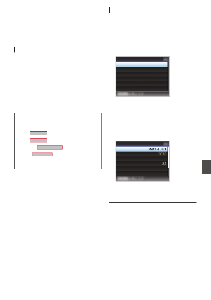
Importing Metadata
You can download a metadata settings file (XML
format) from the FTP server and store metadata in
the camera recorder.
The imported metadata is applied to clips to be
recorded.
Preparing Metadata
0
You can record the four metadata types below.
Title1 : ASCII
only,
max. 63 characters
(bytes)
Title2 : UNICODE, max. 127 bytes
Creator : UNICODE, max. 127 bytes
Description : UNICODE, max. 2047 bytes
0
Metadata makes use of the XML description
format.
0
Edit the
<Title1><Title2><Description><Creator> tag
element using the XML editor. (Indicated by the
frames below)
.
<?xml version="1.0" encoding="UTF-8"?>
<NRT-MetaInterface lastUpdate="2015-01-29T18:06:21+09:00"
xmlns="urn:schemas-proHD:nonRealTimeMetaInterface:ver.1.00"
xmlns:xsi="http://www.w3.org/2001/XMLSchema-instance">
<MetaData>
<Title1>Title1 sample</Title1>
<!-- only "en",max63bytes -->
<Title2>Title2 sample</Title2>
<!-- ,max127bytes -->
<Description>Description sample</Description>
<!-- ,max2047bytes -->
<Creator>Creator sample</Creator>
<!-- ,max127bytes -->
</MetaData>
</NRT-MetaInterface>
Configuring the Server for Downloading
For specifying the settings for connecting to the
FTP server for downloading the metadata (domain
name, user name, password, etc.) as well as the
path of the file to download.
1
Open the [Metadata Server] screen.
Open the [Network] B [Metadata Server]
screen.
.
Meta-FTP4...
Meta-FTP3...
Meta-FTP2...
Meta-FTP1...
Metadata Server
2
Register the [Metadata Server].
0
Select a server using the cross-shaped
button (JK), and press the Set button (R).
The server settings screen appears. Perform
setting for each item.
0
Up to 4 settings can be registered.
(A P139 [ Metadata Server ] )
.
Username
File Path
Port
Server
Protocol
Alias
Metadata Server Set
Memo :
0
For details on the registered information, please
consult the network administrator for the server.
Importing Metadata
189
Connecting to the Network
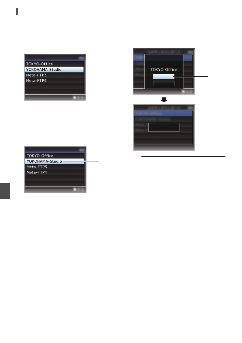
Importing Metadata
Download the metadata settings file (XML format)
from the FTP server.
1
Select [Network]
B [
Import Metadata] and
press the Set button (
R).
The [Import Metadata] screen appears.
.
Import Metadata
2
Select the server for importing the
metadata.
0
The name that is registered in
[Metadata
Server] B [Alias] is displayed.
0
Select a server using the cross-shaped
button (JK), and press the Set button (R).
.
2
Import Metadata
3
Select [Import] on the confirmation screen,
and press the Set button (
R).
Import starts.
After import is complete, the display is restored
to the screen before the [Import Metadata]
screen appears.
.
3
Importing...
Cancel
Import
Import Metadata?
Memo :
0
You cannot exit the menu or perform recording
while import is in progress.
0
If import of the metadata failed, “Import Error!” is
displayed, and a message indicating the cause
of the error appears.
Press the Set button (R) to return to the [Import
Metadata] screen in step 1.
(A P
219 [List of FTP Transfer Errors] )
0
When “HTTP” is selected in the [Select FTP
Proxy] screen of the network connection setting,
connections to the servers other than “FTP”
protocol cannot be made.
0
If a setting other than “FTP
” is specified for
[Protocol], to ensure the safety of the
communication path, a screen appears
prompting you to validate the fingerprint of the
public key and certificate received from the
server.
Check to ensure that the displayed value
coincides with the known value.
190
Importing Metadata
Connecting to the Network
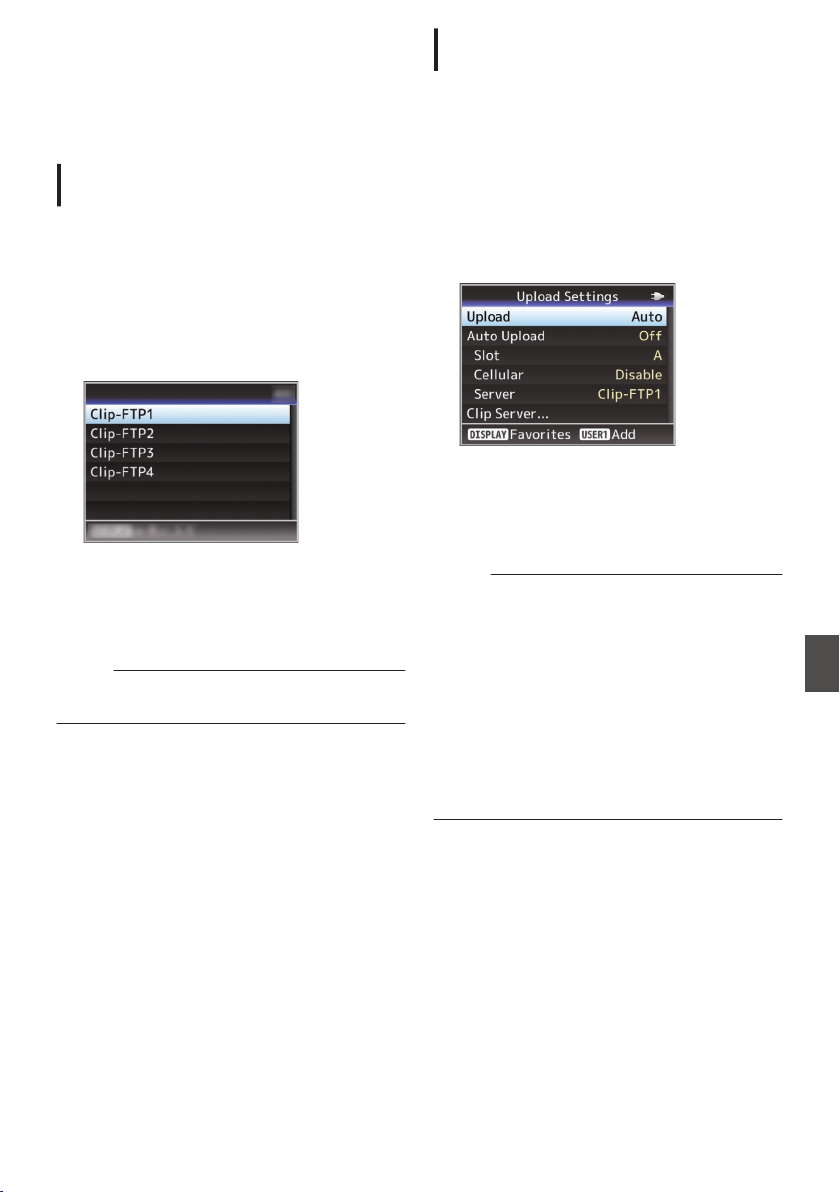
Uploading a Recorded
Video Clip
The following are steps to upload clips recorded in
a recording media to a preset FTP server.
Configuring the FTP Server for
Uploading
For specifying the settings for connecting to the
FTP server to upload recorded clips to (domain
name, user name, password, etc.) as well as the
directory of the upload destination.
1
Open the [Clip Server] screen.
Open the [Network] B [Upload Settings] B [Clip
Server] screen.
.
Clip Server
2
Register the [Clip Server].
Register the server to upload recorded clips in
the recording media to.
Up to 4 servers can be registered.
(A P146 [ Clip Server ] )
Memo :
0
For details on the registered information, please
consult the network administrator for the server.
Uploading Clips Automatically (Auto
FTP)0
The following are steps to automatically upload
clips recorded in a recording media to a preset FTP
server.
1
Configure the settings for automatic
upload
Configure [Network] B [Upload Settings] B
[
Upload] to “Auto” and configure the settings for
each of [Slot], [Cellular] and [Server].
(A P146 [ Upload ] )
.
2
Start uploading
0
Configuring [Network] B [Upload Settings] B
[Auto Upload] to “On” starts uploading.
0
You can also press the user button that is
assigned with
“Auto Upload”.
Memo :
0
FTP transfer is performed for the slot configured
in [Slot].
0
If recording is started for the same slot as the
one configured in [Slot] while FTP transfer is in
progress, FTP transfer will be interrupted.
0
FTP transfer is not performed while live
streaming or Return over IP is in progress.
0
FTP transfer is disabled when [System]
B
[Record Set] B [Record Format] B [System] is
configured to “High-Speed”2. To perform
FTP transfer, select a setting other than “High-
Speed”.
Uploading a Recorded Video Clip
191
Connecting to the Network
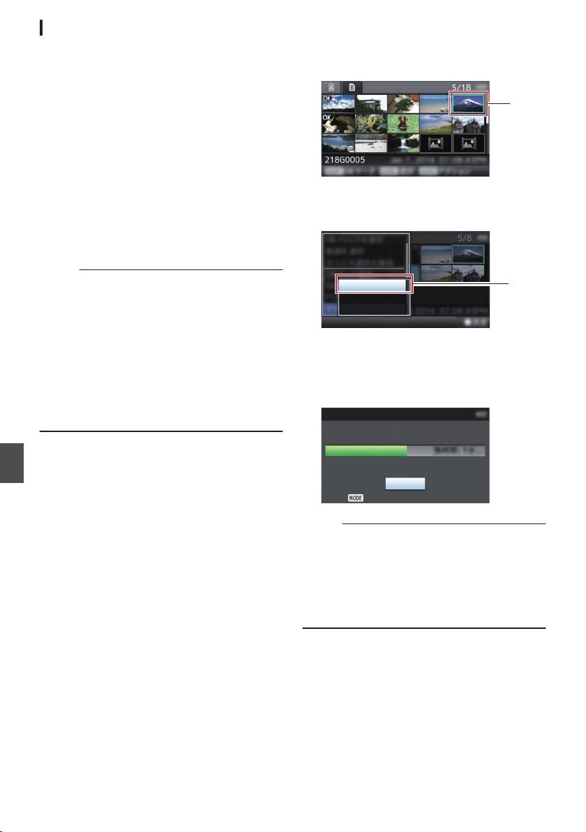
Uploading Clips Manually (Manual FTP)
The following are steps to upload clips recorded in
a recording media to a preset FTP server.
All playable clips on the thumbnail screen can be
uploaded.
1
Configure the FTP server for manual
uploading
Set [Network] B [Upload Settings] B [Upload]
to “Manual
”.
(A P146 [ Upload ] )
2
Register the [Clip Server].
0
Open the
[Network] B [Upload Settings] B
[Clip Server] screen.
0
Register the server to upload recorded clips
in the recording media to.
Up to 4 servers can be registered.
(A P
146 [ Clip Server ] )
Memo :
0
For details on the registered information, please
consult the network administrator for the server.
0
When [Network] B [Upload Settings] B [Upload]
is configured to “Auto”, manual uploading is also
disabled for slots other than the selected “Slot”.
To perform manual uploading, select “Manual”.
0
FTP transfer is disabled when
[System] B
[Record Set] B [Record Format] B [System] is
configured to “High-Speed”2. To perform
FTP transfer, select a setting other than “High-
Speed”.
Uploading a Video Clip
1
Set the camera recorder to the Media mode.
0
Press and hold the [CAM/MEDIA] selection
button in the Camera mode to enter the
Media
mode. A thumbnail screen of the clips
recorded on the SD card is displayed.
0
You can upload the selected clips on the
thumbnail screen to the FTP server.
(A P95 [Thumbnail Screen] )
2
Move the cursor to the clip to be uploaded.
Move the cursor to the clip to be uploaded using
the cross-shaped button (JKH I).
.
2
3
Press the [USER4] button.
The action selection screen is displayed.
.
All Clips
Selected Clips
This Clip
3
4
Select [FTP Upload]
B [This Clip] B server
to upload to, and press the Set button (
R).
The status of the transfer process is indicated
by a progress bar.
.
Upload in Background
Stop
FTP Upload
Memo :
0
The name for the server to upload files to are
indicated using the preset names in [Clip
Server] B [Alias].
0
To stop uploading, press the Set button (R).
Select
[Yes] on the confirmation screen, and
press the Set button (R) to stop uploading and
return to the thumbnail screen.
192
Uploading a Recorded Video Clip
Connecting to the Network
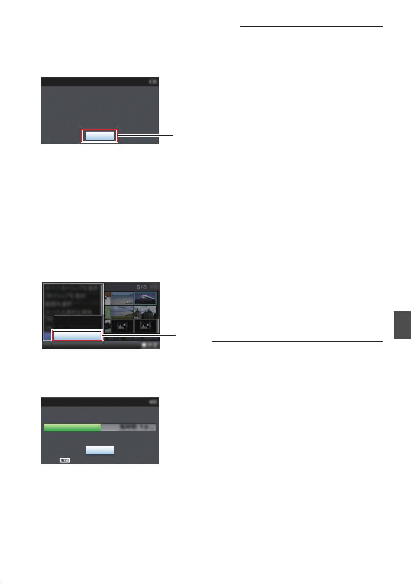
5
Upload is complete.
0
After upload is complete, “Successfully
Completed.” appears on the screen.
0
Press the Set button (R) to return to the
thumbnail screen.
.
5
Exit
Successfully Completed.
FTP Upload
Selecting and Uploading Multiple Clips
To select and upload multiple clips, refer to
“[Selecting and Performing Operations on Multiple
Clips] (A P 102)”.
Uploading All Video Clips
1
Press the [USER4] button.
The action selection screen is displayed.
2
Upload the clips.
Select [FTP Upload...] B [All Clips
] B server to
upload to, and press the Set button (R).
.
All Clips
Selected Clips
This Clip
2
3
Upload starts.
The status of the transfer process is indicated
by a progress bar.
.
Upload in Background
Stop
FTP Upload
Memo :
0
To stop uploading, press the Set button (R).
Select [Yes] on the confirmation screen, and
press the Set button (R) to stop uploading and
return to the thumbnail screen.
0
If the file to be uploaded has the same name as
an existing file in the FTP server, an overwrite
confirmation window appears.
0
When “HTTP” is selected in the [Select FTP
Proxy] screen of the network connection setting,
the overwrite confirmation window will not be
displayed and the existing file is overwritten.
0
Even after upload has started (FTP transfer in
progress) in step 3, pressing the [CAM/
MEDIA] button
switches the camera recorder to
the Camera mode, allowing you to start
shooting.
0
If a setting other than “FTP
” is specified for
[Protocol], to ensure the safety of the
communication path, a screen appears
prompting you to validate the fingerprint of the
public key and certificate received from the
server.
Check to ensure that the displayed value
coincides with the known value.
0
Fingerprint is a unique value that varies with
each public key and certificate.
0
For details of the fingerprint, please consult
the administrator of the server to be
connected.
(A P146
[ Clip Server ] )
0
When “HTTP” is selected in the [Select FTP
Proxy] screen of the network connection setting,
connections to the servers other than “FTP”
protocol cannot be made.
Uploading a Recorded Video Clip
193
Connecting to the Network
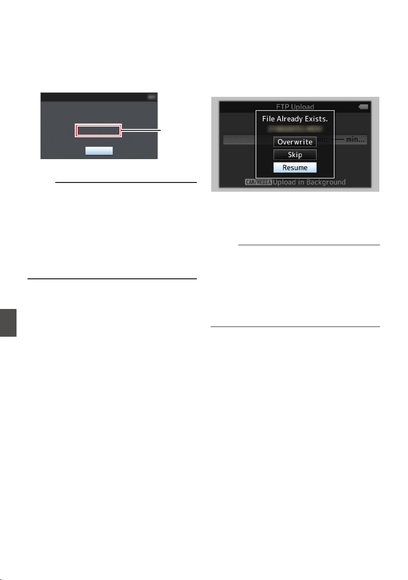
4
Upload is complete.
0
After all clips are uploaded successfully,
“Successfully Completed.” is displayed.
Press the Set button (R) to return to the
thumbnail screen.
0
When clips are not uploaded successfully,
the following errors are displayed.
.
Cause of
Error
Exit
Internal Error.
Failed.
FTP Upload
(A P
219 [List of FTP Transfer Errors] )
Memo :
0
If there is an error message or other notifications
when you switched to the Camera mode while
FTP upload is in progress, a 5 icon (yellow) will
appear in the remaining media space display
area in the Camera mode.
You can press the [CAM/MEDIA] button to
switch to the Media mode and display the above
error screen.
Follow “[List of FTP Transfer Errors] (A P 219)”
to clear the error message.
FTP Resume Feature
When FTP transfer starts and there is a file of the
same name on the server with a file size smaller
than the file to be transferred, the file on the server
will be regarded as an interrupted file during a FTP
transfer. A confirmation screen to resume transfer
(append writing) appears.
.
If “Resume” is
selected, FTP transfer is carried out
such that it appends from the position where it was
interrupted.
When FTP transfer ends normally, “Complete”
appears on the screen.
Memo :
0
FTP server equipped with resume function is
required.
0
If [Network] B [Upload Settings] B [Clip
Server] B [Clip-FTP1/2/3/4] B [Protocol] is set
to “SFTP”, the resume function is disabled.
0
If “HTTP
” is selected in the [Select FTP Proxy]
screen of the network connection setting, the
resume function is disabled.
194
Uploading a Recorded Video Clip
Connecting to the Network
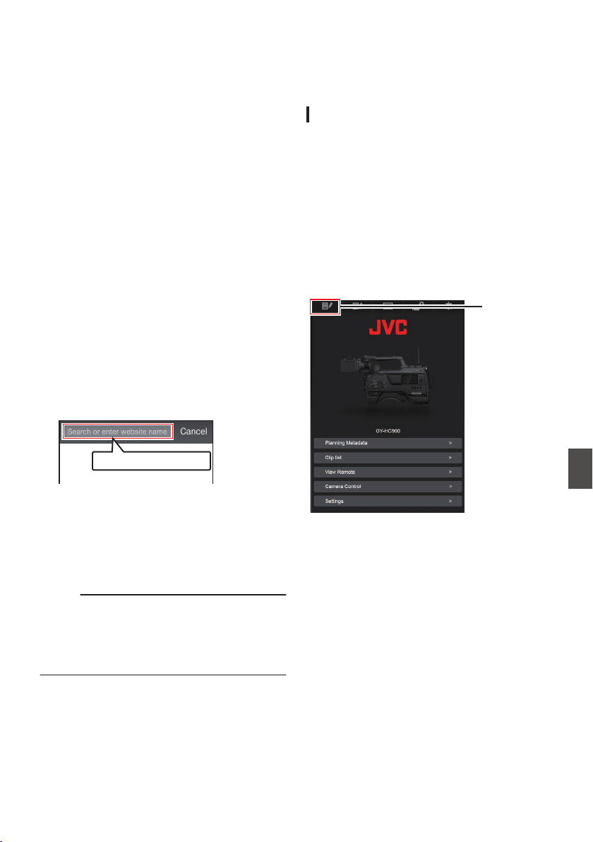
Connecting from a Web
Browser
You can access the web functions of this camera
recorder via a web browser on devices such as a
smartphone, tablet terminal, or PC.
Make the necessary preparations for connection in
advance.
(A P186 [Camera Setup for Network
Connection] )
1
Set the camera recorder to the Camera
mode, and display the status screen
([
LAN] or [USB/Int. WLAN] screen
u v
or [USB] screen
w x).
0
Press the [STATUS/SET
] button on the
camera recorder to display the status screen.
Press the cross-shaped button (HI) to
display the [LAN] or [USB/Int. WLAN] screen
u v, or [USB] screen w x.
0
Check the displayed
[IP Address].
2
Start up the web browser on the terminal
you wish to connect to the camera
recorder, and enter the [IP Address] in the
address field.
(Example: 192.168.0.10)
If “192.168.0.10” is displayed in [IP Address],
enter “http://192.168.0.10”.
.
http://192.168.0.10
3
Enter the user name and password.
Enter the user name and the password on the
login screen to display the main page of the
camera.
0
Check the [Web Username] and [Web
Password] in the [Network] screen (status
screen).
Memo :
0
The user name and password can be changed
in [Network] B [Web] B [Username] and
[Password].
(A P145
[ Username ] )
(A P145 [ Password ] )
Editing Metadata
You can create the metadata to be inserted into a
recorded file, or rewrite the metadata of a recorded
clip.
Planning Metadata
You can access the page for editing the camera
recorder’s
metadata
via a web browser on devices
such as a smartphone, tablet terminal, or PC, and
edit the metadata that is to be applied to clips to be
recorded.
1
Access the main page of the camera.
Access the page via a web browser on devices
such as a smartphone, tablet terminal, or PC.
(A P195
[Connecting from a Web Browser] )
2
Tap (click) the [Planning Metadata] tab to
open the [Planning Metadata] screen.
.
2
Connecting from a Web Browser
195
Connecting to the Network
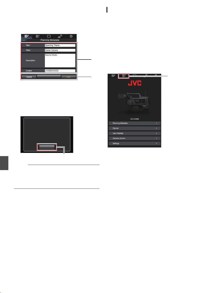
3
Edit the metadata.
A
Enter information for the necessary fields.
B
After input is complete, tap (click) [Save
] to
overwrite the metadata.
.
A
B
4
Tap (click) [
OK] on the confirmation screen.
0
Update of the [Planning Metadata] starts.
0
After update is complete, “Renewal of
planning metadata is succeeded.” is
displayed. Tap (click) [OK].
0
Returns to the screen in step 3.
.
4
OK
Renewal of planning metadata is
succeeded.
Memo :
0
If update failed, “Renewal of planning metadata
is failed.” is displayed.
Tap (click) [Close] to return to the screen of step
3.
Clip Metadata
You can access the page for editing the metadata
via a web browser on devices such as a
smartphone, tablet terminal, or PC, and display or
rewrite the metadata that is recorded to a clip.
1
Access the main page of the camera.
Access the page via a web browser on devices
such as a smartphone, tablet terminal, or PC.
(A P195
[Connecting from a Web Browser] )
2
Display the clip list.
Tap (click) the [Clip List] tab to display the clip
list.
.
2
3
Set the camera recorder to the “Remote
Edit Mode”.
You can switch to “Remote Edit Mode” from a
web browser or through operation of the
camera.
196
Editing Metadata
Connecting to the Network
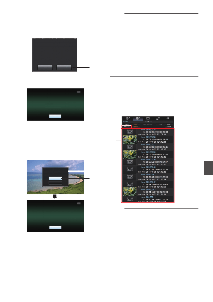
o
Switching from a web browser
A
You will see a message indicating
“It is
necessary to change the camera mode to
"Remote Edit Mode". Change the mode.”
on the web browser.
.
A
B
ChangeCancel
It is necessary to change the camera
mode to "Remote Edit Mode".
Change the mode.
B
Tap (click) [Change] to switch the camera
to the Remote Edit mode.
.
Exit
Remote Edit Mode
o
Switching from the camera
A
“Change to Remote Edit Mode?
” is
displayed on the display screen of the
camera unit.
B
Select [Change] and press the Set button
(R) to switch to the Remote Edit mode.
.
B
A
Exit
Remote Edit Mode
Cancel
Change
Remote Edit Mode?
Change to
Memo :
0
When the menu or status is displayed, display
of the confirmation screen will be put on hold.
0
If the menu is displayed on the camera recorder,
close the menu.
0
If the status is displayed on the camera recorder,
close the status display.
0
Pressing the Set button (R) on the camera
recorder while in the Remote Edit Mode ends
the Remote Edit Mode forcibly and switches to
the Camera mode.
0
When FTP upload via the camera unit is
currently in progress, switching to the Remote
Edit mode is disabled.
4
Select the Metadata Edit mode.
Select the [Metadata] tab.
5
Select the clip to rewrite the metadata.
0
A list of the recorded clips appears on the
[Clip List] screen.
0
Tap (click) the clip for which you want to
rewrite the metadata.
.
4
5
Memo :
0
You can switch the displayed slot using the [Slot
A] and [Slot B] tabs.
0
You
can use the [J-30] or [K+30] tab to jump to
the previous or next 30 clips on the list.
Editing Metadata
197
Connecting to the Network
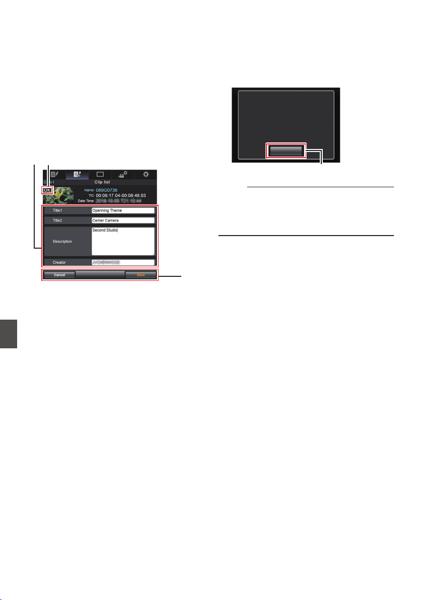
6
Edit the metadata of the selected clips.
A
Edit the information for the necessary fields.
0
If you are using a PC, input using the mouse
and keyboard.
0
If you are using a smartphone or tablet
terminal, tap the text input area to display a
standard software keyboard on the screen.
Enter the information using the displayed
keyboard.
B
You
can tap (click) [OK Mark] to add an OK mark
to or delete it from selected clips.
C
After editing is complete, tap (click) [Save] to
overwrite the metadata.
.
BA
C
7
Tap (click) [OK] on the confirmation screen.
0
Update of the metadata starts.
0
After update is complete, “Renewal of clip
metadata is succeeded.” is displayed. Tap
(click) [
OK].
0
Returns to the screen in step 4.
.
7
OK
Renewal of clip metadata is
succeeded.
Memo :
0
If update failed, “Renewal of clip metadata is
failed.” is displayed.
Tap (click) [Close] to return to the screen of step
4.
198
Editing Metadata
Connecting to the Network
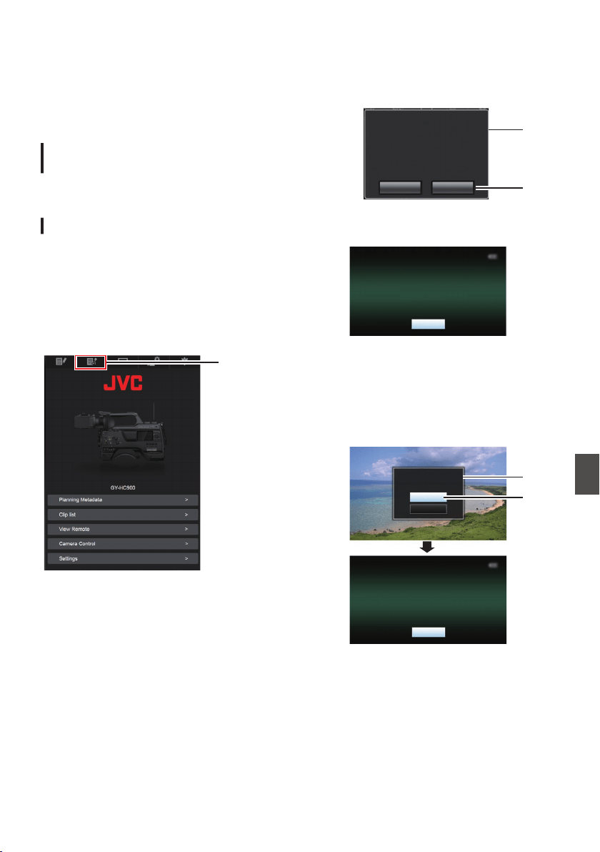
Uploading a Recording
Clip via a Web Browser
0
Upload
clips recorded in the SD card to a preset
FTP server.
0
You can upload selected clips, all clips, or those
appended with an OK mark.
Configuring the FTP Server for
Uploading
(A P191 [Configuring the FTP Server for
Uploading] )
Uploading Video Clips
1
Access the main page of the camera.
Access the page via a web browser on devices
such as a smartphone, tablet terminal, or PC.
(A P195 [Connecting from a Web Browser] )
2
Display the clip list.
Tap (click) the [Clip List] tab to display the clip
list.
.
2
3
Set the camera recorder to the “Remote
Edit Mode”.
You can switch to “Remote Edit Mode” from a
web browser or through operation of the
camera.
o
Switching from a web browser
A
You will see a message indicating
“It is
necessary to change the camera mode
to "Remote Edit Mode". Change the
mode.” on the web browser.
.
A
B
ChangeCancel
It is necessary to change the camera
mode to "Remote Edit Mode".
Change the mode.
B
Tap (click) [Change] to switch the
camera to the Remote Edit mode.
.
Exit
Remote Edit Mode
o
Switching from the camera
A
“Change to Remote Edit Mode?” is
displayed on the display screen of the
camera unit.
B
Select [Change] and press the Set button
(R) to switch to the Remote Edit mode.
.
B
A
Exit
Remote Edit Mode
Cancel
Change
Remote Edit Mode?
Change to
Uploading a Recording Clip via a Web Browser
199
Connecting to the Network
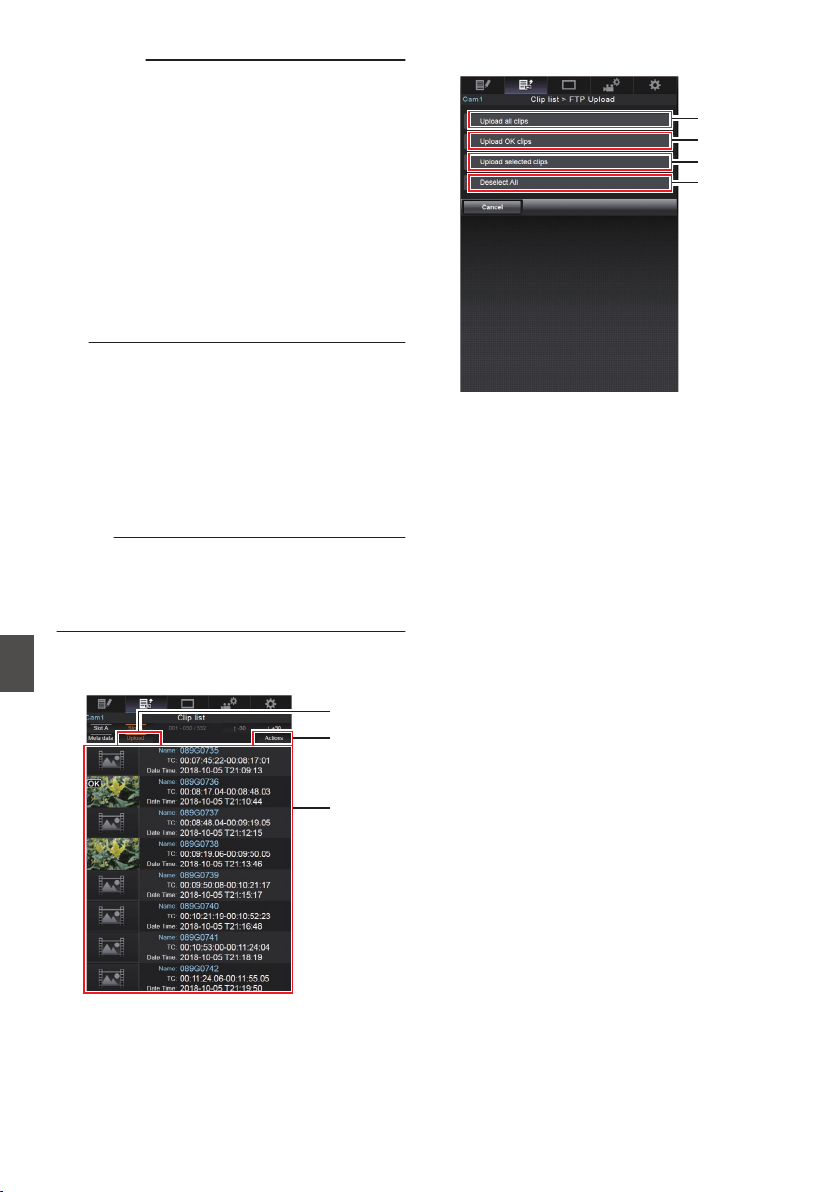
Memo :
0
When the menu or status is displayed,
display of the confirmation screen will
be put on hold.
0
If the menu is displayed on the camera
recorder, close the menu.
0
If
the status is displayed on the camera
recorder, close the status display.
0
Pressing the Set button (R) on the
camera recorder while in the Remote
Edit Mode ends the Remote Edit Mode
forcibly and switches to the Camera
mode.
0
When FTP upload via the camera unit
is currently in progress, switching to the
Remote Edit mode is disabled.
4
Select the Upload mode.
Select the [Upload] tab.
5
Select the clip you want to upload.
0
A list of the recorded clips appears on the
[Clip List] screen.
0
Tap (click) the clip you want to upload to
select it.
0
Clips being selected are indicated by a check
mark.
Memo :
0
You can switch the displayed slot using the [Slot
A] and [Slot B] tabs.
0
You
can use the [J-30] or [K+30] tab to jump to
the previous or next 30 clips on the list.
6
Select the upload operation.
Tap (click) the [Actions] button.
.
4
6
5
7
Select a method to upload the clips.
.
A
B
C
D
A
Upload all clips
Uploads all the clips in the displayed slots.
Tap (click) to move to the [Clip Server]
screen.
B
Upload OK clips
Uploads all clips in the displayed slots that
are appended with an OK mark.
Tap (click) to move to the [Clip Server]
screen.
C
Upload selected clips
Uploads the clips you have selected.
Tap (click) to move to the [Clip Server]
screen.
D
Clear all selection
Clears all clip selection and returns to the
[Clip List] screen.
200
Uploading a Recording Clip via a Web Browser
Connecting to the Network
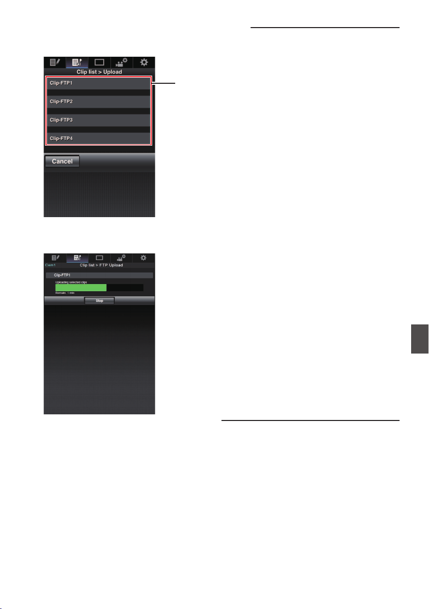
8
Select the clip server and start uploading.
0
Upon selecting the server to upoload clips to,
an upload screen appears.
.
8
0
The status of the transfer process is indicated
by a progress bar.
.
Memo :
0
To stop transfer, tap (click) the [Stop] button.
Tapping (clicking) [Yes] on the confirmation
screen stops the transfer halfway and brings you
back to the main page.
0
If there already exists a file on the FTP server
with
a name identical to the file to be transferred,
a confirmation screen asking to overwrite the file
will appear.
However, if “HTTP” is selected in the [Select
FTP Proxy] screen of the network connection
settings, an overwrite confirmation screen does
not appear, and the existing file will be
overwritten directly.
0
After
uploading in step 8 has started, other web
browser operations are disabled until uploading
is complete.
0
After uploading in step 8 has started and upon
shifting to the Media mode by pressing the
[CAM/MEDIA] selection button, operation from
the web browser will be disabled.
To enable web browser operation, press the
[CAM/MEDIA] selection button again to switch
to the Camera mode.
0
If a setting other than “FTP
” is specified for
[Protocol], to ensure the safety of the
communication path, a screen appears
prompting you to validate the fingerprint of the
public key and certificate received from the
server.
Check to ensure that the displayed value
coincides with the known value.
0
Fingerprint is a unique value that varies with
each public key and certificate.
0
For details of the fingerprint, please consult
the administrator of the server to be
connected.
(A P146
[ Clip Server ] )
0
When “HTTP” is selected in the [Select FTP
Proxy] screen of the network connection setting,
connections to the servers other than “FTP”
protocol cannot be made.
Uploading a Recording Clip via a Web Browser
201
Connecting to the Network
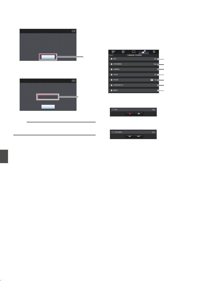
9
Upload is complete.
0
After upload is complete, “Successfully
Completed.” appears on the screen.
.
9
Exit
Successfully Completed.
FTP Upload
0
When clips are not uploaded successfully,
the following errors are displayed.
.
Cause of
Error
Exit
Internal Error.
Failed.
FTP Upload
(A P219 [List of FTP Transfer Errors] )
Memo :
0
Follow “[List of FTP Transfer Errors] (A P 219)”
to clear the error message.
View Remote Control and
Camera Control Functions
You can control the camera by accessing via a web
browser on devices such as a smartphone, tablet
terminal, or PC.
You can perform the following operations for each
of the items.
The image is displayed on the View remote.
.
A
B
C
D
E
F
G
A
REC
For performing recording start or recording
pause operation.
.
B
STREAMING
Turns on or off live streaming.
.
202
Uploading a Recording Clip via a Web Browser
Connecting to the Network
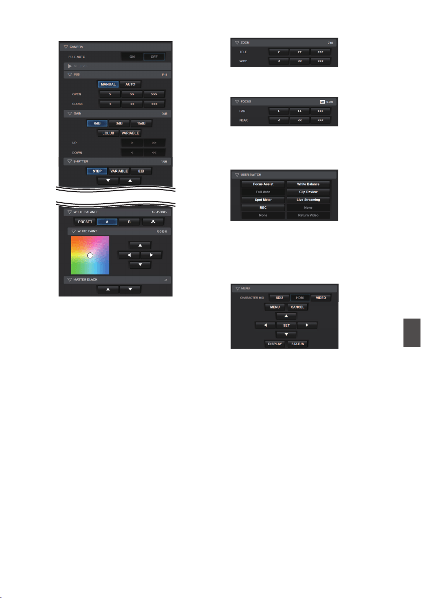
C
CAMERA
Enables operations related to the camera
functions.
.
.
D
ZOOM
Enables zooming operations.
.
E
FOCUS
Enables focusing operations.
.
F
USER SWITCH
You can enable or disable the user buttons that
are assigned with a function.
.
G
MENU
You can show or hide the display and menu
characters on an external monitor as well as
operation of menus, switching the display
screen and status display.
.
View Remote Control and Camera Control Functions
203
Connecting to the Network
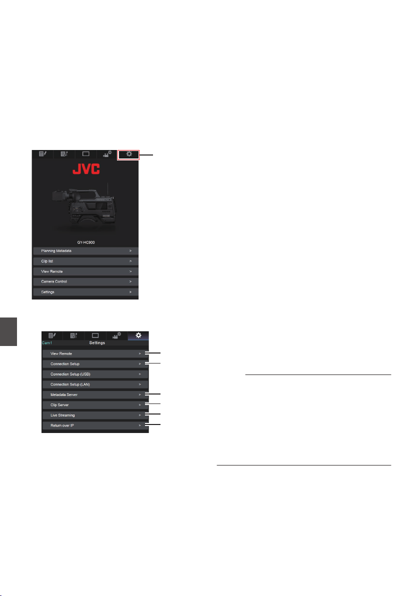
Changing the Settings via
a Web Browser
You can change the network-related settings by
accessing via a web browser on devices such as a
smartphone, tablet terminal, or PC.
1
Access the main page of the camera.
Access the page via a web browser on devices
such as a smartphone, tablet terminal, or PC.
(A P195
[Connecting from a Web Browser] )
2
Tap (click) the [Settings] tab.
.
2
3
The [Settings] screen appears.
Set each of the items as follows.
.
A
B
C
D
E
F
A
View Remote
Settings for operations on the View Remote.
B
Connection Setup
Settings related to the network.
You can change the settings for each of the
preset items on the [Wizard
] screen of the
camera recorder.
C
Metadata Server
Settings on the server for importing the
metadata.
Setting can be performed in the same way as
the Metadata Server menu on the camera
recorder.
The latest settings are reflected, regardless of
whether they are specified via the camera
recorder or web operation.
D
Clip Server
Settings for the server to upload recorded clips
to.
Setting can be performed in the same way as
the [Clip Server] menu on the camera recorder.
The latest settings are reflected, regardless of
whether they are specified via the camera
recorder or web operation.
E
Live Streaming
Setting for streaming audio and video via the
network.
The latest settings are reflected, regardless of
whether they are specified via the camera
recorder or web operation.
F
Return over IP
For specifying settings related to Return over IP.
For configuring settings for receiving video and
audio via the network.
The latest settings are reflected, regardless of
whether they are specified via the camera
recorder or web operation.
Memo :
0
Priority is given to menu operation on the
camera recorder.
0
When the menu on the camera recorder is
opened while the [Settings] screen is opened
using a web browser, a warning appears, after
which the display returns to the main screen.
0
While the menu is displayed on the camera
recorder, the [Settings] screen cannot be
opened via the web browser.
204
Changing the Settings via a Web Browser
Connecting to the Network
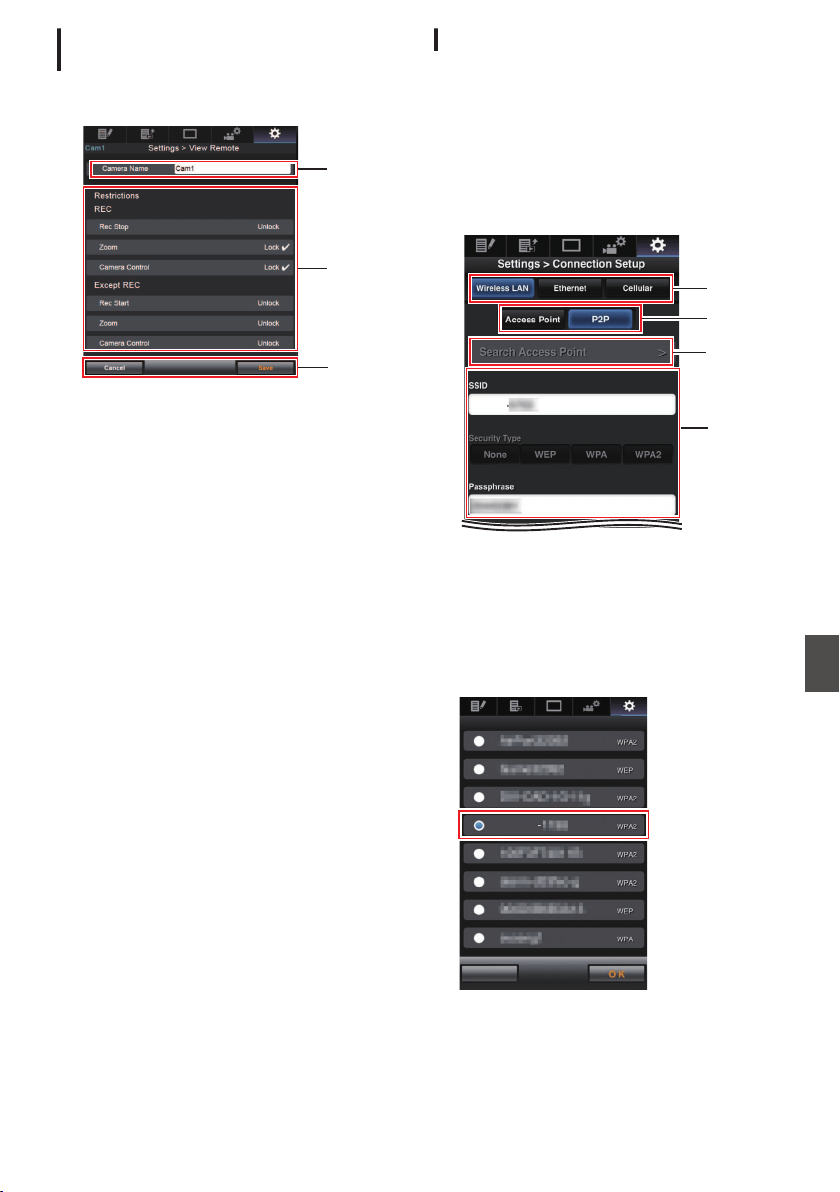
Changing View Remote Function
Settings
For performing setting for using the View Remote
function.
.
A
B
C
A
[Camera Name]
0
For setting the name that appears at the top
left of the view screen.
0
Tapping the text input area displays a
software keyboard.
If you are using a PC, enter using the PC
keyboard.
0
By tapping
the Go key after input is complete,
the software keyboard disappears.
B
[Restrictions]
For setting the buttons to be disabled on the
View screen while in the locked mode.
0
[REC]:
For setting whether to disable the Stop
Record button, zoom operation, and camera
control during recording.
Tap (click) each item to switch between
[Unlock] and [Lock].
0
[Except REC]
:
For setting whether to disable the record
button, zoom operation, and camera control
in any mode other than the recording mode.
Tap (click) each item to switch between
[Unlock] and [Lock].
C
[Save]/[Cancel]
Tap (click) [Save] to save the settings.
Tap (click) [Cancel] to stop setting and return to
the main [Settings] screen.
Changing Connection Setup
You can change the settings for each of the preset
items on the [Wizard] screen of the camera
recorder.
0
If all the items cannot be displayed in a single
page, scroll down to display the remaining
items.
0
Items that cannot be changed are grayed out
according to the type of adapter connected and
the mode of connection.
.
HC900
A
D
C
B
A
Type of Adapter Connected
B
Mode of Wireless LAN Connection
C
[Search Access Point] Button
Tap (click) to display a list of the detected
access points.
The currently selected access point is indicated
by a dot mark ( 0 ).
.
Cancel
Search Access Point
HC900
Changing the Settings via a Web Browser
205
Connecting to the Network
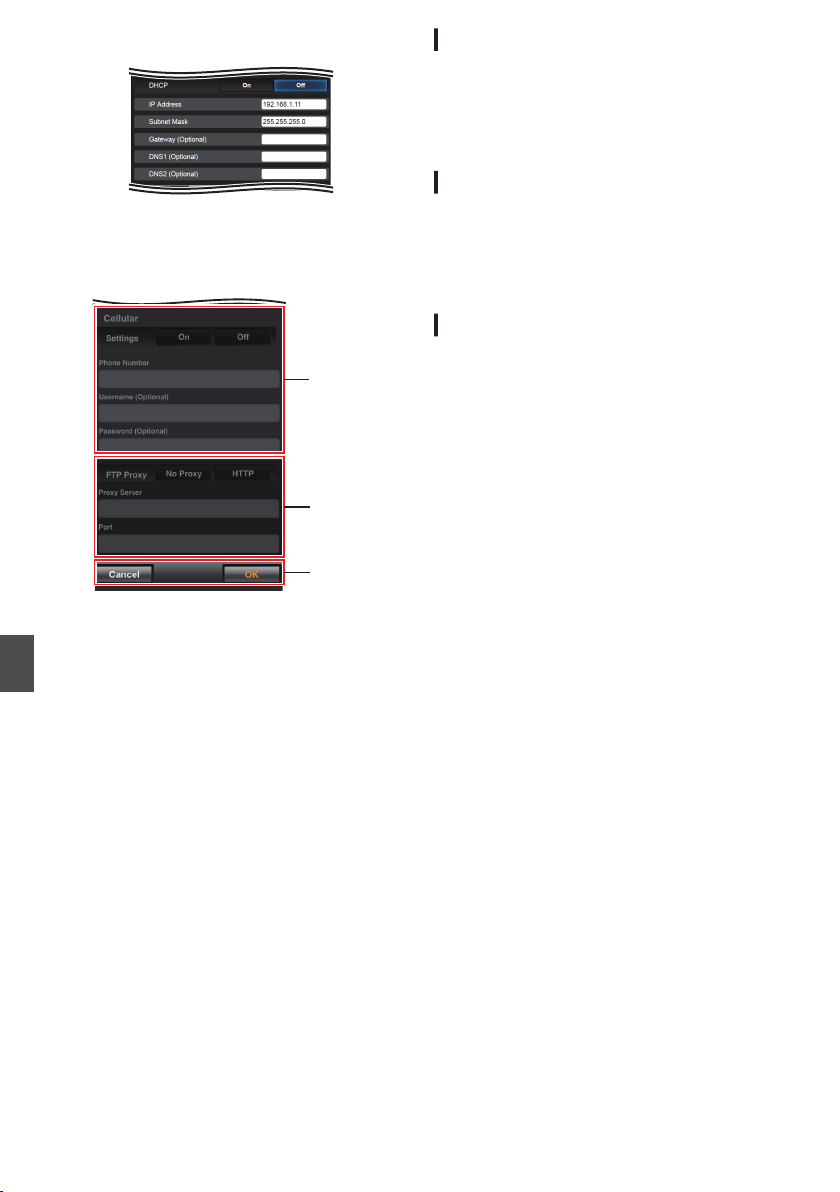
D
Settings on the [Select Setup Type] Screen
.
E
Settings on the [IP Address Configuration]
Screen
When “DHCP
” is selected, all items will be
grayed out.
.
F
G
H
F
Settings when using cellular adapter
G
Settings on the [Select FTP Proxy] Screen
H
[OK]/[Cancel] Button
After changing of settings is complete, tap
(click) the [OK] button.
On the confirmation screen, tap (click)
[Execute] to change the settings on the camera
recorder and restart the network.
Changing Metadata Server Settings
You can make direct changes to the FTP server for
importing the metadata set in [Network] B
[Metadata Server], as well as the path of the file to
import.
(A P145 [Metadata Server Item] )
Changing Clip Server Settings
You can make direct changes to the server and
directory settings that are specified in [Network] B
[Clip Server] for uploading recorded clips in the
recording media to the FTP server.
(A P146 [ Clip Server ] )
Changing Streaming Settings
You can make direct changes to settings that are
specified in [Network] B [Live Streaming], such as
information on the destination of distribution.
(A P141 [Live Streaming Item] )
206
Changing the Settings via a Web Browser
Connecting to the Network
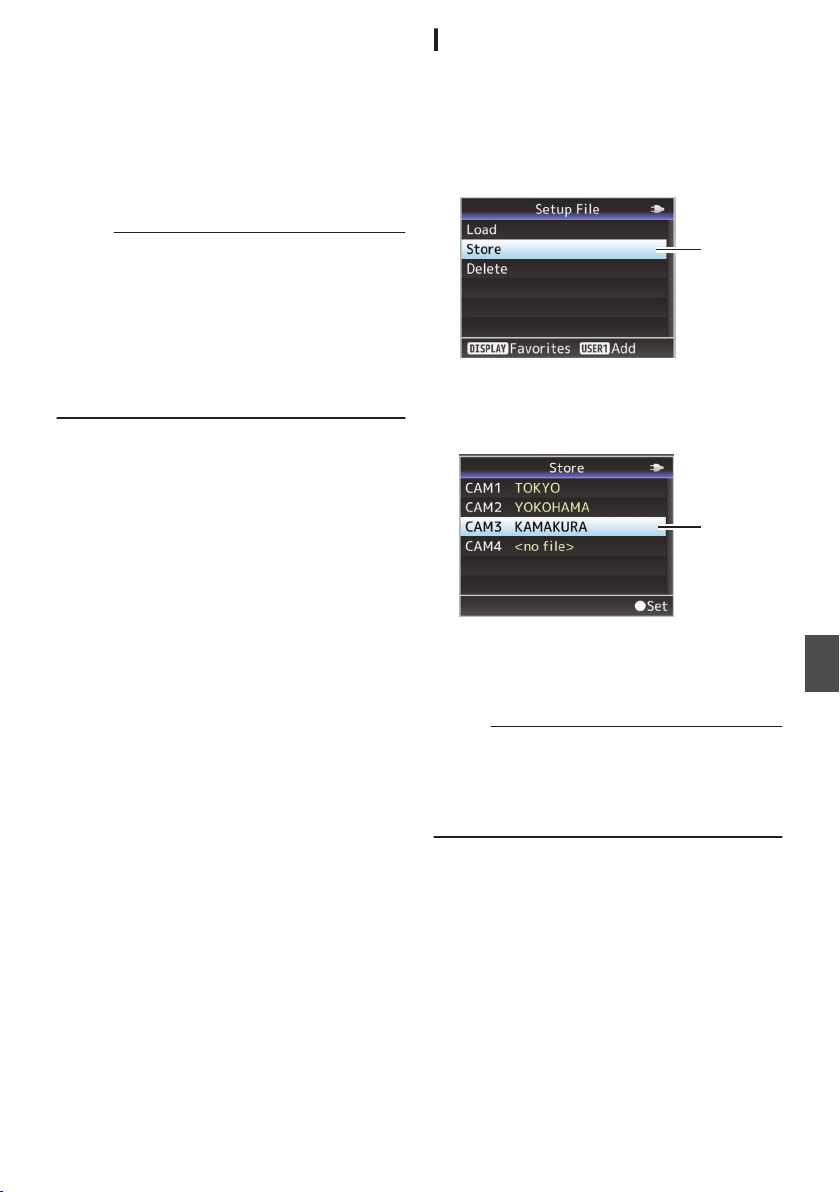
Managing the Network
Connection Settings File
This camera recorder allows you to save the
network connection settings on the Wizard screen
to the camera recorder unit.
Loading a saved connecting settings file enables
you to reproduce the appropriate network
connection state speedily.
Memo :
0
To save or retrieve the connection settings, go
to [Network] B [Connection Setup].
0
The following operations can be performed on
the [Connection Setup] menu.
0
[Saving the Connection Settings File]
(A P 207)
0
[Reading the Connection Settings File]
(A P 208)
0
[Deleting Connection Settings] (A P 209)
Number of Storable Setup Files
Camera recorder : [CAM1] to [CAM4]
Saving the Connection Settings File
1
Select [Network]
B [Connection Setup] B
[Setup File]
u v / [USB Setup
File]
w x and press the Set button
(
R).
2
Select [Store]
and press the Set button (
R).
.
2
3
Select the file to be newly saved (or
overwritten) using the cross-shaped
button (
JK), and press the Set button (R).
.
3
4
Name the file.
Enter the subname using the software
keyboard.
(A P107 [Text Input with Software Keyboard] )
Memo :
0
When overwriting an existing file, the subname
of the existing file is displayed.
0
Select [Cancel] and press the Set button (R), or
press the [CANCEL/RESET] button to return to
the previous screen.
Managing the Network Connection Settings File
207
Connecting to the Network
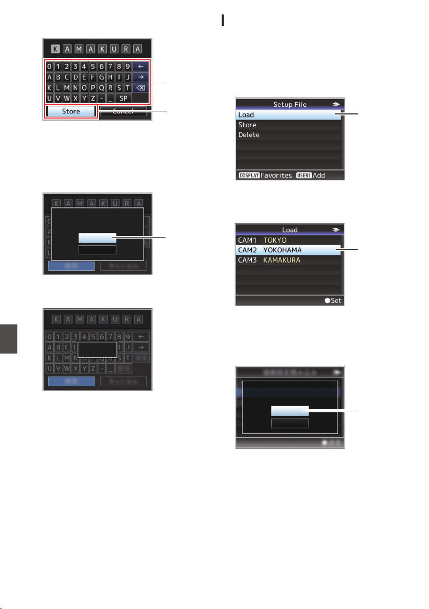
5
Select [Store] and press the Set button (
R).
.
5
4
6
Save the file.
0
A confirmation screen appears when you
choose to overwrite.
Select [Overwrite] on the confirmation
screen,
and
press the Set button (R). Saving
starts, and “Storing...” appears on the screen.
.
:KAMAKURA
6
Cancel
Overwrite
CAM3
Setup?
Overwrite Connection
0
Saving starts, and “Storing...” appears on the
screen when the file is newly saved.
.
Storing...
7
Saving is complete.
After saving of the file is complete, “Complete”
appears on the screen, and the menu screen
closes automatically.
Reading the Connection Settings File
1
Select [Network]
B [Connection Setup] B
[Setup File]
u v / [USB Setup
File]
w x and press the Set button
(
R).
2
Select [Load] and
press the Set button (
R).
.
2
3
Select the file to read using the cross-
shaped button (
JK), and press the Set
button (
R).
.
3
4
Select [Load] on the confirmation screen,
and press the Set button (
R).
Loading starts, and “Loading...” appears on the
screen.
.
:YOKOHAMA
4
Cancel
Load
CAM2
Setup?
Load Connection
5
Reading is complete.
After reading of the file is complete, “Complete”
appears on the screen, and the menu screen
closes automatically.
208
Managing the Network Connection Settings File
Connecting to the Network
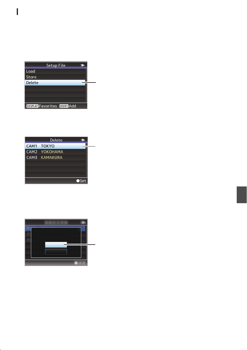
Deleting Connection Settings
1
Select [Network]
B [Connection Setup] B
[Setup File]
u v / [USB Setup
File]
w x and press the Set button
(
R).
2
Select [Delete] and press the Set button
(
R).
.
2
3
Select the file to delete using the cross-
shaped button (
JK), and press the Set
button (
R).
.
3
4
Select [Delete] on the confirmation screen,
and press the Set button (
R).
Deletion starts, and “Deleting...” appears on the
screen.
.
:TOKYO
4
Cancel
Delete
CAM1
Setup?
Delete Connection
5
Deletion is complete.
After file deletion is complete, “Complete”
appears on the screen.
Managing the Network Connection Settings File
209
Connecting to the Network
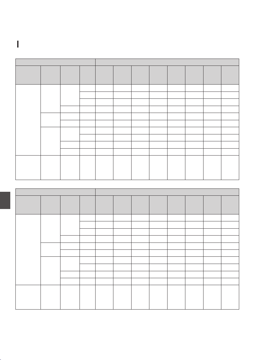
Performing Live Streaming
By combining with the decoder or PC application that supports live streaming, you can perform audio and
video streaming via the network.
Supported Formats
0
.
Record Format Usable Formats for Live Streaming
System Format Resolution Frame
Rate
1920x
1080,
60p
1920x
1080,
60i
1920x
1080,
30p
1280x
720,
60p
1280x
720,
30p
720x480,
60i
2
640x360,
60p
2
640x360,
30p
2
HD
HD(SDI In)
QuickTime
(H.264)
1920x
1080
60p
cccccccc
60i -
c
c
*
c
*
c
*
c
c
*
c
*
30p - -
c
*
-
c
*
--
c
*
1280x720 60p - - -
ccccc
Exchange
(U model)
1920x1080
60p
cccccccc
1280x720 60p - - -
ccccc
QuickTime
(MPEG2)
MXF
(MPEG2)
1920x
1080
60i -
c
c
*
c
*
c
*
c
c
*
c
*
30p - -
c
*
-
c
*
--
c
*
1440x1080
60i -
c
c
*
c
*
c
*
c
c
*
c
*
1280x720 60p - - -
ccccc
SD
SD(SDI In)
2
(U model)
QuickTime
(H.264)
720x480 60i - - - - -
c
--
.
1920x
1080,
50p
1920x
1080,
50i
1920x
1080,
25p
1280x
720,
50p
1280x
720,
25p
720x576,
50i
2
640x360,
50p
2
640x360,
25p
2
1920x
1080
50p
cccccccc
50i -
c
c
*
c
*
c
*
c
c
*
c
*
25p - -
c
*
-
c
*
--
c
*
1280x720 50p - - -
ccccc
1920x1080
50p
cccccccc
1280x720 50p - - -
ccccc
1920x
1080
50i -
c
c
*
c
*
c
*
c
c
*
c
*
25p - -
c
*
-
c
*
--
c
*
1440x1080
50i -
c
c
*
c
*
c
*
c
c
*
c
*
1280x720 50p - - -
ccccc
720x576 50i - - - - -
c
--
Record Format Usable Formats for Live Streaming
System Format Resolution Frame
Rate
HD
HD(SDI In)
QuickTime
(H.264)
MP4
(E model)
QuickTime
(MPEG2)
MXF
(MPEG2)
SD
SD(SDI In)
2
(E model)
QuickTime
(H.264)
* Not selectable when the setting is configured to HD(SDI In) or SD(SDI In).
210
Performing Live Streaming
Connecting to the Network

Memo :
0
The distributable resolution, frame rate and bit
rate vary according to the recording format.
0
To distribute progressive video, set the frame
rate to any of the progressive frame rates. And
to distribute interlace video, set the frame rate to
any of the interlace frame rates.
0
The following constraints apply depending on
the setting of [Network] B [Live Streaming] B
[Type].
0
A bit rate not exceeding maximum 12 Mbps
can be configured when
[Type] is set to
“RTSP/RTP”.
0
When [Type] is set to
“ZIXI”, a bit rate not
exceeding maximum 12 Mbps can be
configured regardless of the [Latency]
setting.
0
Depending on the type of network adapter
used and the connection, the images and
audio sound during live streaming can be
choppy.
Audio
AAC
Supported Protocols
MPEG2-TS/UDP
MPEG2-TS/TCP
MPEG2-TS/RTP
RTSP/RTP
ZIXI
RTMP
Performing Live Streaming
211
Connecting to the Network
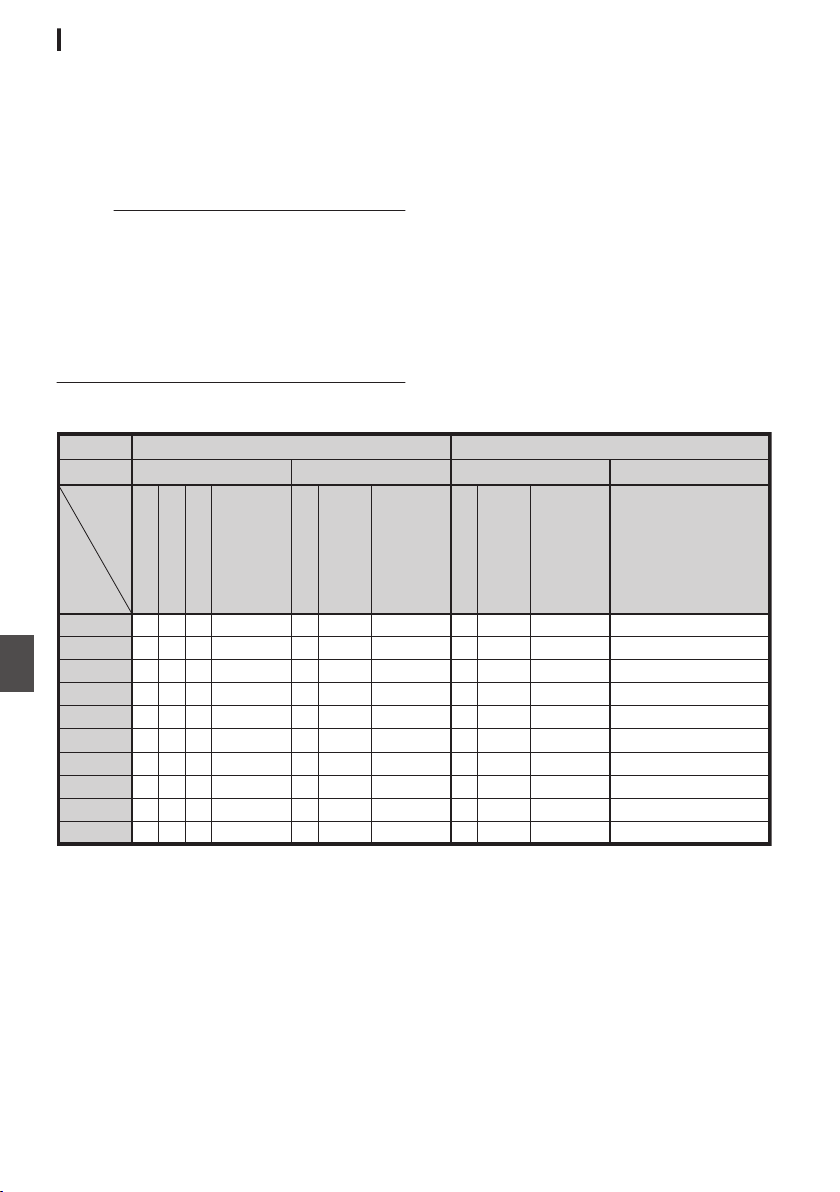
Setting Distribution
1
Set the [Record Format] according to the
resolution and frame rate of the video to be
distributed.
For details on the [Record Format] settings,
please refer to [Distributable [Record Format]
and [Live Streaming Set] Combinations]
(A P 212).
Memo :
0
Live streaming cannot be performed in the
following cases.
0
[System] B [Record Set] B [Record Format]
B [System] set to “HD+Web”2 or “High-
Speed”2.
0
When [
System] B [Record Set] B [Record
Format] B[WFrame Rate] is set to
“24p”2
2
Set the Resolution and Frame & Bit Rate for
the video to be distributed.
Specify the settings in [Network] B [Live
Streaming].
(A P
141 [Live Streaming Item] )
3
Specify the distribution protocol and
related items.
Specify the distribution protocol and related
items in
[Network] B [Live Streaming] B
[Streaming Server].
(A P141 [ Streaming Server ] )
4
Select the server for live streaming.
Select the distribution server in [Network] B
[Live Streaming] B [Server].
Distributable [Record Format] and [Live Streaming Set] Combinations
.
RR
RR
R
R
R
R
R
R
R
R
R
R
R
R
R
R
R
R
R
R
R
R
R
R
R R RRR R
R
R
R
R
R
R
R
R
R
RR
R
R
R
24 Mbps
60p, 50p
1920 x 1080
60i, 50i, 30p, 25p 60p, 50p
1280 x 720
30p, 25p
MPEG2-TS/UDP
MPEG2-TS/TCP
MPEG2-TS/RTP
RTSP
ZIXI
RTMP
MPEG2-TS/UDP
MPEG2-TS/TCP
MPEG2-TS/RTP
RTSP
ZIXI
RTMP
MPEG2-TS/UDP
MPEG2-TS/TCP
MPEG2-TS/RTP
RTSP
ZIXI
RTMP
MPEG2-TS/UDP
MPEG2-TS/TCP
MPEG2-TS/RTP
RTSP
ZIXI
RTMP
20 Mbps
16 Mbps
12 Mbps
8 Mbps
5 Mbps
3 Mbps
1.5 Mbps
0.8 Mbps
0.3 Mbps
Frame Rate
Resolution
Ty pe
Bitrate
* R: Distributable
212
Performing Live Streaming
Connecting to the Network
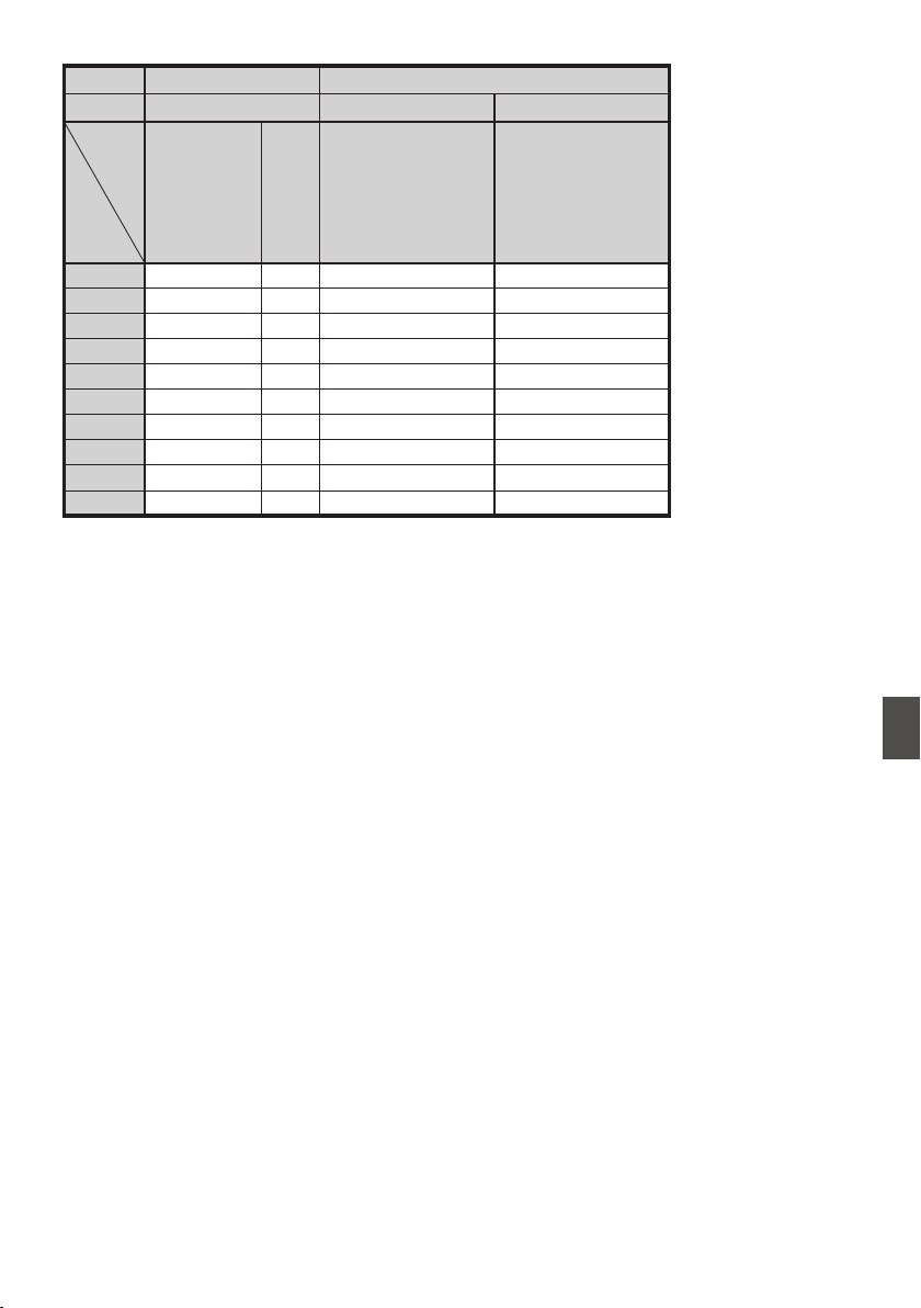
2
.
R
R
R
R
R
R
R
R
R
R
R
R
R
R
R
R
R
24 Mbps
60i or 50i
720 x 480 or 720 x 576
60p, 50p 30p, 25p
640 x 360
MPEG2-TS/UDP
MPEG2-TS/TCP
MPEG2-TS/RTP
RTSP
ZIXI
RTMP
MPEG2-TS/UDP
MPEG2-TS/TCP
MPEG2-TS/RTP
RTSP
ZIXI
RTMP
MPEG2-TS/UDP
MPEG2-TS/TCP
MPEG2-TS/RTP
RTSP
ZIXI
RTMP
20 Mbps
16 Mbps
12 Mbps
8 Mbps
5 Mbps
3 Mbps
1.5 Mbps
0.8 Mbps
0.3 Mbps
Frame Rate
Resolution
Ty pe
Bitrate
* R: Distributable
Performing Live Streaming
213
Connecting to the Network
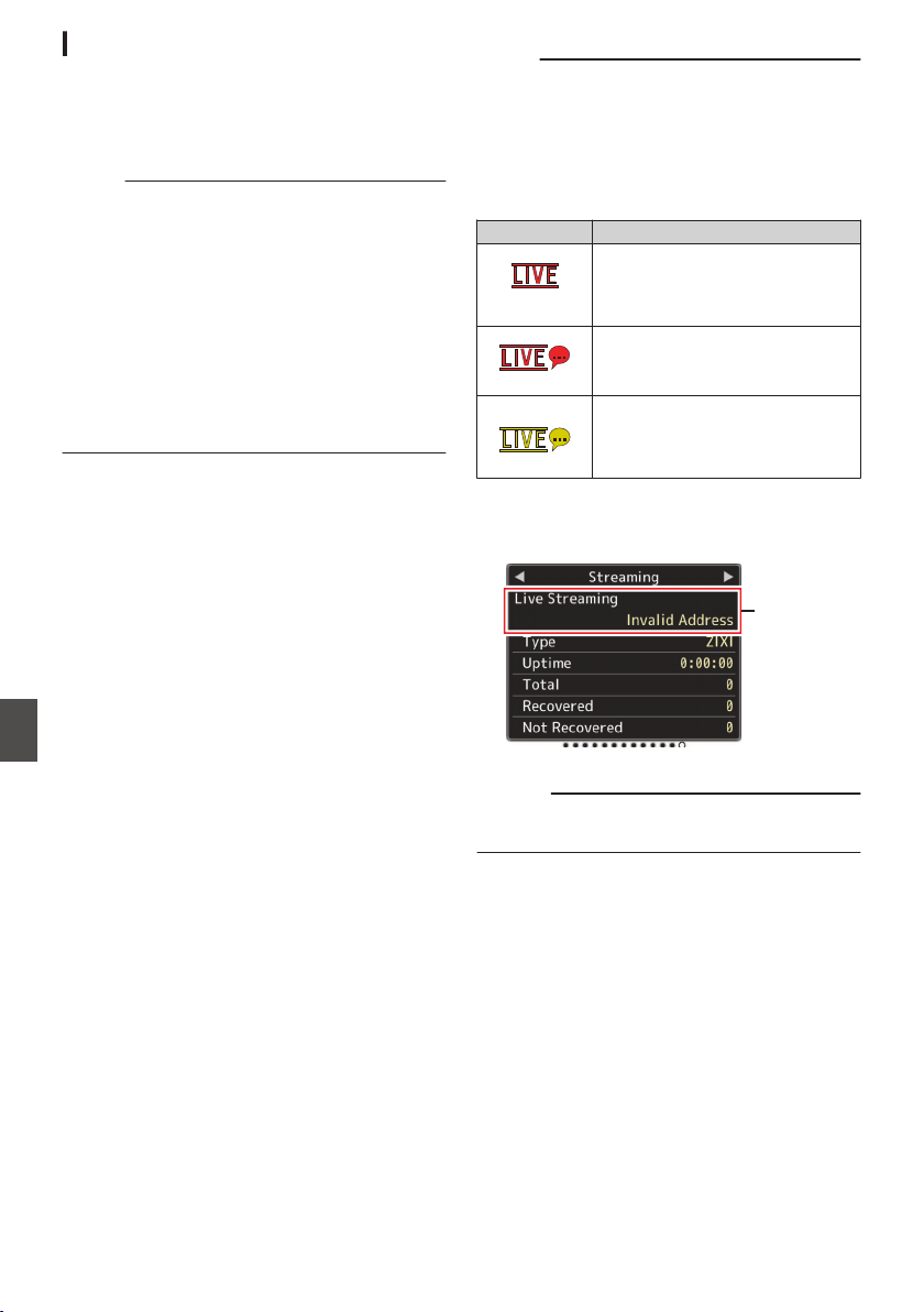
Starting Distribution
1
Perform the necessary setting for the
decoder and PC application.
For details on the settings, please refer to the
“INSTRUCTIONS” of the respective devices
and applications.
Memo :
0
If there is an NAT router within the
communication path between the camera and
the decoder, port forwarding setup is required.
For details on the settings, please refer to the
“INSTRUCTIONS” of the router in use.
0
The following parameters are required when
connecting to this camera recorder using the
RTSP/RTP.
Port number: 554
Stream ID: stream
0
Use the following to access via URL.
rtsp://<IP address of the camera recorder>:554/
stream
2
With the network connection established,
set [Live Streaming] to “On”.
(A P186 [Preparing Network Connection] )
0
Set [Network] B [Live Streaming] B [Live
Streaming] to “On”.
0
The
network connection mark appears on the
display screen when a network connection is
established.
(A P164 [Network Connection Icon] )
Memo :
0
You can also assign “Live Streaming” to a user
button.
(A P45 [Assignment of Functions to User
Buttons] )
0
You can view the status of distribution on the
LCD monitor.
(A P166 [Live streaming mark] )
Icon Status
.
(Red)
Distribution in progress (good
connection quality)
Blinks when distribution starts or
stops
.
(Red)
Distribution in progress (poor
connection quality)
.
(Yellow)
Waiting for connection (during
RTSP/RTP) or connection failed
0
When the 5 icon is displayed, you can view the
details of the error on the [Streaming] screen of
the status screen.
.
Cause of Error
(A P221 [List of Live Streaming Error Displays] )
Caution :
0
Streaming may be interrupted temporarily 24
hours after the process started.
214
Performing Live Streaming
Connecting to the Network
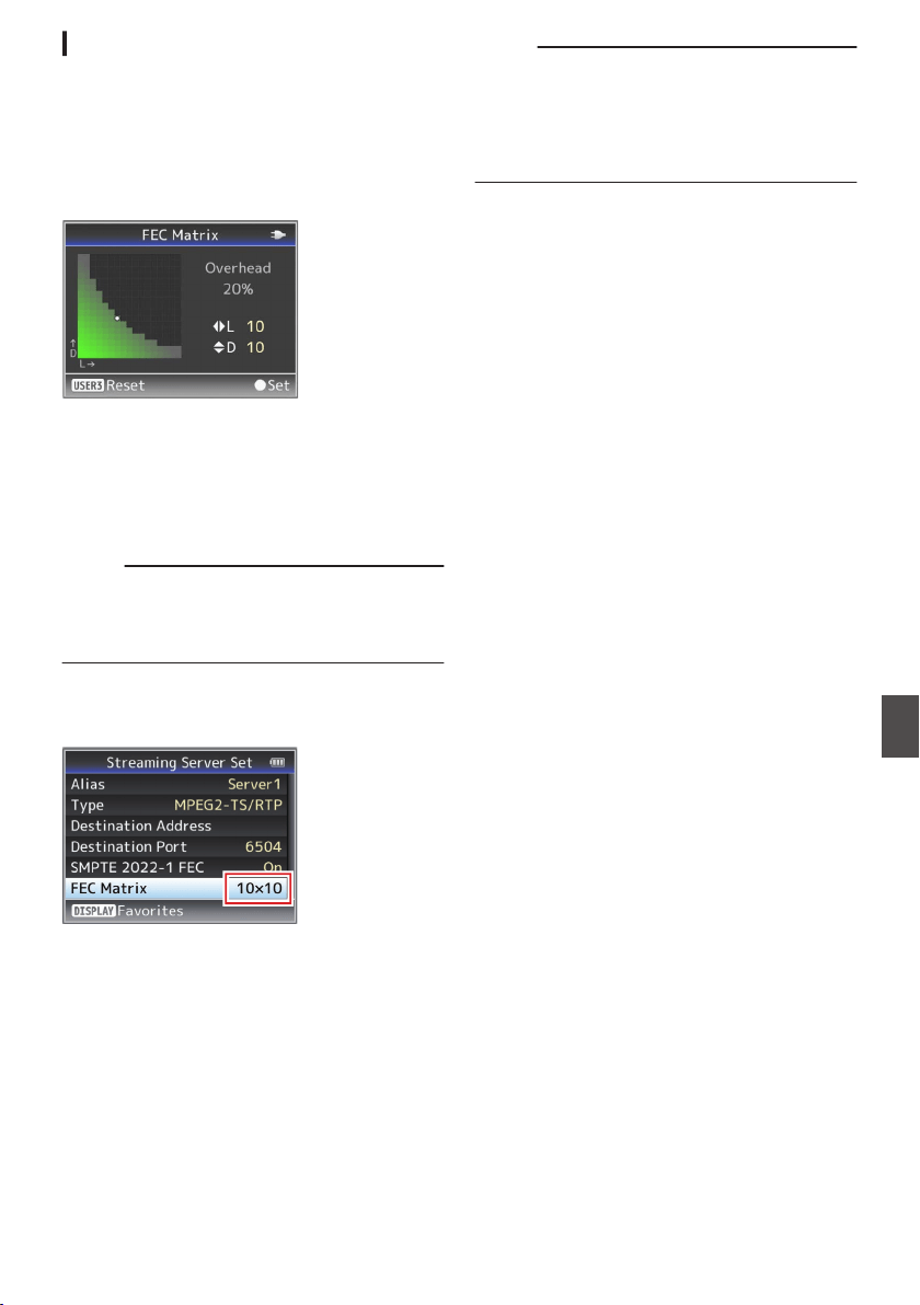
Setting the FEC Matrix 0
Set the amount of FEC (Forward Error Correction)
overhead for configuring SMPTE2022-1.
1
Select [Network]
B [Live Streaming
]
B
[Streaming Server]
B [Server1] to [Server4]
B [FEC Matrix] and press the Set button.
The FEC adjustment screen appears.
.
2
Adjust the L and D values.
Use the H/I buttons to adjust the L value, and
the J/K buttons to adjust the D value.
The amount of FEC overhead changes when
the L and D values are changed.
To restore the L and D values to their default
values, press the [USER3] button.
Memo :
0
Setting range
0
4 ≦ L ≦ 20 (Default value: L = 10)
0
4 ≦ D ≦ 20 (Default value: D = 10)
0
L × D ≦ 100 (Default value: L×D = 10×10)
3
Press the Set button (
R).
The screen returns to the streaming server
setting screen.
.
Memo :
0
Increasing the amount of FEC overhead
increases the packet loss resilience but more
network bandwidth is used.
0
Even with the same amount of overhead,
increasing the L value will increase the packet
loss (continuous packet loss) resilience.
Performing Live Streaming
215
Connecting to the Network

Return Video/Audio from
the Network (Return over
IP)0
Return video/audio from the network can be
displayed on the viewfinder or LCD monitor of the
camera or listened through a headphone.
Memo :
0
This feature is only usable in the Camera mode.
0
Start the encoder before activating Return over
IP. To end, turn off Return over IP before shutting
down the encoder.
0
This feature is available when [System] B
[Record Set] B [Record Format] B [System] is
set to “HD” or “SD”2. When [WFrame Rate]
is set to “24p”, this feature is not available.
Configuring the Return over IP Server
Configure the Return over IP settings and establish
the connection before displaying the return video.
1
Register the [Return Server].
Configure [Network] B [
Return over IP] B
[Server] to “Server”.
Configure the individual settings in the [Return
Server] item.
Memo :
0
For details on the registered information, please
consult the network administrator for the server.
0
Configure “Icecast” to a setting other than
[Type].
Operates as IFB when the setting is configured
to “Icecast”.
Return Video and Audio from the
Network
1
Set the camera recorder to the Camera
mode.
(A P20 [Operation Modes] )
2
Assign the “Return Video” and “Return
over IP” features to any of the user buttons
(A P
45 [Assignment of Functions to User
Buttons] )
Memo :
0
The “Return over IP” feature can also be
operated using “On”/“Off” under [Network] B
[Return over IP] B [Return over IP].
3
Configure the input destination of the
return video to “Network”
To specify the input destination of the return
video, configure [A/V Set] B [Video Set] B
[Return Input] to “Network”.
(A P135 [ Return Input 0 ] )
Memo :
0
When [System] B [Record Set] B [Record
Format] B [System] is configured to “HD(SDI
In)” or “SD(SDI In)”2, “---” is displayed and
the setting cannot be configured.
4
Select the aspect ratio of the return video.
Set using [A/V Set] B [Video Set] B [Return
Aspect].
(A P
135 [ Return Aspect ] )
5
Press
the user button that is assigned with
the “Return over IP
” function.
When Return over IP is activated, the settings
in [A/V Set] B [Audio Set] B [IFB/RET Monitor]
will be applied to the audio.
(A P138 [ IFB/RET Monitor... 0 ] )
6
Select the way the return video is to be
displayed.
Select in [Camera Function] B [User Switch
Set] B [Return Video]. The camera will operate
according to the setting.
(A P114 [ Return Video ] )
7
Press the user button that is assigned with
the “Return Video” function.
By pressing the user button assigned with the
“Return Video” function, the captured image or
return video is displayed according to the
method specified in step 6.
216
Return Video/Audio from the Network (Return over IP)0
Connecting to the Network

IFB (Return Audio)0
Return audio from the network can be played
through a headphone.
Memo :
0
This feature is only usable in the Camera mode.
0
Start the encoder before activating Return over
IP. To end, turn off Return over IP before shutting
down the encoder.
0
This feature is available when [System] B
[Record Set] B [Record Format] B [System] is
set to “HD” or “SD”2. When [WFrame Rate]
is set to “24p”, this feature is not available.
Configuring the Return over IP Server
Configure the Return over IP settings and establish
the connection before displaying the return video.
1
Register the [Return Server].
Configure [Network] B [
Return over IP] B
[Server] to “Server”.
Configure the individual settings in the [Return
Server] item.
Memo :
0
For details on the registered information, please
consult the network administrator for the server.
0
Configure “Icecast” to [Type].
Operates as IFB when the setting is configured
to “Icecast”.
Return Audio from the Network (IFB)
1
Set the camera recorder to the Camera
mode.
(A P20 [Operation Modes] )
2
Assign the “Return over IP” function to any
of the user buttons.
(A P45 [Assignment of Functions to User
Buttons] )
Memo :
0
The “Return over IP” feature can also be
operated using “On”/“Off” under [Network] B
[Return over IP] B [Return over IP].
3
Configure the input destination of the
return video to “Network”
To specify the input destination of the return
video, configure [A/V Set] B [Video Set] B
[Return Input] to “Network”.
(A P135 [ Return Input 0 ] )
Memo :
0
When [System] B [Record Set] B [Record
Format] B [System] is configured to “HD(SDI
In)” or “SD(SDI In)”2, “---” is displayed and
the setting cannot be configured.
4
Press the user button that is assigned with
the “Return over IP
” function.
When Return over IP is activated, the settings
in [A/V Set] B [Audio Set] B [IFB/RET Monitor]
will be applied to the audio.
(A P138 [ IFB/RET Monitor... 0 ] )
IFB (Return Audio)0
217
Connecting to the Network

Error Messages and Actions
Warning display on the LCD monitor and viewfinder screen, tally lamp indication and warning tone are as
follows according to the error status.
Memo :
0
This camera recorder makes use of a microcomputer. Noise interference from external sources may
prevent it from functioning properly. When this occurs, turn off and on the power of the camera recorder
again.
Error Message Status Action
Turn Power Off Turn Back On
Later
System error.
* The warning tone sounds and the
tally lamp blinks twice every
second.
Turn off the power, and turn it on
again.
If the error persists, please contact
the local dealers in your area.
Fan Stop Detected Please
Turn P.Off
0
The fan stopped running. Please contact the local dealers in
your area.
Fan Maintenance Required Usage time of the fan has exceeded
9000 hours.
Check the fan and replace
accordingly. For more details,
please contact the local dealers in
your area.
Memo :
0
You can check the usage time of
the fan in [System] B [System
Information] B [Fan Hour].
(A P
150 [ Fan Hour ] )
Getting Overheated. Please
Turn Power Off.
0
The battery has exceeded the
specified temperature.
0
The power turns off
automatically after about 15
second.
0
Wait until the temperature drops
or replace the battery.
0
If the error persists, please
contact the local dealers in your
area.
Rec Inhibited [REC] button is pressed when the
write-protect switch of the SD card
is set.
Turn off the write-protect switch of
the SD card, or insert a recordable
SD card.
(A P
47 [SD Card] )
Lost Media Info *
0
Card
is
removed while recording
is in progress.
0
Card is removed while
formatting is in progress.
0
Card is removed while restoring
is in progress.
0
Card is removed while adding
the OK mark.
0
Card is removed while writing a
setup file.
0
Card is removed while deleting a
clip.
(*: A, B)
Restore the card using this camera
recorder.
(A P51 [Restoring the SD Card] )
218
Error Messages and Actions
Others
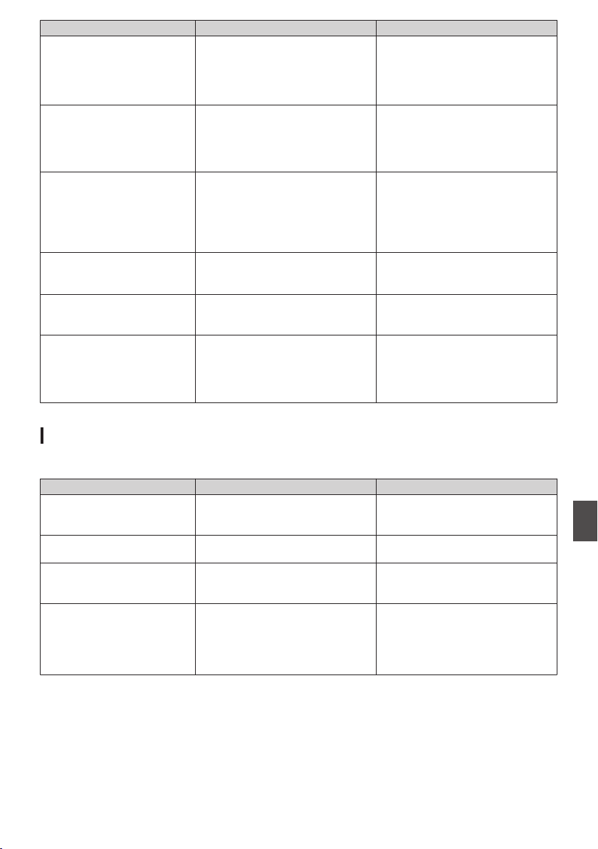
Error Message Status Action
Record Format Incorrect
0
The video format of the file for
Clip Review is different from the
current [WResolution],
[WFrame Rate], or [WBit Rate]
setting.
Set [WResolution], [WFrame Rate]
and [WBit Rate] correctly.
(A
P152 [ W Resolution ] )
(A P152 [ W Frame Rate ] )
(A P153 [ W Bit Rate ] )
Media Full
0
[REC] button is pressed when
the media in use has no
remaining space.
0
Remaining space ran out during
recording.
Replace the recording media with a
new one.
No Clips No viewable clips are found on the
card for Clip Review.
Insert an SD card that contains clips
that can be reviewed.
(A P
47 [SD Card] )
(
A P84 [Viewing Recorded
Videos Immediately (Clip
Review)] )
No Media When the [REC] button is pressed
while a recording media is not
inserted.
Insert a recording media.
(A P
47 [SD Card] )
No Media No recording media is inserted while
in Media mode or when the
thumbnail screen is displayed.
Insert a recording media.
(A P47 [SD Card] )
No Clips No clips are found in the inserted
recording media while in Media
mode
or when the thumbnail screen
is displayed.
Insert a recording media that
contains playable clips.
(A P47 [SD Card] )
(A P95 [Playing Recorded
Clips] )
List of FTP Transfer Errors
If the upload of a recorded clip or download of the metadata setup file (XML format) is not successfully
completed, the following errors are displayed.
Error message Status Action
Timeout. Transfer was discontinued due to
timeout caused by network
transmission or server failure.
0
Execute again.
0
Use a different server.
Media Was Removed. Recording media is removed while
FTP transfer is in progress.
Insert the recording media and
execute FTP transfer again.
Adapter Was Removed. The USB network device is
removed while FTP transfer is in
progress.
Connect the USB network device.
Cannot Connect to Server. Unable to connect to the FTP server. Adjust the Server and Port settings
for [Metadata Server] or [Clip
Server].
(A P
139 [ Metadata Server ] )
(A P146 [ Clip Server ] )
Error Messages and Actions
219
Others

Error message Status Action
Access Denied. Access is denied. Adjust the Server and Port settings
for [Metadata Server
] or [Clip
Server].
(A P139 [ Metadata Server ] )
(A P146 [ Clip Server ] )
Invalid Username or
Password.
Authentication for login to the FTP
server failed.
Adjust the Username and Password
settings for [Metadata Server] or
[Clip Server].
(A P139 [ Metadata Server ] )
(A P146 [ Clip Server ] )
Invalid Path Was Requested. The path specified for the FTP
server is incorrect.
Adjust the [Clip Server] and [Dir.
Path] settings for [Metadata
Server] or [File Path].
(A P139 [ Metadata Server ] )
(A P146 [ Clip Server ] )
Server Error. There was an unintended operation
of the FTP server.
Execute again.
Use a different server.
Invalid Request. A bad request is executed for the
FTP server.
Execute again.
Invalid Data Size. Invalid data size, such as a planning
metadata size that exceeds 4 KB.
Adjust the planning metadata saved
in the [Metadata Server
]
.
(A P195 [ Planning Metadata ] )
Invalid Data Format. The XML format of the planning
metadata is invalid.
Adjust the planning metadata saved
in the [Metadata Server].
(A P195 [ Planning Metadata ] )
Transfer Error. Transfer failed due to
communication failure.
Execute again.
Invalid URL. The path was deemed invalid by the
FTP server.
Adjust the Server and Port settings
for
[Metadata Server] or [Clip
Server].
(A P139 [ Metadata Server ] )
(A P146 [ Clip Server ] )
Media Access Error. Reading/writing of the recording
media failed while FTP transfer is in
progress.
Use a different recording media.
Internal Error. An internal error has occurred while
FTP transfer is in progress.
Adjust the settings and execute
again.
Other Error. An unknown error or other errors
have occurred while FTP transfer is
in progress.
Adjust the settings and execute
again.
Media Read Error. Reading of the recording media
failed while FTP transfer is in
progress.
Use a different recording media.
220
Error Messages and Actions
Others

List of Live Streaming Error Displays
The following error messages are displayed when the live streaming setting is incorrect, or when the
connection is lost during live streaming.
Error message Status Action
Invalid Address
0
The IP address format is
incorrect.
0
The domain name cannot be
converted into the IP address.
0
Enter
the
IP address, host name
or URL of the destination
correctly.
(A P212 [Setting Distribution] )
Multicast Is Not Supported An IP multicast address was set. Use an IP address that is not a
multicast address.
Cannot Connect to Receiver Establishment of connection with
TCP failed.
0
Ensure that the recipient’s
device is set to TCP.
0
Set Type to
“MPEG2-TS/UDP”.
(A P212 [Setting Distribution] )
TCP Disconnected TCP connection is lost. Check to ensure that there is no
abnormality in the decoder, or
network connection device and
cables,
followed
by establishing the
connection again.
Not Enough Bandwidth
0
The communication bandwidth
is narrower than the average bit
rate.
0
The network bandwidth is
insufficient, and packets are
discarded.
0
Lower the resolution/picture
quality of the video to be
distributed.
0
Consider switching to the use of
a stable network, such as wired
LAN.
Connection Timeout Timeout for connection via ZIXI. Set [Destination Address] and
[
Destination Port] correctly.
(A P212 [Setting Distribution] )
Authorization Failed Authentication of connection via
ZIXI failed.
Set [Stream ID] and [Password]
correctly.
(A P212 [Setting Distribution] )
Connection Error Connection via “ZIXI” or “RTMP”
failed.
0
Check whether a different
camera with an identical stream
ID is connected.
0
Set [Destination URL] and
[Stream Key] correctly.
(A P142
[ Destination URL ] )
(A P142 [ Stream Key ] )
Disconnected “ZIXI” or “RTMP” connection is lost. Check whether there is abnormality
with
the
network connection device,
cables, etc., and try to re-establish
the connection.
Error Messages and Actions
221
Others

Blinking of the Tally Lamp
The tally lamp starts blinking when the remaining space on the recording media is running out during
recording or when the battery power is running low.
Blinking Mode Remaining Battery Power/SD Card Space
Blinks slowly
(once every second)
0
Battery power is low
0
Remaining recording time on recording media is less than 3 minutes
(during recording)
0
When a malfunction occurred during live streaming
Blinks quickly
(2 times per second)
0
Remaining battery power is almost zero
0
Remaining
recording time on recording media has reached 0 minutes
(during recording)
0
Error on the camera recorder
Warning Tone
0
Warning tone is output from the speaker and [PHONE] terminal when the battery level is low.
Warning tone is also output when an error occurs in the camera recorder.
Memo :
0
Whether the sound is to be muted or output when it is at the minimum level can be configured in [Min.
ALARM Level].
(A P
137 [ Min. ALARM Level ] )
222
Error Messages and Actions
Others

Troubleshooting
Symptom Action
Power does not turn on.
0
Is the AC adapter properly connected?
0
Is the battery charged?
0
Is the power turned on immediately after it is turned off?
Make sure to wait for an interval of at least 5 seconds before turning
on the power again.
Unable to start recording.
0
Is the write-protect switch of the SD card turned on?
Make sure that the write-protect switch is turned off.
(A P48
[Write-Protect Switch on the SD Card] )
0
Is the camera recorder set to the Camera mode?
Use the [CAM/MEDIA] selection button to switch to the Camera mode.
(A P20 [Operation Modes] )
0
Is the SD card inserted compatible with the recording format?
(A P56 [Selecting a Video Format] )
(A P155 [ 4GB File Spanning(SDXC) ] )
Camera image is not output on
the LCD monitor and
viewfinder screen.
0
Is the camera recorder set to the Camera mode?
Use
the [CAM/MEDIA] selection button to switch to the Camera mode.
(A P20 [Operation Modes] )
Camera image is not output on
the LCD monitor.
0
Is the LCD backlight set to “Off”?
Press the
[B.LIGHT]
button to switch the mode.
(A P42 [Adjusting the LCD Monitor] )
Camera image is not output on
the viewfinder screen.
0
Is the CONTRAST knob on the viewfinder set to the minimum?
Adjust the [CONTRAST
] knob on the viewfinder.
(A P42 [Adjusting the Viewfinder] )
Playback does not start after
selecting a clip thumbnail and
pressing the [STATUS/SET
]
button (
R).
0
Is the selected clip a playable clip?
Playback is not possible if the clip has a different video format setting.
Images on the LCD monitor
and viewfinder screen appear
dark or blurred.
0
Readjust the brightness of the LCD monitor and viewfinder.
0
Is the [ND FILTER] switch set to “1/64”?
0
Is the iris closed?
0
Is the shutter speed setting too high?
0
Is the peaking level too low?
For the LCD monitor, adjust the outline with [LCD/VF] B [LCD
Peaking].
For the viewfinder, adjust the outline with the [PEAKING] knob on the
viewfinder. u v
(A P
42 [Adjusting the LCD Monitor] )
(A P42 [Adjusting the Viewfinder] )
Troubleshooting
223
Others

Symptom Action
The [CH-1/CH-2] recording
level adjustment knob does
not work.
0
Is
the [AUDIO SELECT CH1/2]-[MANUAL/AUTO] selection switch set
to “AUTO”?
0
Is Full Auto enabled?
Is
[Camera Function] B [Full Auto] B [Audio] set to “Auto” in Full Auto
mode?
(A P115 [Full Auto Item] )
[CH-3/CH-4] audio is not
recorded.
0
Is the number of recording channels set to
“4ch
”?
Set [System] B [Record Set] B [WAudio]/[YAudio] to “4ch”.
(A P153
[ W Audio ] )
Microphone audio cannot be
heard
through the headphone.
0
Is the audio setting configured to “IFB/RET Only”?
Set [A/V Set] B [Audio Set] B [IFB/RET Monitor] to “Off”.
(A P138
[ IFB/RET Monitor... 0 ] )
SD card cannot be initialized
(formatted).
0
Is the write-protect switch of the SD card turned on?
Make sure that the write-protect switch is turned off.
(A P48 [Write-Protect Switch on the SD Card] )
Battery alarm appears even
after loading a charged
battery.
0
Is the battery too old?
The time code and user’s bit
are not displayed.
0
Even in Camera mode or Media mode, the time code and user’s bit
may not be displayed depending to the type of display.
0
Is
[LCD/VF] B [Display On/Off] B [TC/UB] set to “Off”? To display the
date and time, set it to “On”.
(A P
130 [Display On/Off Item] )
The time is not displayed.
0
The
time is only displayed on the display screen in the Camera mode
(during shooting).
(A P161 [Display Screen in Camera Mode] )
0
Is [System] B [Record Set] B [Time Stamp] set to “On”? To display
the date and time, set it to “Off”.
(A P
156 [ Time Stamp ] )
The actual recording time is
shorter than the estimated
time.
0
The recordable time may be shorter depending on the shooting
conditions or the subject.
The two camera recorders are
not synchronized even though
the time codes have been
synchronized. (Z on the Slave
device is not displayed.)
0
Is the
[TC GEN] switch set to “F-RUN”?
(A P78 [Synchronizing the Time Code with an External Time Code
Generator] )
0
Set [System] B [Record Set] B [Record Format] B [WFrame Rate]
such that the two camera recorders have the same frame rate.
(A P152 [ W Frame Rate ] )
Cannot connect to wireless
LAN.
0
Check the mode of connection and method of setting (
[SSID] and
[Passphrase] in cases other than WPS).
(
A
P187 [Connecting to Network via [HOST] Terminal (USB) 0] )
(A P188 [Connecting to Network via Built-in Wireless LAN u v
0] )
0
Even if the Passphrase is wrong, “Completed the Setup Wizard.
Please Input the Passphrase into Your Device.” may appear at the
browser setting depending on the type of encryption.
Adjust [Passphrase] again.
0
Set [Network] B [Connection Setup] B [Default Gateway
] to a value
other than “LAN”.
(A P
140 [ Default Gateway ] )
224
Troubleshooting
Others

Symptom Action
The View Remote screen turns
black.
The screen flickers.
The screen freezes.
Cannot perform remote
operation.
0
The network path is congested.
Wait a while before refreshing (reloading) the web browser.
0
Clear the cache in your Web browser.
The clips cannot be uploaded
to the FTP server.
0
Adjust the [Clip Server
] settings.
(A P146 [ Clip Server ] )
0
If a file size limit is set in the FTP server, set the size limit such that it
is larger than the maximum size of the recorded clip.
0
Take necessary action as described in “[List of FTP Transfer Errors]
(A P 219)”.
The wireless LAN is
disconnected.
0
The wireless LAN may be disconnected depending on the
environment. Change the usage environment.
0
Connect via wired LAN.
(A P
186 [Connecting to Network via [LAN] Terminal 0
] )
The images and audio sound
during live streaming are
choppy.
0
Depending on the connection method to the network and connection
environment, streaming may not be possible with the encoding bit rate
specified. Please reduce the encoding bit rate.
GPS signal cannot be
received. u v
0
Signal reception from GPS satellites may be affected by buildings or
trees.
Perform
positioning
preferably at an unobstructed location with a clear
view.
0
Radio wave reception may be affected by weather conditions such as
on a cloudy or rainy day.
The position is not accurate.
u v
0
The
precision
error may be up to hundreds of meters if the GPS signal
is weak or reflected off surrounding buildings.
Troubleshooting
225
Others
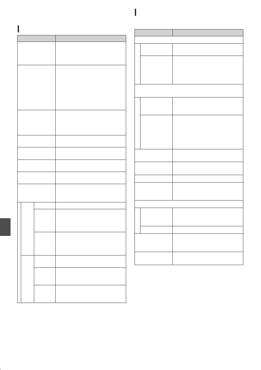
Specifications
General
Item Description
Power
When using an external power source:
DC 11.0 V to 17.0 V
When using a battery:
DC 14.4 V (Anton/Bauer, IDX)
Power
consumption
Approx. 38 W
(during single recording at
factory default settings while
using the viewfinder)
Approx. 33 W
(When using only the camera
body during single recording at
factory default settings)
Mass u : Approx. 5.1 kg (*1)
v : Approx. 5.2 kg (*1)
w : Approx. 4.3 kg (*2)
x : Approx. 4.4 kg (*2)
Allowable operating
temperature
0 ℃ to 40 ℃ (32 °F to 104 °F)
Allowable operating
humidity
30 %RH to 80 %RH
Allowable storage
temperature
-20 ℃ to 50 ℃ (-4 °F to 122 °F)
Drip-proof
performance
Equivalent to IPX2
Built-in wireless
LAN
u v
IEEE802.11a/b/g/n/ac
(2.4 GHz/5 GHz band)
Encryption method: WPA2
u
2.4 GHz Ch1, 2, 3, 4, 5, 6, 7, 8, 9, 10, 11
5 GHz
USA
Ch36, 40, 44, 48, 52, 56, 60, 64,
100, 104, 108, 112, 116, 120,
124, 128, 132, 136, 140, 149,
153, 157, 161, 165
5 GHz
CANADA
Ch36, 40, 44, 48, 52, 56, 60, 64,
100, 104, 108, 112, 116, 132,
136, 140, 149, 153, 157, 161,
165
v
2.4 GHz Ch1, 2, 3, 4, 5, 6, 7, 8, 9, 10, 11,
12, 13
5 GHz
Outside
Russia
Ch36, 40, 44, 48, 52, 56, 60, 64,
100, 104, 108, 112, 116, 120,
124, 128, 132, 136, 140
5 GHz
Russia
Ch36, 40, 44, 48, 52, 56, 60, 64,
132, 136, 140, 149, 153, 157,
161, 165
*1 Camera body and Viewfinder
*2 Camera body only
Terminal Section
Video/Audio
Item Description
[HD/SD SDI IN] terminal
3G-SDI,
HD-SDI
Compliant with SMPTE ST424,
Compliant with SMPTE ST292
3G-SDI,
HD-SDI
Embedded
audio
standard
Compliant with SMPTE ST299,
Compliant with SMPTE ST299
[HD/SD SDI OUT 1/2] terminal (480i or 576i: Downconverted
720p/1080i/1080p: embedded audio), BNC (unbalanced)
3G-SDI,
HD-SDI,
SD-SDI
Compliant with SMPTE ST424,
Compliant with SMPTE ST292,
Compliant with SMPTE ST259
3G-SDI,
HD-SDI,
SD-SDI
Embedded
audio
standard
Compliant with SMPTE ST299,
Compliant with SMPTE ST299,
Compliant with SMPTE ST272
[HDMI] output
terminal
Type A
[VIDEO OUT]
terminal (BNC)
Composite Video
1.0 V (p-p), 75 K (unbalanced)
[VF] terminal 26-pin
[MIC
IN] terminal
(XLR 5-pin)
-50 dBu, 4 kK, XLR (balanced),
+48 V output (phantom power
supply)
[AUDIO INPUT1/INPUT2] terminal (XLR 3-pin)
[MIC] -60 dBu, 4 kK, XLR (balanced),
+48 V output (phantom power
supply)
[LINE] +4 dBu, 10 kK, XLR (balanced)
[AUDIO OUT]
terminal
(XLR 5-pin)
0 dBu, 100 K, XLR (balanced)
[PHONE]
terminal
Φ3.5 mm stereo mini jack
226
Specifications
Others
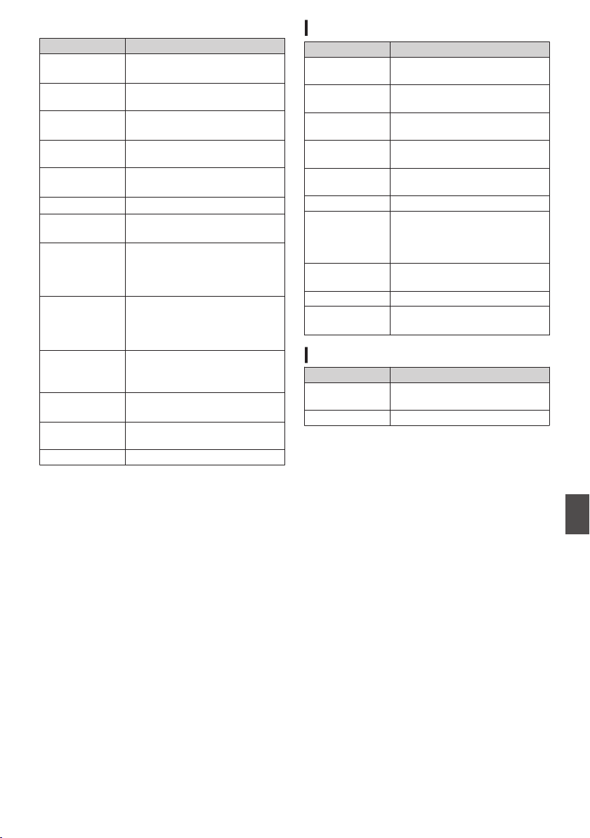
Others
Item Description
[LAN] terminal
(RJ-45)
100BASE-TX/1000BASE-T
[HOST] terminal USB-A type, network
connection function only
[REMOTE]
terminal
miniDin 6-pin
[TC IN] terminal 1.0 V(p-p) to 4.0 V(p-p) high
impedance
[TC OUT]
terminal
2.0 ± 1.0 V (p-p) low impedance
[LENS] terminal 12pin
[DC INPUT]
terminal
XLR 4-pin
[DC OUT]
terminal (rear)
4-pin, DC 11.0 V to 17.0 V, 1.8 A
u w x
4-pin, DC 11.0 V to 17.0 V, 1.5 A
v
[DC OUT] (LAN)
terminal
4-pin, DC 11.0 V to 17.0 V, 0.5 A
u w x
4-pin, DC 11.0 V to 17.0 V, 0.2 A
v
[LIGHT] terminal D-tap (DC 12 V, max. 50 W u
w x)
(DC 12 V, 2 A v)
[GENLOCK]
terminal
1.0 V (p-p), 75 K
Wireless audio
slot
UniSlot
2ch, -40 dBu (balanced)
Expansion slot For future expansion
Camera Section
Item Description
Image pickup
device
2/3-inch, 2.2 megapixels,
progressive CMOS x 3
Lens Mount 2/3-inch B4 Bayonet mount
system
Color separation
prism
F1.4, 3-color separation prism
Sensitivity F12, 2000 lx (standard value: 60
Hz)
Sync system External/Internal
Synchronization (Built-in SSG)
ND filter CLEAR, 1/4, 1/16, 1/64
Gain -6 dB, -3 dB, 0 dB, 3 dB, 6 dB, 9
dB,
12 dB, 15 dB, 18 dB, 21 dB,
24 dB, 27 dB, 30 dB, Lolux (24
dB, 30 dB, 36 dB,42 dB), AGC
Electronic
shutter
1/3 to 1/10000, EEI
LCD Monitor 3.5-inch LCD QHD (960 × 540)
Viewfinder u
v
3.26-inch OLED WVGA (854 ×
480)
Storage Section
Item Description
Supported
media
SDHC/SDXC
Slots x 2
Specifications
227
Others
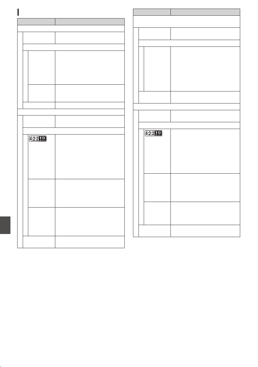
Video/Audio
Item Description
HD mode (MOV/MXF: MPEG-2)
Recording file
format
QuickTime File Format (MOV),
MXF File Format (MXF)0
Video
HQ mode MPEG-2 Long GOP VBR, 35
Mbps (Max) MP@HL,
1920x1080/59.94i, 29.97p, 50i,
25p
1440x1080/59.94i, 50i
1280x720/59.94p, 50p
SP mode MPEG-2 Long GOP CBR, 25
Mbps (Max) MP@H14
1440×1080/59.94i, 50i
Audio LPCM 2ch/4ch, 48 kHz/16 Bit
HD mode (MOV: H.264)
Recording file
format
QuickTime File Format
Video
XHQ Mode
MPEG-4 AVC/H.264, 70 Mbps
(Max) 0
1920×1080/59.94p, 50p
MPEG-4 AVC/H.264, 50 Mbps
(Max) 1920×1080/59.94p,
59.94i,29.97p, 23.98p2,
50p, 50i, 25p
1280×720/59.94p, 50p
XHQ Mode MPEG-4 AVC/H.264, 50 Mbps
(Max)
1920×1080/59.94p, 59.94i,
29.97p, 23.98p2, 50p, 50i,
25p
UHQ Mode MPEG-4 AVC/H.264, 35 Mbps
(Max)
1920×1080/59.94i, 29.97p,
23.98p2, 50i, 25p
1280×720/59.94p, 50p
Audio LPCM 2ch/4ch, 48 kHz/16 Bit,
24 Bit (422 10 bit only)
Item Description
HD mode (Exchange (U model) / MP4 (E model):
H.264) 0
Recording file
format
MP4 File Format
Video
LP mode MPEG-4 AVC/H.264, 12 Mbps
(Max)
1920x1080/59.94p (U model),
1920x1080/50p (E model),
MPEG-4 AVC/H.264, 8 Mbps
(Max)
1280x720/59.94p (U model)
1280x720/50p (E model)
Audio AAC 2ch, 48 kHz/16 Bit 128
kbps
HD mode (High-Speed) 2
Recording file
format
QuickTime File Format
Video
XHQ Mode
MPEG-4 AVC/H.264, 70 Mbps
(Max), 1920×1080
119.88/59.94p, 100/50p
MPEG-4 AVC/H.264, 50 Mbps
(Max), 1920×1080
119.88/59.94p, 100/50p,
119.88/29.97p, 100/25p,
119.88/23.98p
XHQ Mode MPEG-4 AVC/H.264, 50 Mbps
(Max), 1920×1080
119.88/59.94p, 100/50p,
119.88/29.97p, 100/25p,
119.88/23.98p
UHQ Mode MPEG-4 AVC/H.264, 35 Mbps
(Max), 1920×1080
119.88/29.97p, 100/25p,
119.88/23.98p
Audio LPCM 2ch, 48 kHz/16 Bit, 24 Bit
(422 10 bit only)
228
Specifications
Others
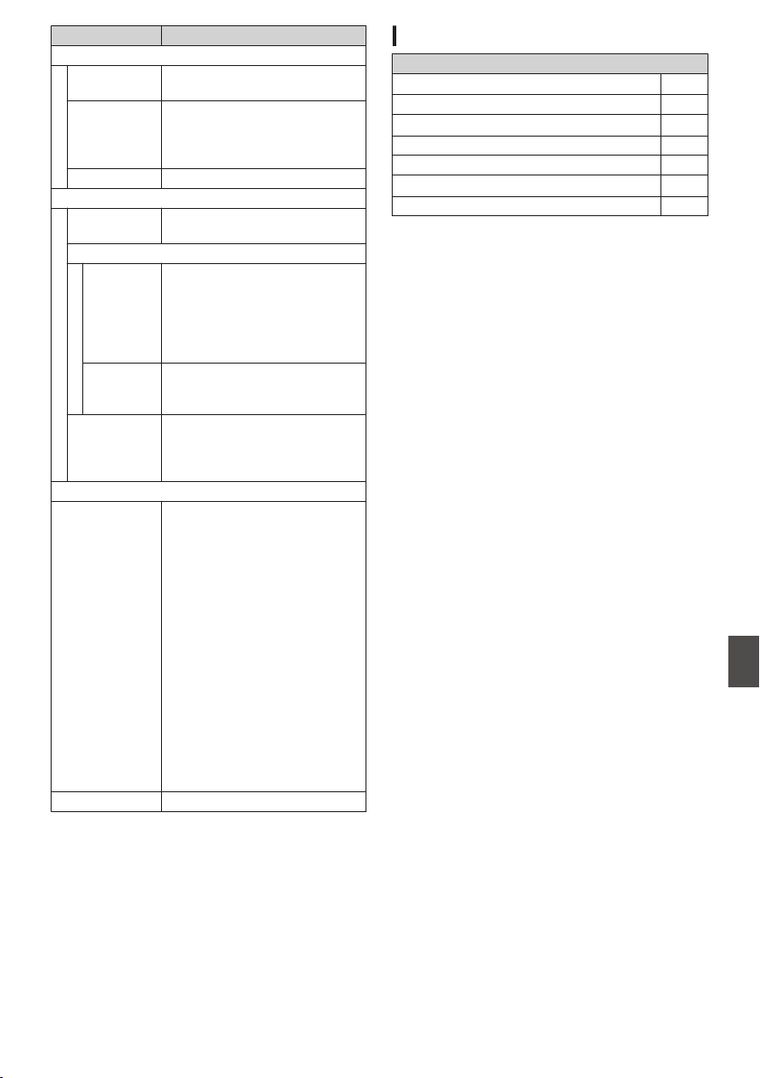
Item Description
SD mode (MOV: H.264) 2
Recording file
format
QuickTime File Format
Video MPEG-4 AVC/H.264, 8 Mbps
(Max)
720×480/59.94i (U model)
720×576/50i (E model)
Audio LPCM 2ch, 48 kHz/16bit
Web mode (MOV: H.264) 2
Recording file
format
QuickTime File Format
Video
HQ mode MPEG-4 AVC/H.264, 8 Mbps
(Max)
720x480/59.94i, 720x576/50i
MPEG-4 AVC/H.264, 3 Mbps
(Max)
960x540/29.97p, 25p, 23.98p
LP mode MPEG-4 AVC/H.264, 1.2 Mbps
(Max)
480x270/29.97p, 25p, 23.98p
Audio LPCM 2ch/4ch, 48 kHz/16 Bit
(720x480, 720x576)
μ-law 2ch/4ch, 16 kHz
(960x540, 480x270)
Streaming Mode
Video MPEG-4 AVC/H.264
1920x1080/59.94p, 50p
24/20/16/12/8 Mbps (Max)
1920x1080/59.94i, 50i, 29.97p,
25p
20/16/12/8/5/3 Mbps (Max)
1280x720/59.94p, 50p
20/16/12/8/5/3 Mbps (Max)
1280x720/29.97p, 25p
8/5/3/1.5 Mbps (Max)
2
720x480/59.94i (U model)
720x576/50i (E model)
8/5/3/1.5/0.8/0.3 Mbps (Max)
640x360/59.94p, 50p
3/1.5 Mbps (Max)
640x360/29.97p, 25p
3/1.5/0.8/0.3 Mbps (Max)
Audio AAC 2ch, 128/64 kbps
Accessories
Accessories
Warranty Card u w 1
INSTRUCTIONS (BASIC) 1
Electronic Viewfinder u v 1
Cold Shoe Unit 1
Screw (M2) 4
Wireless LAN Antenna u v 2
Core filter (large x 1, small x 1)v 2
* Eyepiece and body cap are attached to the
camera recorder.
Specifications
229
Others
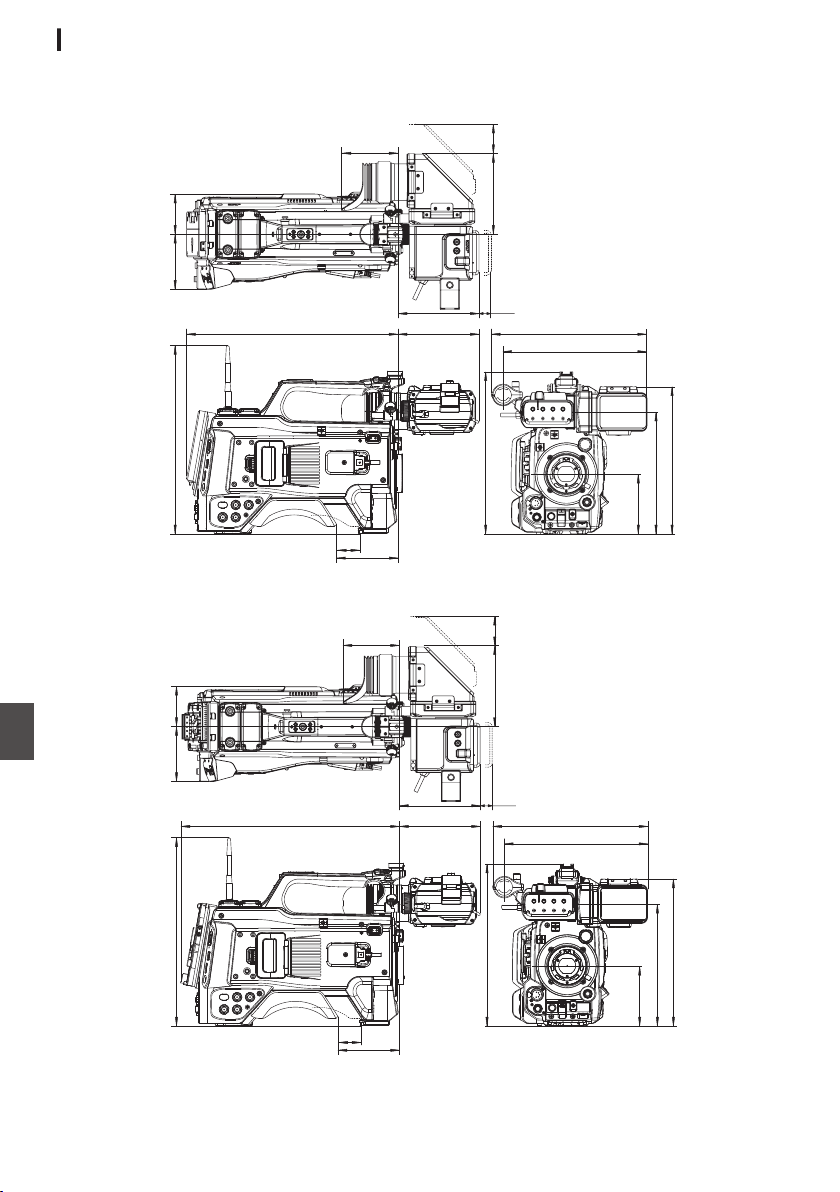
Dimensional Outline Drawing (Unit: mm)
Wireless LAN antenna and viewfinder are not included in GY-HC900STU and GY-HC900RCHE.
For U Model
.
104
40
137.5
(137.5)
96
20
(VF MOVE)
(S.PAD
MOVE)
(VF
MOVE)
265
244
359
319 69
137 50
93.5
251
276
207
102.4
For E Model
.
104
40
137.5
(137.5)
96
20
(VF MOVE)
(S.PAD
MOVE)
(VF
MOVE)
265
244
371
319 69
137 50
93.5
251
276
207
102.4
* The specifications and appearance of this product are subject to changes for further improvement
without prior notice.
230
Specifications
Others
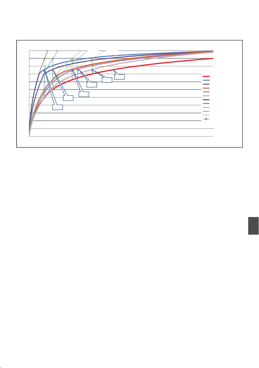
Appendix
Tone Mapping Characteristics for Converting HLG to ITU709 for LCD/VF
.
*1
*2
*3
*5
*6
*4
0
10
20
30
40
50
60
70
80
90
100
110
0 0.1 0.2 0.3 0.4 0.5 0.6 0.7 0.8 0.9 1
INPUT
OUTPUT (IRE)
hlg
50%white + KNEE
60%white +_KNEE
72.5%_white + knee
75%_white + knee
80%_white + knee
ITU709_50%
ITU709_60%
ITU709_72.5%
ITU709_75%
ITU709_80%
WHITE POINT
50%
60%
72.5%
75%
80%
50%
ITU709
60%
ITU709
72.5%
ITU709
75%
ITU709
80%
ITU709
*1 HLG
*2 White Level
80% converted
*3 White Level
75% converted
*4 White Level
72.5% converted
*5 White Level
60% converted
*6 White Level
50% converted
Appendix
231
Others

Index
A
AC adapter .......................................... 33, 34
Action
........................................................ 97
Aspect ratio ................................................ 57
B
Backup rec ................................................ 88
Battery ................................................. 17, 34
Brightness adjustment ............................... 59
C
Camera control function ........................... 202
Camera mode .............................. 21, 40, 161
Clip continuous rec .................................... 91
Clip cutter trig (splitting clips) ..................... 94
Clip name ............................................. 52, 96
Clip review ................................................. 84
Color bar .................................................. 172
Color matrix ............................................. 174
Connection settings file ............................ 207
Continuous operating time ......................... 34
D
Deleting clips ........................................... 100
Display screen ........................... 40, 161, 167
Dual rec ..................................................... 86
E
Electronic shutter ....................................... 62
Error message ................................... 66, 218
Expanded focus ......................................... 58
External monitor ....................................... 179
F
Favorites menu ........................................ 157
FAW (Full Auto White Balance) . 63, 110, 113
FEC Matrix ............................................... 215
File format .................................................. 55
Focus ......................................................... 58
Focus assist ............................................... 58
Formatting (initializing) SD cards ............... 50
Frame rec .................................................. 92
FTP Resume ............................................ 194
FTP server ................................. 98, 189, 191
G
Gain adjustment ........................................ 61
Genlock ................................................... 182
GPS ................................................... 83, 148
H
Headphone .............................................. 181
Histogram .......................................... 85, 127
I
Initial settings ............................................. 38
Interval rec ................................................. 93
Iris adjustment ........................................... 60
L
LCD monitor ............................. 17, 36, 40, 42
Live streaming ......................................... 210
M
Marker display ......................................... 172
Media mode ................................. 21, 40, 167
Menu ........................................ 105, 106, 108
Metadata .......................................... 189, 195
N
ND filter ...................................................... 22
Network ........................................... 139, 185
Network operating environment ............... 186
O
OK mark .................................................. 101
Operation lock ........................................... 53
P
Picture quality setting ................................. 69
Power .................................................. 36, 37
Pre rec ....................................................... 90
R
Recordable time ........................................ 47
Remote edit mode ............................... 21, 41
Resolution .................................................. 55
Restoring SD card ..................................... 51
Return Audio ............................................ 217
Return over IP .................................. 143, 216
Return Videos .......... 114, 135, 135, 184, 217
S
Safety zone display .................................. 172
SD/SDHC/SDXC card ......................... 18, 47
SDI ........................................................... 179
Selecting multiple clips ............................ 102
Series rec .................................................. 86
Setting the date/time .................................. 39
Setup file .................................................. 176
Shooting .................................................... 54
Software keyboard ................................... 107
Spot meter ................................................. 81
Status screen ..................................... 41, 170
Switching shutter speed ............................ 62
T
Tally lamp .......................................... 46, 222
Thumbnail (detailed screen) ...................... 97
Thumbnail (standard screen) ..................... 95
Thumbnail screen ...................................... 95
Time code ............................................ 73, 74
Time code generator ................................. 74
Time code playback ................................... 99
Trimming .................................................. 104
U
User button ................................................ 45
User’s bit .................................................... 73
V
Video format .............................................. 55
View remote ............................................. 202
Viewfinder ................................ 17, 36, 40, 42
232
Index
Others

W
Warning ............................................. 41, 222
Web browser ............................ 195, 199, 204
White balance adjustment ......................... 63
White paint ................................................. 66
Wired LAN ............................................... 186
Wireless LAN ............................. 32, 187, 188
Wizard .............................. 140, 186, 187, 188
Z
Zebra pattern ............................................. 80
Zoom ......................................................... 57
Index
233
Others

Software License
Agreement
The software embedded in the Product (hereinafter
the “Licensed Software”) provided by
JVC KENWOOD Corporation (hereinafter the
“Licensor”) is copyrighted to or sublicensable by the
Licensor, and this Agreement provides for the terms
and conditions which Users shall follow in order to
use the Licensed Software. The User shall use the
Licensed Software by agreeing with the terms of this
Software License Agreement. This Agreement shall
be deemed completed at the time the User
(hereinafter the “User”) initially used the Product in
which the “Licensed Software” is embedded.
The Licensed Software may include the software
which has been licensed to the Licensor directly or
indirectly from any third party. In such case, some
third parties require the Users to follow their
conditions for use separately from this Software
License Agreement. Such software shall not be
subject to this Agreement, and the Users are urged
to read the “[Important Notice concerning the
Software] (A P 235)” to be provided separately.
Article 1 General Provision
The Licensor shall grant to the User a non-exclusive
and non-transferable (other than the exceptional
case referred to in Article 3, Paragraph 1) licensed
to use the Licensed Software within the country of
the User (the country where the User bought the
Product (hereinafter the “Country”)).
Article 2 License
1. The license granted under this Agreement shall be
the right to use the Licensed Software in the Product.
2. The User shall not duplicate, copy, modify, add,
translate or otherwise alter, or lease the Licensed
Software and any related documents, whether in
whole or in part.
3. The use of the Licensed Software shall be limited
to personal purpose, and the Licensed Software
shall not be distributed, licensed or sub-licensed
whether it is for commercial purpose or not.
4. The User shall use the Licensed Software
according to the directions described in the
operation manual or help file, and is prohibited to use
or duplicate any data in a manner violating the
Copyright Law or any other laws and regulations by
applying whole or a part of the Licensed Software.
Article 3 Conditions for Grant of License
1. When the User transfers the Product, it may also
transfer the license to use the Licensed Software
embedded in the Product (including any related
materials, updates and upgrades) on condition that
no original, copies or related materials continue in
the possession of the User, and that the User shall
cause the transferee to comply with this Software
License Agreement.
2. The User shall not carry out reverse engineering,
disassembling, decompiling or any other code
analysis works in connection with the Licensed
Software.
Article 4 Right pertaining to the Licensed
Software
1. Any and all copyrights and other rights pertaining
to the Licensed Software and related documents
shall belong to the Licensor or the original holder of
the right who granted to the Licensor the license or
sublicense for the Licensed Software (hereinafter
the “Original Rightholder”), and the User shall not be
entitled to any right other than the license granted
hereunder, in respect of the Licensed Software and
any related documents.
2. The User shall, whenever the User uses the
Licensed Software, comply with any laws relating to
the copyright and other intellectual property rights.
Article 5 Indemnification of Licensor
1. Neither the Licensor nor the Original Rightholder
shall be liable for any damage incurred by the User
or any third party due to the exercise of the license
granted to the User under this Agreement, unless
otherwise restricted by law.
2. The Licensor will offer no guarantee for the
merchantability, convertibility and consistency with
certain objective of the Licensed Software.
Article 6 Liability to Third Party
If any dispute has arisen with any third party due to
an infringement upon a copyright, patent or any other
intellectual property right that was caused by the
User’s use of the Licensed Software, the User shall
settle such dispute at the User’s own cost and hold
the Licensor and the Original Rightholder harmless
from any inconvenience it may cause.
Article 7 Confidentiality
The User shall keep the confidentiality of such
portion of the Licensed Software, related documents
thereof or any other information to be granted under
this Agreement, as well as the conditions of this
Agreement as has not yet entered the public domain,
and shall not disclose or divulge the same to any third
party without approval of the Licensor.
Article 8 Termination
In case the User falls under any of the events
described in the following items, the Licensor may
immediately terminate this Agreement or claim that
the User compensates for the damage incurred by
the Licensor due to such event:
(1) when the User violated any provision of this
Agreement; or
(2) when a petition has been filed against the User
for an attachment, provisional attachment,
provisional disposition or any other compulsory
execution.
234
Software License Agreement
Others

Article 9 Destruction of the Licensed Software
If this Agreement is terminated pursuant to the
provision of Article 8, the User shall destroy the
Licensed Software, any related documents and
copies thereof within two (2) weeks from such date
of termination.
Article 10 Export Restriction
1. The User shall understand that the Licensed
Software shall be subject to the export restrictions
adopted by the country of User and any other
countries.
2. The User shall agree that the software will be
subject to any and all applicable international and
domestic laws including the export control regulation
of the country of User and any other countries, and
any restrictions concerning the end-users, the use
by end-users and importing countries to be provided
by the country of User and any other countries, and
any other governmental authorities.
3. If the User is an agency of the United States of
America (the “Government”), the User acknowledge
Licensor’s representation that the Licensed
Software is a “Commercial Item” as defined in
Federal Acquisition Regulation (FAR) part 2.101(g)
consisting unpublished “Commercial Computer
Software” as those items are used at FAR part
12.212 and is only license the User with the same
use right Licensor grants all commercial end users
pursuant to the terms of this Agreement.
Article 11 Miscellaneous
1. In the event any part of this Agreement is
invalidated by operation of law, the residual
provisions shall continue in force.
2. Matters not stipulated in this Agreement or any
ambiguity or question raised in the construction of
this Agreement shall be provided or settled upon
good-faith consultation between the Licensor and
the User.
3. The Licensor and the User hereby agree that this
Agreement is governed by the laws of Japan, and
any dispute arising from, and relating to the rights
and obligations under, this Agreement shall be
submitted to the exclusive jurisdiction of the Tokyo
District Court for its first instance.
Important Notice
concerning the Software
Software License Attached to the Product :
The Software embedded in the Product is composed
of several independent software components, and in
each of such individual components (hereinafter the
“Licensed Software”), a copyright of either
JVC KENWOOD Corporation (hereinafter “JKC”) or
a third party subsists.
The Product uses the software component
designated in the End-User License Agreement that
was executed between JKC and a third party
(hereinafter “EULA”).
The Licensed Software covers those corresponding
to free software, and, as a condition of distribution of
the software component in executable format which
is based on the license granted under the GNU
General Public License or Lesser General Public
License (hereinafter “GPL/LGPL”), it requires an
availability of the source code for the relevant
component. Please refer to the following URL
concerning the distribution of the source code;
https://www3.jvckenwood.com/english/
download/gpl/index.html
Please note that we are unable to answer any inquiry
relating to the contents, etc. of the source code. In
addition, the Licensed Software includes the
software developed or created independently by
JKC and there exists an ownership of JKC in such
software and any accompanying documents, which
is protected by the Copyright Law, any international
treaties and other applicable laws. As to matters
concerning the handling by JKC of the software
components, please refer to the “Software License
Agreement” attached hereto. Please note that any
software component licensed under “EULA” which
is not subject to “GPL/LGPL”, and those developed
or created independently by JKC shall not be subject
to the requirement for provision of the source code.
The software component distributed under “GPL/
LGPL” shall be licensed to users without charge,
and, therefore, no warranty is given for such software
component, either express or implied, within the
scope of the applicable laws and regulations. Unless
otherwise permitted by applicable laws and
regulations or agreed in written form, none of the
owners of the copyright or persons entitled to alter or
redistribute the software component under the said
license shall have any liability for any type of damage
or loss resulting from the use of or inability to use
such software component. For further details of the
conditions of use of such software component or
matters required to be complied with, please refer to
the relevant “GPL/LGPL”.
Users are urged to read the details for the relevant
license carefully before using the software
component covered by “GPL/LGPL” and embedded
in the Product. Since the terms and conditions of
individual licenses are provided by parties other than
JKC, the original English version will be displayed by
the Product.
A
Turn on the power.
B
Press the [MENU/THUMB] button.
C
Select [System]
B
[System Information]
B
[Open
Source License].
Software License Agreement
235
Others

.
GY-HC900CHU/GY-HC900CHE
GY-HC900STU/GY-HC900RCHE
HD MEMORY CARD CAMERA RECORDER
© 2019 JVC KENWOOD Corporation
B5A-2755-00