McIntosh Laboratory, Inc. 2 Chambers Street Binghamton, New York 13903-2699 Phone: 607-723-3512 www.mcintoshlabs.com
MC451
Dual Mono
Power Amplifier
Owner’s Manual
2
Introduction (continued)
The MC451 has 150 watts of vacuum tube power
to drive your loudspeaker’s mid ranges and tweeters.
With the MC451, the tubes will not be challenged
or overloaded by low-end reproduction because the
solid state section has 300 watts dedicated to driving
the woofers.
Fine tuning your system is made simple with the
built-in crossover. This allows you to match the
crossover point to your loudspeakers and maximize
the power available to each section. Alternatively,
section and bypass the crossover. This is perfect if
you have crossovers external to the MC451.
®
for clipping protection, Sentry Monitor™ for
over current protection, and ThermalTrak
1
output
transistors for stable bias and temperature control.
The output Autoformer™ provides the full 300W
of power regardless of loudspeaker impedance and
provides DC protection to the outputs.
®
for output tube protection and Sentry
Monitor™ for over current protection. The Unity
Coupled Output Transformer™ provides the full
150W of power regardless of loudspeaker imped
-
ance and provides DC protection to the outputs.
Copyright 2022 © by McIntosh Laboratory, Inc.
Table of Contents
Safety First �� �� �� �� �� �� �� �� �� �� �� �� �� �� �� 2
Introduction�� �� �� �� �� �� �� �� �� �� �� �� �� �� �� 2
Where to Put It� �� �� �� �� �� �� �� �� �� �� �� �� �� 3
Dimensions �� �� �� �� �� �� �� �� �� �� �� �� �� �� �� 3
Removal of Foam Insert Over Vacuum Tubes �� 4
Connector Information �� �� �� �� �� �� �� �� �� �� 5
Connecting a Loudspeaker � �� �� �� �� �� �� �� �� 5
Front Panel Displays and Knobs �� �� �� �� �� 6-7
Rear Panel Connections and Switches �� �� �� 8-9
Connection Diagram �� �� �� �� �� �� �� �� �� 10-11
Setting Up the Crossover� �� �� �� �� �� �� �� 12-13
Solid State Specifications �� �� �� �� �� �� �� �� ��14
Vacuum Tube Specifications �� �� �� �� �� �� �� ��14
General Specifications� �� �� �� �� �� �� �� �� �� ��14
Packing Instructions �� �� �� �� �� �� �� �� �� �� ��15
Packaging Parts List �� �� �� �� �� �� �� �� �� �� ��15
Thank You from All of Us at McIntosh
You have invested in a precision instrument that
will provide you with many years of enjoyment.
with the features and instructions to get the maxi-
mum performance from your MC451.
If you need further technical assistance, please
contact your dealer who may be more familiar with
your particular setup including other brands. You
can also contact McIntosh with additional questions
or in the unlikely event of needing service.
McIntosh Laboratory, Inc�
2 Chambers Street
Binghamton, New York 13903
Technical Assistance (607) 723-3512
Fax (607) 724-0549
Customer Service (607) 723-3515
Fax (607) 723-1917
Email support@mcintoshlabs.com
Website www.mcintoshlabs.com
Please Take A Moment
For future reference, you can write down your
serial number and purchase information here. We
can identify your purchase from this information
if the occasion should arise:
Serial Number: __________________________
Purchase Date: ___________________________
Dealer Name: ___________________________
Introduction
is an all-in-one solution for bi-amping
loudspeakers. Utilizing our Hybrid
Drive™ technology, it captures
the harmonic beauty of vacuum tubes for a
loudspeaker’s mid and high ranges while still having
an
abundance of power dedicated to the low end. The
its optimized combination of a vacuum tube and a
Safety First
separate document called Important Additional
Operation Information Guide.
1
ThermalTrak
™
is a trademark of Semiconductor
Components Industries, LLC
3
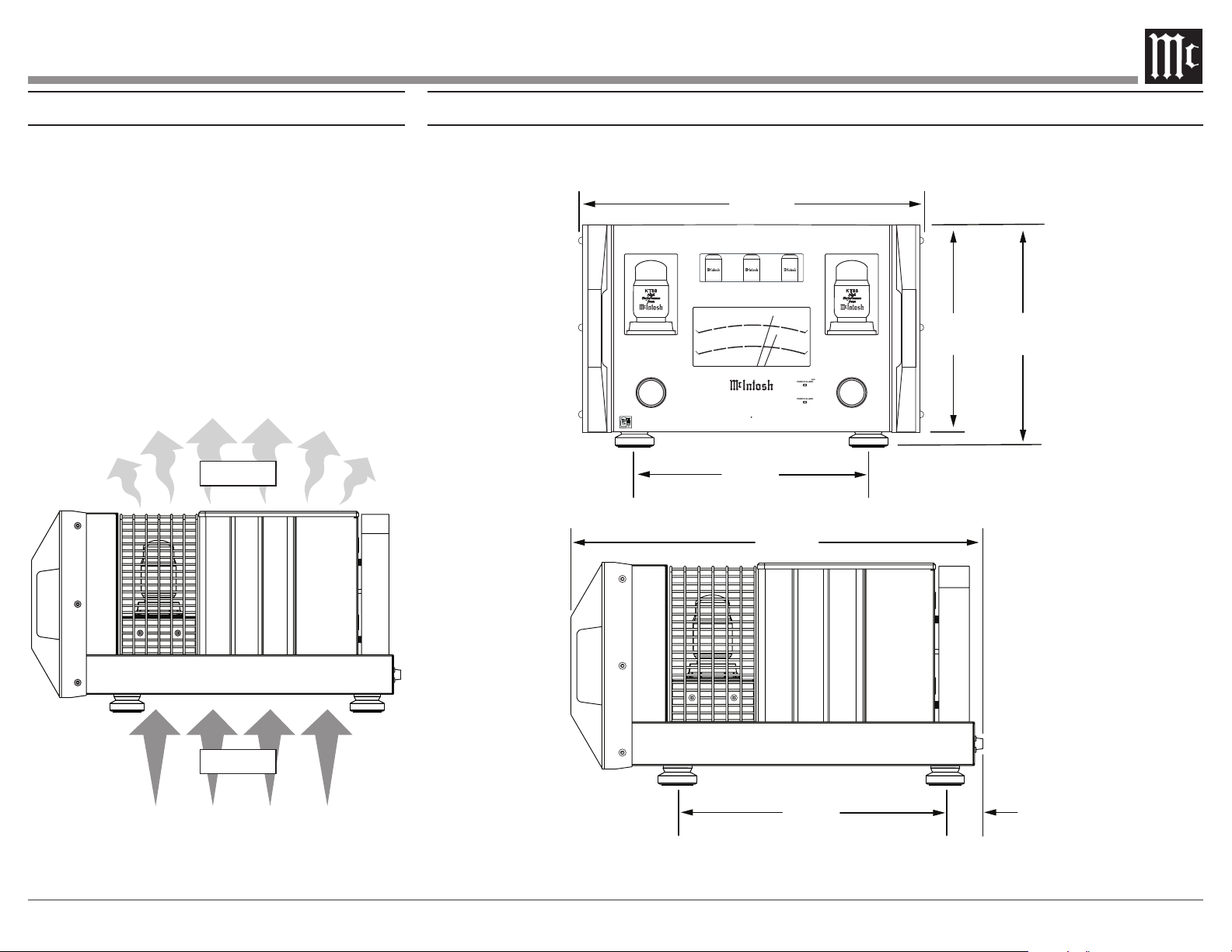
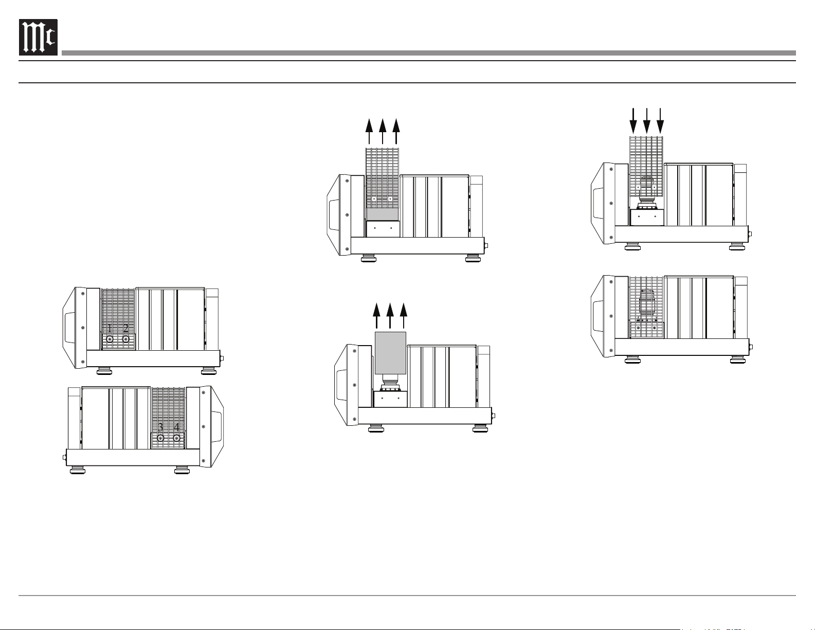
Where to Put It
The MC451 is very heavy� When moving the
unit, have enough help to lift the MC451. This will
ensure the safety of both you and the MC451.
The MC451 should be installed upright on the
is important and will aid in a long trouble-free life
allowing at least 19 inches (48.3cm) above the unit
and 6 inches (15.2cm) for the front, rear and sides.
Do not remove the feet
beneath the MC451. There must be openings for
cool air to enter (below) and warm air to escape
(above) the MC451.
Cool Air
Warm Air
Dimensions
The following dimensions can assist in determining the best location for your MC451.
17
⁷/8
45.4 cm
2
10
⁷/8
27.6 cm
11
¹³/16
30 cm
12
¹/4
31.1 cm
¹⁵ 16
WATTS
HOLD
LIGH TS
OFF
MET ER
REMO TE
OFF
ON
POW ER
M C 4 5 1
D U A L M O N O
P O W E R A M P L I F I E R
WARMUP
TEMP
K T8 8 K T8 8
30
30 0
3.0
.30
P O W E R O UT PU T
- 50
- 30
DE CI BEL S
- 40
-20
-1 0
0
600
30
m
3.0
m
15
150
1.5
.15
- 50
- 30
- 40
-20
-1 0
0
300
15
m
1.5
m
WAT TS
USA
12AT7
USA
12AT7
USA
12AX7A
⁷ 8
21 ¹/2
54.6 cm
14”
35.6 cm
⁷ 8
16
4 1 ¹⁵/16
4.9 cm
WATTS
HOLD
LIGH TS
OFF
MET ER
REMO TE
OFF
ON
POW ER
K T8 8 KT 88
USA
12AT7
USA
12AT7
USA
12AX7A
4
To prevent damage to the tubes during shipping,
there is a foam insert surrounding the tubes of the
The foam insert must be removed from the
MC451 before connecting AC Power�
Failure to do so is a re hazard, and can result
in damage to the MC451 and the surrounding
environment�
To remove the foam insert, it is necessary to
temporarily remove the tube cover. To remove the
tube cover:
1. Use a #2 phillips head screw driver to remove
the four screws (two on each side) that hold the
tube cover.
2.
the MC451.
3.
tubes.
Removal of Foam Insert Over Vacuum Tubes
4. Replace the tube cover.
5. Replace the four screws to secure the cover.
6. Save the protective foam for possible future use.
5
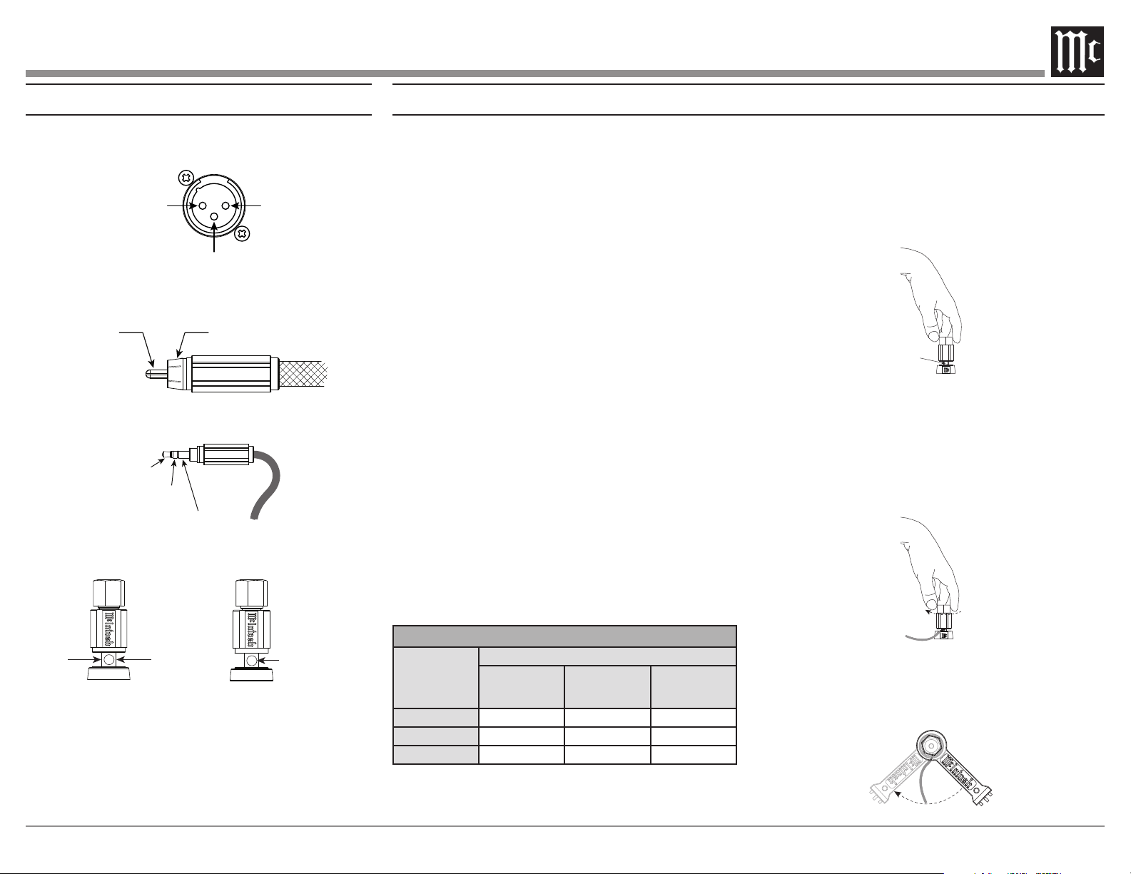
Connector Information
XLR Connectors
When connecting loudspeaker cables to the
MC451 output terminals follow the steps below:
1� Make sure AC power is disconnected�
2. Rotate the top of the output terminal counter
-
clockwise until an opening appears.
Opening
Loudspeaker Connections
The MC451 is designed for two separate connec-
tions to a single loudspeaker. The solid state
the low frequency terminals of your loudspeaker.
the mid/high terminals of your loudspeaker. Any
jumpers between the low and mid/high terminals
on the loudspeaker must be removed� Refer to the
Connection Diagram on pages 10-11 for additional
information.
Loudspeaker Impedance
of your loudspeaker, determine the best impedance
to use for each connection. It is a safe bet to use
the lower impedance output terminals for a speaker
whose impedance falls between two choices.
Loudspeaker Cables
When connecting loudspeakers to the MC451 it is
very important to use cables of adequate size. The
The smaller the gauge number, the larger the wire
size.
Loudspeaker Cable Wire Gauge Guide
Loudspeaker
Impedance
Cable Distance
25 feet
(7.62 meters)
or less
50 feet
(15.24 meters)
or less
100 feet
(30.48 meters)
or less
2 ohms 12AWG 10AWG 8AWG
4 ohms 14AWG 12AWG 10AWG
8 ohms 16AWG 14AWG 12AWG
Connecting a Loudspeaker
3. Insert the loudspeaker cable into the output
terminal.
Proper polarity must be
maintained for all connections� (+/-)
4. Rotate the top of the output terminal clock-
5.
output terminal and rotate it one quarter of a
turn (90°).
Do not over tighten�
Meter/Tube
Illumination
Control
Power
Control
Ground
Signal Ground
RCA Connectors
Power Control Connectors
Output Terminals
(+) Signal Ground
(-) Signal
2
1
3
3/10 in
7.6 mm
/ in
4.4 mm
Ø

6
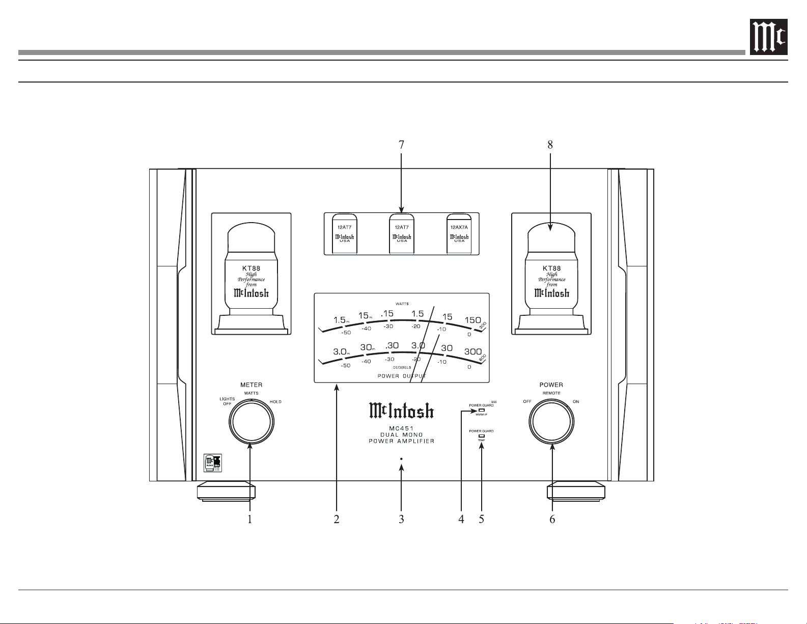
1� METER Control Knob
output.
• WATTS - the meter responds to all output.
• HOLD - the dual meter needles will hold the
highest peak until a higher peak is reached.
If no higher peak is reached, the needles will
lower their levels at a rate of approximately
6dB per minute.
Note: When in the WATTS or HOLD position, the meter
and tube lights will be powered On or Off by a
preamplifier or A/V control center connected by a
power control cable if that unit has power control
capabilities.
2� Dual Power Output Meter
Shows both the vacuum tube and solid state
scale is displayed on the top and indicated by
the longer needle. The solid state scale is on the
bottom and indicated by the shorter needle.
3� Standby LED
Indicates that the MC451 is connected to AC
power and ready to be turned on via the front
panel knob or rear panel power control.
In the unlikely event of a fault in the MC451’s
control knob to OFF, wait one minute, then turn
-
ues to occur, the MC451 should be serviced.
4� POWER GUARD SGS
®
(Screen Grid Sensor)
LED
vacuum tube warm up.
current in the KT88 output vacuum tubes. If the
attenuates the input signal in real time to keep
the vacuum tubes operating at safe levels.
5� POWER GUARD
®
LED
over temperature.
time, then makes unobtrusive adjustments to
prevent distortion and potential speaker damage.
6� POWER Control Knob
regardless of any power control connection.
• REMOTE- the MC451 can be powered on
center connected by a power control cable.
• ON- the MC451 will be powered on
regardless of any power control connection.
7� Vacuum Tube Input Stage
Sentry Monitor™ provides protection by
monitoring current in the output transformer.
In the event of a large impedance mismatch,
a short circuit at the output terminals or tube
failure, Sentry Monitor will activate to prevent
potentially destructive levels of current from
When Sentry Monitor is activated, the MC451
To reset the Sentry Monitor protection circuitry,
to ON. If Sentry Monitor continues to engage,
8� Vacuum Tube Output Stage
Note: Because of the high voltage involved with all vacuum
tubes, they should only be replaced by an authorized
McIntosh dealer or service agency.
Front Panel Displays and Knobs
7
Front Panel Displays and Knobs

8
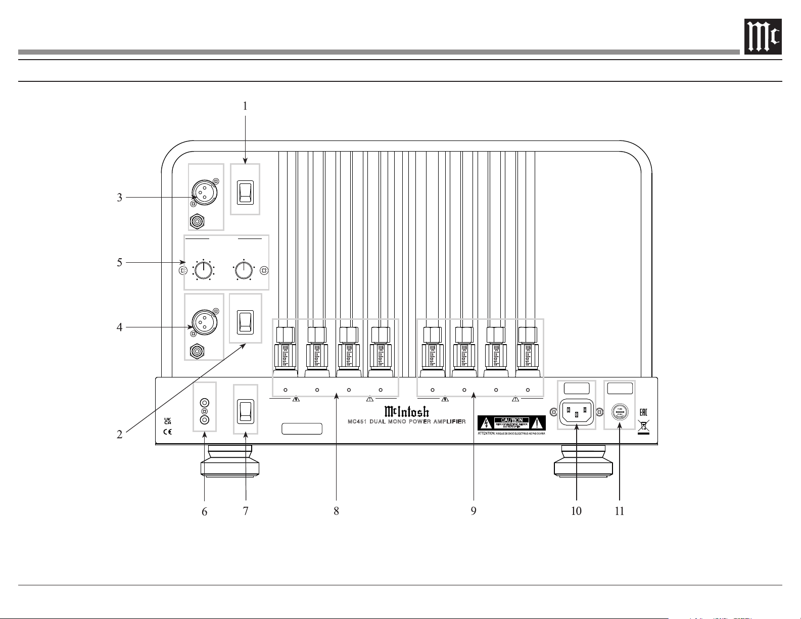
Rear Panel Connections and Switches
1� Input Mode
To select the BALANCED or UNBALANCED
to toggle between these two options. Each
cable or a male unbalanced RCA cable. All
inputs must use the same type of connection
(BALANCED or UNBALANCED).
Refer to
page 5, Connector Information.
2� Amplier Mode
MONO is the common choice for most
applications of the MC451. The signal from
frequency range tailored by the crossover to
match the attached loudspeaker.
can be useful for situations where
also be used for feeding full-range signals to
two separate loudspeakers from a single MC451.
Note: If you need to switch the INPUT or AMPLIFIER
MODE, it is best to do so when the MC451 is
powered off to avoid any unpleasant noise from the
loudspeakers.
3� Vacuum Tube Input
With the switch set to
MONO, the input is disabled.
With the switch set to
, this input sends a full range input
4� Mono / Solid State Input
With the switch set to
MONO, the input signal is sent to the internal
crossover. The crossover then sends signals to
settings.
With the switch set to
, this input sends a full range input
5� Crossover
Refer to page 12, Setting Up the Crossover for
additional information.
6� Power Control
receive control signals when connected to other
McIntosh products. In this way, powering on
same for multiple units.
signal from +5 to +12 volts. Meter and tube
lights can be controlled as well.
volt signal with a total current up to 25 mA.
mini phone plug. Refer to page 5, Connector
Information.
7� Auto O Function
The MC451 incorporates power saving circuitry
to automatically activate the power saving
approximately 30 minutes of no audio signal in
set to ENABLED.
If the AUTO OFF switch is set to DISABLED,
the MC451 will remain on regardless of the
presence of any audio signal.
When there is a power control connection
component, the AUTO OFF function is disabled
regardless of switch position.
8� Vacuum Tube Outputs
Refer to page 5, Connecting a Loudspeaker
for additional information.
9� Solid State Outputs
Refer to page 5, Connecting a Loudspeaker
for additional information.
10� AC Input
Connect the MC451 power cord to a live AC
outlet. Refer to the rear panel for voltage and
current requirements.
11� Fuse
Under normal operating conditions the fuse
should not need to be replaced. If required, refer
to the rear panel for proper fuse type.
9
SERIAL
NUMBER
CAUTION
RISK OF ELECTRIC SHOCK
DO NOT OPEN
MC 4 51 D U AL MO NO PO WER A MPL I FI E R
McINTOSH LABORATORY, INC., BINGHAMTON, NY
HANDCRAFTED IN USA WITH US AND IMPORTED PARTS
+++
-
8Ω 4Ω 2Ω COM
-
COM
++
4Ω 8Ω
+
2Ω
SOLID STATE (300W) OUTPUTS
CLASS 2 WIRING
VACUUM TUBE (150W) OUTPUTS
CLASS 2 WIRING
POWER
CONTROL
OUT
IN
AUTO OFF
ENABLED
DISABLED
CROSSOVER
(MONO MODE)
VACUUM TUBE
INPUT
INPUT MODE
BALANCED
UNBALANCEDBAL
UNBAL
MONO SOLID STATE/
INPUT
AMPLIFIER MODE
MONO
SEPARATEBAL
UNBAL
300
250 400
550
180
130 800
1k100
CROSSOVER POINT
Hz
+1.2
-3
+3-6
0
VACUUM TUBE LEVEL
dB
Rear Panel Connections and Switches
10
SERIAL
NUMBER
CAUTION
RISK OF ELECTRIC SHOCK
DO NOT OPEN
MC 4 5 1 DUA L M O NO PO W E R AMP L I FIE R
McINTOSH LABORATORY, INC., BINGHAMTON, NY
HANDCRAFTED IN USA WITH US AND IMPORTED PARTS
+++
-
8Ω 4Ω 2Ω COM
-
COM
++
4Ω 8Ω
+
2Ω
SOLID STATE (300W) OUTPUTS
CLASS 2 WIRING
VACUUM TUBE (150W) OUTPUTS
CLASS 2 WIRING
POWER
CONTROL
OUT
IN
AUTO OFF
ENABLED
DISABLED
CROSSOVER
(MONO MODE)
VACUUM TUBE
INPUT
INPUT MODE
BALANCED
UNBALANCEDBAL
UNBAL
MONO SOLID STATE/
INPUT
AMPLIFIER MODE
MONO
SEPARATEBAL
UNBAL
300
250 400
550
180
130 800
1k100
CROSSOVER POINT
Hz
+1. 2
-3
+3-6
0
VACUUM TUBE LEVEL
dB
HDMI (ARC)
DA2 DIGITAL AUDIO MODULE
USB AUDIO
COAX 2
COAX 1
MCT OPTICAL 2 OPTICAL 1
DIGITAL AUDIO INPUTS
SERIAL
NUMBER
POWER CONTROL
MAIN
TRIG 1
TRIG 3
PASSTHRU
TRIG 2
TRIG 4
120V 50/60Hz
30 WATTS
IR IN
RS232
EXTERNAL CONTROL
DATA PORTS
5
3
1
6
4
2
SERVICE
PORT
MC
GND
L
R
1R
BAL R
MAIN OUTPUT
BAL L BAL R BAL L
L
R
OUTPUT 1
BAL R BAL L
L
R
OUTPUT 2
SERIAL
NUMBER
1L 2R 2L 3R 3L
L
R
FIXED
OUTPUT
BALANCED INPUTS
1 42 3
MM
L
R
UNBALANCED INPUTS PHONO INPUTS
CAUTION
RISK OF ELECTRIC SHOCK
DO NOT OPEN
UNBAL UNBAL UNBAL
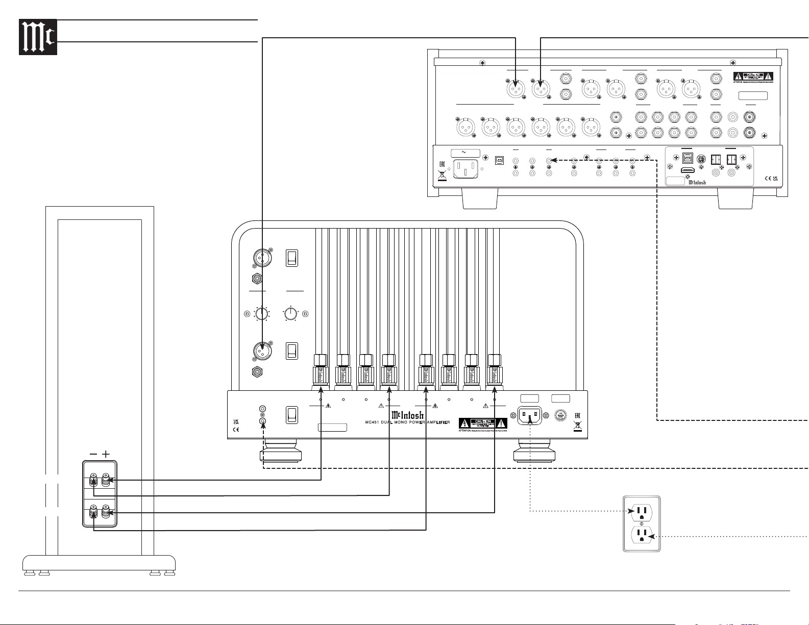
Connection to AC Power should
be the LAST connection made
Right Loudspeaker System
Audio
Preamplier
LOW
MID / HIGH
Connection Diagram
11
SERIAL
NUMBER
CAUTION
RISK OF ELECTRIC SHOCK
DO NOT OPEN
MC 4 5 1 DUA L M O NO PO W E R AMP L I FIE R
McINTOSH LABORATORY, INC., BINGHAMTON, NY
HANDCRAFTED IN USA WITH US AND IMPORTED PARTS
+++
-
8Ω 4Ω 2Ω COM
-
COM
++
4Ω 8Ω
+
2Ω
SOLID STATE (300W) OUTPUTS
CLASS 2 WIRING
VACUUM TUBE (150W) OUTPUTS
CLASS 2 WIRING
POWER
CONTROL
OUT
IN
AUTO OFF
ENABLED
DISABLED
CROSSOVER
(MONO MODE)
VACUUM TUBE
INPUT
INPUT MODE
BALANCED
UNBALANCEDBAL
UNBAL
MONO SOLID STATE/
INPUT
AMPLIFIER MODE
MONO
SEPARATEBAL
UNBAL
300
250 400
550
180
130 800
1k100
CROSSOVER POINT
Hz
+1. 2
-3
+3-6
0
VACUUM TUBE LEVEL
dB
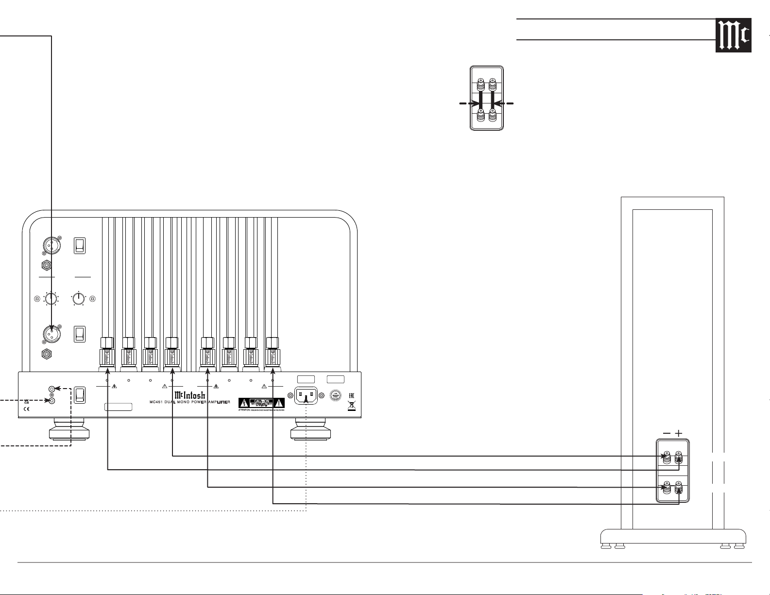
LOW
MID / HIGH
Le Loudspeaker System
Any jumpers between the low
and mid/high sections of the
loudspeakers MUST be removed
prior to connecting the MC451.
REMOVE REMOVE
Connection Diagram
12
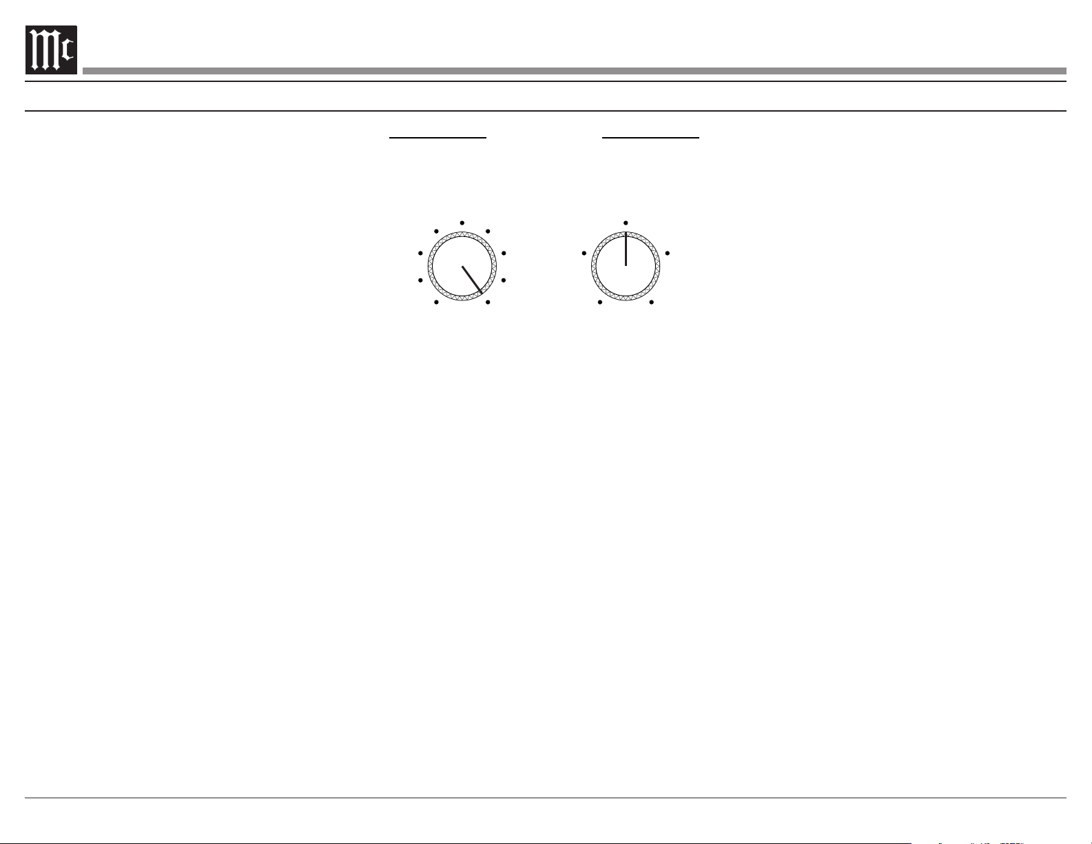
The MC451’s crossover tailors the output
knob to the loudspeaker’s published crossover point.
Frequencies below the crossover point will be sent
CROSSOVER
(MONO MODE)
300
250 400
550
180
130 800
1k100
CROSSOVER POINT
Hz
+1.2
-3
+3-6
0
VACUUM TUBE LEVEL
dB
adjustments to be made to the vacuum tube ampli
-
the low end of the loudspeaker and the mid/high
range.
gain adjustments from -6dB to +3dB. The knob has
a center detent to mark the point of 0dB gain, but
adjustments are continuous from -6dB to 0dB and
0dB to +3dB.
Setting Up the Crossover
13
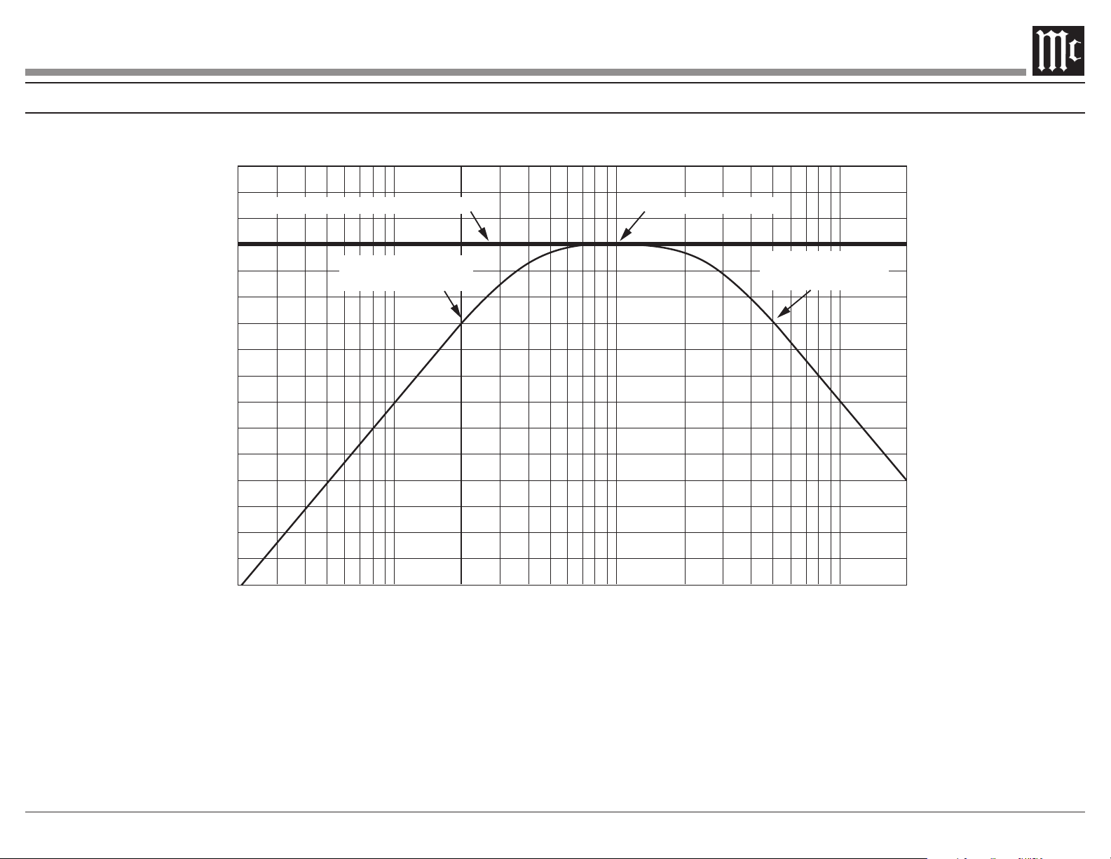
Setting Up the Crossover
+6
+4
+2
0
-2
-4
-6
-8
-10
-12
-14
-16
-18
-20
-22
-24
-26
20 30 50 100 200 300 500 1k 2k 3k 5k 10k
20k
Frequency (Hz)
Decibels
Combined (Full Range) Response Crossover Point (1kHz)
Vacuum Tube
(High Pass) Response
Solid State
(Low Pass) Response

14
Vacuum Tube Specications
Power Output
150 watts into 2 ohm load
150 watts into 4 ohm load
150 watts into 8 ohm load
Rated Power Band
20Hz to 20,000Hz
Dynamic Headroom
1.2dB
Wide Band Damping Factor
Frequency Response
+0, -0.5dB from 20Hz to 20,000Hz
+0, -3.0dB from 10Hz to 70,000Hz
Total Harmonic Distortion
0.5% maximum harmonic distortion at any power
level from 250 milliwatts to rated power, 20Hz to
20,000Hz
Intermodulation Distortion
0.5% maximum, if the instantaneous peak power
output does not exceed twice the rated power output
for any combination of frequencies from 20Hz to
20,000Hz
Signal To Noise Ratio (A Weighted)
112dB below rated output
Input Sensitivity (for rated output)
Volt age Gai n
29dB, 8 ohms
26dB, 4 ohms
23dB, 2 ohms
Input Impedance
22,000 ohms Balanced
22,000 ohms Unbalanced
Solid State Specications
Power Output
300 watts into 2 ohm load
300 watts into 4 ohm load
300 watts into 8 ohm load
Rated Power Band
20Hz to 20,000Hz
Dynamic Headroom
2.5dB
Wide Band Damping Factor
Frequency Response
+0, -0.25dB from 20Hz to 20,000Hz
+0, -3.0dB from 10Hz to 100,000Hz
Total Harmonic Distortion
0.005% maximum harmonic distortion at any power
level from 250 milliwatts to rated power, 20Hz to
20,000Hz
Intermodulation Distortion
0.005% maximum, if the instantaneous peak power
output does not exceed twice the rated power output
for any combination of frequencies from 20Hz to
20,000Hz
Signal To Noise Ratio (A Weighted)
118dB below rated output
Input Sensitivity (for rated output)
Volt age Gai n
29dB, 8 ohms
26dB, 4 ohms
23dB, 2 ohms
Input Impedance
22,000 ohms Balanced
22,000 ohms Unbalanced
General Specications
Power Control Input
Power Control Output
Power Requirements
Standby, less than 0.5 watt
Refer to the rear panel of the MC451 for the
correct voltage.
Overall Dimensions
Weight
133 pounds (60.3kg) net
159 pounds (72.1kg) in shipping carton
Shipping Carton Dimensions
Width is 28 inches (71.1cm)
Depth is 31 inches (78.7cm)
15
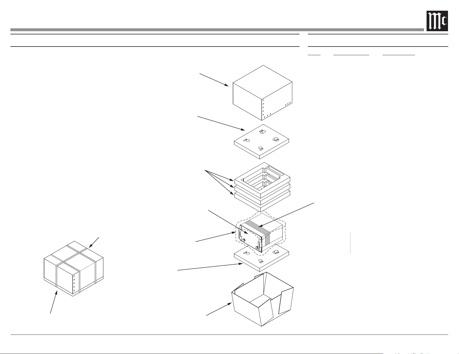
Packing Instructions Packaging Parts List
Qty Description
1 034105 Shipping carton top
1 034104 Shipping carton bottom
3 034678 Foam Ring
1 034705 Tube Foam
In the event it is necessary to repack the equipment
for shipment, the equipment must be packed exactly
as shown below.
It is very important that the four feet are
attached to the bottom of the unit� This will
ensure the proper equipment location on the
bottom pad� Failure to do this will result in
shipping damage�
Use the original shipping carton and interior parts
only if they are all in good serviceable condition.
If a shipping carton or any of the interior part(s)
are needed, please call or write Customer Service
Department of McIntosh Laboratory. Refer to page
Packaging Parts List for the
correct part numbers.
POLY BAG
TOP / BOTTOM
PAD
TOP / BOTTOM
PAD
CARTON TOP
FOAM RING (3)
UNIT WITH
(4) FEET ON
BOTTOM COVER
CARTON BOTTOM
TUBE FOAM
SEAL WITH
PACKAGING T
IMPORTANT
(Read Above)
TUBE FOAM
USE BANDING
STRAPS AS
SHOWN
SEAL WITH
PACKAGING TAPE
ANT
(Read Above)

The continuous improvement of its products is the
policy of McIntosh Laboratory Incorporated who
reserve the right to improve design without notice.
Printed in the U.S.A.
McIntosh Laboratory, Inc.
2 Chambers Street
Binghamton, NY 13903
www.mcintoshlabs.com
McIntosh Part No. 24118600
