McIntosh Laboratory, Inc. 2 Chambers Street Binghamton, New York 13903-2699 Phone: 607-723-3512 www.mcintoshlabs.com
MC3500
Mono Tube Amplifier
Owner's Manual

2
Thank You
Your decision to own this McIntosh MC3500 Tube
Power Amplifier ranks you at the very top among
discriminating music listeners. You now have “The
Best.” The McIntosh dedication to quality is assurance
that you will receive many years of musical enjoyment
from this unit.
Please take a short time to read the information in this
manual. We want you to be as familiar as possible
with all the features and functions of your new
McIntosh.
Please Take A Moment
The serial number, purchase date, and McIntosh
Dealer name are important to you for possible
insurance claims or future service. The spaces below
have been provided for you to record that information:
Important Safety Information is supplied in a separate document “Important Additional Operation Information Guide”
Serial Number: _______________________________
Purchase Date: _______________________________
Dealer Name: _______________________________
Technical Assistance
If at any time you have questions about your McIntosh
product, contact your McIntosh Dealer who is familiar
with your McIntosh equipment and any other brands
that may be part of your system. If you or your Dealer
need additional help concerning a suspected problem,
you can receive technical assistance for all McIntosh
products at:
McIntosh Laboratory, Inc.
2 Chambers Street
Binghamton, New York 13903
Phone: 607-723-3512
Fax: 607-724-0549
Customer Service
If it is determined that your McIntosh product is
in need of repair, you can return it to your Dealer.
You can also return it to the McIntosh Laboratory
Service Department. For assistance on the factory
repair return procedure, contact the McIntosh Service
Department at:
McIntosh Laboratory, Inc.
2 Chambers Street
Binghamton, New York 13903
Phone: 607-723-3515
Fax: 607-723-1917
Table of Contents
Unpacking the MC3500 ............................................4
General Information .................................................6
Connector and Cable Information ............................6
Introduction ...............................................................6
Performance Features ...............................................6
Dimensions ...............................................................7
Navigating the Rear Panel ........................................8
Connection Diagram ................................................. 9
How to Connect Loudspeakers ................................. 10
Navigating the Front Panel ........................................12
How to Operate .........................................................12
Amplifier Specifications ...........................................14
General Specifications .............................................. 14
Packing Instructions .................................................15

3
IMPORTANT!
INSTRUCTIONS FOR REMOVAL
OF FOAM INSERT OVER THE
VACUUM TUBES PRIOR TO
CONNECTING THE A.C. POWER
SUPPLY CORD START ON THE
NEXT PAGE.
4
Unpacking the MC3500
WA R NING: To prevent damage to the MC3500
Vacuum Tubes during shipping, there is a
special foam insert surrounding the Vacuum
Tubes of the Power Amplifier.
The Foam Insert must be removed from the
MC3500 before connecting the AC Power
Supply Cord to the Power Amplifier.
Failure to do so is a Fire Hazard, which could
result in damage to the MC3500 and the
surrounding environment.
Follow these instructions for removal of the
packing foam before connecting the AC Power
Supply Cord to the MC3500.
In order to remove the foam insert surrounding the
Vacuum Tubes on the MC3500, it is necessary to
temporarily remove the Tube Cover. After the foam
insert is removed, the Tube Cover must be reinstalled
for proper and safe operation of the MC3500 Power
Amplifier. The Tube Cover provides protection from
the hazardous voltages inside the MC3500. The
MC3500 has no user serviceable parts, including the
Vacuum Tubes. If repairs are needed, they must be
performed by an authorized McIntosh Service Agency.
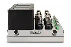
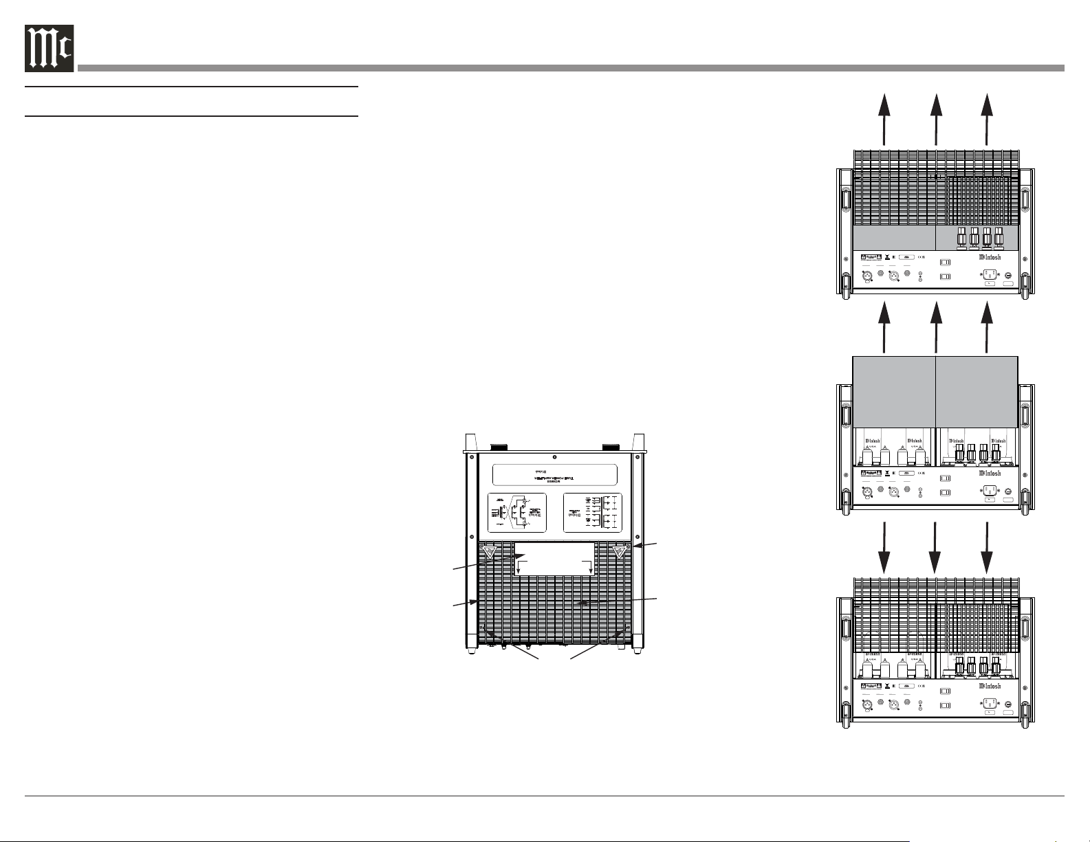
1. Orient the MC3500 so the rear of the Power
Amplifier is facing you and remove the Warning
Sheet. Refer to figure 1.
2. Remove the four screws and the two Hot Surface
Tags located on the top of the Tube Cover by using
a #2 Phillips Head Screw Driver. Refer to figure 1.
3. Place the Tube Cover, Hot Surface Tags, and
screws in a safe location, as the Tube Cover will
be reinstalled.
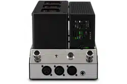
4. Carefully lift up and remove the Tube Cover from
the MC3500. Refer to figure 2.
5. Carefully lift up and remove the Foam Insert from
the MC3500, exposing the Vacuum Tubes. Refer
to figures 3 and 4.
6. Carefully place the Tube Cover back on the
MC3500.
7. Place the Hot Surface Tags in the top corners of
the Tube Cover. Secure the Cover to the MC3500
Chassis using the four screws. Refer to figure 5.
Note: Save the Foam Insert and Warning Sheet with the
MC3500 Shipping Carton for future use.
EL 509 SEL 509 S
EL 509 S
EL 509 S
FUSE
PUSH
PUSH
BALANCED UNBALANCED
INPUTS OUTPUTS
POWER
CONTROL
IN
OUT
MC 350 0 TU BE A MP LIF IE R
McINTOSH LABORATORY, INC., BINGHAMTON, NY
HANDCRAFTED IN USA WITH US AND IMPORTED PARTS
BALANCED UNBALANCED
AUTO OFF
INPUT MODE
ENABLED DISABLED
BALANCED UNBALANCED
120V 50/60Hz
6 AMPS
T8AL 250V
POWER
TRANSFORMER
UNITY COUPLED
OUTPUT
TRANSFORMER
YL
BR
YL
WH
BL
RD
BL
BL +8Ω
YL +4Ω
RD +2Ω
BK COM
POWER 350W
FREQUENCY
15-100kHz
VI
OR
VI
WH WH
MC 3500
TUBE POWER AMPLIFIER
Precision Performance By
DYNAMIC HEADROOM
2.4dB
FREQUENCY
RESPONSE
+ 0,-0.5d B fro m 20 Hz to 20,000Hz
+ 0,-3.0d B fro m 10 Hz to 70,000Hz
A-WEIGHTE D SIGNA LT ONOIS ERATIO
1
20dB
below
rated
output
TOTAL
HARMONIC
DISTORTION
0.3% maximu m harmo nicdistort ion at
any level from 250 mW to rated power output
INPUT SENSITIVITY
1
.9 vol tsunbalanced
3.8 vol ts balanced
POWER OUTPUT
350 watts into an 8, 4 or 2 ohm load is the
minimum sine wave continuous average power
output
McIn tosh Lab orat ory Inc. , Bi ngha mton , Ne w York , U. S.A.
BK
BK
GY
VI
WH
WH
RD
YL
RD
BL
GR
BL
OR
BK
VI
GY
PRI 1
PRI 2
SEC 1
HIGH
VOLTAGE
TCO
SEC 2
HEATERS
TO AVOID A FIRE HAZARD, THE FOAM INSERT
OVER THE VACUUM TUBES MUST BE REMOVED
PRIOR TO CONNECTING THE AC POWER CORD
AND OPERATING THIS PRODUCT.
WARNING
REFER TO THE OWNER’S
MANUAL FOR INSTRUCTIONS.
Shipping
Foam
Hot Surface Tag
Metal Tube Cover
Warning Sheet
Screws
Figure 1
Figure 2
Figure 3
Figure 4
5
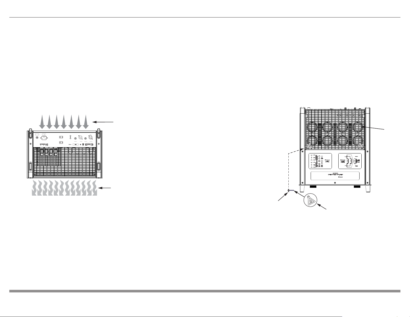
Ventilation
Adequate ventilation extends the trouble-free life of
the MC3500. Always allow air to flow through the
ventilation holes on the bottom of the amplifier and a
means for the warm air to escape at the top. Refer to
figure 6.
Allow at least 19 inches (48.3cm) above the top; 6
inches (15.2cm) for the Front, Rear and Sides; allow
7/8 inch (2.2cm) below the Power Amplifier so airflow
is not obstructed.
Screw
Hot Surface Tag
POWER
TRANSFORMER
UNITY COUPLED
OUTPUT
TRANSFORMER
YL
BR
YL
WH
BL
RD
BL
BL +8Ω
YL +4Ω
RD +2Ω
BK COM
POWER 350W
FREQUENCY
15-100kHz
VI
OR
VI
WH WH
MC 3500
TUBE POWER AMPLIFIER
Precision Performance By
DYNAMIC HEADROOM
2.4dB
FREQUENCY
RESPONSE
+ 0, -0.5d B fro m 20 Hz to 20,000Hz
+ 0, -3.0d B fro m 10 Hz to 70,000Hz
A-WEIGHTE D SIGNA L T ONOIS ERATIO
1
20dB
below
rated
output
TOTAL
HARMONIC
DISTORTION
0.3% maximu m harmo nicdistort ion at
any level from 250 mW to rated power output
INPUT SENSITIVITY
1
.9 vol tsunbalanced
3.8 vol ts balanced
POWER OUTPUT
350 watts into an 8, 4 or 2 ohm load is the
minimum sine wave continuous average power
output
McIn tosh Lab orat ory Inc. , Bi ngha mton , Ne w York , U. S.A.
BK
BK
GY
VI
WH
WH
RD
YL
RD
BL
GR
BL
OR
BK
VI
GY
PRI 1
PRI 2
SEC 1
HIGH
VOLTAGE
TCO
SEC 2
HEATERS
Metal Tube Cover
FUSE
PUSH
PUSH
BALANCED UNBALANCED
INPUTS OUTPUTS
POWER
CONTROL
IN
OUT
MC 350 0 TU BE A MP LIF IE R
McINTOSH LABORATORY, INC., BINGHAMTON, NY
HANDCRAFTED IN USA WITH US AND IMPORTED PARTS
BALANCED UNBALANCED
AUTO OFF
INPUT MODE
ENABLED DISABLED
BALANCED UNBALANCED
120V 50
/
60Hz
6 AMPS
T8AL 250V
Cool Air
Warm Air
Figure 5
Figure 6
6
General Information
1. For additional connection information, refer to the
documentation included with any component(s)
connected to the MC3500.
2. Apply AC Power to the MC3500 and other
components only after all the system components
are connected together. Failure to do so may
cause a malfunction of system operations as the
Microprocessor’s Circuitry inside the components
is active when AC Power is applied.
3. When discarding the unit, comply with local rules
or regulations. Batteries should never be thrown
away or incinerated but disposed of in accordance
with the local regulations concerning battery
disposal.
4. For additional information on the MC3500 and
other McIntosh Products, please visit the McIntosh
Website at www.mcintoshlabs.com.
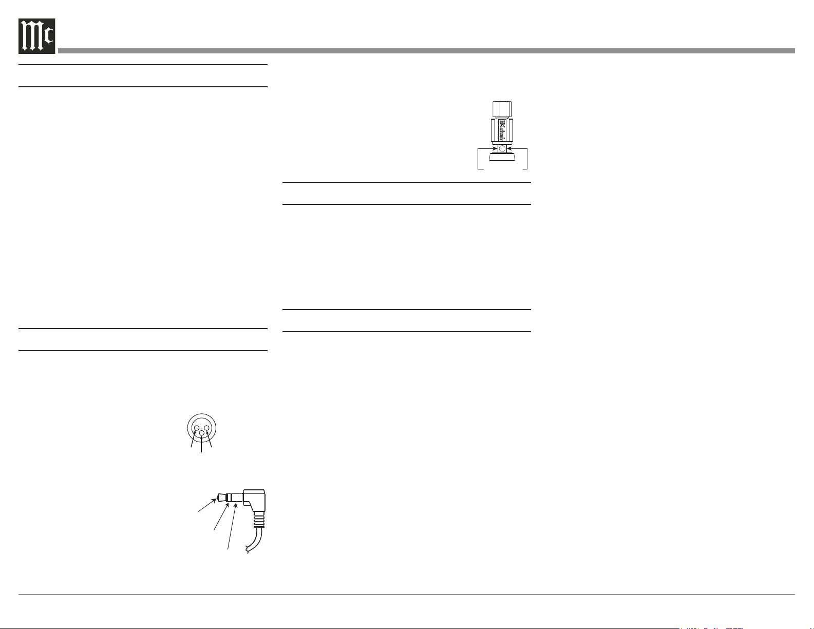
Connector and Cable Information
XLR Connectors
Below is the Pin configuration for the XLR Balanced
Input Connectors on the MC3500. Refer to the
diagram for connection:
PIN 1: Shield/Ground
PIN 2: + Output
PIN 3: - Output
Power Control Connector
The Power Control Input Jack receives Power On/Off
Signals when a component is
connected. The Power Control
Output will in turn provide a +12
volt Output Signal with a current
up to 25 mA. An additional
connection is for controlling
the illumination of the MC3500
Power Meter when connected to a compatible
McIntosh Preamplifier or A/V Control Center Power
Control Output. A 3.5mm stereo mini phone plug is
used for these connections.
Output Terminal Connector
When cables with spade lugs are used
for Loudspeaker Connection, the spade
lugs need an opening of at least 3/10 inch
(7.6mm)
PIN 1
PIN 2
PIN 3
Power
Control
Illumination
Control
Ground
3/10 of an inch
(7.6millimeters)
Introduction
Now you can take advantage of traditional McIntosh
standards of excellence in the MC3500 Tube Power
Amplier. The 350 watt power output will drive any
high quality Loudspeaker System. The MC3500 repro-
duction is sonically transparent and absolutely accu-
rate. The McIntosh Sound is “The Sound of the Music
Itself.”
Performance Features
Power Output
The MC3500 is a Tube Power Amplifier with
a capability of 350 watts into 2-, 4-, or 8-ohm
Loudspeakers with less than 0.3% distortion.
Unity Coupled Circuitry
The MC3500 Power Amplifier uses the famous
McIntosh Patented Unity Coupled Circuit which
provides low distortion, extended frequency response
and cool operating output tubes.
Multifilar Wound Output Transformer
The MC3500 Output Transformer Windings are
part of the Unity Coupled Circuitry. There are three
trifilar wound primaries, one for the cathodes, one
for the plates, and one for the screens. The secondary
winding is wound together with the primary windings.
This provides very close primary to secondary
coupling. The result is flat frequency response and
wide power bandwidth.
Balanced and Unbalanced Input
Balanced connections guard against induced noise and
allow long cable runs without compromising sound
quality.
Sentry Monitor Tube Protection
Sentry Monitor provides protection for the MC3500
by monitoring Output. In the event of a large imped-
ance mismatch, a short circuit at the Output Terminals,
or Tube failure, Sentry Monitor will activate to prevent
potentially destructive levels of current from owing.
Vacuum Tube Sockets
Small Signal Vacuum Tubes Sockets have Ceramic
Base construction with gold plated contacts, providing
protection from atmospheric contamination. Output
Tube Sockets include Air-Pipe cooling at their bases
for long term operation.
Amplifier Gold Plated Connectors
Gold Plated Input Jacks and Output Binding Posts
provide trouble free connections.
Special Power Supply
A very large core Power Transformer and large filter
capacitors ensure stable operation.
Power Guard Screen Grid Sensor (SGS)
Power Guard Screen Grid Sensor™ (SGS) helps
prevent premature Vacuum Tube failure by monitoring
the screen grid current in the EL509S output Vacuum
Tubes. If the current becomes too high, a circuit in
Power Guard SGS™ is activated which then dynami-
cally attenuates the input signal in real time to keep
the Vacuum Tubes operating at safe levels. The right
amber LED will flash when Power Guard
SGS is
engaged in protecting the Vacuum Tubes.
7
EL 509 SEL 509 S
EL 509 S
EL 509 S
FUSE
PUSH
PUSH
BALANCED UNBALANCED
INPUTS OUTPUTS
POWER
CONTROL
IN
OUT
MC3 50 0 TUB E A M P L IFIER
McINTOSH LABORATORY, INC., BINGHAMTON, NY
HANDCRAFTED IN USA WITH US AND IMPORTED PARTS
BALANCED UNBALANCED
AUTO OFF
INPUT MODE
ENABLED DISABLED
BALANCED UNBALANCED
120V 50/60Hz
6 AMPS
T8AL 250V
WATTS
HOLD
LIGH TS
OFF
REMO TE
OFF
O
N
POW ER
MET ER
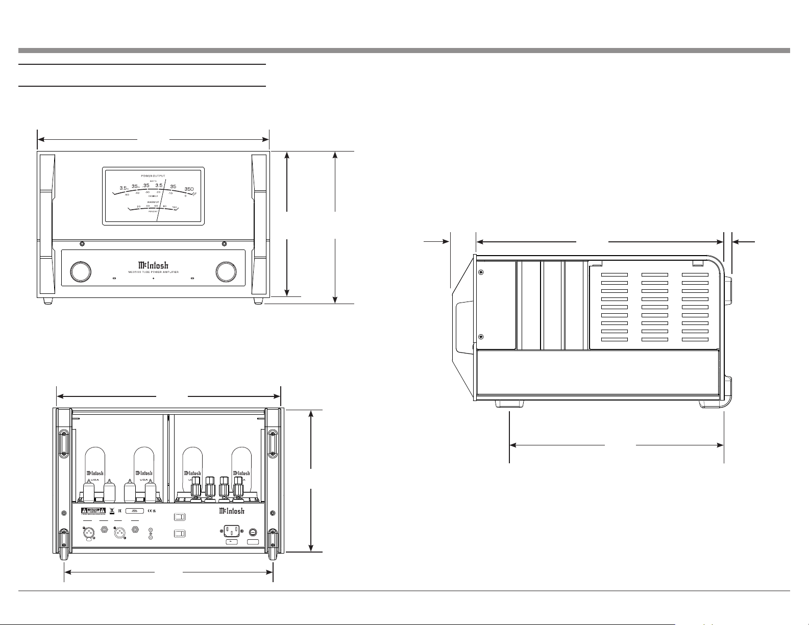
Dimensions
18"
45.7cm
11-5/16"
28.7cm
11-13/16"
30cm
19-3/16"
48.7cm
1-7/8"
4.8cm
16-5/8"
42.2cm
17-1/2"
44.5cm
16-1/4"
41.3cm
Front View
Side View
Rear View
9/16"
1.4cm
11-1/4"
28.6cm
FUSE
PUSH
MC3 50 0 TUB E A M P L IFIER
McINTOSH LABORATORY, INC., BINGHAMTON, NY
HANDCRAFTED IN USA WITH US AND IMPORTED PARTS
120V 50/60Hz
6 AMPS
WATTS
HOLD
LIGH TS
OFF
REMO TE
OFF
O
N
POW ER
MET ER
FUSE
PUSH
MC3 50 0 TUB E A M P L IFIER
McINTOSH LABORATORY, INC., BINGHAMTON, NY
HANDCRAFTED IN USA WITH US AND IMPORTED PARTS
120V 50/60Hz
6 AMPS
WATTS
HOLD
LIGH TS
OFF
REMO TE
OFF
O
N
POW ER
MET ER
POWER GUARD
SGS
WARMUP
8
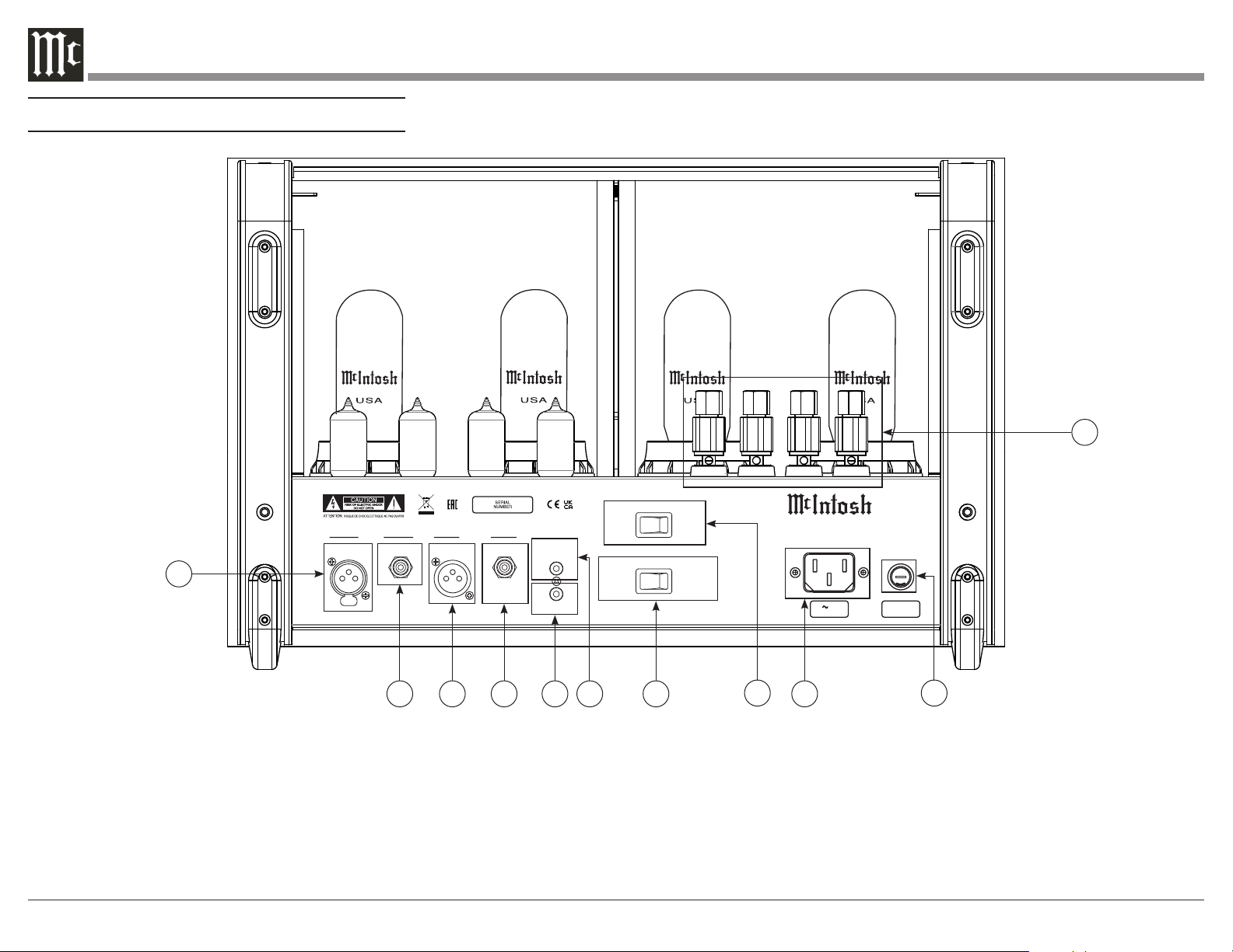
Navigating the Rear Panel
EL509SEL509S
EL509S
EL509S
FUSE
PUSH
PUSH
BALANCED UNBALANCED
INPUTS OUTPUTS
POWER
CONTROL
IN
OUT
MC3 50 0 TUB E A MPL IF IE R
McINTOSH LABORATORY, INC., BINGHAMTON, NY
HANDCRAFTED IN USA WITH US AND IMPORTED PARTS
BALANCED UNBALANCED
AUTO OFF
INPUT MODE
ENABLED DISABLED
BALANCED UNBALANCED
120V 50 /60Hz
6 AMPS
T8AL 250V
1
2 3 4 5 6 7
8
9
10
11
1. Balanced Input: Connect an XLR connector cable
(see Page 6) from an external output device into this
port to amplify a Balanced signal.
2. Unbalanced Input: Connect an RCA connector
cable from an external output device into this port to
amplify an Unbalanced signal.
3. Balanced Output: This port produces a signal from
the Balanced Input using an XLR connector cable (see
Page 6)
4. Unbalanced Output: This port produces a signal
from the Unbalanced Input using an RCA connector
cable.
5. Power Control Out: Sends an On/Off signal to a
connected McIntosh component via a 3.5mm cable
(see Page 6).
6. Power Control In: Receives an On/Off signal from
a connected McIntosh component via a 3.5mm cable
(see Page 6).
7. Input Mode Switch: Switch to toggle between
Balanced and Unbalanced Inputs.
8. Auto Off: Switch to Enable/Disable Auto Off
function.
9. Main Power: Connect to a power outlet using the
included power cable to supply power to the MC3500.
10. Fuse Holder: Houses the fuse to power the unit.
11. Loudspeaker Terminal Posts: Connect
loudspeakers using speaker cable (see Page 10).
9
EL5 0 9 SEL5 0 9 S
EL5 0 9 S
EL5 0 9 S
FUSE
PUSH
PUSH
BALANCED UNBALANCED
INPUTS OUTPUTS
POWER
CONTROL
IN
OUT
MC 3 5 00 T UB E AM P L IF IE R
McINTOSH LABORATORY, INC., BINGHAMTON, NY
HANDCRAFTED IN USA WITH US AND IMPORTED PARTS
BALANCED UNBALANCED
AUTO OFF
INPUT MODE
ENABLED DISABLED
BALANCED UNBALANCED
120V 50/ 60Hz
6 AMPS
T8AL 250V
+
To
AC Power Outlet
-
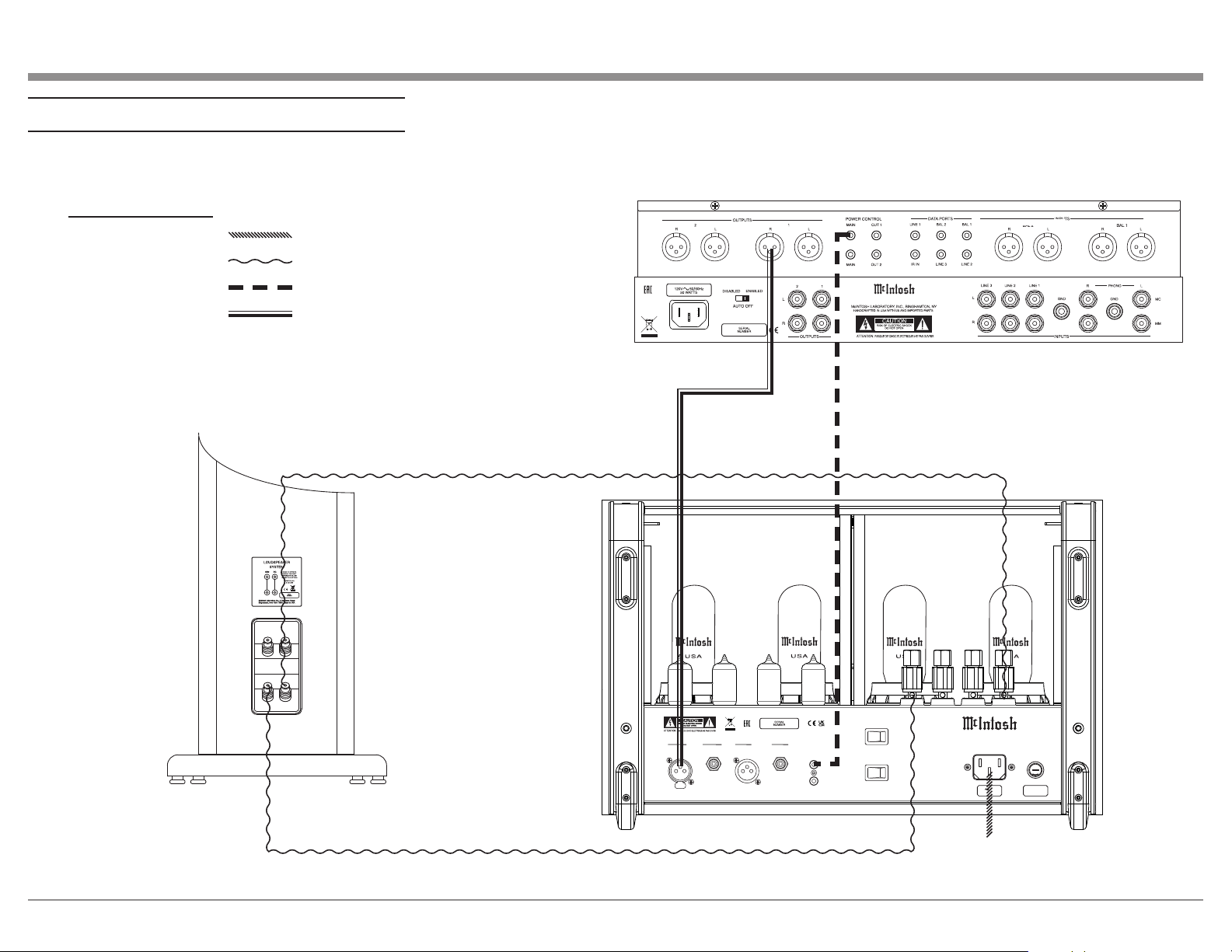
Connection Legend:
AC Power Cable:
Loudspeaker Cable:
Power Control Cable:
Audio Signal Cable:
Connection Diagram
Loudspeaker
Preamplifier
MC3500
10
How to Connect Loudspeakers
For the best performance and safety, it is important to
always match the impedance of the Loudspeaker to
the Power Amplifier connections. When connecting
the Loudspeaker Hookup Cables to the MC3500
Power Amplifier Output Terminals please follow the
steps below:
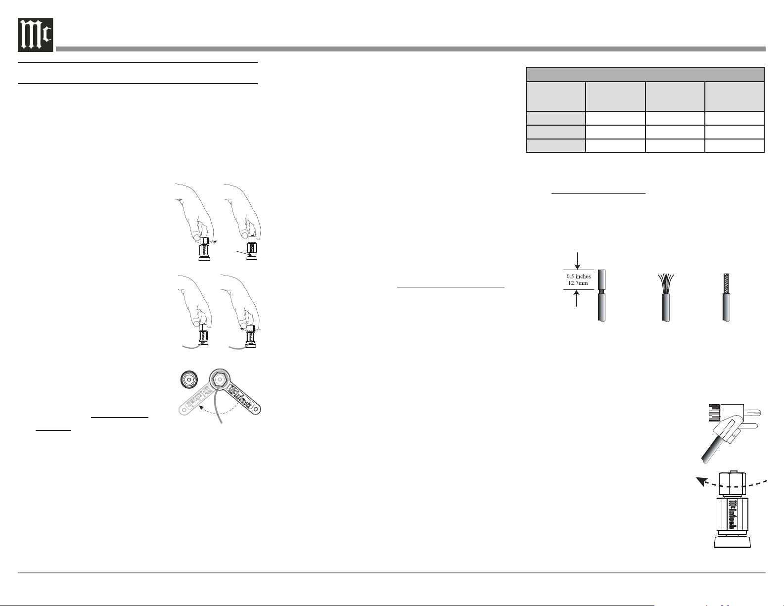
1. Rotate the top of the Output Terminal Post
counterclockwise until an
opening appears. Refer to
gures A and B.
2. Insert the Loudspeaker hookup
cable into the Output Terminal
Post opening or the cable spade
lug around the center post of
the Output Terminal. Refer to
gure C.
3. Rotate the top of the Output
Terminal Post clockwise until it
is nger tight. Refer to gure D.
4. Place the supplied McIntosh
Wrench over the top of the
Output Terminal and rotate it
one quarter of a turn (90°) to
secure the Loudspeaker Cable
Connection. Do not over
tighten. Refer to gure E.
Figure A
Opening
Figure B
Figure C Figure D
Figure E
WA R NING: Do not connect the AC Power Cord
to the MC3500 Rear Panel until after the
Loudspeaker Connections are made. Failure to
observe this could result in Electric Shock.
The connection instructions below, together with the
MC3500 Connection Diagram located on Page 9 is an
example of a typical audio system. Your system may
vary from this; however, the actual components would
Figure 1
Figure 2 Figure 3
Loudspeaker Cable Distance vs Wire Gauge Guide
Loudspeaker
Impedance
25 feet
(7.62 meters)
or less
50 feet
(15.24 meters)
or less
100 feet
(30.48 meters)
or less
2 Ohms
12AWG 10AWG 8AWG
4 Ohms
14AWG 12AWG 10AWG
8 Ohms
16AWG 14AWG 12AWG
3. Prepare the Loudspeaker Hookup Cable for
attachment to the MC3500 Power Amplifier:
Bare wire cable ends:
Carefully remove sufficient insulation from the
cable ends, refer to figures 1, 2, and 3. If the
cable is stranded, carefully twist the strands
together as tightly as possible.
Notes: 1. If desired, the twisted ends can be tinned with
solder to keep the strands together.
2. The prepared bare wire cable ends may be
inserted into spade lug connectors.
3. Banana plugs are for use in the United States
and Canada only.
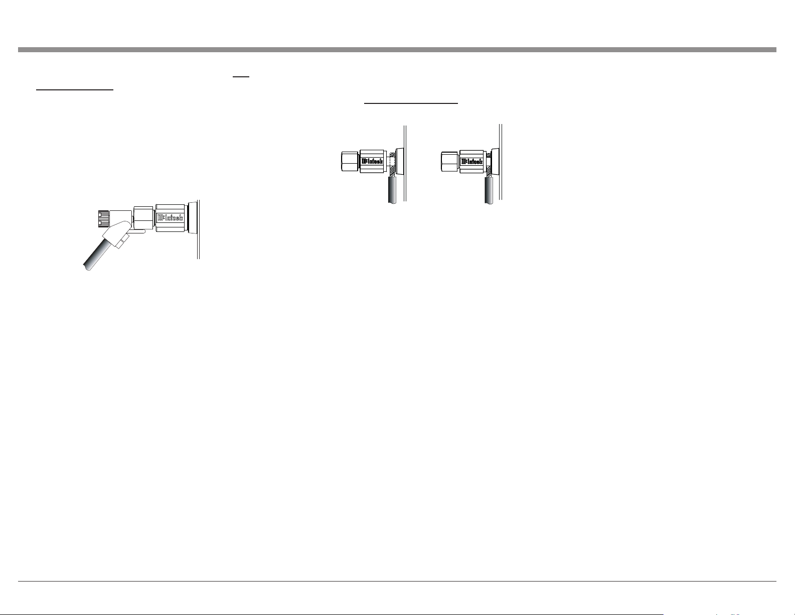
Banana Plugs are for use in the
United States and Canada only:
4. Attach the previously prepared
bare wire cable ends into the
banana plugs and secure the
connections. Refer to figure F.
5. Rotate the top of the Output
Terminal Post clockwise until
it is nger tight. Refer to gure
G. Then using the McIntosh
Wrench, rotate the top of the
Figure F
Figure G
be connected in a similar manner. For additional infor-
mation, refer to “Connector and Cable Information”
on Page 6.
1. For Remote Power Control, connect a power
control cable from the Audio Preamplifier Power
Control Main Output Jack to the Power Amplifier
POWER CONTROL IN Jack.
2. Connect XLR cables from the Balanced Main
Output connector of the Audio Preamplifier to
the Power Amplifier Balanced INPUTS. Place the
INPUT Switch in the Balanced Position.
Note: An optional hookup is to use unbalanced cable
and place the INPUT MODE Switch in the
Unbalanced Position.
This McIntosh MC3500 Power Amplifier is designed
for Loudspeakers with an impedance of 2 ohms, 4
ohms, or 8 ohms. Connect a single Loudspeaker only
to the Output Terminals.
When connecting Loudspeakers to the MC3500 it
is very important to use cables of adequate size, so
there is little to no power loss in the cables. The size
is specified in AWG (American Wire Gauge). The
smaller the Gauge number, the larger the wire size:
Note: The impedance of a Loudspeaker actually
varies as the Loudspeaker reproduces
different frequencies. As a result, the nominal
impedance rating of the Loudspeaker
(usually measured at a midrange frequency)
might not always agree with the impedance
of the Loudspeaker at low frequencies where
the greatest amount of power is required.
Contact the Loudspeaker Manufacturer
for additional information about the actual
impedance of the Loudspeaker before
connecting it to the McIntosh MC3500.
11
tighten the terminal cap until the cable is firmly
clamped into the terminals so the lugs or wire
cannot slip out. Do not over tighten. Refer to
gures 4, 5, and figure E.
If the Loudspeaker’s impedance is in-between the
available connections, use the nearest lower imped-
ance connection.
WA R NING: Loudspeaker terminals are hazardous
live and present a risk of electric shock. For
additional instruction on making Loudspeaker
Connections contact your McIntosh Dealer or
McIntosh Technical Support.
9. For a Stereo system, repeat steps 2-8 for the other
channel.
10. Connect the MC3500 Power Cord to an active
AC outlet.
Figure H
Output Terminal one quarter of a turn (90°). Do
not over tighten. Refer to gure E.
6. Referring to figure H, connect the Loudspeaker
hookup cables with banana plugs into the hole at
the top of the MC3500 Negative (-) and Positive
(+) Output Terminals. The Positive Terminals
are indentified as 2Ω (ohms), 4Ω (ohms) or 8Ω
(ohms) connection to match the impedance of the
Loudspeaker, being careful to observe the correct
polarities.
If the Loudspeaker’s impedance is in-between the
available connections, use the nearest lower imped-
ance connection.
WA R NING: Loudspeaker Terminals are hazardous
live and present a risk of electric shock. For
additional instruction on making Loudspeaker
Connections, contact your McIntosh Dealer or
McIntosh Technical Support.
7. Connect the MC3500 Power Cord to an active AC
outlet.
Spade Lug or Wire Connections:
8. Connect the Loudspeaker hookup cables to
the MC3500 Negative Output Terminal (-) and
Positive Output (+) Terminal indentified as 2Ω
(ohms), 4Ω (ohms) or 8Ω (ohms) connection to
match the impedance of the Loudspeaker, being
careful to observe the correct polarities. Insert
the spade lug connector or prepared section of the
cable end into the terminal side access hole, and
Figure 4
Figure 5
12
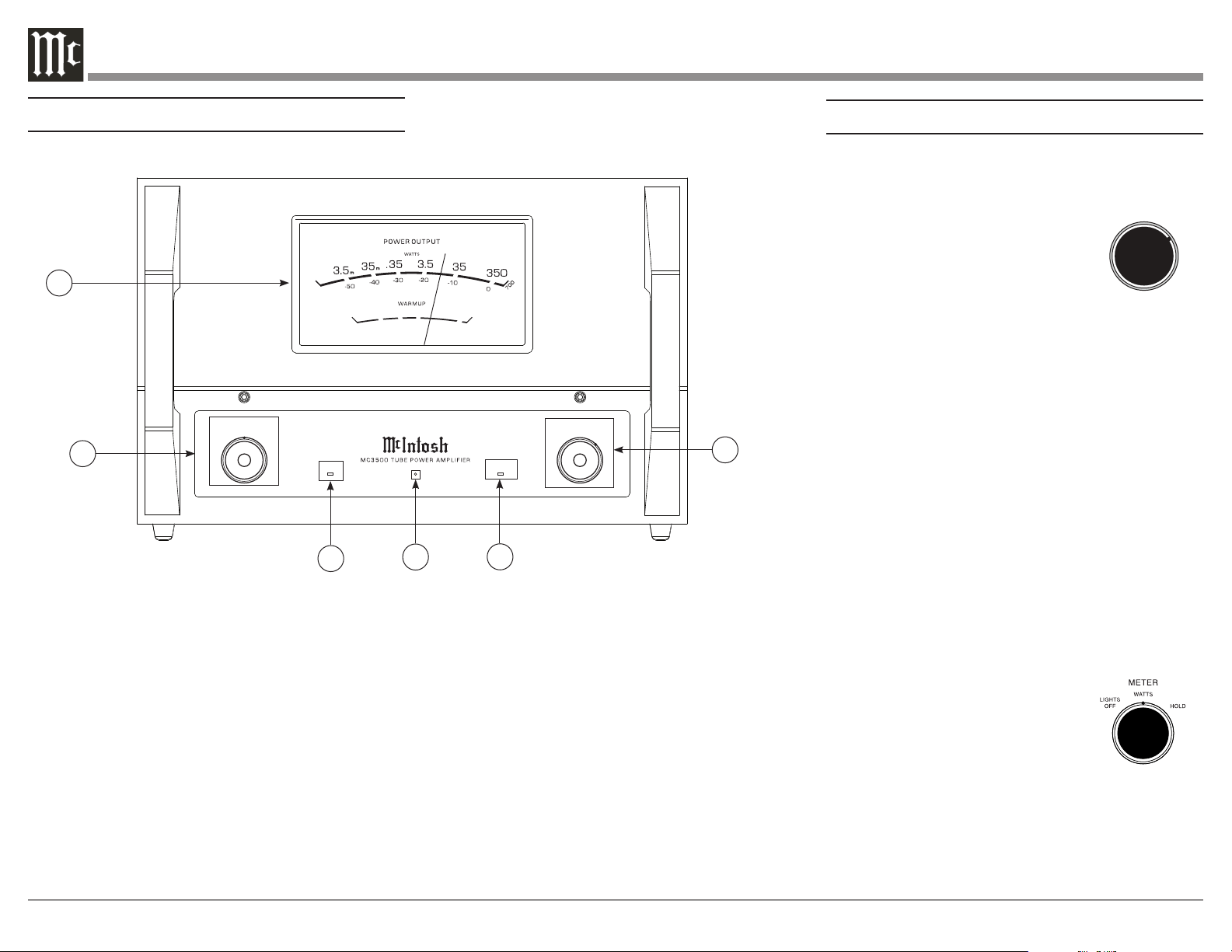
Navigating the Front Panel
How to Operate
Power Control
The POWER CONTROL is located on the Front Panel
of the MC3500. Set the Control to the
REMOTE Position. Refer to figure 10.
The MC3500 Power Amplifier will
turn ON or OFF as the Preamplifier it
is connected to (via the Power Control
Connection) turns On or Off . For
manual operation, place the POWER
CONTROL to the ON Position as desired. The LED
indicator located on the Front Panel is illuminated
when the MC3500 is connected to an active AC
Outlet.
When the MC3500 is first switched On, there is a
Warmup period of time during which no sound will be
heard and the WARMUP LED will illuminate. During
this period, the Power Output Meter needle will
gradually rise to show the warmup percentage. After
the needle reaches 100%, the MC3500 will begin
playing sound, the WARMUP LED will switch off,
and the needle will return to displaying the appropri-
ate Output based on the Meter Control Knob position
(see below).
Meter Control
The Meter Control Knob changes how the Power
Output Meter behaves. If the Knob is set to WATTS,
the Meter will continuously respond to and display
the current Output of the MC3500.
Refer to figure 11.
If the Knob is set to HOLD, the
Meter will display the highest peak
Output in a series of peaks, until a
greater peak is read. If no greater
peak is read, the Meter will begin to
lower at a rate of approximate 6dB per minute.
Fig ure 11
WATTS
HOL D
LIG HTS
OFF
REM OTE
OFF
ON
POWER
METER
POWER GUARD
SGS
WARMUP
D E C I B EL S
2 0
10 0
8 0
6 0
P E R C E NT
4 0
1
2
3
4 5
1. Power Output Meter: Displays power output level
in Watts and Decibels.
2. Meter Control Knob: Select between the different
Output Meter functions (see next page).
3. Warmup LED: Illuminates to indicate when
Warmup state is active (see next page).
4. Standby LED: Illuminates whenever the MC3500
is connected to a live AC outlet. Flashes whenever
Sentry Monitor has activated (see next page).
5. Power Guard LED: Illuminates to indicate when
Power Guard is active.
6. Power Knob: Turn MC3500 On/Off, or set to
REMOTE position to have it be turned On/Off
automatically by a Preamplifier (see next page).
6
REMOTE
OFF
ON
POWER
Figure 10

13
Sentry Monitor Reset
Sentry Monitor provides protection for the MC3500 by
monitoring Output. In the event of a large impedance
mismatch, a short circuit at the Output Terminals, or
Tube failure, Sentry Monitor will activate to prevent
potentially destructive levels of current from flowing.
When Sentry Monitor is activated, the MC3500 will
power off, and the Standby LED will flash.
To reset the Sentry Monitor Protection Circuitry, turn
the Power Control Knob to OFF. (See “Power Control”
on previous page). Then, turn the Power Control Knob
to ON.
If Sentry Monitor continues to engage, the problem
must be fixed before continuing. Check that
wires connected to the Output Terminals and the
Loudspeaker Terminals are not shorted. If those
connections are fine, and the Impedance of the
Loudspeakers is close to the value of the connected
Output terminals, the issue may be a defective tube.
When the MC3500 doesn’t return to Normal
Operation after the Power Switch has been switched
back ON, then place the Power Switch in the OFF
position and disconnect the AC Power Cord from
the MC3500. Then contact your McIntosh Dealer for
repair of the Power Amplifier.
While the Knob is set to either WATTS or HOLD, the
Power Output Meter light will be powered On/Off by
a Preamplifier or A/V Control Center connected by
a Power Control Cable if that unit has Power Control
capabilities.
If the Knob is set to LIGHTS OFF, the Power Output
Meter light will be permanently off, and the Meter
will respond as if the Knob was set to WATTS.
Input Switch
The Input Mode Switch, which is
located on the Rear Panel of the
MC3500, allows selection of either
the Balanced or Unbalanced Input.
Refer to figure 12.
Auto Off Switch
The MC3500 incorporates Power Save Circuitry to
automatically place the MC3500 into the power saving
Standby Mode approximately 30 minutes after there
has been an absence of an audio input signal.
When there is a Power Control
Connection between the MC3500
and a Preamplifier with Power
Save Circuitry, the AUTO OFF
Switch is bypassed (located on the
Rear Panel of the MC3500). Refer to figure 13.
In the event there is no Power Control Connection and
the Power Save Circuitry is activating inappropriately
relative to your specific use of the MC3500, place the
AUTO OFF Switch in the DISABLED position.
If the Power Save Circuitry has switched Power to the
MC3500 OFF, place the POWER in the OFF Position
and then in the ON position to reset the circuitry.
Figure 12
BALANCED
UNBALANCED
INPUT MODE
ENABLED
DISABLED
Figure 13
AUTO OFF

14
Amplier Specications
Power Output
350 watts into 2 ohm load
350 watts into 4 ohm load
350 watts into 8 ohm load
Rated Power Band
20Hz to 20,000Hz
Dynamic Headroom
2.4dB
Wide Band Damping Factor
Greater than 25
Frequency Response
+0, -0.5dB from 20Hz to 20,000Hz
+0, -3.0dB from 10Hz to 70,000Hz
Total Harmonic Distortion
0.3% maximum harmonic distortion at any power level
from 250 milliwatts to rated power, 20Hz to 20,000Hz
Intermodulation Distortion
0.3% maximum, if the instantaneous peak power output
does not exceed twice the rated power output for any
combination of frequencies from 20Hz to 20,000Hz
Signal To Noise Ratio (A Weighted)
120dB below rated output
Input Sensitivity (for rated output)
3.8 Volts Balanced
1.9 Volts Unbalanced
Volt ageGain
29dB, 8 Ohms
26dB, 4 Ohms
23dB, 2 Ohms
Input Impedance
22,000 ohms Balanced
22,000 ohms Unbalanced
General Specications
Power Control Input
5-15VDC, less than 1mA
Power Control Output
12VDC, 25mA (Delayed 0.2 seconds from power on)
Power Requirements
100 Volts ~ 50/60Hz at 7.2 Amps
110 Volts ~ 50/60Hz at 6.0 Amps
120 Volts ~ 50/60Hz at 6.0 Amps
127 Volts ~ 50/60Hz at 6.0 Amps
220 Volts ~ 50/60Hz at 3.3 Amps
230 Volts ~ 50/60Hz at 3.3 Amps
240 Volts ~ 50/60Hz at 3.3 Amps
Standby, less than 0.5 watt
Refer to the rear panel of the MC3500 for the correct
voltage.
Overall Dimensions
Depth is 21-5/8 inches (54.9cm)
Width is 18 inches (45.7cm)
Height is 11-13/16 inches (30cm)
Weight
121 pounds (54.9kg) net
147 pounds (66.7kg) in shipping carton
Shipping Carton Dimensions
Depth is 31 inches (78.7cm)
Width is 28 inches (71.1cm)
Height is 17-1/4 inches (43.8cm)
15
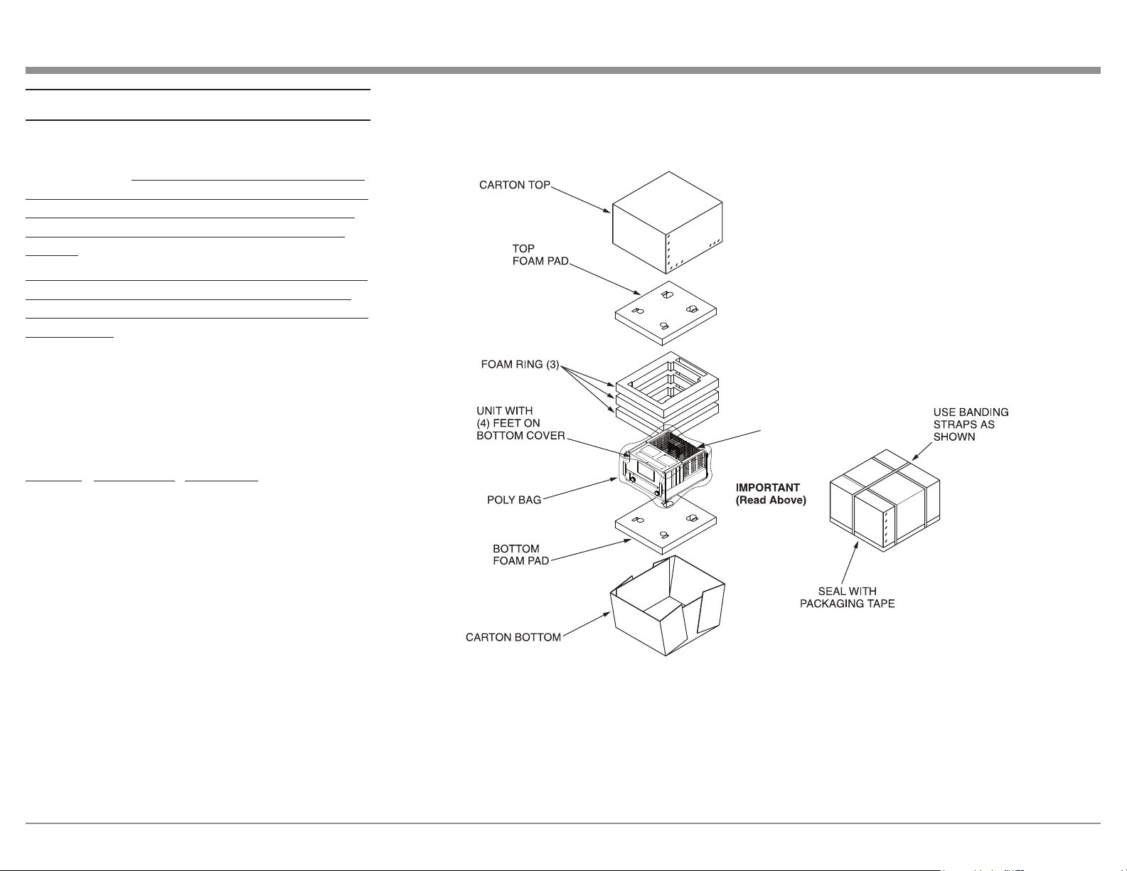
Packing Instructions
In the event it is necessary to repack the equipment
for shipment, the equipment must be packed exactly
as shown below. It is very important that the four feet
are attached to the bottom of the equipment. This will
ensure the proper equipment location on the bottom
foam pad. Failure to do this will result in shipping
damage.
To protect the tubes during shipment, the Foam Insert
removed from the MC3500 needs to be re-inserted.
Follow the unpacking instructions on pages 4-5 in the
reverse order.
Use the original shipping carton and interior parts
only if they are all in good serviceable condition.
If a shipping carton or any of the interior part(s)
are needed, please call or write Customer Service
Department of McIntosh Laboratory, refer to page 2.
Please see the Part List for the correct part numbers.
Quantity Part Number Description
1 034105 Shipping Carton Top
1 034104 Shipping Carton Bottom
1 034680 Tube Foam Insert
2 034679 Pad Top/Bottom
3 034678 Foam Ring
1 241109 Warning Sheet
1 033739 Poly Bag
WARNING SHEET
& TUBE FOAM

The continuous improvement of its products is the
policy of McIntosh Laboratory Incorporated who
reserve the right to improve design without notice.
Printed in the U.S.A.
McIntosh Laboratory, Inc.
2 Chambers Street
Binghamton, NY 13903
www.mcintoshlabs.com
McIntosh Part No. 24113800