Loading ...
Loading ...
Loading ...
Installation Step 10 I
Install the Safety Reversing Sensor
I
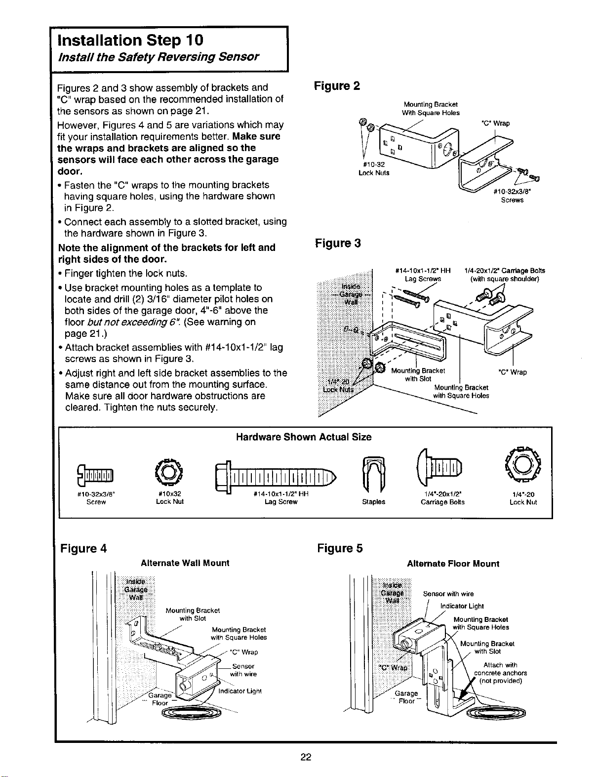
Figures 2 and 3 show assembly of brackets and
"C" wrap based on the recommended installation of
the sensors as shown on page 21.
However, Figures 4 and 5 are variations which may
fit your installation requirements better. Make sure
the wraps and brackets are aligned so the
sensors will face each other across the garage
door.
• Fasten the "C" wraps to the mounting brackets
having square holes, using the hardware shown
in Figure 2.
• Connect each assembly to a slotted bracket, using
the hardware shown in Figure 3.
Note the alignment of the brackets for left and
right sides of the door.
• Finger tighten the lock nuts,
• Use bracket mounting holes as a template to
locate and drill (2) 3/16" diameter pilot holes on
both sides of the garage door, 4"-6" above the
floor but not exceeding 6". (See warning on
page 21 .)
• Attach bracket assemblies with #14-10x1-1/2" lag
screws as shown in Figure 3.
• Adjust right and left side bracket assemblies to the
same distance out from the mounting surface.
Make sure all door hardware obstructions are
cleared. Tighten the nuts securely.
Figure 2
#10-32
Lock Nuts
Figure 3
Mounting Bracket
With Square Holes
#14-10x1-1/2" HH
"C" Wrap
#10-32;<3/8"
Screws
1/4-20xl/2" CarriageBolls
(withsquareshoulder)
"C" Wrap
Mounting Bracket
with Square Holes
©
#10-32x3/8" #10x32
Screw Lock Nut
Hardware Shown Actual Size
©
,,..o
Lag Screw Staples Carr_,ge Boits Lock Nut
Figure 4
Alternate Wall Mount
Mounting Bracket
with Slot
Mounting Bracket
with Square Holes
with wire
Indicator Light
Figure 5
Alternate Floor Mount
iiiiiii_iiii_iiiiii_iii
_i i Sensor with wire
::::::::::_:::::::: Indicator Light:::::::::::::::::: ::
::::::::::::::::::::
Mounting Bracket
Mounting Bracket
• with Slot
Attach with
concrete anchors
22
Loading ...
Loading ...
Loading ...