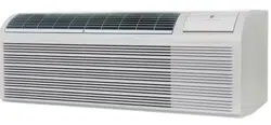
WallMaster®PTAC
PackagedTerminalAirConditioners& Heat Pumps
• Standard
• RemoteThermostat
• SeacoastProtected
Installation& OperationManual
920-087-02 (9-03)
920-087-02(9-03)
Tableof Contents
UnitComponents......................................................................................................................................................................................... 2
P-SeriesAnnouncement/Model NumberCode............................................................................................................................................ 3
InstallationRecommendations.................................................................................................................................................................... 4
DrainKit Installation ................................................................................................................................................................................ 5-6
Wall SleeveInstallation............................................................................................................................................................................ 7-8
DeepWall Installation .................................................................................................................................................................................. 9
Standard GrilleInstallation ........................................................................................................................................................................ 10
InstallationChecklist................................................................................................................................................................................. 11
Electrical RatingTables.............................................................................................................................................................................. 11
ChassisInstallation............................................................................................................................................................................. 12-13
Standard Unit Operations.......................................................................................................................................................................... 14
TemperatureLimitingThermostat .............................................................................................................................................................. 14
HeatingControl(Heat Pumps& Emergency Heat)..................................................................................................................................... 15
FanCycleSwitch....................................................................................................................................................................................... 15
FreshAirVent Control................................................................................................................................................................................ 15
AirDischargeGrille .................................................................................................................................................................................... 16
Start-up Checklist...................................................................................................................................................................................... 16
AppendixA: RemoteThermostatWiring............................................................................................................................................... 17-18
AppendixB: ElectricalWiringfor 265 V Models........................................................................................................................................ 19
RoutineMaintenance................................................................................................................................................................................ 20
BasicTroubleshootingTechniques............................................................................................................................................................. 21
Accessories......................................................................................................................................................................................... 22-23
Warranty................................................................................................................................................................................................... 24
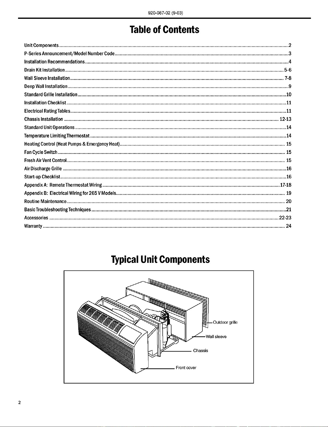
TypicalUnit Components
Chassis
tcover
2
920-087-02 (9-03)
Announcing the FriedrichP-Series PackagedTerminalAir Conditioner.
A new approach to reliability and efficiency. A totally redesigned Friedrich PTAC.
Thank you for your decision to purchase the newly designed Friedrich Packaged Terminal Air Conditioner
(PTAC). We are confident that you will find this unit a quiet and efficient example of Friedrich reliability.
This Installation and Operation Manual has been designed to insure maximum satisfaction in the performance
of your unit. For years of trouble-free service, please follow the installation instructions closely. We cannot
overemphasize the importance of proper installation. We have added new information to the basic instructions
to help you achieve success.
Remember, proper installation is not difficult but it is essential.
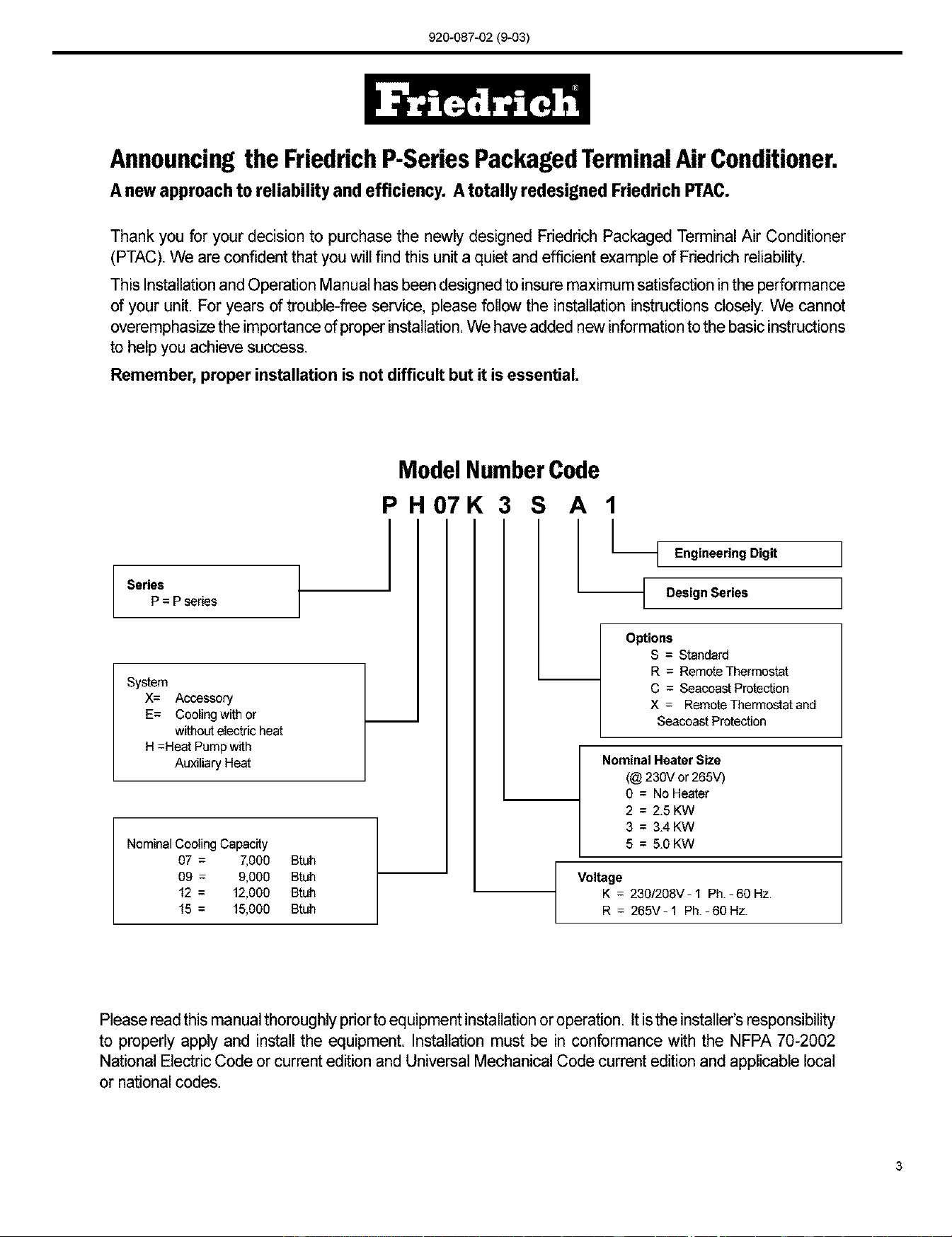
Series
P = P series
System
X= Accessory
E= Coolingwith or
withoutelectric heat
H =Heat Pumpwith
Auxiliary Heat
NominalCooling Capac_y
07 = _000 Btuh
09 = 9,000 Btuh
12 = 12,000 Btuh
15 = 15,000 Btuh
Model NumberCode
PH07K 3 S A 1
L
I Engineering Digit I
I Design sedes I
Options
S = Standard
R = RemoteThermostat
C = SeacoastProtection
X = RemoteThermostatand
Seacoast Protection
Nominal HeaterSize
(@ 230V or 265V)
0 = No Heater
2 = 2.5 KW
3 = 3.4 KW
5 = 5.0 KW
Voltage
K = 230/208V-1Ph.-60 Hz.
R = 265V-1Ph.-60 Hz.
Please read this manual thoroughly prior to equipment installation or operation. It is the installer's responsibility
to properly apply and install the equipment. Installation must be in conformance with the NFPA 70-2002
National Electric Code or current edition and Universal Mechanical Code current edition and applicable local
or national codes.
3
920-087-02 (9-03)
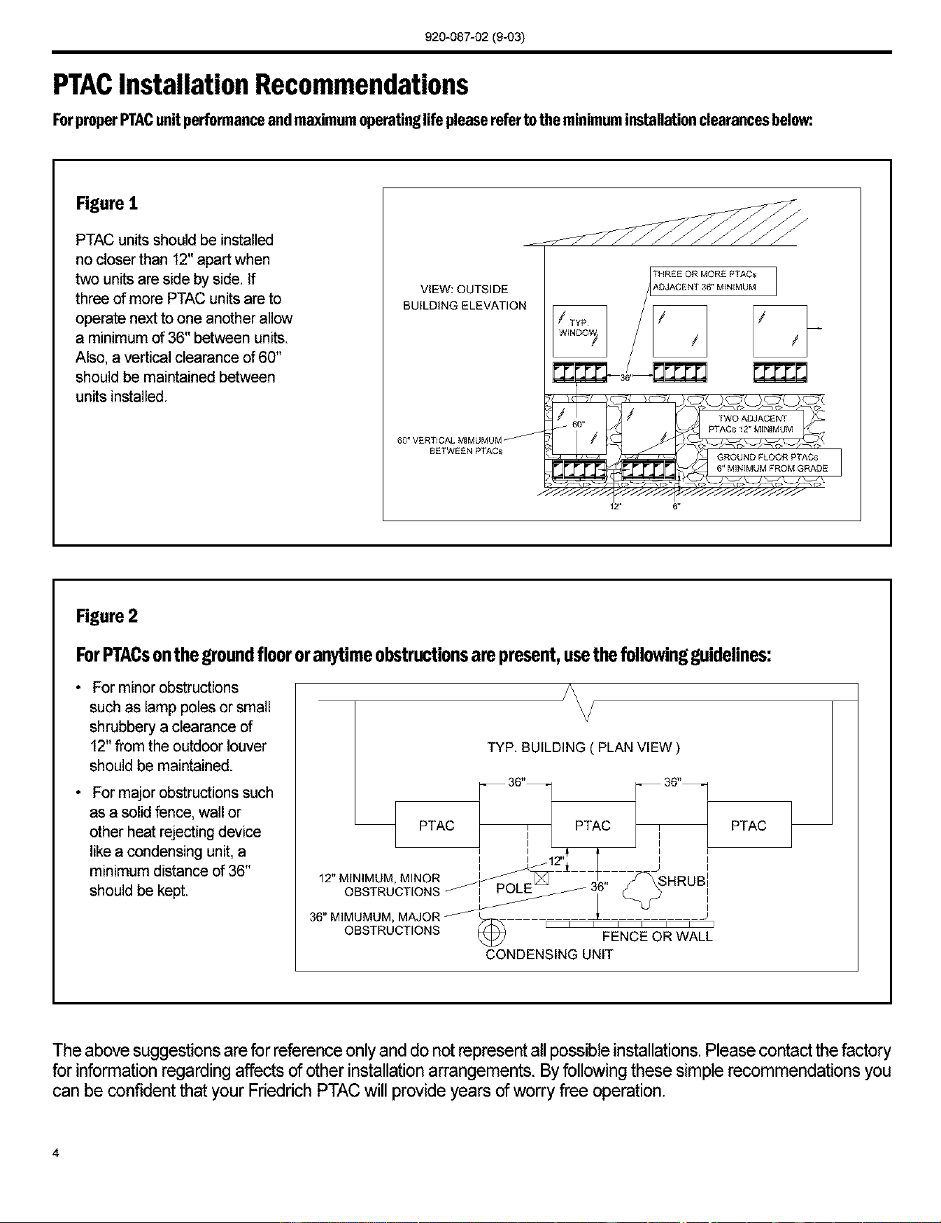
PTACInstallation Recommendations
ForproperPTACunitperformanceandmaximumoperatinglifepleasereferto the minimuminstallationclearancesbelow:
Figure I
PTAC units should be installed
no closer than 12" apart when
two units are side by side. If
three of more PTAC units are to
operate next to one another allow
a minimum of 36" between units.
Also, a vertical clearance of 60"
should be maintained between
units installed.
VIEW: OUTSIDE
BUILDING ELEVATION
60" VERTICAL M]MUMUM
BETWEEN PTACs
THREE OR MORE PTACs
#,DJACENT 36" MINIMUM
GROUND FLOOR PTACs
6" MINIMUM FROM GRADE
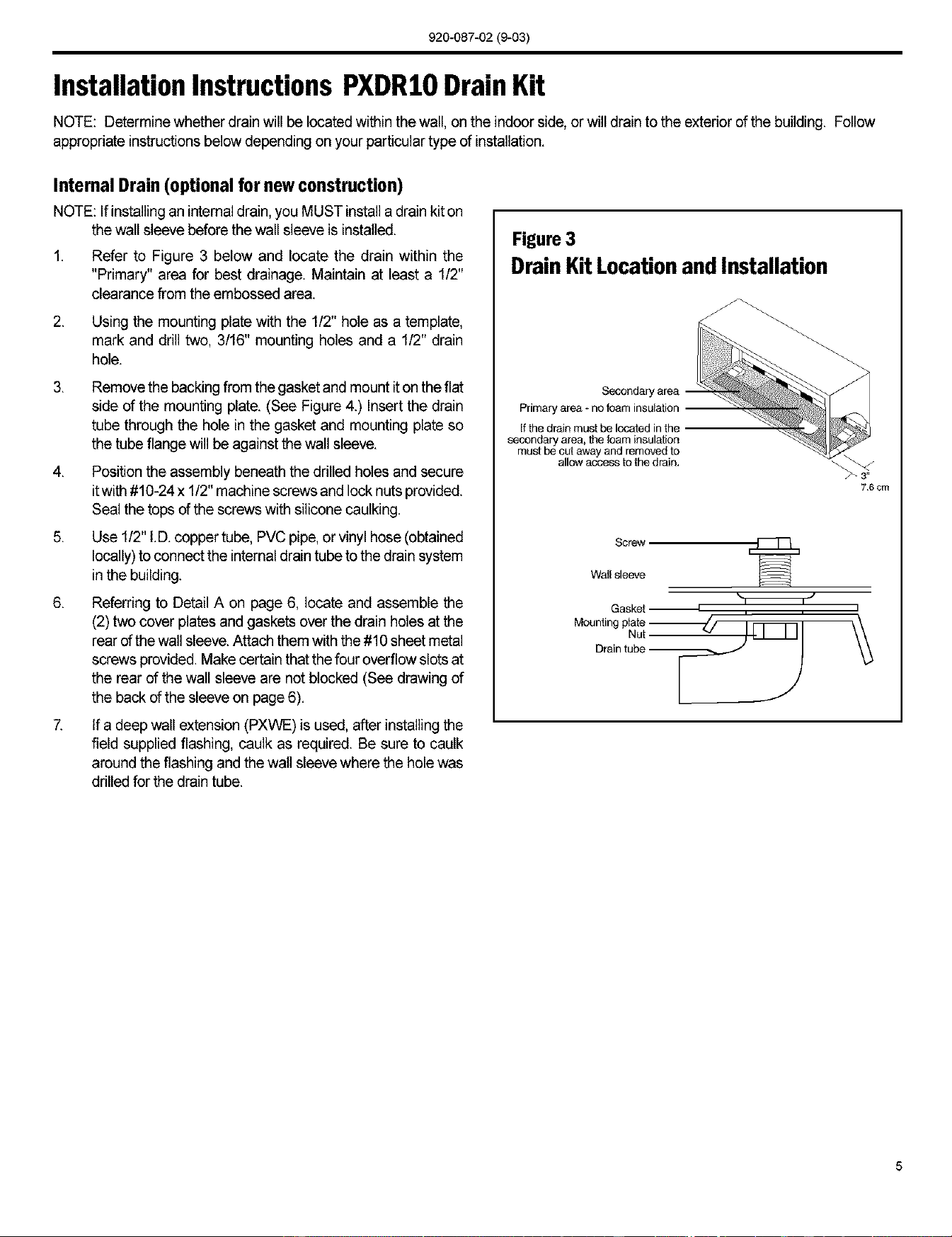
Figure 2
ForPTACsonthegroundfloororanytimeobstructionsarepresent,usethefollowingguidelines:
• For minor obstructions
such as lamp poles or small
shrubbery a clearance of
12" from the outdoor louver
should be maintained.
• For major obstructions such
as a solid fence, wall or
other heat rejecting device
like a condensing unit, a
minimum distance of 36"
should be kept.
TYP. BUILDING ( PLAN VIEW )
-- 36"_] [_ 36"--
PTAC 7 PTAC r
I I
I I
I I
I I
12" MINIMUM, MINOR
OBSTRUCTIONS _ 36"
36" MIMUMUM, MAJOR _
OBSTRUCTIONS _) ' ' ' FENCE OR WALL'
CONDENSING UNIT
PTAC
The above suggestions are for reference only and do not represent all possible installations. Please contact the factory
for information regarding affects of other installation arrangements. By following these simple recommendations you
can be confident that your Friedrich PTAC will provide years of worry free operation.
4
920-087-02(9-03)
Installation Instructions PXDRIO Drain Kit
NOTE: Determine whetherdrain willbe located within the wall, on the indoor side, or will drain to the exterior of the building. Follow
appropriate instructions below depending on yourparticular type of installation.
Internal Drain (optional for new construction)
NOTE: Ifinstalling an internal drain, you MUST install a drain kit on
the wall sleeve before the wall sleeve is installed.
1,
Refer to Figure 3 below and locate the drain within the
"Primary" area for best drainage. Maintain at least a 1/2"
clearance from the embossed area.
2.
Using the mounting plate with the 1/2" hole as a template,
mark and drill two, 3/16" mounting holes and a 1/2" drain
hole.
,
Remove the backingfrom the gasket and mount it on the flat
side of the mounting plate. (See Figure 4.) Insert the drain
tube through the hole in the gasket and mounting plate so
the tube flange will be against the wall sleeve.
4. Position the assembly beneath the drilled holes and secure
it with #10-24 x 1/2" machine screws and lock nuts provided.
Seal the tops of the screws with silicone caulking.
5. Use 1/2" I.D.copper tube, PVC pipe, or vinyl hose (obtained
locally) to connect the internal drain tube to the drain system
in the building.
6. Referring to Detail A on page 6, locate and assemble the
(2) two cover plates and gaskets over the drain holes at the
rear of the wall sleeve.Attach them with the #10 sheet metal
screws provided. Makecertain that the four overflow slots at
the rear of the wall sleeve are not blocked (See drawing of
the back of the sleeve on page 6).
7. If a deep wall extension (PXWE) is used, after installing the
field supplied flashing, caulk as required. Be sure to caulk
around the flashing and the wall sleeve where the hole was
drilled for the drain tube.
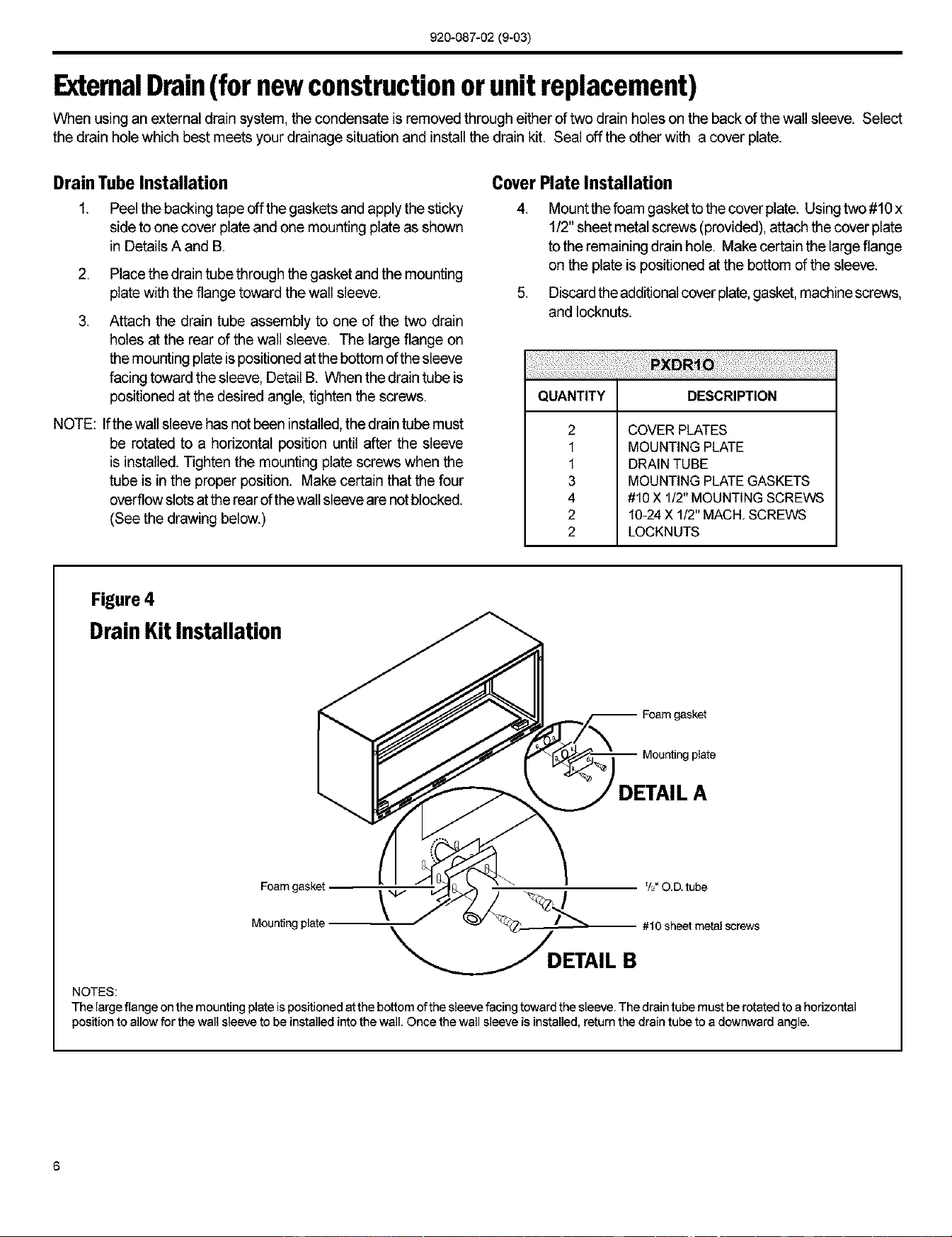
Figure 3
DrainKitLocationandInstallation
Secondary area
Primary area _ no foam insulation --
If the drain must be located in the
secondary area, the foam insulation
must be cut away and removed to
allow access to the drain,
76 cm
Screw [_
Wail sleeve
Gasket t t
i
Mounting plateNut _ j _ I \\
)
5
920-087-02 (9-03)
ExtemalDrain(for newconstructionorunit replacement)
When using an external drain system, the condensate is removed through either of two drain holes on the back of the wall sleeve. Select
the drain hole which best meets your drainage situation and install the drain kit. Seal off the other with a cover plate.
Drain Tube Installation
1. Peelthe backing tape off the gaskets and apply the sticky
side to one cover plate and one mounting plate as shown
in Details A and B,
2. Place the drain tube through the gasket and the mounting
plate with the flange toward the wall sleeve.
3. Attach the drain tube assembly to one of the two drain
holes at the rear of the wall sleeve. The large flange on
the mounting plate ispositionedatthe bottom of the sleeve
facing toward the sleeve, Detail B. When the drain tube is
positioned at the desired angle, tighten the screws.
NOTE: Ifthe wall sleeve has not been installed,the draintube must
be rotated to a horizontal position until after the sleeve
is installed. Tighten the mounting plate screws when the
tube is in the proper position. Make certain that the four
overflow slotsat the rearof the wall sleeveare not blocked.
(See the drawing below.)
Cover Plate Installation
4. Mountthefoamgaskettothecoverplate. Usingtwo#10x
1/2"sheet metal screws (provided), attach the cover plate
to the remaining drainhole. Make certain the largeflange
on the plate is positioned at the bottom of the sleeve.
5. Discardthe additionalcoverplate,gasket,machinescrews,
and Iocknuts.
QUANTITY DESCRIPTION
2
1
1
3
4
2
2
COVER PLATES
MOUNTING PLATE
DRAIN TUBE
MOUNTING PLATE GASKETS
#10 X 1/2" MOUNTING SCREWS
10-24 X 1/2" MACH, SCREWS
LOCKNUTS
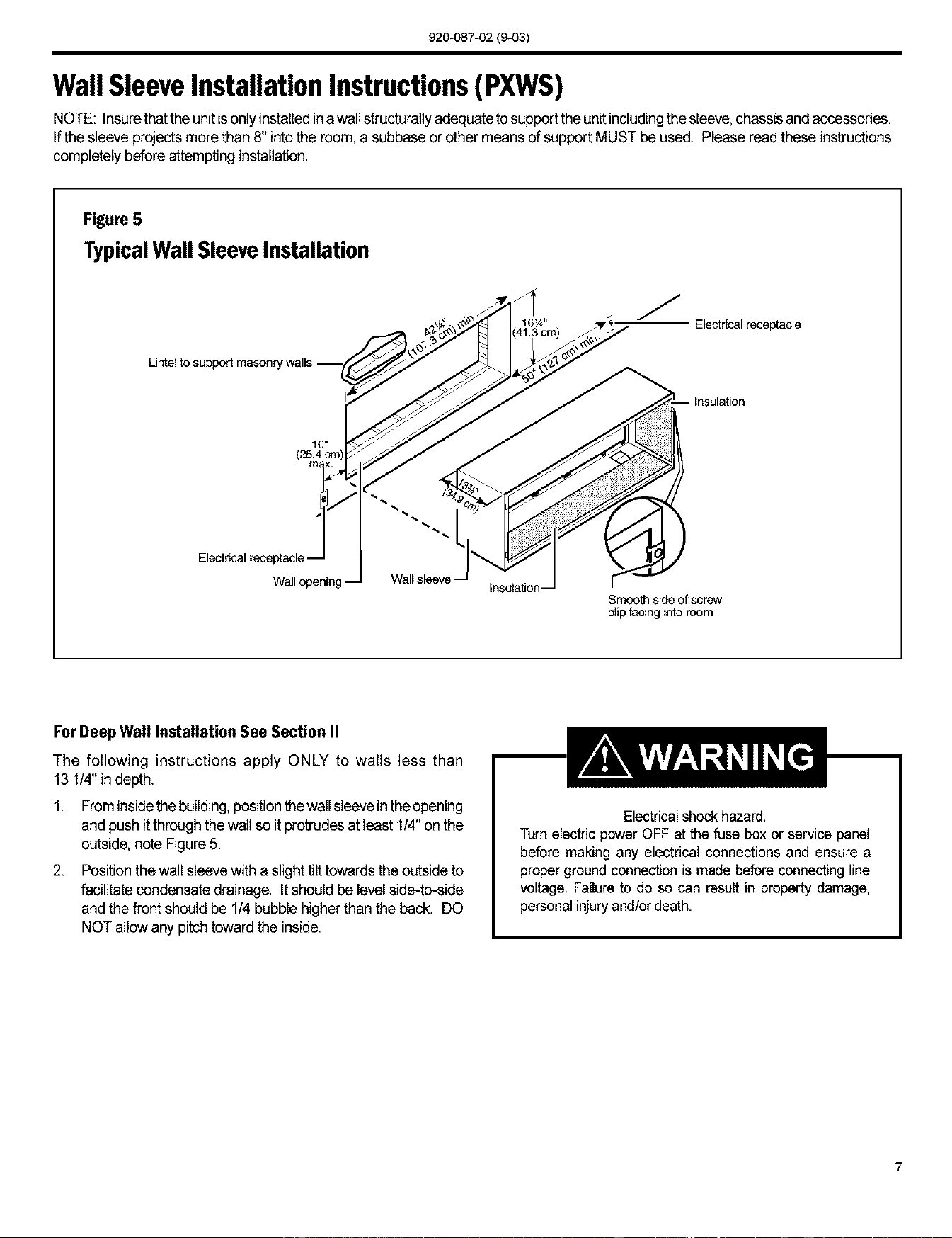
Figure 4
DrainKitInstallation
gasket
plate
DETAIL A
Foam gasket _ _/2"O.D.tube
Mounting plate #10 sheet metal screws
_DETAIL B
NOTES:
The large flange on the mounting plate ispositioned at the bottom of the sleeve facing toward the sleeve. The drain tube must be rotated to a horizontal
position to allow for the wall sleeve to be installed into the wall. Once the wall sleeve is installed, return the drain tube to a downward angle.
6
920-087-02(9-03)
Wall SleeveInstallation Instructions(PXWS)
NOTE: Insurethat the unit is only installed inawall structurally adequate to support the unit includingthe sleeve,chassis and accessories.
Ifthe sleeve projects more than 8" intothe room, a subbase or other means of support MUST be used. Please read these instructions
completely before attempting installation.
Figure 5
TypicalWall Sleeve Installation
Lintel to support masonry walls .--_.b_//_
10"
(25.4 cm
Electrical receptacle -
Wall opening Wall sleeve
/
1 1_ _ /]
41._m) _\_'[_ -- -- Electrical receptacle
Insulation --
Smoothsideof screw
slip facing into room
ForDeep Wall Installation See Section II
The following instructions apply ONLY to walls less than
13 1/4" in depth.
1. Frominside the building, positionthe wall sleevein the opening
and push it through the wall so it protrudes at least 1/4"on the
outside, note Figure 5.
2. Position the wall sleeve with a slight tilt towards the outside to
facilitate condensate drainage. It should be level side-to-side
and the front should be 1/4 bubble higher than the back. DO
NOT allow any pitch toward the inside.
Electricalshock hazard.
Turn electric power OFF at the fuse box or service panel
before making any electrical connections and ensure a
proper ground connection is made before connecting line
voltage. Failureto do so can result in property damage,
personal injury and/ordeath.
920-087-02 (9-03)
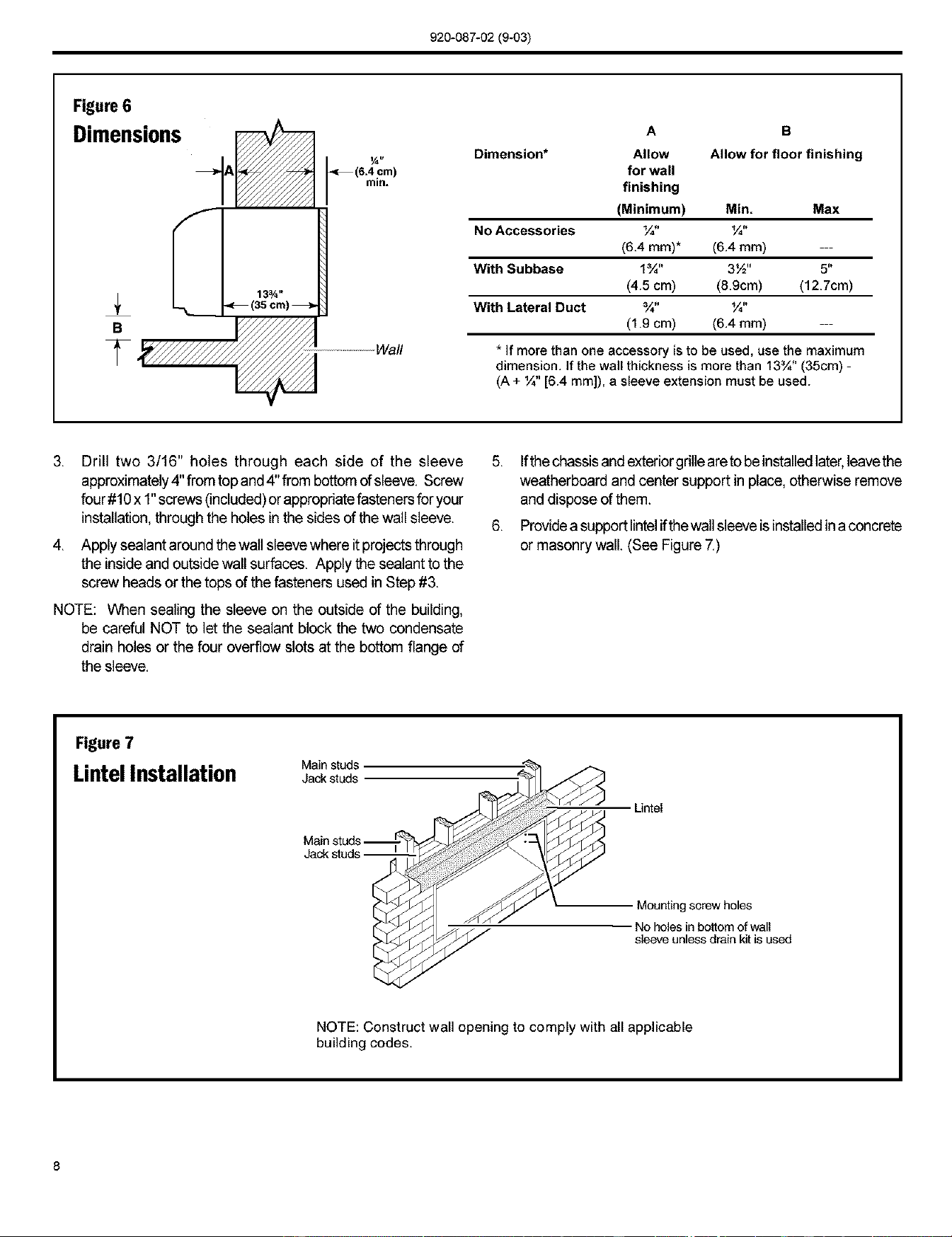
Figure 6
Dimensions
A
S
_ ...........Wall
'_7€/////_ _ 6.4 cm
in.
13¾ _
Dimension*
A B
Allow Allow for floor finishing
for wall
finishing
(Minimum) Min. Max
No Accessories ¼" ¼"
(6.4 ram)* (6.4 mm) ---
With Subbase 1¾" 3½" 5"
(4.5 cm) (8.9cm) (12.7cm)
With Lateral Duct ¾" ¼"
(1.9 cm) (6.4 mm) ---
* If mere than one accessory [sto be used, use the maximum
dimension. Ifthe wail thickness is more than 13¾" (35cm) -
(A + ¼" [6.4 mm]), a sleeve extension must be used.
,
Drill two 3/16" holes through each side of the sleeve
approximately4" from top and4" from bottom of sleeve. Screw
four #10x 1"screws (included)or appropriatefastenersfor your
installation, through the holes inthe sides of the wall sleeve.
4. Apply sealant around the wall sleevewhere itprojects through
the insideand outside wall surfaces. Apply the sealant to the
screw heads or the tops of the fasteners used in Step #3.
NOTE: When sealing the sleeve on the outside of the building,
be careful NOT to let the sealant block the two condensate
drain holes or the four overflow slots at the bottom flange of
the sleeve.
5. Ifthe chassisandexteriorgrilleareto beinstanedlater,leavethe
weatherboard and center support in place, otherwise remove
and dispose of them.
6. Providea supportlintelifthewall sleeve isinstalledina concrete
or masonry wall. (See Figure 7.)
Rgure 7
Main studs
LintelInstallation Jack studs
Jack stud
Untel
Mounting screw holes
No holes in bottom of wall
sleeve unless drain kit is used
NOTE: Construct wall opening to comply with all applicable
building codes.
8
920-087-02 (9-03)
Section II - DeepWall Installation(PXWE)
If the wail is thicker than allowed in the notes in Figure 6, a sheet
metal wall sleeve extension and flashing MUST be used.
Installation Instructions for the PXWE - 4" Wall Sleeve
Extension
The following points MUST be considered when installing a wall
sleeve extension:
Provision must be made to direct excess condensate from
the back of the wall sleeve into the extension then outside
the building or to a drainage system.
2. Air baffles must be mounted to properly direct airflow to and
from the condenser.
3. The wail sleeve extension design must allow for the proper
mounting of the grille.
4. Caulking is required at ansites where condensate or external
water could potentially infiltrate into the building.
6. Condensate notches and overflow slots must be kept clear
of sealant and gaskets so condensate can flow freely intothe
wall sleeve extension.
NOTE: Improperfabrication or installationof a wall sleeveextension
will impair PTAC performance.
Extension Installation
Secure the wall sleeveextension to the wail sleeve before installing
it in the wall. Refer to Figure 8 for a guide for fabrication of a
condensate drip panel. The panel MUST extend the full depth of
the wail sleeve and the wail sleeve extension.
Payparticular care in sealingand caulkingthe panelwhere itmakes
contact with the wall sleeve (see Figure 8). After installation in the
wall, secure with fasteners through the sides. Use a good grade
of silicone sealant around the sleeve extension. Seal all exposed
screw heads. When the installation is complete, the outside grille
should be attached to the wall sleeve extension.
5. Fabricate and install metal flashing in wall to serve as a drip
panel. Refer to drawing for more information.
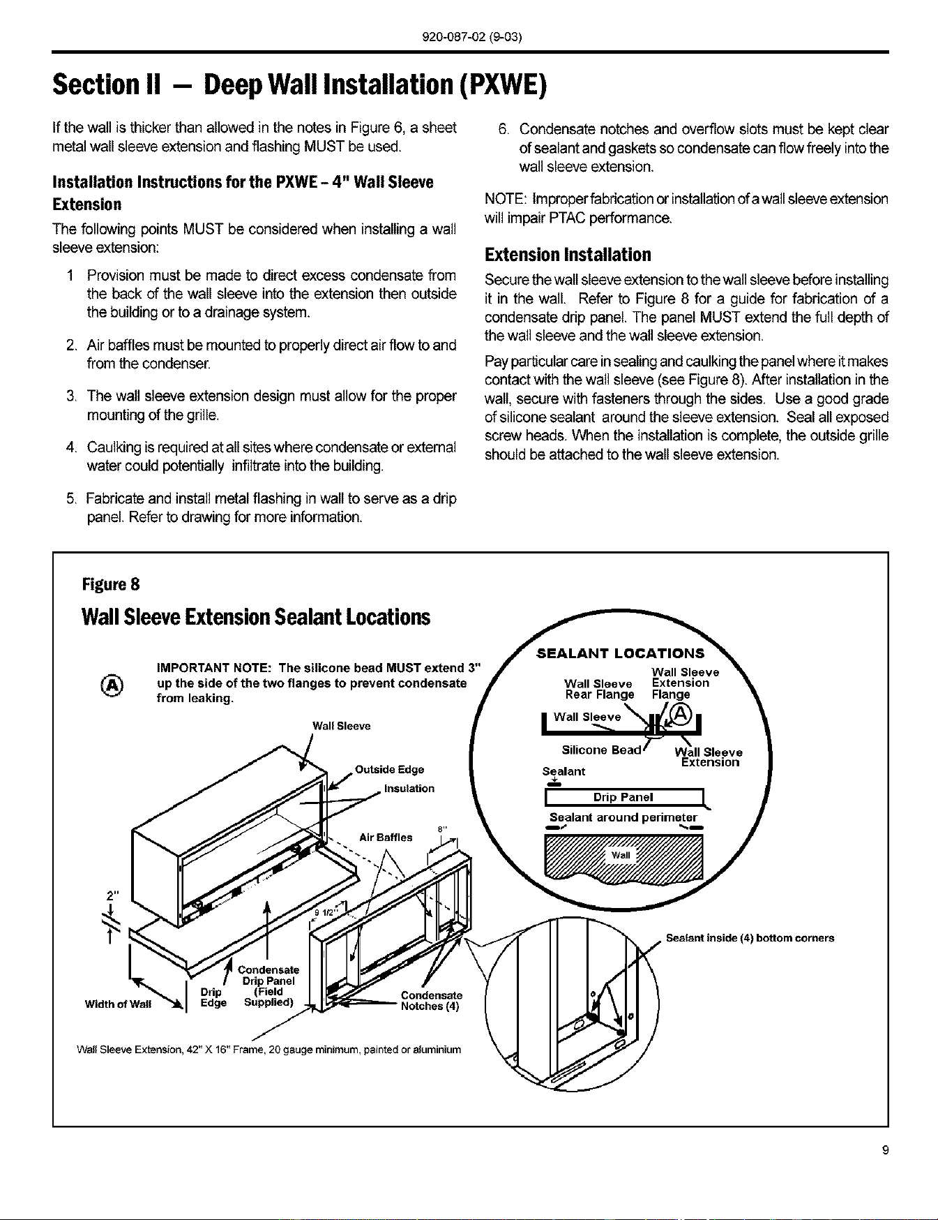
Figure8
Wall Sleeve ExtensionSealant Locations
®
IMPORTANT NOTE: The silicone bead MUST extend 3"
up the side of the two flanges to prevent condensate
from leaking.
Wall Sleeve
Outside Edge
Insulation
Wall Sleeve
Wall Sleeve Extension
Rear Flange Flange
| Wall SLoe %_j_) |
Silicone Bead T-_ "%'
Wall Sleeve
Extension
Sealant
I Drip Panel L
Sealant around perimeter
2 n
Sealant inside (4) bottom corners
Drip
Width of Wall Edge Notches (4)
Wall Sleeve Extension, 42" X 16" Frame, 20 gauge minimum, painted or aluminium
9
920-087-02(9-03)
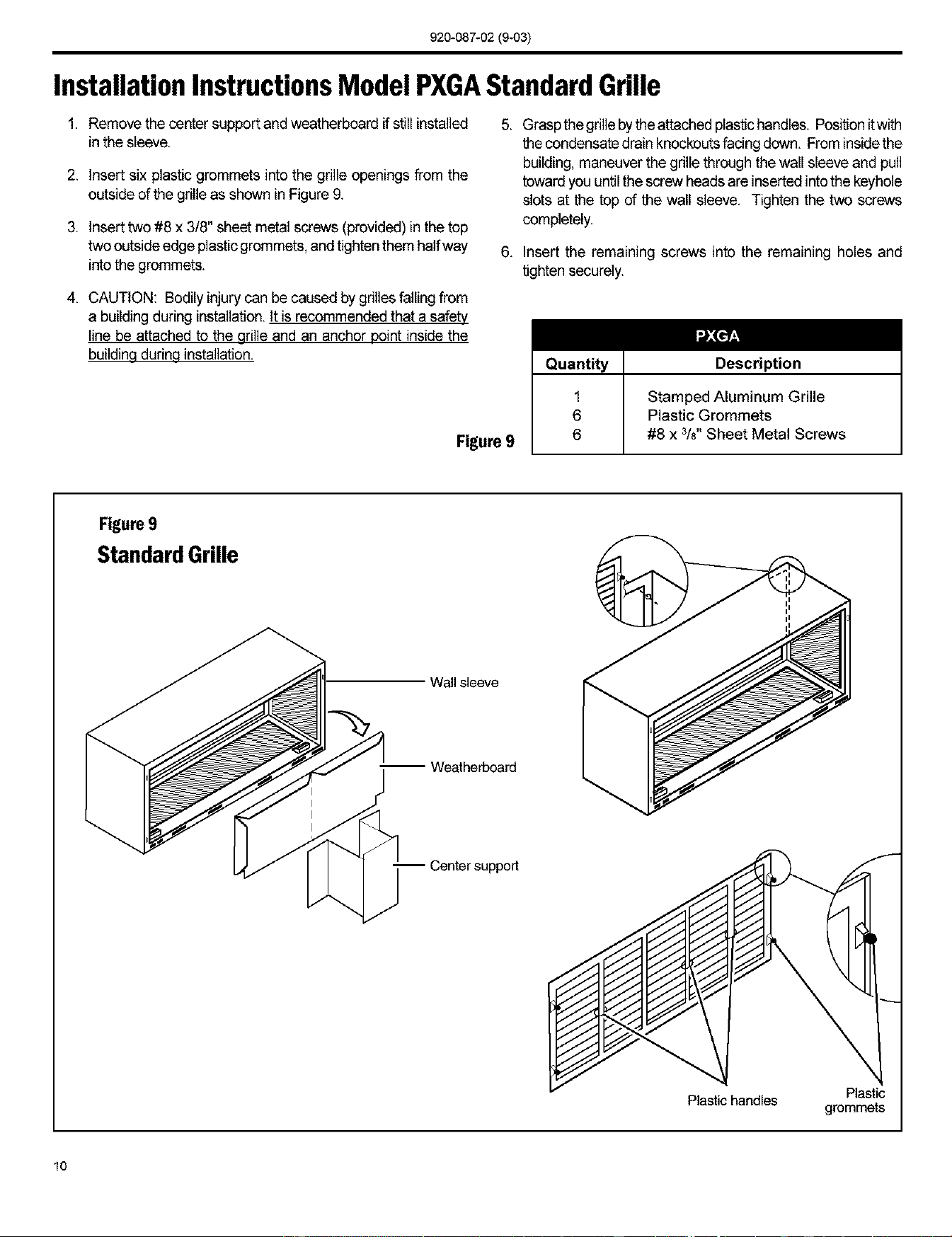
Installation InstructionsModel PXGAStandard Grille
1. Remove the center support and weatherboardifstininstalled
in the sleeve.
2. Insert six plastic grommets into the grille openings from the
outside of the grille as shown in Figure 9.
3. Insert two #8 x 3/8" sheet metal screws (provided) in the top
two outside edge plastic grommets, and tighten them halfway
into the grommets.
4. CAUTION: Bodily injury can be caused by grilles falling from
a building during installation. It is recommended that a safety
line be attached to the grille and an anchor point inside the
building durinq installation.
5. Grasp the grille bythe attached plastic handles. Positionit with
the condensate drain knockouts facing down. From insidethe
building, maneuver the grille through the wall sleeve and pull
toward you untilthe screw heads are inserted into the keyhole
slots at the top of the wall sleeve. Tighten the two screws
completely.
6. Insert the remaining screws into the remaining holes and
tighten securely.
Figure 9
Quantity Description
1 Stamped Aluminum Grille
6 Plastic Grommets
6 #8 x 3/8"Sheet Metal Screws
Figure 9
StandardGrille
Waft sleeve
-- Weatherboard
-- Center support
Plastic handles
\
\
Plastic
grommets
10
920-087-02(9-03)
A. Installation Checklist
[]
[]
[]
[]
[]
Inspect all components and accessories for damage
before and after installation.
[] Install the recommended Condensate Drain Kits for
complete condensate removal.
Remove the cardboard wall sleeve support and grille []
weatherboard.
Check for proper wall sleeve installation in accordance
with the wall sleeve installation instructions.
Check installation of the wall sleeve foam gasket.
Check for a subbase kit or other means of structural
support which is required for ALL installations projecting
more than 8" into room.
Ensure that the chassis is installed in a 16" high x42" wide
wall sleeve that is no deeper than
13 3/4". A baffle kit is required if the sleeve exceeds that
depth.
[] Ensure that drapes, bed, bedspread, furniture, etc. DO
NOT block either return or discharge air grilles.
[] Inspect the condenser air inlet and outlet for any
obstructions (shrubbery, etc,)
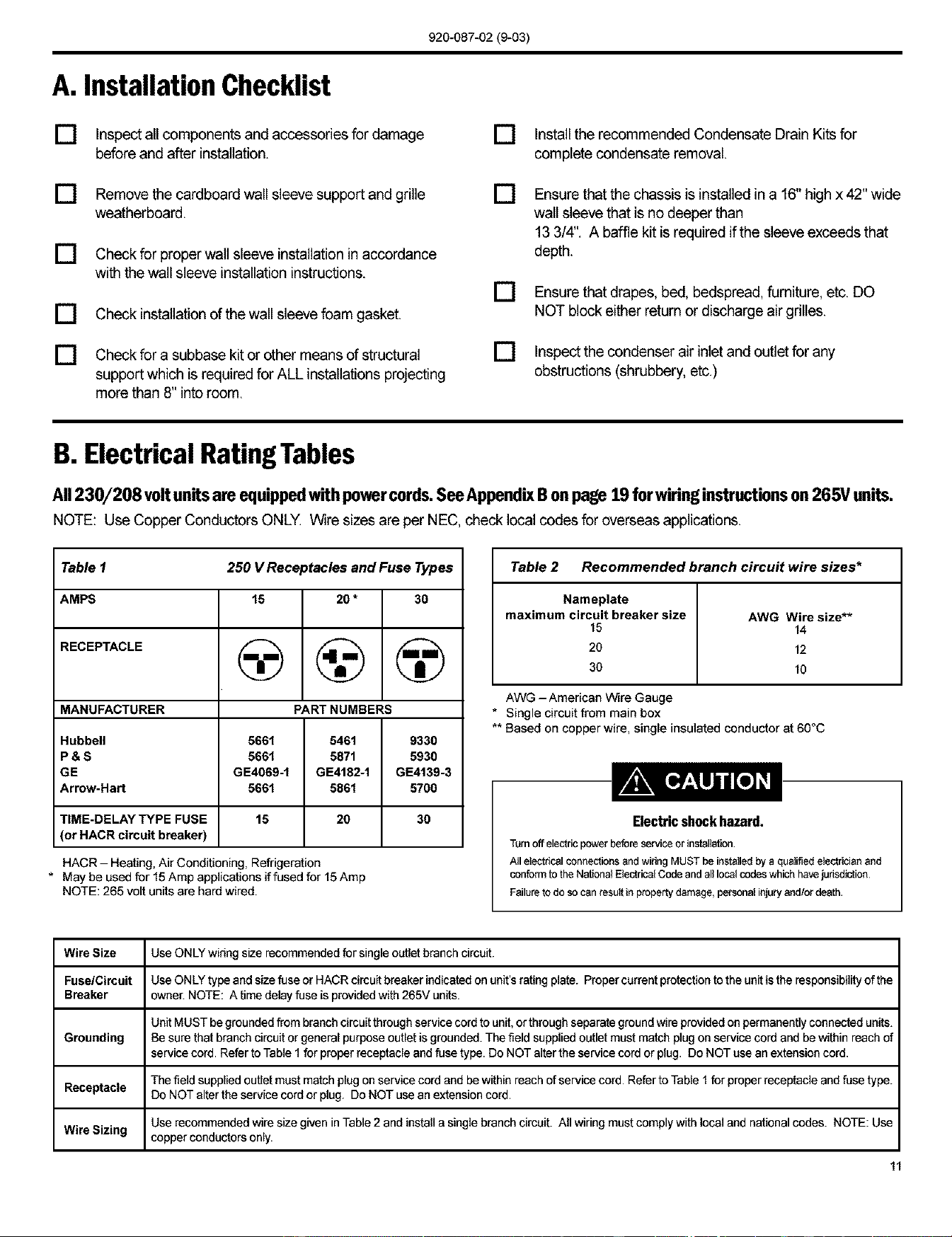
B. ElectricalRatingTables
All230/208 voltunitsare equippedwithpowercords.SeeAppendixB onpage 19 for wiringinstructionson 265V units.
NOTE: Use Copper Conductors ONLY. Wire sizes are per NEC, check local codes for overseas applications.
Table 1 250 V Receptacles and Fuse Types
AMPS 15 20 * 30
RECEPTACLE (_ (_ (_
MANUFACTURER PART NUMBERS
Hubbell 5661 5461 9330
P & S 5661 5871 5930
GE GE4069-1 GE4182-1 GE4139-3
Arrow-Hart 5661 5861 5700
TiME-DELAY TYPE FUSE 15 20 30
(or HACR circuit breaker)
HACR- Heating, Air Conditioning, Refrigeration
* May be used for 15 Amp applications if fused for 15 Amp
NOTE: 265 volt units are hard wired.
Table 2 Recommended branch circuit wire sizes*
Nameplate
maximum circuit breaker size AWG Wire size**
15 14
20 12
30 10
AWG -American Wire Gauge
* Single circuit from main box
** Based on copper wire, single insulated conductor at 60°C
Electric shock hazard.
Turnoff electricpowerbeforeserviceorinstallation
A_IelectricalconnectionsandwiringMUSTbe instaUedbya qualifiedelectricianand
confon'nto the NationalElectricalCodeandalllocalcodeswhich havejurisdiction
Failureto do socanrescttin propertydamage,personalinjuryand/ordeath.
Wire Size Use ONLY wiringsize recommendedfor single outlet branch circuit.
Fuse/Circuit Use ONLY type and size fuse or HACR circuit breaker indicated on unit's rating plate. Proper current protection to the unit is the responsibility of the
Breaker owner. NOTE: A time delay fuse is provided with 265V units.
Unit MUST be grounded from branch circuit through service cord to unit, or through separate ground wire providedon permanentlyconnected units.
Grounding Be sure that branch circuit or general purpose outlet is grounded. The field supplied outlet must match plugon service cord and be within reach of
service cord. Refer to Table I for proper receptacle and fuse type. Do NOT alter the service cord or plug. Do NOT use an extension cord.
The field supplied outlet must match plugon service cord and be within reach of service cord. Refer to Table 1 for proper receptacle and fuse type.
Receptacle Do NOT alter the service cord or plug. Do NOT use an extension cord.
Use recommended wire size given in Table 2 and install a single branch circuit. All wiring must comply with local and national codes. NOTE: Use
Wire Sizing copper conductors only.
11
920-087-02(9-03)
Section III - ChassisInstallation
* Check to be sure the wall sleeve, extension (if used), grille, and drain kit are installed properly before
chassis installation
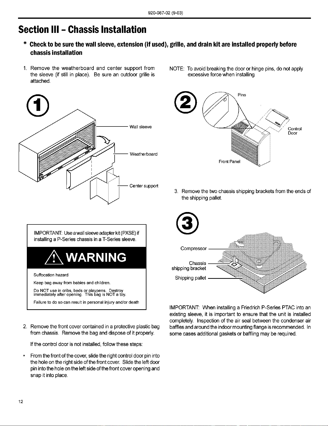
1. Remove the weatherboard and center support from
the sleeve (if still in place). Be sure an outdoor grille is
attached.
NOTE: To avoid breaking the door or hinge pins, do not apply
excessive force when installing
_ Pins
Wall sleeve / Control
Door
-- Weatherboard
Center support
Front Panel
3. Remove the two chassis shipping brackets from the ends of
the shipping pallet.
IMPORTANT:Useawa]]sleeveadapterkit(PXSE)if
installinga P-Series chassis in a T-Seriessleeve.
Suffocation hazard
Keep bag away from babies and children.
Do NOT use in cribs, beds or playpens. Destroy
immediately after opening. This oag is NOT a toy.
Failure to do so can result in personal injury end/or death
2. Remove the front cover contained ina protective plastic bag
from chassis. Remove the bag and dispose of it properly.
If the control door is not installed,follow these steps:
Fromthe front of the cover, slide the right control door pin into
the hole onthe right side of the front cover. Slidethe left door
pin into the hole on the leftside of the front cover opening and
snap it intoplace.
@
Compressor
Chassis
shipping bracket
Shipping pallet
IMPORTANT: When installinga Friedrich P-Series PTAC intoan
existing sleeve, it is important to ensure that the unit is installed
completely. Inspection of the air seal between the condenser air
baffles and aroundthe indoormountingflange isrecommended. In
some cases additional gaskets or baffling may be required.
12
920-087-02(9-03)
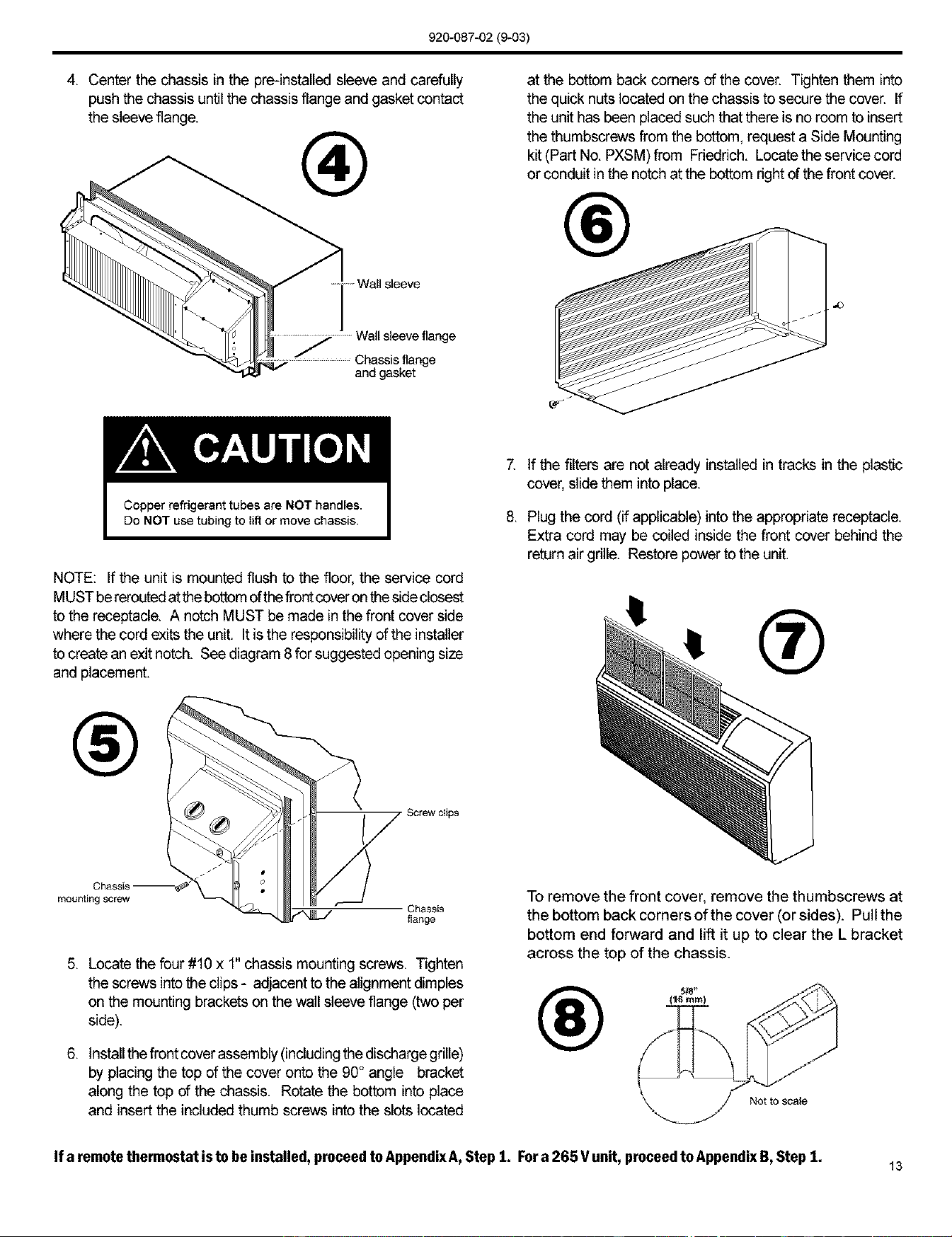
4. Center the chassis in the pre-instaned sleeve and carefully
push the chassis until the chassis flange and gasket contact
the sleeve flange.
®
....... Wall sleeve
Wallsleeveflange
Chassisflange
and gasket
at the bottom back corners of the cover. Tighten them into
the quick nuts located on the chassis to secure the cover. If
the unit has been placed such that there is no room to insert
the thumbscrews from the bottom, request a Side Mounting
kit (Part No. PXSM) from Friedrich. Locate the service cord
or conduit in the notch at the bottom right of the front cover.
®
NOTE: If the unit is mounted flush to the floor, the service cord
MUST bereroutedat the bottom of the frontcoveron the sideclosest
to the receptacle. A notch MUST be made in the front cover side
where the cord exits the unit. Itis the responsibility of the installer
to create an exit notch. See diagram 8 for suggested opening size
and placement.
®
mounting screw
Chassis
flange
5. Locate the four #10 x 1" chassis mounting screws. Tighten
the screws into the clips - adjacent to the alignment dimples
on the mounting brackets on the wall sleeve flange (two per
side).
6. lnstanthe frontcover assembly (including the dischargegrine)
by placing the top of the cover onto the 90° angle bracket
along the top of the chassis. Rotate the bottom into place
and insert the included thumb screws into the slots located
7. If the filters are not already installed in tracks in the plastic
cover, slide them into place.
8. Plug the cord (if applicable) into the appropriate receptacle.
Extra cord may be coiled inside the front cover behind the
return air grille. Restore power to the unit.
®
To remove the front cover, remove the thumbscrews at
the bottom back comers of the cover (or sides). Pull the
bottom end forward and lift it up to clear the L bracket
across the top of the chassis.
®
Not to scale
If a remotethermostat isto be installed,proceedtoAppendixA,Step 1. Fora 265 Vunit, proceedto AppendixB,Step 1. 13
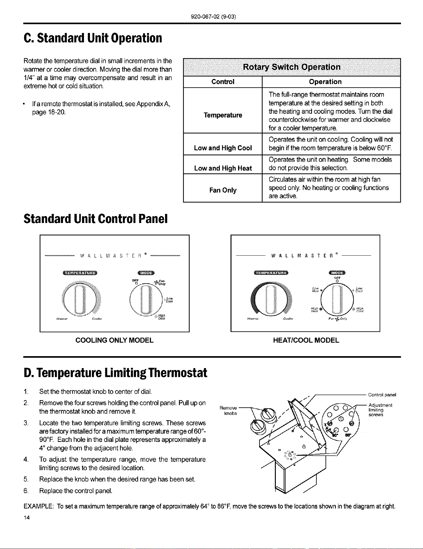
C.Standard Unit Operation
920-087-02 (9-03)
Rotate the temperature dial in small increments in the
warmer or cooler direction. Moving the dial more than
1/4" at a time may overcompensate and result in an
extreme hot or cold situation.
Ifa remotethermostat is installed,see Appendix A,
page 18-20.
Control Operation
The full-range thermostat maintains room
temperature at the desired setting in both
Temperature the heating and cooling modes. Turn the dial
counterclockwise for warmer and clockwise
for a cooler temperature.
Operates the unit on cooling. Cooling will not
Low and High Cool begin ifthe room temperature is below 60°F.
Operates the unit on heating. Some models
Low and High Heat do not provide this selection.
Circulates air within the room at high fan
Fan Only speed only. No heating or cooling functions
are active.
Standard Unit ControlPanel
_#ALLMAST E R ®
COOLING ONLY MODEL HEAT/COOL MODEL
D.TemperatureLimitingThermostat
1,
2.
,
4,
5,
6,
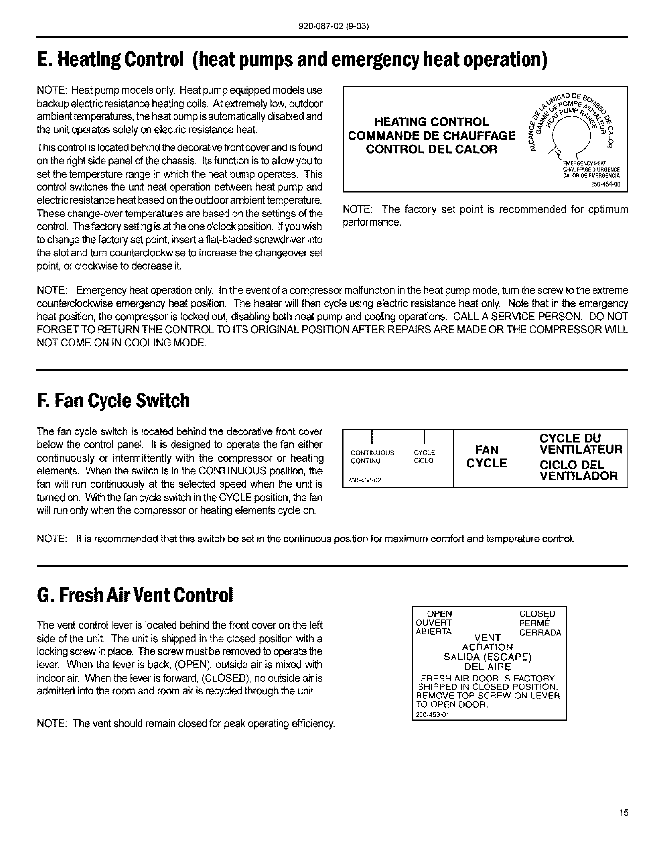
Set the thermostat knob to center of dial.
Remove the four screws holding the control panel. Pull up on
the thermostat knob and remove it.
Locate the two temperature limiting screws. These screws
arefactory installedfor a maximumtemperature rangeof 60°-
90°E Each hole in the dial plate represents approximately a
4° change from the adjacent hole.
To adjust the temperature range, move the temperature
limiting screws to the desired location.
Replace the knob when the desired range has been set.
Replace the control panel.
Remo_
knobs
Control panel
limiting
SCreWS
EXAMPLE: To set a maximum temperature range of approximately 64° to 86°F, move the screws to the locations shown in the diagram at right,
14
920-087-02 (9-03)
E. HeatingControl (heat pumpsand emergencyheat operation)
NOTE: Heat pump models only. Heat pump equipped models use
backup electric resistance heating coils. At extremely low,outdoor
ambient temperatures, the heat pump is automatically disabled and
the unit operates solely on electric resistance heat.
This control islocated behindthe decorativefrontcover and isfound
on the right side panel of the chassis. Itsfunction is to allow you to
set the temperature range inwhich the heat pump operates. This
control switches the unit heat operation between heat pump and
electric resistanceheat based on the outdoor ambient temperature.
These change-over temperatures are based on the settings of the
control. The factory setting is at the one o'clock position. Ifyou wish
to change the factory set point, insert a flat-bladed screwdriver into
the slot and turn counterclockwise to increase the changeover set
point, or clockwise to decrease it.
HEATING CONTROL
COMMANDE DE CHAUFFAGE
CONTROL DEL CALOR
\OAD O_"
EMERGeNCy HEAT
CHAUFFAG£o URGENCE
CALOR D_ [ME_G_NCIA
250454-00
NOTE: The factory set point is recommended for optimum
performance.
NOTE: Emergency heat operation only. In the event of a compressor malfunction in the heat pump mode, turn the screw to the extreme
counterclockwise emergency heat position. The heater will then cycle using electric resistance heat only. Note that in the emergency
heat position, the compressor is locked out, disabling both heat pump and cooling operations. CALL A SERVICE PERSON. DO NOT
FORGET TO RETURN THE CONTROL TO ITS ORIGINAL POSITION AFTER REPAIRS ARE MADE OR THE COMPRESSOR WILL
NOT COME ON IN COOLING MODE.
F.FanCycleSwitch
The fan cycle switch is located behind the decorative front cover
below the control panel. It is designed to operate the fan either
continuously or intermittently with the compressor or heating
elements. When the switch is in the CONTINUOUS position,the
fan will run continuously at the selected speed when the unit is
turned on, With the fan cycle switch in the CYCLE position, the fan
will run only when the compressor or heating elements cycle on.
I I
CONTINUOUS CYCLE
GONTINU CICLO
250-458-02
CYCLE DU I
FAN VENTILATEUR I
CYCLE CICLO DEL
VENTILADOR
NOTE: It is recommended that this switch be set in the continuous position for maximum comfort and temperature control.
G. FreshAirVentControl
The vent control lever is located behind the front cover on the left
side of the unit. The unit is shipped in the closed position with a
locking screw in place. The screw must be removedto operate the
lever. When the lever is back, (OPEN), outside air is mixed with
indoor air. When the lever is forward, (CLOSED), no outside air is
admitted into the room and room air is recycled through the unit.
NOTE: The vent should remain closed for peak operating efficiency.
OPEN CLOSED
OUVERT FERME
ABIERTA CERRADA
VENT
AERATION
SALIDA (ESCAPE)
DEL AIRE
FRESH AIR DOOR IS FACTORY
SHIPPED IN CLOSED POSITION.
REMOVE TOP SCREW ON LEVER
TO OPEN DOOR.
250_453_01
15
920-087-02 (9-03)
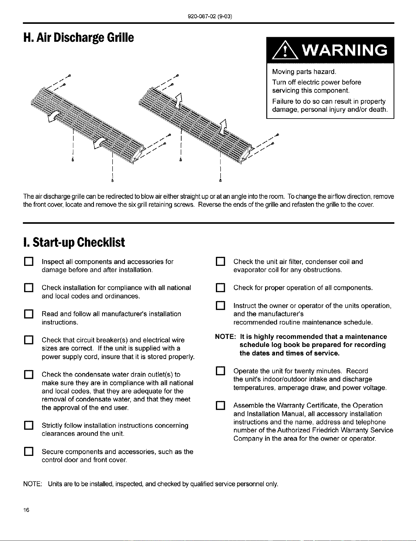
H.Air DischargeGrille
Moving parts hazard
Turn oft electric power before
servicing this component.
Failure to do so can result in property
damage, personal injury and/or death.
I
I
I
®
The air discharge grillecan be redirectedto blow air either straight up or at an angle into the room. To change the airflow direction, remove
the front cover, locate and remove the six grill retaining screws. Reverse the ends of the grille and refasten the grille to the cover.
I. Start-up Checklist
[] Inspect all components and accessories for
damage before and after installation.
[] Check installation for compliance with all national
and local codes and ordinances.
[] Read and follow all manufacturer's installation
instructions.
[] Check that circuit breaker(s) and electrical wire
sizes are correct. If the unit is supplied with a
power supply cord, insure that it is stored properly.
[] Check the condensate water drain outlet(s) to
make sure they are in compliance with all national
and local codes, that they are adequate for the
removal of condensate water, and that they meet
the approval of the end user.
[] Strictly follow installation instructions concerning
clearances around the unit.
] Secure components and accessories, such as the
control door and front cover.
[] Check the unit air filter, condenser coil and
evaporator coil for any obstructions
[] Check for proper operation of all components.
[] Instruct the owner or operator of the units operation,
and the manufacturer's
recommended routine maintenance schedule.
NOTE: It is highly recommended that a maintenance
schedule log book be prepared for recording
the dates and times of service.
[] Operatethe unit for twenty minutes Record
the unit's indoor/outdoor intake and discharge
temperatures, amperage draw, and power voltage.
[] Assemble the Warranty Certificate, the Operation
and Installation Manual, all accessory installation
instructions and the name, address and telephone
number of the Authorized Friedrich Warranty Service
Company in the area for the owner or operator.
NOTE: Units are to be installed, inspected, and checked by qualified service personnelonly.
16
920-087-02(9-03)
AppendixA: RemoteThermostatUnit Installation
RemoteThermostatSelection& WiringGuidelinesfor
PackagedTerminalAirConditioners
Follow the instructions and recommendations of the thermostat
manufacturer for installation and wiring. Do not use a conventional
heat pump thermostat with emergency electric heat selection for
our heat pump units. Our units make an automatic decision about
turning on electric heat if the heating demand cannot be met by the
heat pump due to low outdoor temperatures.
Manual Changeover Thermostat
For Heat Pump equipped units: A single stage, heat/cool
thermostat with aterminalfor a reversingvalve operation isrequired.
Terminal "B" should be continuously energized in the heat mode
and terminal "G" should be energized whenever there is a call for
heating or cooling. Typically, a heat/cool thermostat designed for
use with electric heat systems will meet the above requirements.
NOTE: This unit is designed for use with a single stage thermostat only. Improper application of the thermostat may result in property
damage, personal injury or death.
Honeywell Thermostat Terminal Designation:
TERMINAL LETTER OPERATION CONTACT MADE
Y Cooling During call for cooling.
W Heating During call for heating.
G Fan Continuous if the slider is inthe "Fan" position,otherwise, intermittent.
C Common Terminal For thermostats requiring a common terminal
R 24 V to the thermostat Directly from the transformer
B (Heat Pump units Only) Reversing Valve Made continuously during call for heating.
For Non-Heat Pump equipped units: A single stage cooling and heating thermostat is required. Terminal "G" should be
energized whenever a call for heating or cooling is made. Typically a heat/cool thermostat designed for use with electric heat
systems will meet this requirement.
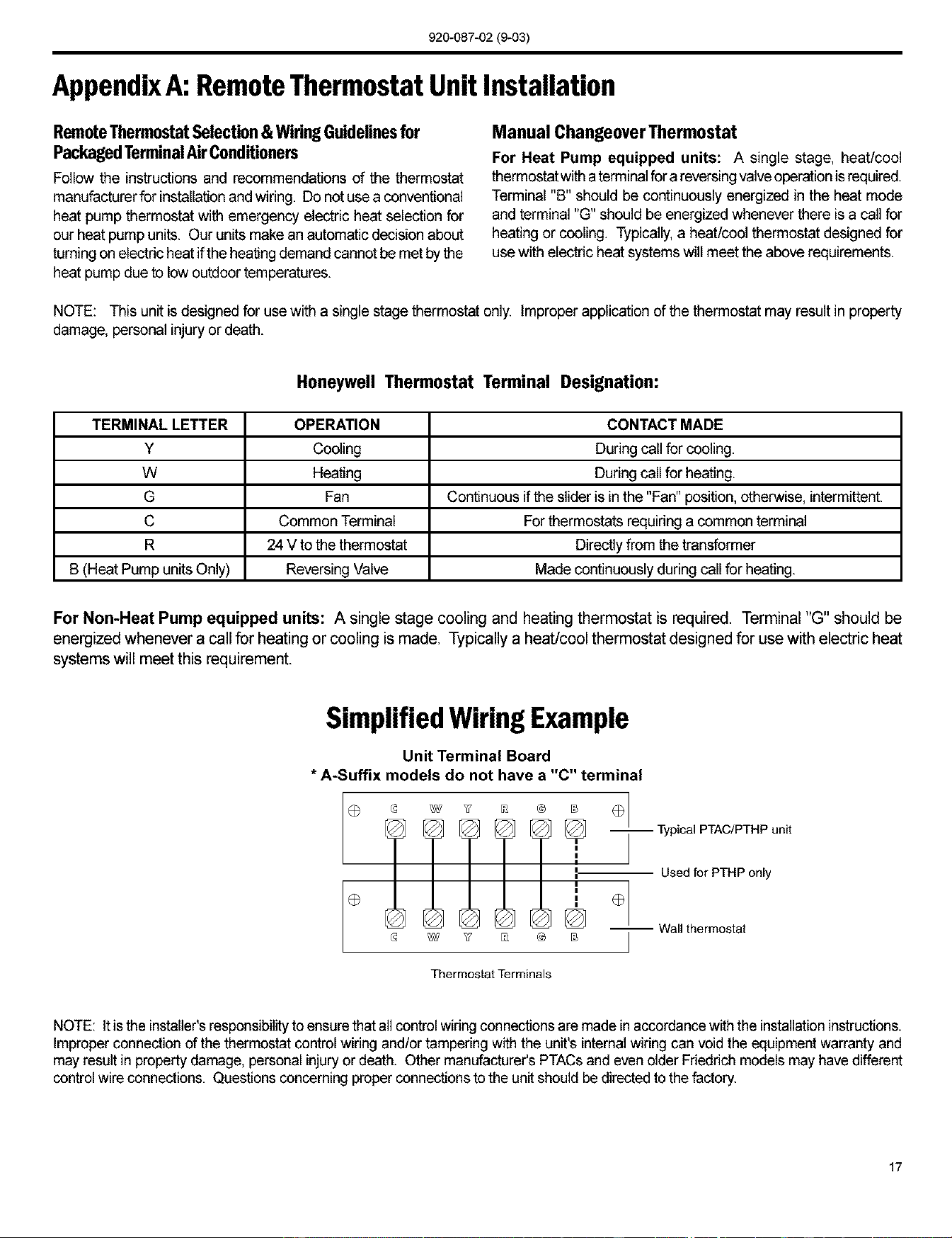
SimplifiedWiringExample
Unit Terminal Board
* A-Suffix models do not have a "C" terminal
I
0 @ _ v _ ® B 01
--T.plca,PTAO,PT.P..lti
[_ -- Wall thermostat
Thermostat Terminals
NOTE: It isthe installer'sresponsibilityto ensurethat all control wiring connectionsare made inaccordance with the installationinstructions.
Improper connection of the thermostat control wiring and/or tampering with the unit's internalwiring can void the equipment warranty and
may result in property damage, personal injury or death. Other manufacturer's PTACsand even older Fdedrich models may have different
control wire connections. Questions concerning proper connectionsto the unit should be directedto the factory.
17
920-087-02(9-03)
AppendixA(continued)
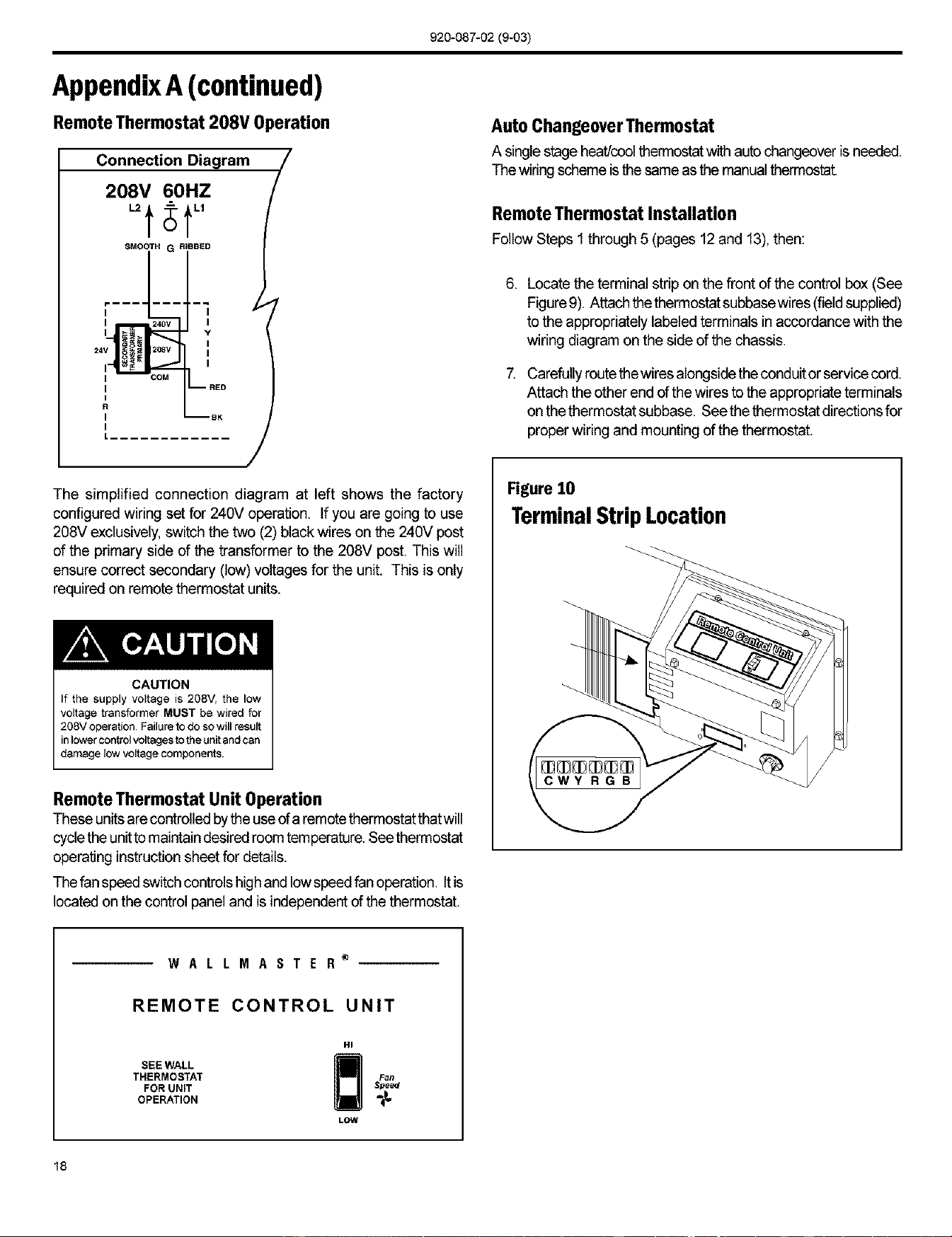
Remote Thermostat 208V Operation
Connection208V60HZDiagram/
-t;t
SMOOTHG RIBBED
i z
I
I
I
COM
The simplified connection diagram at left shows the factory
configured wiring set for 240V operation. If you are going to use
208V exclusively, switch the two (2) black wires on the 240V post
of the primary side of the transformer to the 208V post. This will
ensure correct secondary (low)voltages for the unit. This is only
required on remote thermostat units.
CAUTION
If the supply voltage is 208V, the low
voltage transformer MUST be wired for
208V operation Failure to do so will result
in lower contro_ voltages to the unit and can
damage _ow voltage components
Remote Thermostat Unit Operation
Theseunitsare controlledby the use of a remotethermostat thatwill
cycle the unitto maintaindesired room temperature.Seethermostat
operating instruction sheet for details.
The fan speed switch controlshighand low speed fan operation. Itis
located on the control panel and is independent of the thermostat.
Auto Changeover Thermostat
A singlestage heat/coolthermostatwith auto changeoveris needed.
The wiring scheme is the same as the manualthermostat.
Remote Thermostat Installation
Follow Steps 1through 5 (pages 12and 13), then:
6. Locate the terminal strip on the front of the control box (See
Figure9). Attach thethermostat subbasewires(field supplied)
to the appropriately labeled terminals in accordance with the
wiring diagram on the side of the chassis.
7. Carefullyroute the wiresalongside the conduitor service cord.
Attach the other end of the wires to the appropriate terminals
on the thermostat subbase. Seethe thermostat directions for
proper wiring and mounting ofthe thermostat.
Figure 10
TerminalStripLocation
WALLMASTER _
REMOTE CONTROL UNIT
SEE WALL
THERMOSTAT
FOR UNIT
OPERATION
HI
Fan
Speed
-t-
LOW
18
920-087-02(9-03)
AppendixB: ElectricalWiringfor 265 Volt Models
NOTE: It is recommended that the PXSB subbase assembly, the PXCJ conduit kit and the PXDS disconnect switch be installed on all
hardwired units. If installing a flush-floor mounted unit, make provisions for allthe linevoltage power leads and conduit to be removed for
ease of maintenance and service to the chassis.
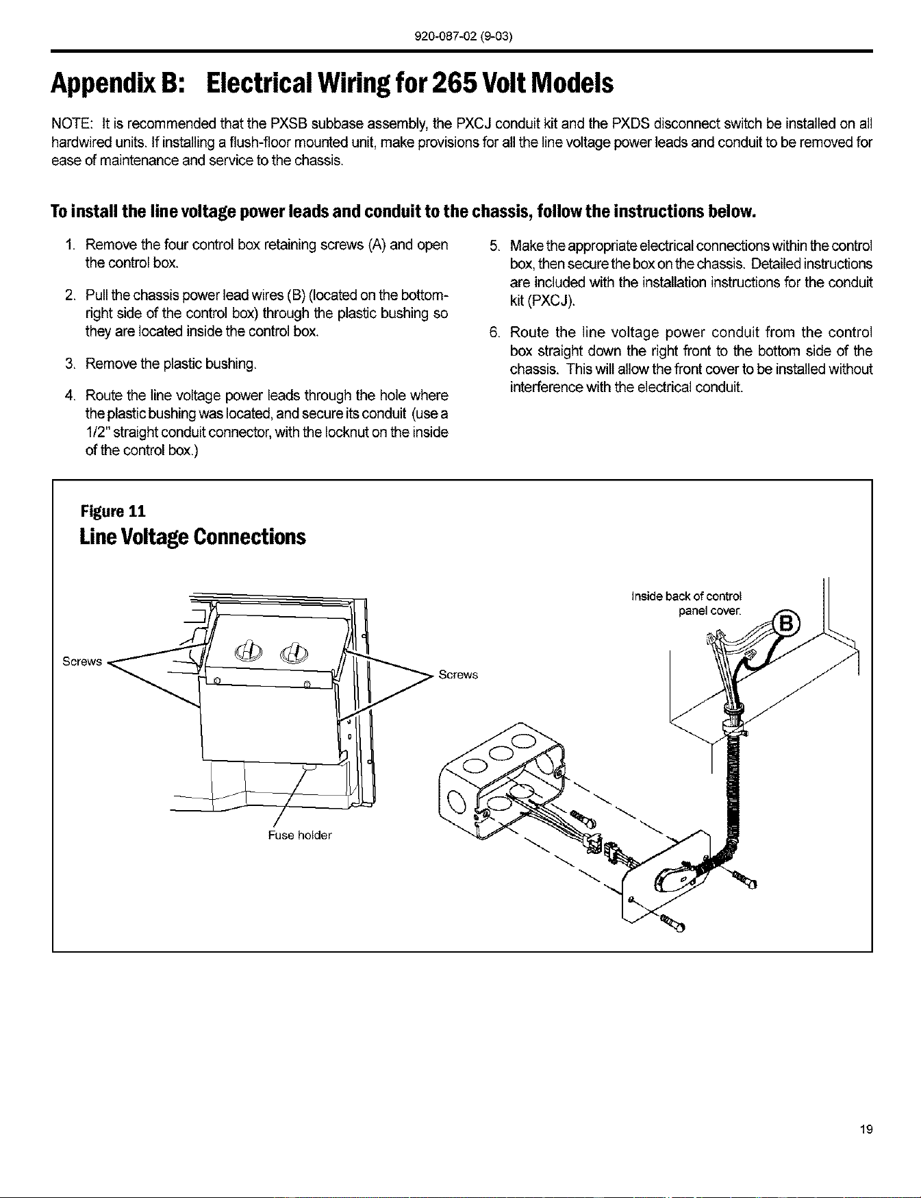
Toinstall the line voltage power leads and conduit to the chassis, follow the instructions below.
1. Remove the four control box retaining screws (A) and open
the control box.
2. Punthe chassis power lead wires (B) (locatedon the bottom-
right side of the control box) through the plastic bushing so
they are located inside the control box.
3. Remove the plastic bushing.
4. Route the line voltage power leads through the hole where
the plastic bushing was located, and secure itsconduit (use a
1/2" straightconduit connector,with the Iocknut on the inside
of the control box.)
5. Makethe appropriate electrical connections within the control
box,then secure the box onthe chassis. Detailed instructions
are included with the installation instructions for the conduit
kit (PXCJ).
6. Route the line voltage power conduit from the control
box straight down the right front to the bottom side of the
chassis. This will allow the front cover to be installedwithout
interference with the electrical conduit.
Figure 11
LineVoltageConnections
Fuse holder
SCOWS
Inside back of co_rol
panelcove_
19
920-087-02(9-03)
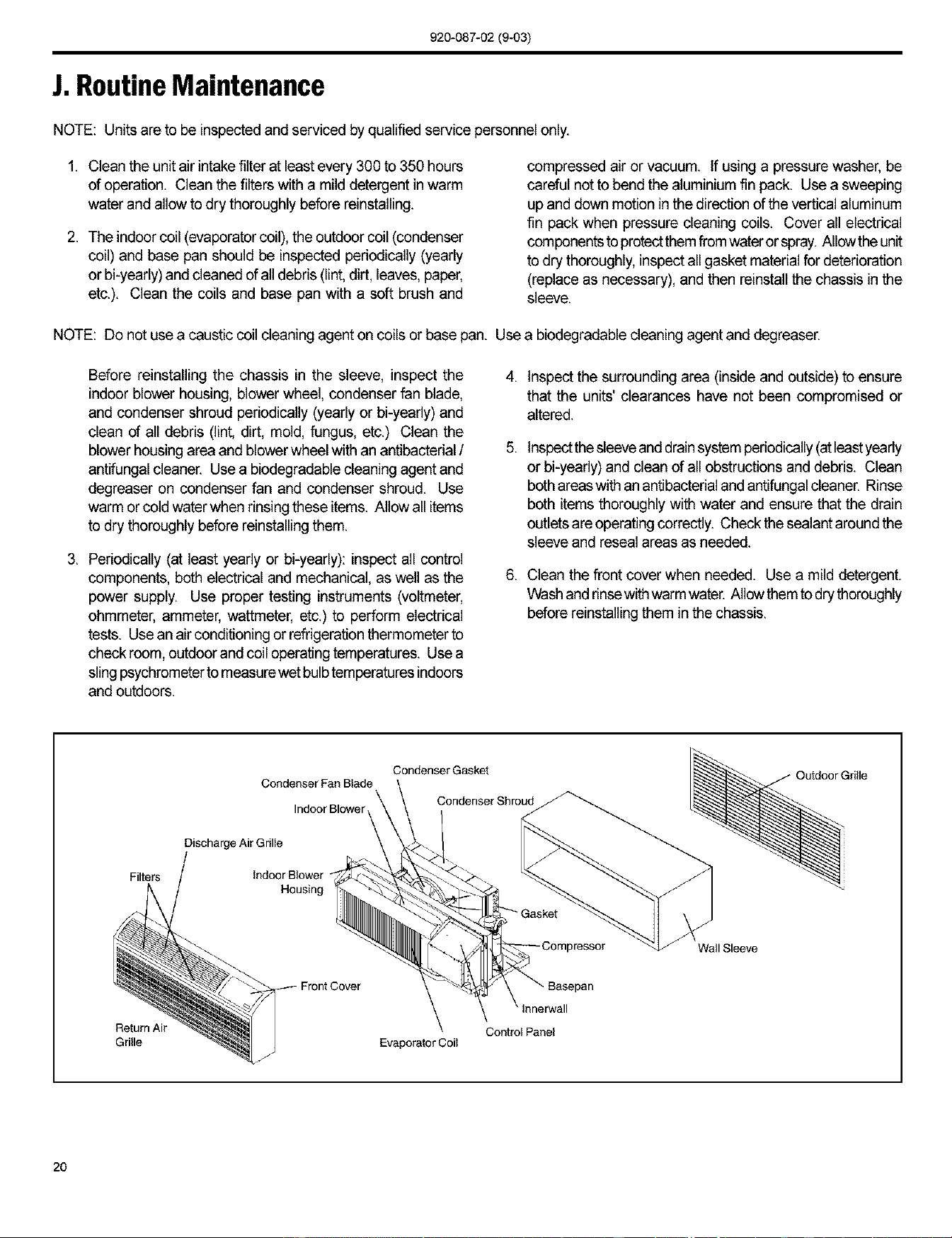
J.RoutineMaintenance
NOTE: Units are to be inspected and serviced by qualified service personnel only.
1. Clean the unit air intakefilter at leastevery 300 to 350 hours
of operation. Clean the filters with a mild detergent in warm
water and allow to dry thoroughly before reinstalling.
2. The indoor coil (evaporatorcoil), the outdoor coil (condenser
coil) and base pan should be inspectedperiodically (yearly
or bi-yearly) and cleaned of all debris (lint, dirt, leaves, paper,
etc.). Clean the coils and base pan with a soft brush and
compressed air or vacuum. If using a pressure washer, be
careful not to bend the aluminium fin pack. Use a sweeping
up and down motion in the direction of the vertical aluminum
fin pack when pressure cleaning coils. Cover all electrical
componentsto protectthem fromwateror spray. Allow the unit
to dry thoroughly, inspect allgasket materialfor deterioration
(replace as necessary), and then reinstall the chassis in the
sleeve.
NOTE: Do not use a caustic coil cleaning agent on coils or base pan. Use a biodegradable cleaning agent and degreaser.
Before reinstalling the chassis in the sleeve, inspect the
indoorblower housing, blower wheel, condenser fan blade,
and condenser shroud periodically (yearly or bi-yeafly) and
clean of all debris (lint, dirt, mold, fungus, etc.) Clean the
blower housing area and blower wheel with an antibacterial /
antifungal cleaner. Use a biodegradable cleaning agent and
degreaser on condenser fan and condenser shroud. Use
warm or cold water when rinsing these items.Allow all items
to dry thoroughly before reinstallingthem.
3. Periodically (at leastyearly or bi-yearly): inspectall control
components, both electrical and mechanical, as well as the
power supply. Use proper testing instruments(voltmeter,
ohmmeter, ammeter, wattmeter, etc.) to perform electrical
tests. Usean air conditioning or refrigeration thermometer to
check room, outdoor and coil operating temperatures. Use a
sling psychrometerto measurewet bulbtemperatures indoors
and outdoors.
4,
,
6,
Inspect the surrounding area (inside and outside) to ensure
that the units' clearances have not been compromised or
altered.
Inspectthe sleeveanddrainsystem periodically(at leastyearly
or bi-yearly) and dean of all obstructions and debris. Clean
both areaswith an antibacterial and antifungalcleaner. Rinse
both itemsthoroughly with water and ensure that the drain
outlets are operating correctly. Check the sealant aroundthe
sleeve and reseal areas as needed.
Clean the front cover when needed. Use a mild detergent.
Washand rinsewith warmwater. Allow themto dry thoroughly
before reinstallingthem in the chassis.
Filters
Return Air
Grille
CondenserFanBlade
\
DischargeAir Grille IndoorBlower_
Condenser Gasket
Condenser Shroud
8asepan
Control Panel
Evaporator Coil
Wall Sleeve
2O
920-087-02(9-03)
K. BasicTroubleshootingTechniques
Beingfamiliarwith the sequence of operation on Standard Controlled Operating Units or the operation of the RemoteThermostat Controlled
Units is important, The following questions and answers may help to identify performance problems,
EnvironmentalEffects- CoolingMode
Is unit sized to room size area and heat load demand?
RoomWidthx Lengthx 3.5 (x-factor)equal a "guesstimate" ofthe
numberofBTU'srequiredfor the area. The numberofpeopleinthe
room, number of electrical devices, solar gains, etc. are allvariable
items thatcan affect propersizingof the unit. Friedrichrecommends
that you consult with an applications engineer for proper sizing.
Is the outdoor temperature 60°F or below?
The unit is designed for outdoor temperatures above 60°E
Is the indoor temperature 80°F or above?
Ambient indoor temperatures of 80°F or above will take a longer
period of run time to cool down the area. Long run times may
indicate that the unit is undersized.
Is indoor humidity high?
This condition will cause the unit to operate longer to remove
humidity before noticing any cooling effect.
Hasthe heat load been increased by additional devices such
as computer equipment, or hasthe room area been increased
where the unit is located?
If conditions have changed, the unit may not be able to cool and
condition as effectively as previously planned.
Environmental Effects - Heating Mode
Is unit properly sized to room area and heat load demand?
Multiplying the Width x Length x 3.5 ("x-factor") provides a
"guesstimate" of the number of BTU's required for the area. The
number of people inthe room, number of electrical devices, solar
gains,etc. are all variable itemsthat can affect propersizingof the
unit. Ffieddchrecommends that you consult with an applications
engineer for proper sizing.
Is the outdoortemperature 70oForabove?- The unit is designed
for outdoor temperatures below 70°E
Is the indoor temperature 60°F or below? Ambient indoor
temperatures of 6O°F or below will take a longer period of run
time to heat the area. Long run times may indicate that the unit is
undersized.
Hasthe room area been increased where the unit is located?
If the area where the unit is located has been increased, the unit
may not provideadequateheat.
Insufficient Maintenance and Inspection
Installationerrorsare the most common cause of poorperformance.
Pleasefollow installationinstructionscarefully.Ifotherproblemsexist,
see Maintenance and InspectionTroubleshooting Guide below.
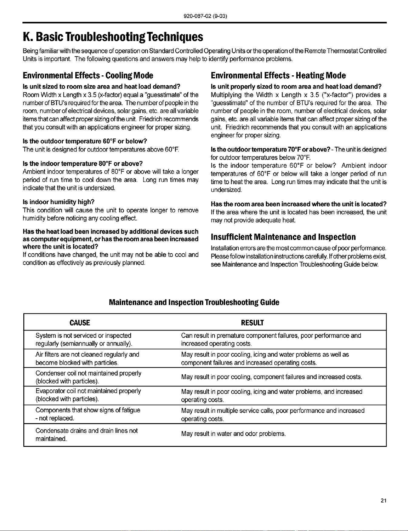
Maintenance and Inspection Troubleshooting Guide
CAUSE RESULT
System isnot serviced or inspected Can result inpremature component failures, poor performance and
regularly (semiannually or annually), increased operating costs.
Air filters are not cleaned regularly and May result in poor cooling, icing and water problems as well as
become blockedwith particles, component failures and increased operating costs.
Condenser coil not maintained properly May result in poor cooling, component failures and increased costs.
(blocked with particles).
Evaporator coil not maintained properly May result in poor cooling, icing and water problems, and increased
(blocked with particles), operating costs.
Components that show signs offatigue May result in multiple service calls, poor performance and increased
- not replaced, operating costs.
Condensate drains and drain lines not May result in water and odor problems.
maintained.
21
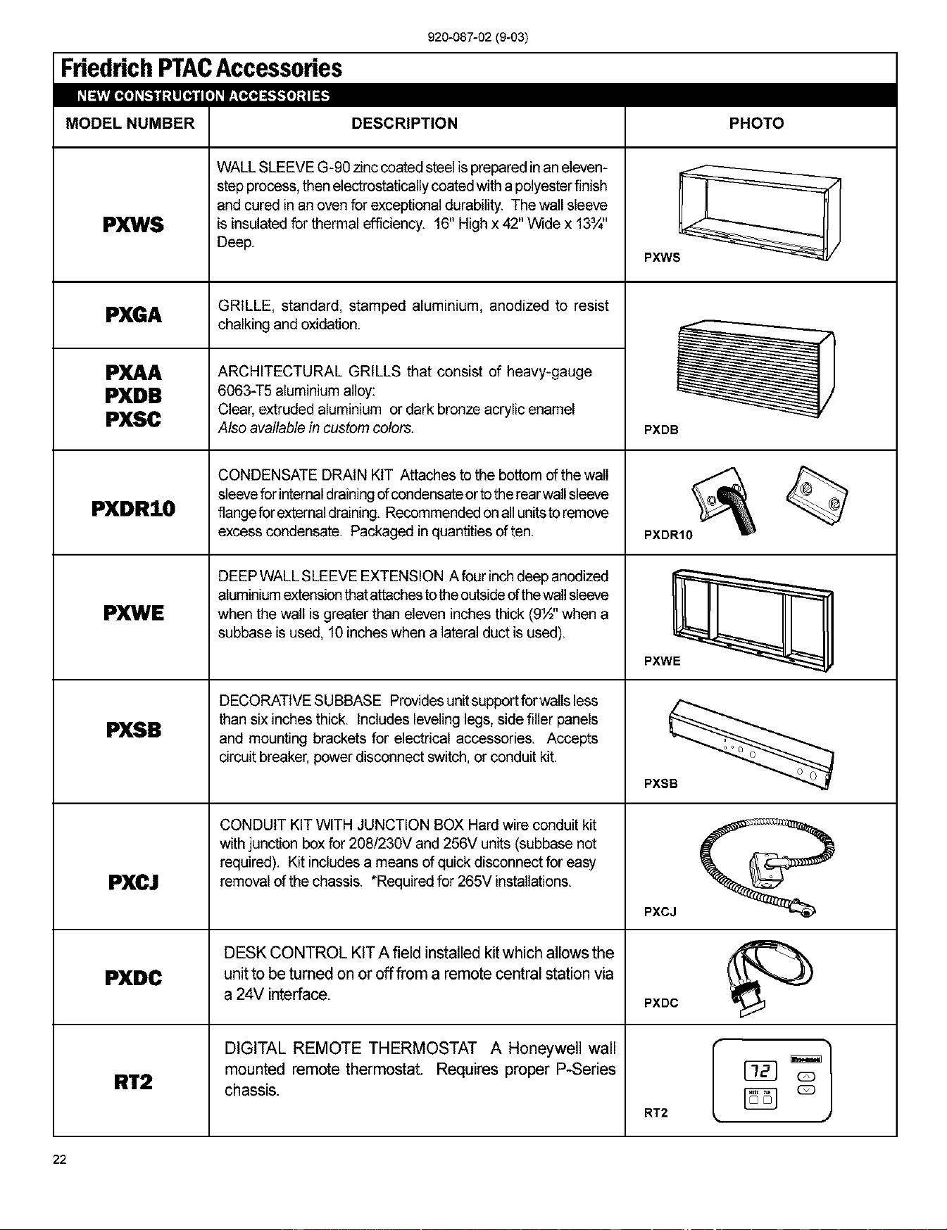
FriedrichPTACAccessories
920-087-02 (9-03)
MODELNUMBER
PXWS
PXGA
PXAA
PXDB
PXSC
PXDR10
PXWE
PXSB
PXCJ
PXDC
DESCRIPTION
WALL SLEEVE G-90 zinc coated steelis prepared in aneleven-
step process, then electrostaticanycoated witha polyester finish
and cured in an oven for exceptional durability. The wall sleeve
is insulated for thermal efficiency. 16" High x 42" Wide x 13¾"
Deep.
GRILLE, standard, stamped aluminium, anodized to resist
chalking and oxidation.
ARCHITECTURAL GRILLS that consist of heavy-gauge
6063-i5 aluminium alloy:
Clear, extruded aluminium or dark bronze acrylic enamel
Also available in custom colors.
CONDENSATE DRAIN KIT Attaches to the bottom of the wall
sleevefor internaldrainingofcondensate orto the rearwall sleeve
fiangefor externaldraining. Recommendedon allunitsto remove
excess condensate. Packaged in quantities often.
DEEP WALL SLEEVE EXTENSION A four inch deep anodized
aluminiumextensionthatattachesto the outsideof thewall sleeve
when the wall is greater than eleven inches thick (9½" when a
subbase is used, 10 inches when a lateral duct is used).
DECORATIVE SUBBASE Providesunit supportfor wansless
than six inches thick. Includes leveling legs, side filler panels
and mounting brackets for electrical accessories. Accepts
circuit breaker, power disconnect switch, or conduit kit.
CONDUIT KIT WITH JUNCTION BOX Hard wire conduit kit
with junction box for 208/230V and 256V units (subbase not
required). Kit includes a means of quick disconnect for easy
removal of the chassis. *Required for 265V installations.
DESK CONTROL KIT A field installed kit which allows the
unit to be turned on or off from a remote central station via
a 24V interface.
PHOTO
PXWS_ /
PXDB
PXDR1O
PXCJ
PXDC
RT2
DIGITAL REMOTE THERMOSTAT A Honeywell wall
mounted remote thermostat. Requires proper P-Series
chassis.
RT2
22
920-087-02(9-03)
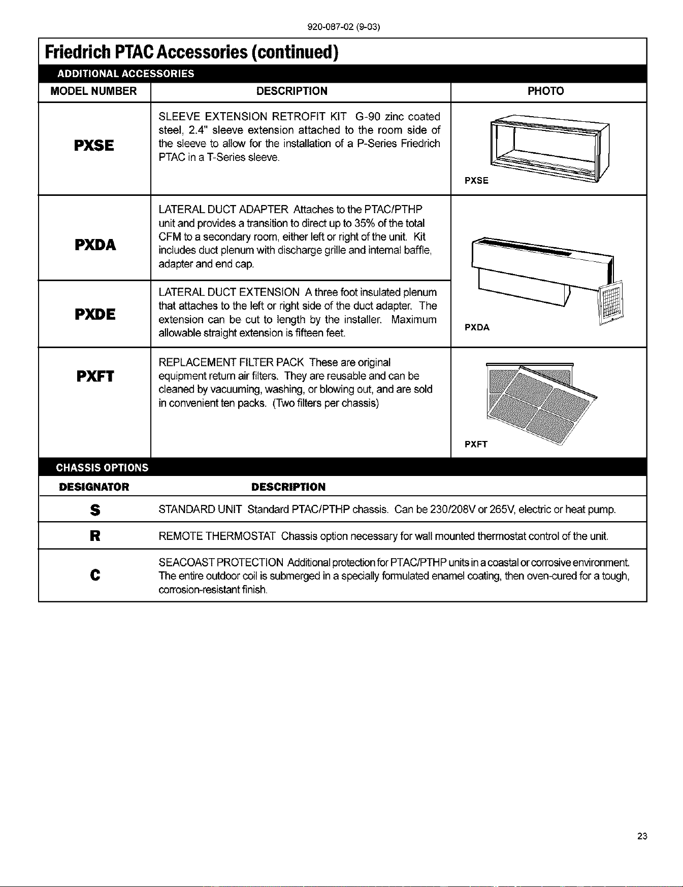
FriedrichPTACAccessories (continued)
MODEL NUMBER
PXSE
PXDA
PXDE
PXFT
DESCRIPTION
SLEEVE EXTENSION RETROFIT KIT G-90 zinc coated
steel, 2.4" sleeve extension attached to the room side of
the sleeve to allow for the installation of a P-Series Friedrich
PTACin a T-Series sleeve.
LATERAL DUCT ADAPTER Attaches to the PTAC/PTHP
unit and provides a transition to direct up to 35% of the total
CFM to a secondary room, eitherleft or right ofthe unit. Kit
includes duct plenum with discharge grille and internal baffle,
adapter and end cap.
LATERAL DUCT EXTENSION A three foot insulated plenum
that attaches to the left or right side of the duct adapter. The
extension can be cut to length by the installer. Maximum
allowable straight extension is fifteen feet.
REPLACEMENT FILTER PACK These are original
equipment return air filters. They are reusable and can be
cleaned by vacuuming, washing, or blowing out, and are sold
in convenient ten packs. (Two filters per chassis)
PHOTO
PXSE _ /
PXDA
PXFT
[_]:r:T,-_'_ [o]',,;lll[o]_r[,-"]
DESIGNATOR DESCRIPTION
S STANDARD UNIT Standard PTAC/PTHP chassis. Can be 230/208V or 265V, electric or heat pump.
R REMOTE THERMOSTAT Chassis option necessary for wall mounted thermostat control of the unit.
SEACOAST PROTECTION Additionalprotectionfor PTAC/PTHPunitsina coastalorcorrosiveenvironment.
C The entire outdoor coil is submerged in a spedelly formulated enamel coating, then oven-cured for a tough,
corrosion-resistantfinish.
23
FRIEDRICHWALLMASTER®P-SERIESPACKAGEDTERMINALAIRCONDITIONERS[
I
I
LIMITEDWARRANTY
FRIEDRICH AIR CONDITIONING CO.
Post Office Box 1540. San Antonio, Texas 78295-1540
(210) 357-4400. FAX (210) 357-4480
SAVE THIS CERTIFICATE. It gives you specific dghts, you may also have other rights which may vary from state to state and provinceto province.
In the event that your unit needs servicing, contact your nearest authorized service center. If you do not know the nearest service center, ask the company that installed
your unit or contact us - see address and telephone number below.
When requesting service: please have the model and _ from your unit readily available.
Unless specified otherwise herein, the following applies:
PACKAGED TERMINAL AIR CONDITIONERS AND HEAT PUMPS
LIMITED WARRANTY - FIRST YEAR (Eighteen (18) Months from the original date of purchase or twelve (12) months from installation). Any defect in the
unit's material or workmanshipwillbe repaired or replaced free of charge by our authorized service center duringthe normal working hours; and
LIMITED WARRANTY- SECOND THROUGH FIFTH YEAR (Sixty-six (66) months from the date of purchase) ON THE SEALED REFRIGERATION SYSTEM.
Any part of the sealed refrigeration system on the P-sedse that is defective in material or workmanshipwill be repaired or replaced free of charge (excluding freight
charges) by our authorized service center during normal working hours. The sealed refrigeration system consists of the compressor, metering device, evaporator,
condenser, reversing valve, check valve, and the interconnecting tubing.
These warranties apply only while the unit remains at the original site and only to units installed inside the continental United States, Alaska, Hawaii,
Puerto Rico and Canada. The warranty applies only if the unit is installed and operated in accordance with the printed instructions and in compliance
with applicable local installation and building codes and good trade practices.
For international warranty information, contact the Friedrich Air Conditioning Company - International Division.
Reasonable proofmust be presentedto establish the originalpurchasedate, otherwisethe beginningdate ofthis certificatewillbe consideredto be our shipmentdate
plus sixtydays. Replacement parts can be new or remanufectured. Replacement partsand labor are only warranted for any unused portionof the unit'swarranty.
We will notbe responsible for and the user will payfor:
1. Service calls to:
A) Instruct on unit operation. B) Replace house fuses or correct house wiring. C) Clean or replace air filters. D) Remove
the unit from inaccessiblelocations. E) Correct improper installations.
2. Parts or labor provided by anyone other than an authorized service center.
3. Damage caused by:
A) Accident, abuse, negligence, misuse, dot, fire, flood, or acts of God. B) Operating the unit where there is a corrosive atmosphere containing chlorine,
fluorine, or any damaging chemicals (other than in a normal residential environment). C) Unauthorized alteration or repair of the unit, which in turn
affects its stability or performance. D) Failing to provide proper maintenance and service. E) Using other than a"Seacoast Protected" unit ina coastal
environment. F) Using an incorrect power source. G) Faulty installation or application of the unit.
We shall not be liable for any incidental, consequential, or special damages or expenses in connection with any use or failure of this unit. We have not
made and do not make any representation or warranty of fitness for a particular use or purpose and there is no implied condition of fitness for a particular
use or purpose. We make no expressed warranties except as stated in this certificate. No one is authorized to change this certificate or to create for us
any other obligation or liability in connection with this unit. Any implied warranties shall last for one year after the original purchase date. Some states
and provincesdo not allow limitations on how long an implied warranty or condition lasts, so the above limitations or exclusions may not apply to you. The provisions
of this warranty are in addition to and not a modification of or subtraction from the statutory warranties and other rights and remedies provided by law.
In case of any questions regarding the provisions of this warranty, the English version will govern.
Revised 8/01
Model No. Serial No.
Date Purchased: Installation Location:
Date Installed:
Installed by:
Printedinthe U,S.A, 920-087-02 (9-03)