Loading ...
Loading ...
Loading ...
38MARB-01SI Specifications subject to change without notice. 17
START-UP
Test Operation
Perform a test operation after completing a gas leak and electrical
safety check. Review the indoor unit installation instructions and
owner's manual for additional start up information.
System Checks
1. Conceal the tubing where possible.
2. Ensure that the drain tube slopes downward along its entire length.
3. Ensure all tubing and connections are properly insulated.
4. Fasten the tubes to the outside wall, when possible.
5. Seal the hole through which the cables and tubing pass.
Outdoor Unit
1. Are there unusual noises or vibrations during operation?
Explain the Following Items to the Customer (with
the aid of the Owner's Manual):
2. Explain care and maintenance.
3. Present the installation instructions to the customer.
CARE AND MAINTENANCE
To help ensure high performance and minimize possible equipment
failure, periodic maintenance must be performed on this equipment.
Maintenance frequency may vary depending upon geographic areas.
TROUBLESHOOTING
For ease of service, the systems are equipped with diagnostic code
display LEDs on both the indoor and outdoor units. The outdoor
diagnostic display are two LEDs (Red and Green) on the outdoor unit
board and is limited to very few errors. The indoor diagnostic display
is a combination of flashing LEDs on the display panel or the front of
the unit.
There may be a few error codes displayed in the indoor unit that might
relate to the outdoor unit’s problems. If possible, always check the
diagnostic codes displayed on the indoor unit first. The diagnostic
codes displayed in the outdoor units are listed in Table 10.
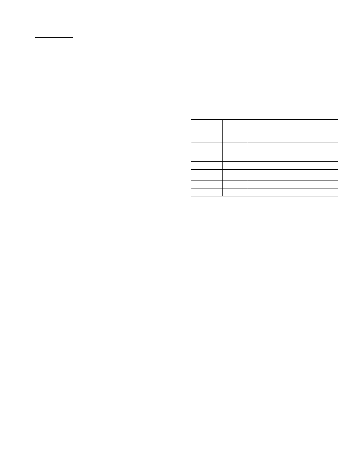
Table 10 — Unit Diagnostic Guides
☆ = Flashing, X = Off
For additional diagnostic information, refer to the service manual.
GREEN LED RED LED FAILURE MODE
On X Standby, normal
X On Operation, normal
On On
High/Low voltage protection on
compressor terminal
On ☆ EEPROM error
X ☆ The compressor speed is out of control
☆ On
Zero-crossing signal detection error; lack
of phase; synchronization error
☆ X IGBT or Module protection
☆☆Communication error
Loading ...
Loading ...
Loading ...