Specifications subject to change without notice.
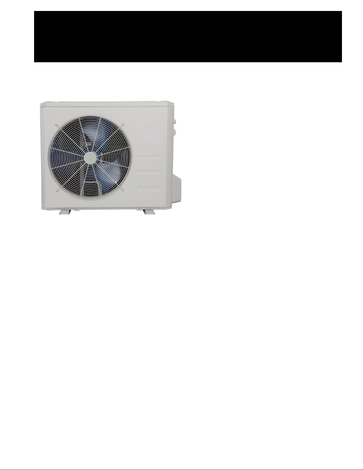
Fig. 1 —Sizes 9K to 36K
NOTES: Read the entire instruction manual before
starting the installation.
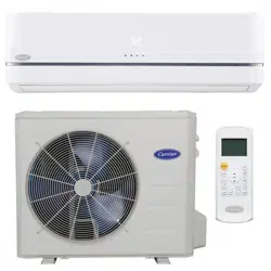
Images are for illustration purposes only. Actual
models may differ slightly.
TABLE OF CONTENTS
PAGE
SAFETY CONSIDERATIONS........................................................2
ACCESSORIES................................................................................2
DIMENSIONS..................................................................................4
CLEARANCES ................................................................................8
INSTALLATION REQUIREMENTS .............................................9
INSTALLATION .............................................................................9
Step 1 - Check Equipment ................................................................9
Step 2 - Mount Unit ..........................................................................9
Step 3 - Condensate Drain Installation .............................................10
Step 4 - Refrigerant Piping ...............................................................11
Step 5 - Evacuate Coil And Tubing System .....................................14
Step 6 - Electrical Connections.........................................................15
WIRING ...........................................................................................15
ELECTRICAL DATA......................................................................16
CONNECTION DIAGRAMS ..........................................................16
START-UP .......................................................................................17
CARE AND MAINTENANCE........................................................17
TROUBLESHOOTING ...................................................................17
OUTDOOR UNIT DIAGNOSTIC GUIDES ...................................18
DUCTLESS START-UP CHECKLIST ...........................................19
Installation Instruction
38MARB
Outdoor Unit Single Zone Ductless System
Sizes 09 to 36
2 Specifications subject to change without notice. 38MARB-01SI
SAFETY CONSIDERATIONS
Installing, starting up, and servicing air- conditioning equipment can
be hazardous due to system pressures, electrical components, and
equipment location (roofs, elevated structures, etc.).
Only trained, qualified installers and service mechanics should install,
start- up, and service this equipment.
Untrained personnel can perform basic maintenance functions such
as coil cleaning. All other operations should be performed by trained
service personnel only.
When working on the equipment, observe the precautions in the
literature and on tags, stickers, and labels attached to the equipment.
Follow all safety codes.Wear safety glasses and work gloves. Keep a
quenching cloth and a fire extinguisher nearby when brazing. Use care
in handling, rigging, and setting bulky equipment.
Read these instructions thoroughly and follow all warnings or
cautions included in the literature and attached to the unit. Consult
local building codes and National Electrical Code (NEC) for special
requirements. Recognize safety information.
This is the safety - alert symbol . When you see this symbol on
the unit and in instructions or manuals, be alert to the potential for
personal injury. Understand these signal words: DANGER,
WARNING, and CAUTION. These words are used with the
safety- alert symbol.
DANGER identifies the most serious hazards which will result in
severe personal injury or death.
WARNING signifies hazards which could result in personal injury or
death.
CAUTION is used to identify unsafe practices which may result in
minor personal injury or product and property damage.
NOTE is used to highlight suggestions which will result in enhanced
installation, reliability, or operation.
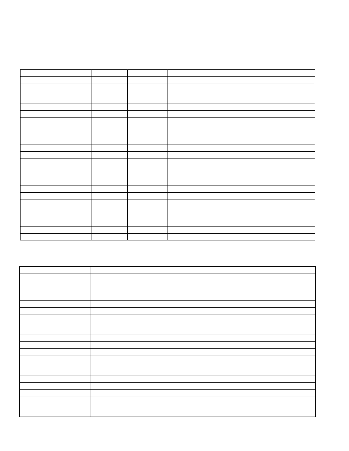
ACCESSORIES
The system is shipped with the following accessories. Use all of the
installation parts and accessories to install the system. Improper
installation may result in water leakage, electrical shock and fire, or
cause the equipment to fail. Keep the installation manual in a safe
place and do not discard any other accessories until the installation
work has been completed.
Table 1 —Accessories
PART
NO.
PART NAME QTY.
1 Outdoor unit 1
-
Literature package including installation instructions
and warranty
1
-
Mounting pads for the outdoor unit (helps with
vibration prevention during unit operation)
4
-Drain Joint 1
-Drain Hose 1
ELECTRICAL SHOCK HAZARD
Failure to follow this warning could result in personal injury or
death.
Before installing, modifying, or servicing system, the main
electrical disconnect switch must be in the OFF position. There
may be more than 1 disconnect switch. Lock out and tag switch
with a suitable warning label.
WA RNING
EXPLOSION HAZARD
Failure to follow this warning could
result in death, serious personal injury,
and/or property damage.
Never use air or gases containing oxygen
for leak testing or operating refrigerant
compressors. Pressurized mixtures of air
or gases containing oxygen can lead to an
explosion.
WARN I NG
EQUIPMENT DAMAGE HAZARD
Failure to follow this caution may result in equipment damage or
improper operation.
Do not bury more than 36 in. (914 mm) of refrigerant pipe in the
ground. If any section of pipe is buried, there must be a 6 in. (152
mm) vertical rise to the valve connections on the outdoor units. If
more than the recommended length is buried, refrigerant may
migrate to the cooler buried section during extended periods of
system shutdown. This causes refrigerant slugging and could
possibly damage the compressor at start-up.
CAUTION
38MARB-01SI Specifications subject to change without notice. 3
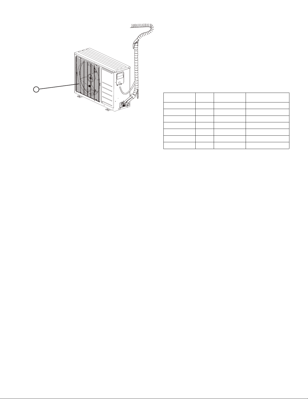
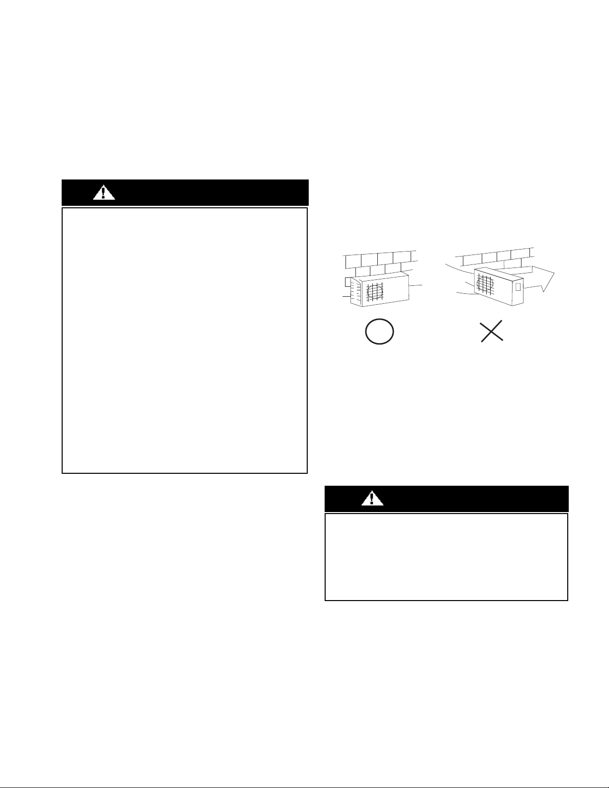
Fig. 2 — Outdoor Unit
NOTE:
- If the outdoor unit is higher than the indoor unit, prevent
rain from flowing into the indoor unit along the connection
pipe by making a downward arc in the connection pipe
before it enters the wall to the indoor unit. This ensures that
rain drips from the connection pipe before it enters the
wall.
- Piping and the interconnecting wiring are field supplied.
- Figure 2 is only a sketch. The actual model may differ
slightly.
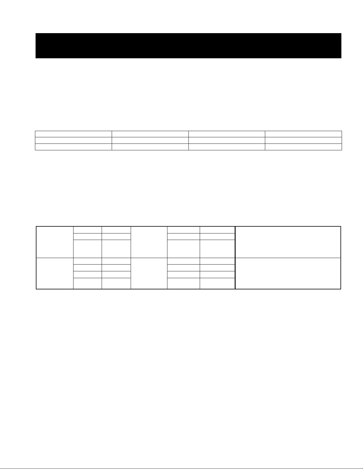
Table 2 lists the units covered in this document.
Table 2 — Unit Sizes
Ŷ2XWGRRUXQLW
SYSTEM TONS BTUH
VOLTAGE -
PHASE
OUTDOOR MODEL
1.00 12,000 115-1 38MARBQ12AA1
0.75 9,000 208/230-1 38MARBQ09AA3
1.00 12,000 208/230-1 38MARBQ12AA3
1.50 18,000 208/230-1 38MARBQ18AA3
2.00 24,000 208/230-1 38MARBQ24AA3
2.50 30,000 208/230-1 38MARBQ30AA3
3.00 36,000 208/230-1 38MARBQ36AA3

4 Specifications subject to change without notice. 38MARB-01SI
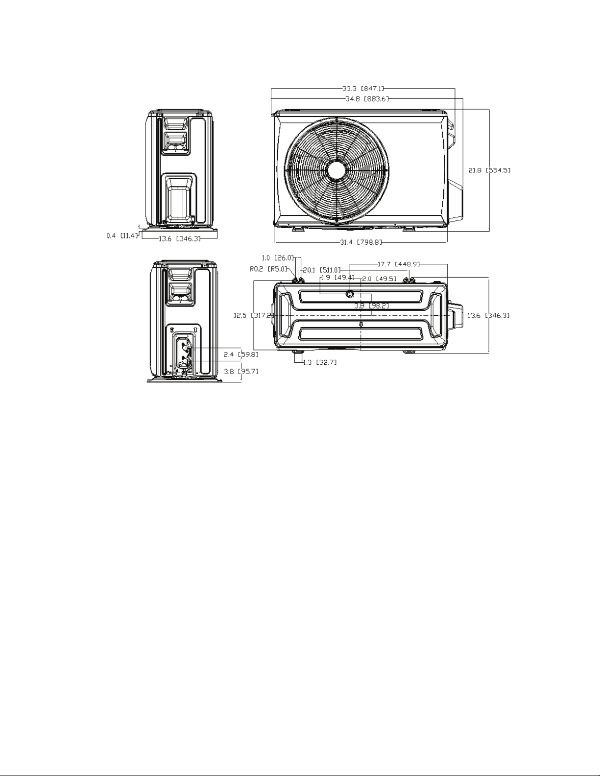
DIMENSIONS
Fig. 3 — Size 12K (115V)
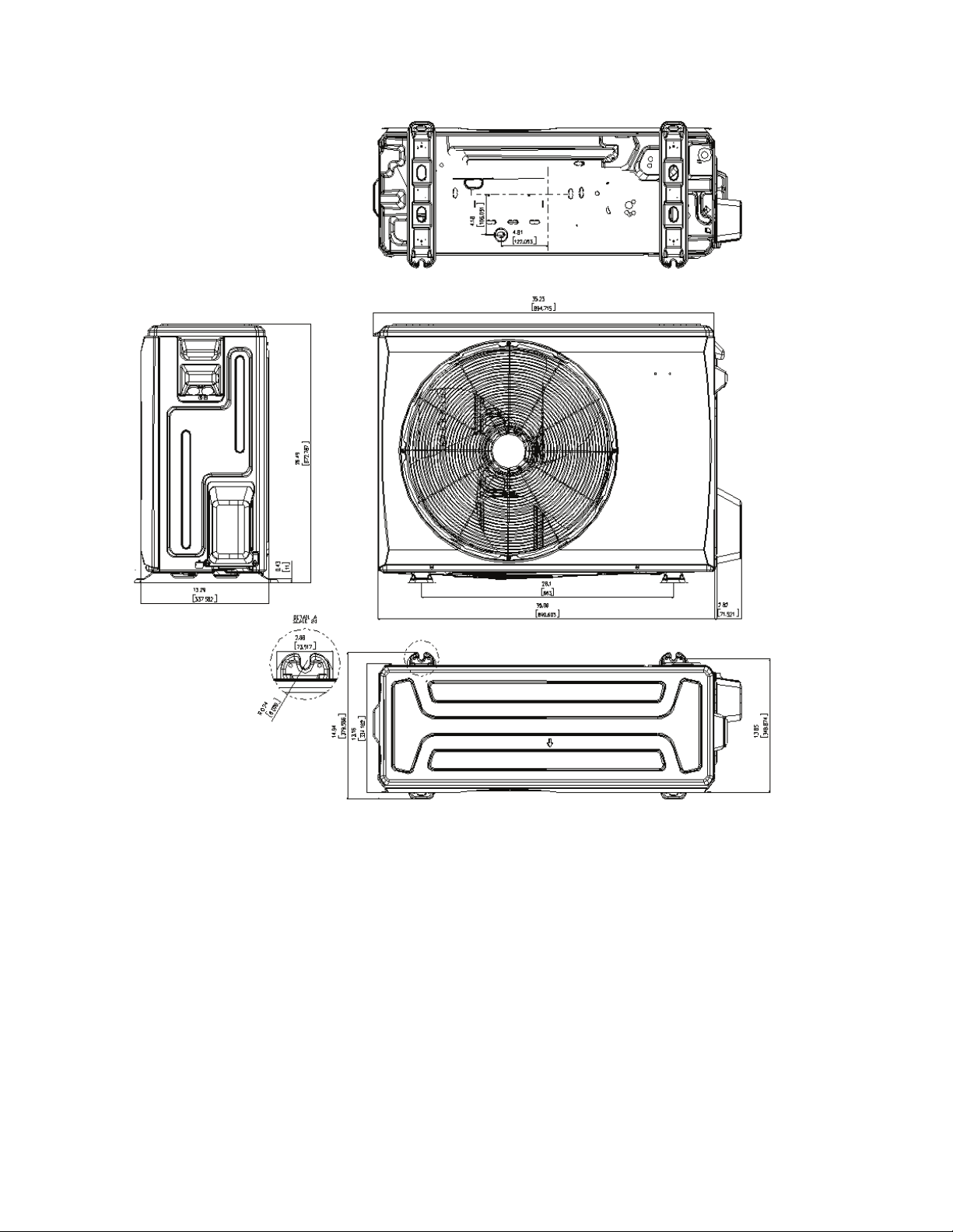
System Size
12K 9K 12K 18K 24K 30K 36K
(115V) (208/230V) (208/230V) (208/230V) (208/230V) (208/230V) (208/230V)
Outdoor Unit
Unit
Height (H) in (mm) 21.85 (555) 21.81 (554) 21.81 (554) 26.50 (673) 31.89 (810) 31.89(810) 31.89 (810)
Width (W) in (mm) 30.12 (765) 31.69 (805) 31.69 (805) 35.04 (890) 37.24 (946) 37.24(946) 37.24 (946)
Depth (D) in (mm) 11.93 (303) 12.99 (330) 12.99 (330) 13.46 (342) 16.14 (410) 16.14(410) 16.14 (410)
Weight -
Net
lbs. (kg) 66.80 (30.3) 74.07 (33.6) 73.63 (33.4) 100.97 (45.8) 134.48 (61) 141.76(64.3) 150.13 (68.1)
Packaging
Height in (mm) 24.02 (610) 24.21 (615) 24.21 (615) 29.13 (740) 34.84 (885) 34.84(885) 34.84 (885)
Width in (mm) 34.92 (887) 36.02 (915) 36.02 (915) 39.17 (995) 42.91 (1090) 42.91(1090) 42.91 (1090)
Depth in (mm) 13.27 (337) 14.57 (370) 14.57 (370) 15.67 (398) 19.69 (500) 19.69(500) 19.69 (500)
Weight -
Gross
lbs. (kg) 72.31 (32.8) 80.25 (36.4) 79.37 (36) 108.03 (49) 144.40 (65.5) 151.90(68.9) 158.95 (72.1)
Carton
Drawing
No.
-- 877*327*590 905*360*590 905*360*590 985*388*720 1075*485*86 1075*485*86 1075*485*86
Carton
Material
-- Carton Box
Material
Thickness
in (mm) 0.197 (5) 0.197 (5) 0.197 (5) 0.197 (5) 0.295 (7.5) 0.295(7.5) 0.295 (7.5)
38MARB-01SI Specifications subject to change without notice. 5
DIMENSIONS (CONT)
Fig. 4 — Sizes 9K-12K (208/230V)
6 Specifications subject to change without notice. 38MARB-01SI
DIMENSIONS (CONT)
Fig. 5 — Size 18K (208/230V)
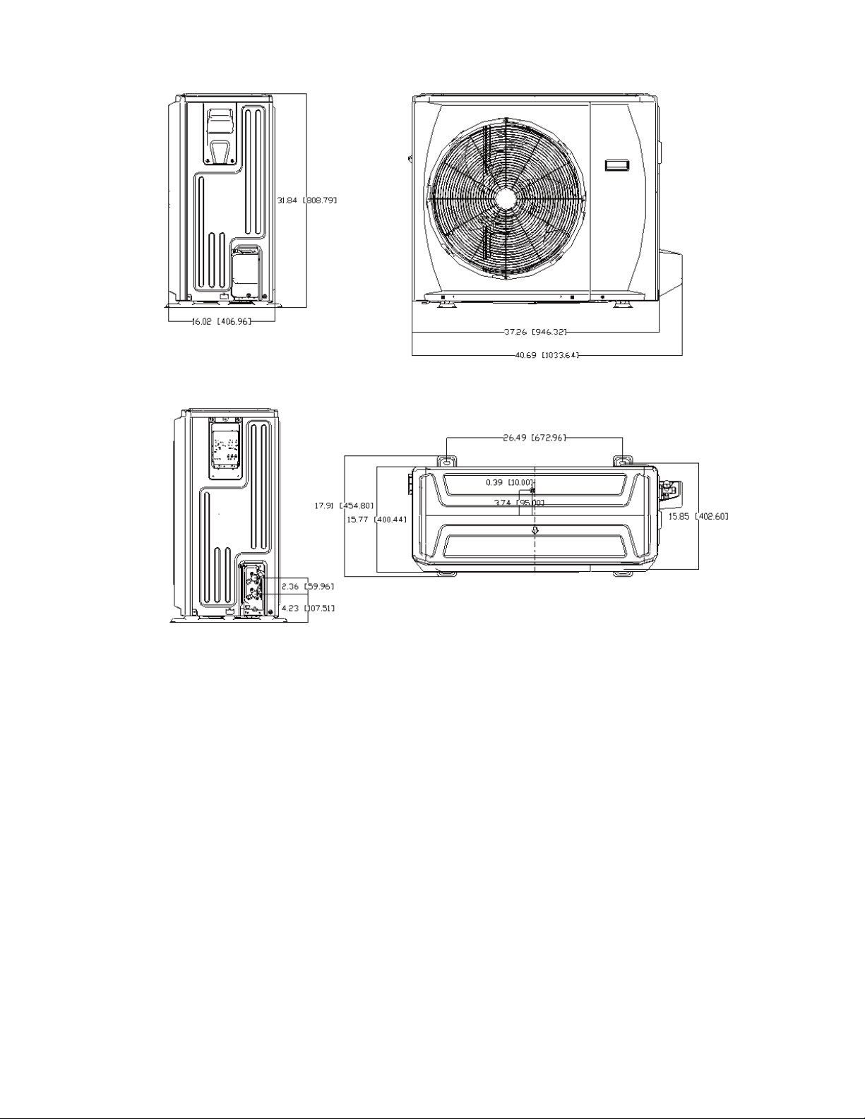
38MARB-01SI Specifications subject to change without notice. 7
DIMENSIONS (CONT)
Fig. 6 — Sizes 24K, 30K, and 36K (208/230V)
8 Specifications subject to change without notice. 38MARB-01SI
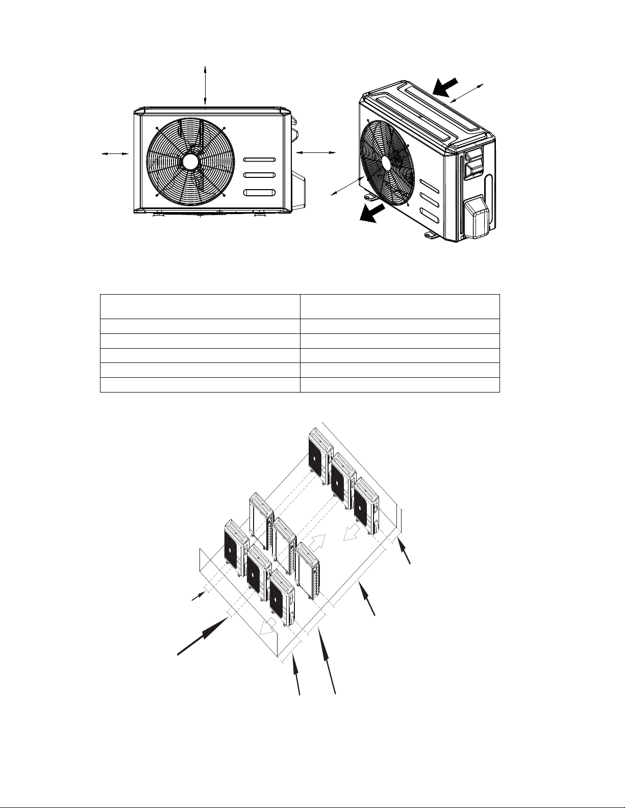
CLEARANCES
Fig. 7 — Clearances
Table 3 — Clearance Dimensions
NOTE: The outdoor unit must be mounted at least 2in (50mm) above the maximum anticipated snow depth.
Fig. 8 — Clearances for multiple units
UNIT
MINIMUM VALUE
IN. (MM)
A 24 (610)
B 24 (610)
C 24 (610)
D 4 (101)
E 4 (101)
D
B
A
E
C
Air inlet
Air outlet
59in (150cm)
or more when
facing each other
Blowing into the air-inlet of other
condenser shall be avoided.
24in (60cm)
or more
59in (150cm)
or more on a
multiple parallel
unit arrangement
24in (61cm) or more on a single parallel unit arrangement
19in (48cm) or more on
a multiple parallel unit
arrangement 4in (10cm)
or more on a single
parallel unit arrangemen
9.8in (25cm) or more for proper airflow
24in (61cm) or more is recommended
for service
9.8in (25cm) or more for
proper airflow 24in(61cm)
or more is
recommended
for service
38MARB-01SI Specifications subject to change without notice. 9
INSTALLATION REQUIREMENTS
• A location which is convenient to installation and not exposed to
strong winds.
• A location which can bear the weight of the outdoor unit and
where the outdoor unit can be mounted in a level position.
• A location which provides appropriate clearances (see Fig. 7).
• Allow sufficient space for airflow and service of the unit. See Fig.
7 for the required minimum distances between the unit or walls.
NOTE: DO NOT install the indoor or outdoor units in a location with
special environmental conditions. For those applications, contact your
Ductless representative.
INSTALLATION
Step 1 - Check Equipment
Unpack the unit and move to the final location. Remove the carton,
taking care not to damage the unit. Inspect the equipment for damage
prior to installation. File a claim with the shipping company if the
shipment is damaged or incomplete.
Locate the unit rating plate which contains the proper installation
information. Check the rating plate to ensure the unit matches the job
specifications.
Step 2 - Mount Unit
1. Select the installation location of the outdoor unit following the
installation requirements. To prevent high wind exposure, install the
outdoor unit with the air inlet side facing the wall (see fig 9).
Fig. 9 — High Wind Installation
2. Use a rigid base to support the unit in a level position. If conditions
or local codes require the unit be attached to a pad, tie down bolts
should be used and fastened through knockouts provided in unit
base pan. Refer to unit mounting pattern in Fig. 3 to determine base
pan size and knockout hole location. For hurricane tie downs,
contact distributor for details and PE (Professional Engineer)
Certification, if required. For extreme outdoor conditions
applications refer to the 'Cold Climate Application Guideline
Ductless.
PRODUCT INSTALLATION
• Installation must be performed by an authorized dealer or
specialist. A defective installation can cause water leakage,
electrical shock, or fire.
• The installation must be performed according to the installation
instructions. Improper installation can cause water leakage,
electrical shock, or fire. (In North America, installation must be
performed in accordance with the requirements of NEC or CEC
by authorized personnel only.)
• Contact an authorized service technician for repair or
maintenance of this unit. This appliance must be installed in
accordance with local codes.
• Only use the included accessories, parts, and specified parts for
installation. Using non-standard parts can cause water leakage,
electrical shock, fire, or unit failure.
• To prevent exposure to wind, install the outdoor unit with its air
inlet side facing the wall
• Install drainage piping according to the instructions in this
manual. Improper drainage may cause water damage to your
home and property.
• DO NOT install the unit in a location that may be exposed to
combustible gas leaks. If combustible gas accumulates around
the unit, it may cause a fire.
• DO NOT turn on the power until all work has been completed.
• When moving or relocating the system, consult experienced
service technicians for the disconnection and re-installation of
the unit.
WA RNING
Strong
wind
EQUIPMENT DAMAGE HAZARD
Failure to follow this caution may result in equipment damage or
improper operation.
In regions with snowfall and cold temperatures, avoid installing
the outdoor unit in areas where it can be covered by snow.
Blocking the air intake may result in reduced airflow, significantly
reduced performance and damage to the equipment.
CAUTION
10 Specifications subject to change without notice. 38MARB-01SI
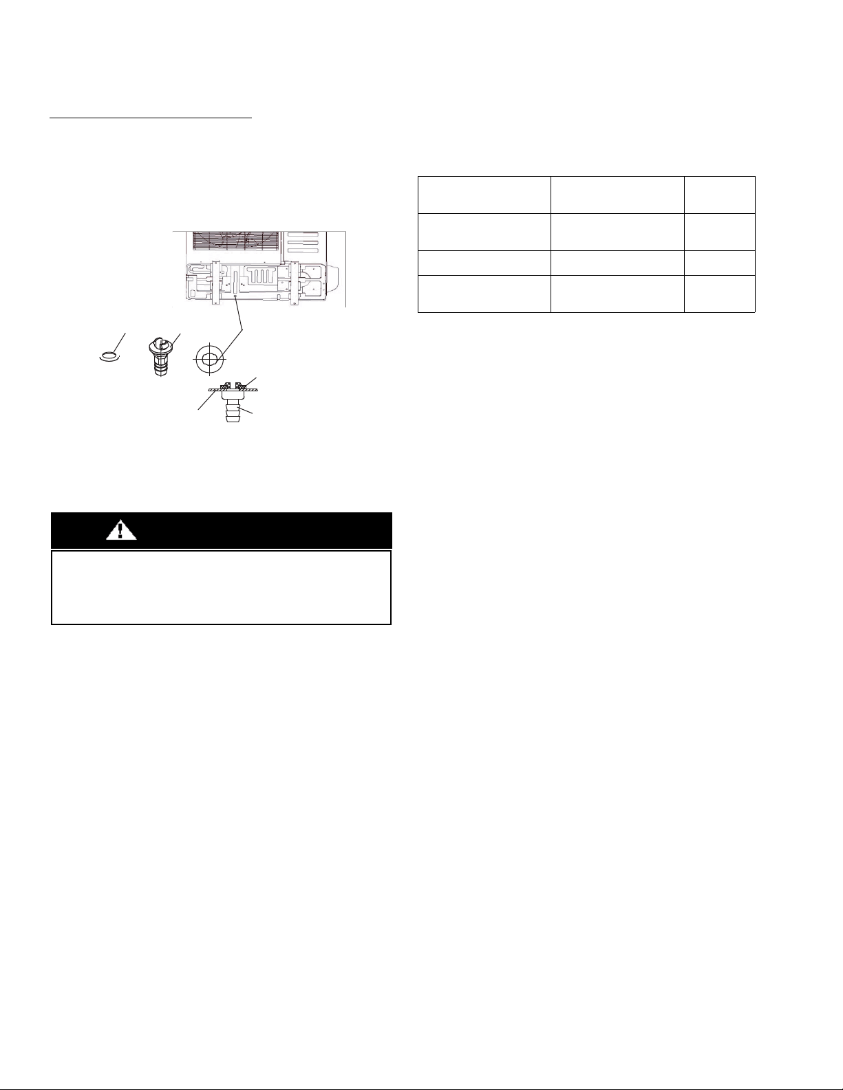
Step 3 - Condensate Drain Installation
NOTE: Install drains must meet local sanitation codes.
Install the outdoor unit drain joint
Fit the seal into the drain joint, then insert the drain joint into the base
pan hole of the outdoor unit. Rotate 90° to securely assemble them.
Connect the drain joint with an extension drain hose to avoid
condensate from draining off the outdoor unit during the heating
mode.
Fig. 10 — Drain Joint
NOTE: Images are for illustration purposes only.
NOTE: Basepan built-in with multiple holes for proper draining
during defrost. For applications where it is required to seal
these holes, and re-direct the condensate drain, rubber plugs
are available through RCD.
Table 4 — Base Pan Rubber Plugs
Seal
Base pan hole
Drain joint
Seal
Base pan
Drain
joint
EQUIPMENT DAMAGE HAZARD
In cold climates, ensure the drain hose is as vertical as possible to
ensure swift water drainage. If water drains too slowly, it can freeze
in the hose and flood the unit.
CAUTION
OUTDOOR UNIT
MODEL NUMBER
PER UNIT
BASE PAN RUBBER
PLUGS RCD PART
NUMBER
QUANTITY
38MARBQB12R--1
38MARBQB09R--3
38MARBQB12R--3
12600801A00077 13
38MARBQB18R--3 12600801A00077 25
38MARBQB24R--3
38MARBQB30R--3
38MARBQB36R--3
12600801A00117 5
38MARB-01SI Specifications subject to change without notice. 11
Step 4 - Refrigerant Piping
Table 5 — Piping and Refrigerant
IMPORTANT: Both refrigerant lines must be insulated
separately. Use refrigeration grade tubing ONLY. No other
type of tubing may be used. Use of other types of tubing
will void the manufacturer's warranty.
• The minimum refrigerant line length between the indoor and
outdoor unit is 10 ft. (3m).
• When paired with Ductless indoor units, size the line sets based on
the connection size of the indoor unit unless specified.
• When paired with conventional or multi-family fan coils, size the
line sets based on the liquid and gas connection size of the outdoor
unit; a field supplied reducer may be required.
• All outdoor units have an electronic expansion valve to manage the
refrigerant flow of the fan coil connected.
• Do not open the service valves or remove the protective caps from
the tubing ends until all connections are made.
• Bend the tubing with bending tools to avoid kinks and flat spots.
• Keep the tubing free of dirt, sand, moisture, and other
contaminants to avoid damaging the refrigerant system.
• Avoid sags in the suction line to prevent the formation of oil traps.
• Insulate each tube with a minimum 3/8-in. (10 mm) wall thermal
pipe insulation. Inserting the tubing into the insulation before
making the connections will save time and improve installation
quality.
System Size
12K
(115V)
9K
(208/230V)
12K
(208/230V)
18K
(208/230V)
24K
(208/230V)
30K
(208/230V)
36K
(208/230V)
Piping
Min. Piping Length ft.(m) 9.8(3) 9.8(3) 9.8(3) 9.8(3) 9.8(3) 9.8(3) 9.8(3)
Standard Piping
Length
ft.(m) 24.6 (7.5) 24.6 (7.5) 24.6 (7.5) 24.6 (7.5) 24.6 (7.5) 24.6 (7.5) 24.6 (7.5)
Max. outdoor-indoor
height difference
(OU higher than IU)
ft.(m) 32.8 (10) 32.8 (10) 32.8 (10) 65.6 (20) 82 (25) 82 (25) 98.4 (30)
Max. outdoor-indoor
height difference
(IU higher than OU)
ft.(m) 32.8 (10) 32.8 (10) 32.8 (10) 65.6 (20) 82 (25) 82 (25) 98.4 (30)
Max. Piping Length
with no additional
refrigerant charge
per System
(Standard Piping
length)
ft.(m) 24.6 (7.5) 24.6 (7.5) 24.6 (7.5) 24.6 (7.5) 24.6 (7.5) 24.6 (7.5) 24.6 (7.5)
Total Maximum
Piping Length per
system
ft.(m) 82 (25) 82 (25) 82 (25) 98.4 (30) 164 (50) 164 (50) 213 (65)
Additional refrigerant
charge (between
Standard – Max
piping length)
Oz/ft
(g/m)
0.161(15) 0.161(15) 0.161(15) 0.161(15) 0.322(30) 0.322(30) 0.322(30)
Suction Pipe (size -
connection type)
In
(mm)
ø1/2” (12.7) ø3/8” (9.52) ø1/2” (12.7) ø1/2” (12.7) ø5/8” (15.9) ø5/8” (15.9) ø5/8” (15.9)
Refrigerant
Refrigerant Type Type R410A R410A R410A R410A R410A R410A R410A
Charge Amount
lb.
(kg)
2.47(1.12) 2.6(1.18) 2.6(1.18) 4.08(1.85) 5.73(2.6) 6.06(2.75) 7.5(3.4)
All field piping must be completed by a licensed technician and
must comply with the local and national regulations.
When the system is installed in a small room, measures must be
taken to prevent the refrigerant concentration in the room from
exceeding the safety limit in the event of refrigerant leakage. If the
refrigerant leaks and its concentration exceeds its proper limit,
hazards due to lack of oxygen may result.
When installing the refrigeration system, ensure that air, dust,
moisture or foreign substances do not enter the refrigerant circuit.
Contamination in the system may cause poor operating capacity,
high pressure in the refrigeration cycle, explosion or injury.
Ventilate the area immediately if there is refrigerant leakage
during the installation.
Leaked refrigerant gas is hazardous. Ensure there is no refrigerant
leakage after completing the installation work.
WARNING
DO NOT install the connecting pipe until both the indoor and
outdoor units have been installed.
Insulate both the gas and liquid piping to prevent condensation.
CAUTION
12 Specifications subject to change without notice. 38MARB-01SI
Use the following steps to connect the refrigerant piping:
1. Run the interconnecting piping from the outdoor unit to the indoor
unit.
2. Connect the refrigerant piping and drain line outside the indoor
unit. Complete the pipe insulation at the flare connection then
fasten the piping and wiring to the wall as required. Completely seal
the hole in the wall.
3. Cut tubing to the correct length.
When preparing refrigerant pipes, take extra care to cut and
flare them properly. This ensures efficient operation and
minimizes the need for future maintenance.
a. Measure the distance between the indoor and outdoor units.
b. Using a pipe cutter, cut the pipe a little longer than the
measured distance.
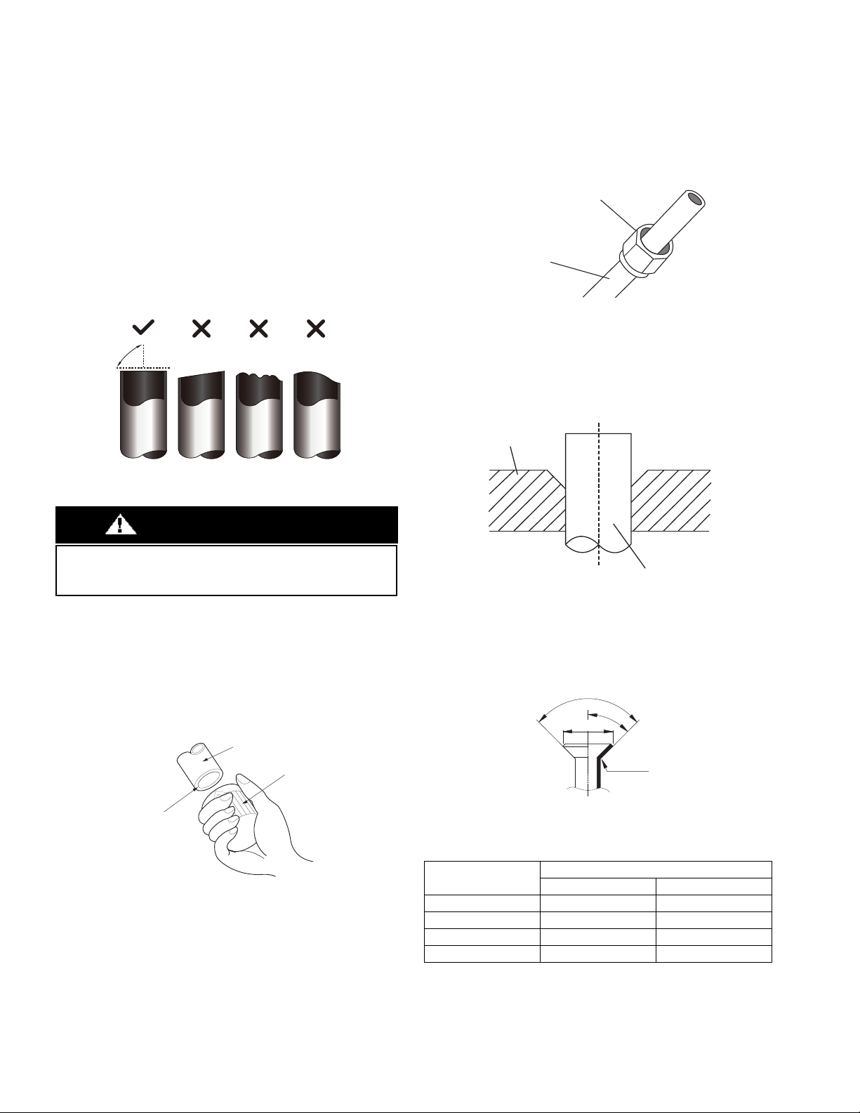
c. Make sure the pipe is cut at a perfect 90° angle.
Fig. 11 —Pipe Cutting
4. Remove Burrs
Burrs can affect the air-tight seal of the refrigerant piping connection.
Therefore, they must be completely removed. To remove:
a. Hold the pipe at a downward angle to prevent burrs from
falling into the pipe.
b. Using a reamer or deburring tool, remove all burrs from the
cut section of the pipe.
Fig. 12 — Deburring Tool
5. Flare Pipe Ends
Proper flaring is essential to achieving an airtight seal.
a. After removing the burrs from the cut pipe, seal the ends with
PVC tape to prevent foreign materials from entering the pipe.
b. Sheath the pipe with insulating material.
c. Place factory flare nut on pipe facing the proper direction.
Make sure they are facing the right direction. Once the ends are
flared, it is impossible to put them on or change their direction.
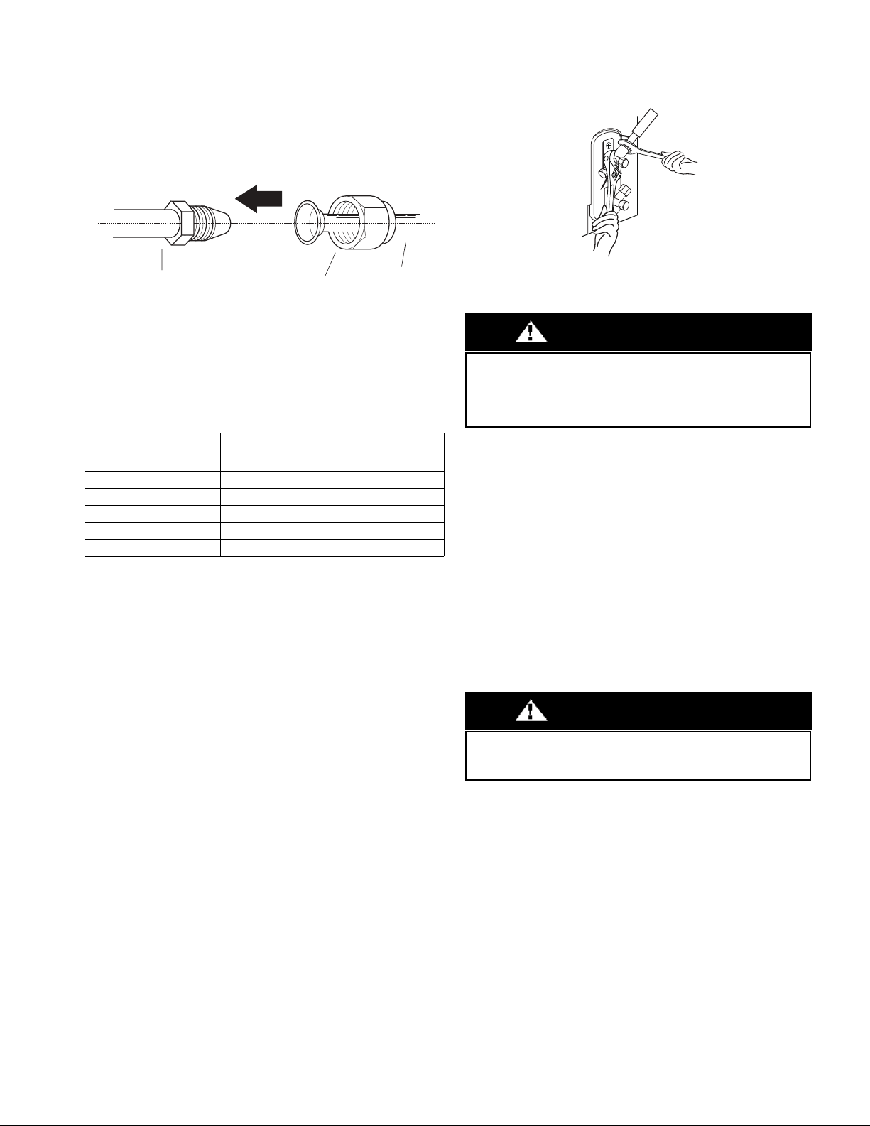
Fig. 13 — Copper pipe and flare nut
d. Remove the PVC tape from ends of pipe when ready to perform
the flaring work.
e. Clamp the flare block on the end of the pipe. The end of the
pipe must extend beyond the flare form.
Fig. 14 — Flare Block
f. Place the flaring tool onto the form.
g. Turn the handle of the flaring tool clockwise until the pipe is fully
flared. Flare the pipe in accordance with the dimensions in Table 6.
Fig. 15 — Flare Shape
Table 6 — Flare Nut Spacing
h. Remove the flaring tool and flare block, then inspect the end
of the pipe for cracks and even flaring.
Oblique Rough
Warped
90°
DO NOT DEFORM PIPE WHILE CUTTING
Be extra careful not to damage, dent, or deform the pipe while
cutting. This will drastically reduce the heating efficiency of the unit.
CAUTION
Pipe
Reamer
Point down
OUTER DIAMETER
IN (MM)
A” IN (MM)
MAX. MIN.
Ø 1/4” (6.35) 0.05 (1.3) 0.03 (0.7)
Ø 3/8” (9.52) 0.06 (1.6) 0.04 (1.0)
Ø 1/2” (12.7) 0.07 (1.8) 0.04 (1.0)
Ø 5/8” (15.88) 0.09 (2.2) 0.08 (2.0)
Flare nut
Copper pipe
Flare block
Pipe
R0.4~0.8
45
q
r
2
90
q
r
4
A
38MARB-01SI Specifications subject to change without notice. 13
6. Connect the Pipes
Connect the copper pipes to the indoor unit first, then connect
the pipes to the outdoor unit. Connect the low-pressure pipe
first, then connect the high pressure pipe.
a. When connecting the flare nuts, apply a thin coat of
refrigeration oil to the flared ends of the pipes.
b. Align the center of the two pipes that you will connect.
Fig. 16 — Align the center of the two pipes
c. Tighten the flare nut as much as possible by hand.
d. Using a wrench, grip the nut on the unit tubing.
e. While firmly gripping the nut, use a torque wrench to
tighten the flare nut according to the torque values listed in
Table 7.
Table 7 — Tightening Torque
NOTE: Use both a backup wrench and a torque wrench when
connecting or disconnecting pipes to or from the unit.
Fig. 17 — Torque wrench with backup wrench
All tubing bends should be performed with a properly sized tubing
bender to prevent kinking or damaging the tubing.
f. After connecting the copper pipes to the indoor unit, wrap
the power cable, signal cable and the piping together with
binding tape.
NOTE: While bundling these items together, DO NOT intertwine or
cross the signal cable with any other wiring.
g. Thread this lineset through the wall and connect it to the
outdoor unit.
h. Insulate all piping, including the outdoor unit valves.
NOTE: DO NOT open the service valves until pressure test is
complete.
7. Pressure Test Piping
NOTE: Use refrigeration gauges that are pressure rated for
R410a refrigerant.
a. Attach low side gauge hose to the 5/16" Schrader valve on
the outdoor unit service valve.
b. Attach the charging hose to the regulator on the dry nitrogen
tank.
c. Preset the nitrogen regulator to 550 psi.
d. Slowly pressurize the line set until the low side gauge reads
500 psi. Do not exceed 550 psi.
e. Close all the valves on the nitrogen tank and gauges.
f. Allow the pressure test to stand for a minimum of 30
minutes.
g. If the pressure holds, release the nitrogen and proceed with
“Step 5 - Evacuate Coil And Tubing System” on page 14.
h. If the pressure goes down in the 30 minute delay, leak check
the tubing and flare fittings to identify the source of the
leak. Return to Step C, above.
BRASS FLARE SIZE
(IN”)
RECOMMENDED SEATING
TORQUE FOR BRASS
FLARE NUTS
N-M
Ø1/4 8-10 Ft. - Lbs. 10.8 to 13.6
Ø3/8 15-18 Ft. - Lbs 20.3 to 24.4
Ø1/2 28-32 Ft. - Lbs 38.0 to 43.4
Ø5/8 38-42 Ft. - Lbs 51.5 to 56.9
Ø3/4 50-55 Ft. - Lbs. 68.0 to 74.6
Pipe
Indoor unit tubing
Flare nut
Wrap insulation around the piping. Direct contact with the bare
piping may result in burns or frostbite. Ensure the pipe is properly
connected. Over tightening may damage the bell mouth and under
tightening may lead to leakage.
CAUTION
Only use Dry Nitrogen to pressure test refrigerant systems. Use of
other gases can result in injury, property damage or death.
CAUTION
14 Specifications subject to change without notice. 38MARB-01SI
Step 5 - Evacuate Coil And Tubing System
Refrigerant tubes and the indoor coil should be evacuated using the
recommended 500 microns deep vacuum method. The alternate triple
evacuation method may be used if the procedure outlined below is
followed.
NOTE: Always break a vacuum with dry nitrogen.
Using Vacuum Pump
1. Completely tighten flare nuts A, B, C, D. Connect the manifold
gage charge hose to a charge port of the low side service valve (see
Fig. 18).
2. Connect the charge hose to vacuum pump.
3. Fully open the low side of manifold gage (see Fig. 19).
4. Start the vacuum pump.
5. Evacuate using either the deep vacuum or triple evacuation method.
6. After evacuation is complete, fully close the low side of manifold
gage and stop the vacuum pump operation.
7. The factory charge contained in the outdoor unit is good for up to
25 ft. (8 m) of line length. For refrigerant lines longer than 25 ft. (8
m), add refrigerant, up to the allowable length.
8. Disconnect the charge hose from the charge connection of the low
side service valve.
9. Fully open service valves B and A.
10. Securely tighten the service valve caps.
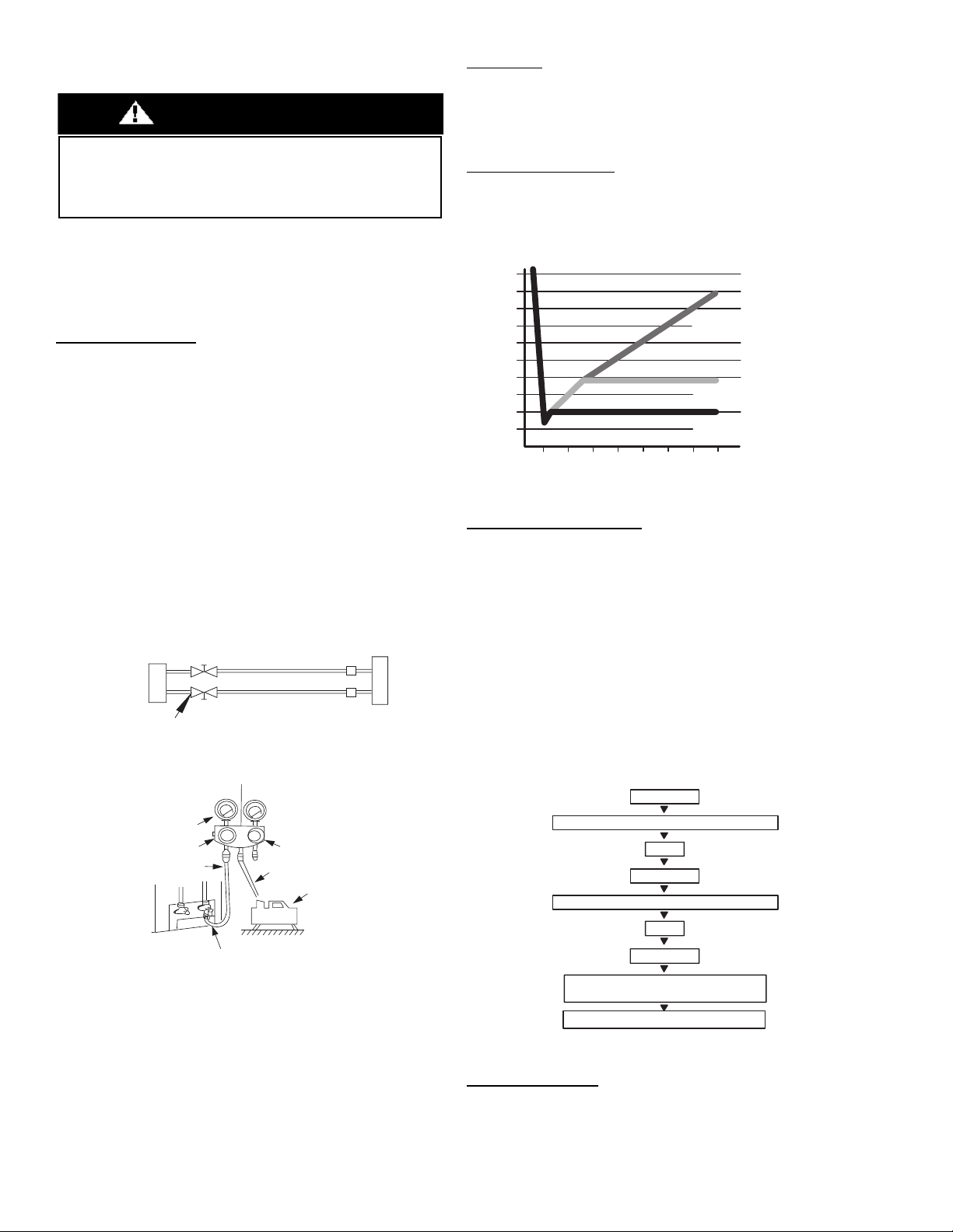
Fig. 18 — Service Valve
Fig. 19 — Manifold
Evacuation
Evacuation of the system will remove air or nitrogen (non-condensables)
as well as moisture. A proper vacuum will assure a tight, dry system
before charging with refrigerant. The two methods used to evacuate a
system are the deep vacuum method and the triple vacuum method.
Deep Vacuum Method
The deep vacuum method requires a vacuum pump capable of pulling a
vacuum of 500 microns and a vacuum gauge capable of accurately
measuring this vacuum depth. The deep vacuum method is the most positive
way of assuring a system is free of air and moisture (see Figure 20).
Fig. 20 — Deep Vacuum Graph
Triple Evacuation Method
The triple evacuation method should be used when vacuum pump
is not capable of pumping down to 500 microns and system does not
contain any liquid water. Refer to Fig. 21 and proceed as follows:
1. Attach refrigeration gauges and evacuate system down to 28 in. of
mercury and allow pump to continue operating for an additional 15
minutes.
2. Close service valves and shut off vacuum pump.
3. Connect a nitrogen cylinder and regulator to system and flow
nitrogen until system pressure is 2 psig.
4. Close service valve and allow system to stand for 1 hour. During
this time, dry nitrogen will be able to diffuse throughout the system
absorbing moisture.
5. Repeat this procedure as indicated in Fig. 21. System will then be
free of any contaminants and water vapor.
Fig. 21 — Triple Evacuation Method
Final Tubing Check
IMPORTANT: Check to be certain factory tubing on both the
indoor and outdoor unit has not shifted during shipment. Ensure
tubes are not rubbing against each other or any sheet metal. Pay
close attention to the feeder tubes, making sure wire ties on feeder
tubes are secure and tight.
UNIT DAMAGE HAZARD
Failure to follow this caution may result in equipment damage or
improper operation.
Never use the system compressor as a vacuum pump.
CAUTION
Outdoor Unit Indoor UnitRefrigerant
Service Valve
Low Side
High Side
A
B
C
D
500 microns
Low side valve
High side valve
Charge hose
Charge hose
Vacuum
pump
Low side valve
500
MINUTES
01234567
1000
1500
LEAK IN
SYSTEM
SYSTEM TIGHT
EVACUATE MOISTURE
TIGHT DRY SYSTEM
2000
MICRONS
2500
3000
3500
4000
4500
5000
CHECK FOR TIGHT, DRY SYSTEM
(IF IT HOLDS DEEP VACUUM)
EVACUATE
BREAK VACUUM WITH DRY NITROGEN
WAIT
EVACUATE
RELEASE CHARGE INTO SYSTEM
BREAK VACUUM WITH DRY NITROGEN
EVACUATE
WAIT
38MARB-01SI Specifications subject to change without notice. 15
Step 6 - Electrical Connections
Install All Power and Interconnecting Wiring to
Outdoor Units
1. Mount the outdoor power disconnect.
2. Run the power wiring from the main box to disconnect per NEC
and local codes.
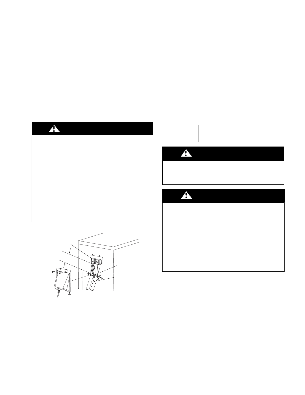
3. Remove the field wiring cover from the unit by loosening the
screws.
4. Remove the caps on the conduit panel.
5. Connect the conduit to conduit panel (see Fig. 22).
6. Properly connect both the power supply and control lines to the
terminal block per the connection diagram for the appropriate unit
capacity and voltage.
7. Ground the unit in accordance with NEC and local electrical codes.
8. Use the lock nuts to secure the conduit.
9. Reinstall the field wiring cover.
Fig. 22 —Field Wiring
WIRING
All wires must be sized per NEC (National Electrical Code) or CEC
(Canadian Electrical Code) and local codes. Use Electrical Data table MCA
(minimum circuit amps) and MOCP (maximum over current protection) to
correctly size the wires and the disconnect fuse or breakers respectively.
Power and Communication Wiring: The main power is supplied to
the outdoor unit. The field supplied 14/3 power/communication
wiring, from the outdoor unit to the indoor unit, consists of four (4)
wires and provides the power for the indoor unit. Two wires are high
voltage AC power, one is communication wiring and the other is a
ground wire.
To minimize communication interference: If installed in a high
Electromagnetic field (EMF) area and communication issues arise, a
14/2 stranded shielded wire can be used to replace 2 (L2/N) and 3 (S)
between the outdoor and indoor units - landing the shield onto the
ground in the outdoor unit only.
Table 8 — Wiring Sizes
EQUIPMENT DAMAGE HAZARD
Failure to follow this caution may result in equipment damage or
improper operation.
Be sure to comply with local codes while running wire from
indoor unit to outdoor unit.
Every wire must be connected firmly. Loose wiring may cause the
terminal to overheat or result in unit malfunction. A fire hazard
may also exist. Therefore, ensure all wiring is tightly connected.
No wire should be allowed to touch the refrigerant tubing,
compressor or any moving parts.
Disconnecting means must be provided and shall be located
within sight and readily accessible from the air conditioner.
Connecting cable with the conduit shall be routed through hole in
the conduit panel.
CAUTION
Over 1.57" (40mm)
Terminal Block
Conduit
panel
Conduit
Outdoor unit
CABLE CABLE SIZE REMARKS
Connection Cable 14AWG
3 wire + Ground 1Φ 208/230 V
(Stranded wire is recommended)
EQUIPMENT DAMAGE HAZARD
Failure to follow this caution may result in equipment damage or
improper operation. Wires should be sized based on NEDC and
local codes.
WARNING
EQUIPMENT DAMAGE HAZARD
Failure to follow this caution may result in equipment damage or
improper operation. Be sure to comply with local codes while
running wire from the indoor unit to the outdoor unit. Every wire
must be connected firmly. Loose wiring may cause the terminal to
overheat or result in unit malfunction. A fire hazard may also exist.
Ensure all wiring is tightly connected.
No wire should touch the refrigerant tubing, compressor or any
moving parts. Disconnecting means must be provided and shall be
located within sight and readily accessible from the air conditioner.
Connecting cable with conduit shall be routed through the hole in
the conduit panel.
CAUTION
16 Specifications subject to change without notice. 38MARB-01SI
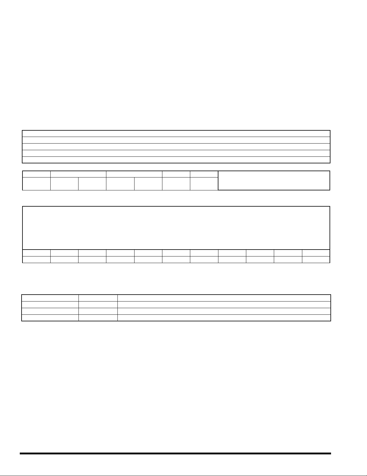
ELECTRICAL DATA
Table 9 — Electrical Data
*Permissible limits of the voltage range at which the unit will operate satisfactorily.
LEGEND
FLA - Full Load Amps
MCA - Minimum Circuit Amps
MOCP - Maximum Over-Current Protection
RLA - Rated Load Amps
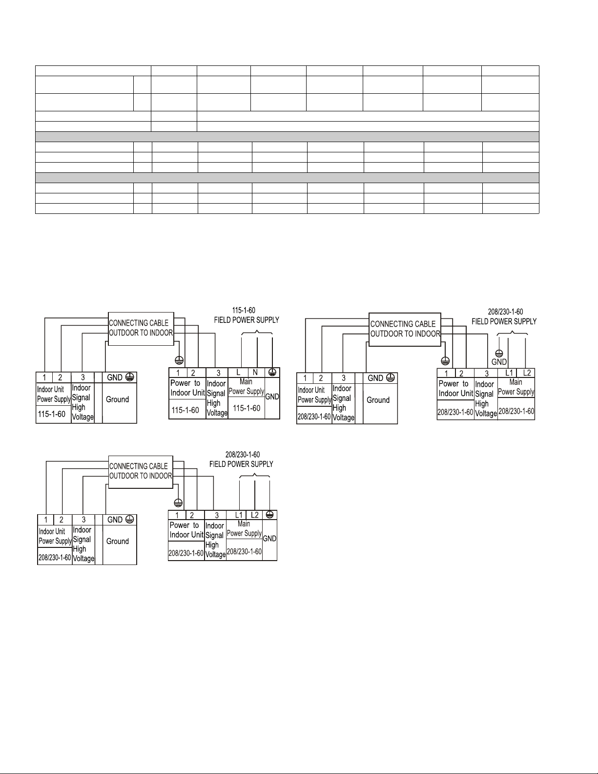
CONNECTION DIAGRAMS
Fig. 23 — Connection Diagram 12K (115V)
Fig. 24 — Connection Diagram 9K-18K (208-230V)
Fig. 25 — Connection Diagram 24K-36K (208-230V)
NOTES:
1. Do not use the thermostat wire for any connection between indoor
and outdoor units.
2. All connections between the indoor and outdoor units must be
made as shown in Figures 23 - 25. The connections are sensitive to
polarity and will result in a fault code.
Outdoor Unit 12K(115V) 9K(208/230V) 12K(208230V) 18K(208/230V) 24K(208/230V) 30K(208/230V) 36K(208/230V)
Minimum Circuit Ampacity
(MCA)
A19 15 15 16 25 23 28
Maximum Overcurrent
Protection Ampacity (MOPA)
A25 15 15 25 35 30 35
Voltage-Phase-Frequency 115-1-60 208/230-1-60
Max – Min Voltage Range 127-104 253-187
Cooling
Running Current (A) 8 2.5 3.72 6.3 8.1 11.4 18.5
Power Consumption (W) 923 556 857 1440 1845 2605 4235
Power Factor (%) 81.54 95 95.2 95 94 96.5 98.7
Heating
Running Current Range (A) 8.7 4.1 4.1 7.3 10.9 14.7 18.3
Power Consumption (W) 1000 907 907 1700 2500 3380 4200
Power Factor (%) 81.35 96.4 94.9 95 96 97.6 98.7
38MARB-01SI Specifications subject to change without notice. 17
START-UP
Test Operation
Perform a test operation after completing a gas leak and electrical
safety check. Review the indoor unit installation instructions and
owner's manual for additional start up information.
System Checks
1. Conceal the tubing where possible.
2. Ensure that the drain tube slopes downward along its entire length.
3. Ensure all tubing and connections are properly insulated.
4. Fasten the tubes to the outside wall, when possible.
5. Seal the hole through which the cables and tubing pass.
Outdoor Unit
1. Are there unusual noises or vibrations during operation?
Explain the Following Items to the Customer (with
the aid of the Owner's Manual):
2. Explain care and maintenance.
3. Present the installation instructions to the customer.
CARE AND MAINTENANCE
To help ensure high performance and minimize possible equipment
failure, periodic maintenance must be performed on this equipment.
Maintenance frequency may vary depending upon geographic areas.
TROUBLESHOOTING
For ease of service, the systems are equipped with diagnostic code
display LEDs on both the indoor and outdoor units. The outdoor
diagnostic display are two LEDs (Red and Green) on the outdoor unit
board and is limited to very few errors. The indoor diagnostic display
is a combination of flashing LEDs on the display panel or the front of
the unit.
There may be a few error codes displayed in the indoor unit that might
relate to the outdoor unit’s problems. If possible, always check the
diagnostic codes displayed on the indoor unit first. The diagnostic
codes displayed in the outdoor units are listed in Table 10.
Table 10 — Unit Diagnostic Guides
☆ = Flashing, X = Off
For additional diagnostic information, refer to the service manual.
GREEN LED RED LED FAILURE MODE
On X Standby, normal
X On Operation, normal
On On
High/Low voltage protection on
compressor terminal
On ☆ EEPROM error
X ☆ The compressor speed is out of control
☆ On
Zero-crossing signal detection error; lack
of phase; synchronization error
☆ X IGBT or Module protection
☆☆Communication error
18 Specifications subject to change without notice. 38MARB-01SI
OUTDOOR UNIT DIAGNOSTIC GUIDES
For ease of service, the systems are equipped with diagnostic code display LEDs on both the indoor and outdoor units. The outdoor diagnostic is
displayed on the outdoor unit microprocessor board.
There may be a few error codes displayed in the indoor unit that might relate to the outdoor unit's problems. If possible, always check the
diagnostic codes displayed on the indoor unit first. The diagnostic codes displayed on the outdoor units are listed on Table 10 on page 17.
Table 11 — Indoor Unit Diagnostic Codes
O (on − light) X (off − light) ☆(flash)
For additional diagnostic information, refer to the service manual.
Table 12 — Indoor Unit Functional Codes
OPERATION LAMP (TIMES) TIMER LAMP DISPLAY ERROR INFORMATION
☆1 OFF EH 00/EH 0A Indoor unit EEPROM parameter error
☆2 OFF EL 01 Indoor/outdoor unit communication error
☆3 OFF EH 02 Zero-crossing signal detection error
☆4 OFF EH 03 Indoor fan operating outside of the normal range
☆5 OFF EC 51 Outdoor unit EEPROM parameter error
☆5 OFF EC 52 T3 is in open circuit or has short circuited
☆5 OFF EC 53 T4 is in open circuit or has short circuited
☆5 OFF EC 54 TP is in open circuit or has short circuited
☆5 OFF EC 56 T2B is in open circuit or has short circuited
☆6 OFF EH 60 T1 is in open circuit or has short circuited
☆6 OFF EH 61 T2 is in open circuit or has short circuited
☆12 OFF EC 07 Outdoor fan operating outside of the normal range
☆9 OFF EH 0b Indoor PCB/Display board communication error
☆8 OFF EL 0C Refrigerant leakage detection
☆7 FLASH PC 00 IPM malfunction or IGBT OSCP
☆2 FLASH PC 01 Over voltage or over low voltage protection
☆3 FLASH PC 02 Compressor or IPM high temp/pressure protection
☆5 FLASH PC 04 Inverter compressor drive error
☆1 FLASH PC 08 Current overload protection
☆6 FLASH PC 40 Comm. error between outdoor chip and compressor chip
☆7 FLASH PC 03 Low pressure protection
☆1 ON -- Indoor units mode conflict
☆9 OFF EH b1 Indoor board and Multi-function communication error
☆11 OFF FH 0d Ionizer malfunction
DISPLAY DESCRIPTION
dF Defrost
SC Self clean
CL Filter cleaning reminder
CL Active Clean (*model dependent)
nF Filter replacement reminder
FP Heating in room temperature under 8°C
FC Forced cooling
AP AP mode of WIFI connection
CP Remote switched off
LL Remote or Wire controller Lock
On Time On
Off Time Off
E-C-O ECO mode
SD Power abnormal detection
d1 Receive DR1 signal
d2 Receive DR2 signal
d3 Receive DR3 signal
dE DR input error signal
FH 0P AP mode is activated / no WIFI kit installed
FH 0d See outdoor unit for Error Code information
EH/EC/EL/PC See outdoor unit for Error Code information
38MARB-01SI Specifications subject to change without notice. 19
Installation Data
Site Address:_______________________________________________________________________________________________________
City:________________________________________________________ State:___________ Zip Code:__________________
Installing Contractor:______________________________________________________ Contractor Contact #: ( ) _____-___________
Job Name:_______________________________________________________________ Start-up Date:_____________________________
Distributor:_______________________________________________________________
System Details
Wiring Electrical
Wire Size and Type Used? AWG:__________ TYPE:_________
Are there any breaks, splices, wire nuts or butt connectors between the outdoor unit and the indoor door unit? YES:______ NO:______
Was the wiring from the outdoor unit port to the correct indoor unit verified? YES:______ NO:______
REMARKS:_______________________________________________________________________________________________________
__________________________________________________________________________________________________________________
Voltage Check
Wiring: Single zone ___________
UNITS MODEL NO. SERIAL NO. CONTROLLER
OUTDOOR UNIT
INDOOR UNIT A
Outdoor Unit
Disconnect
1(L1):GND
Outdoor Unit
Terminal Block
1(L1):GND
NOTES:__________________________________
_________________________________________
_________________________________________
_________________________________________
_________________________________________
2(L2):GND 2(L2):GND
1(L1):L2(2) 1(L1):2(L2)
Indoor Unit
Voltage Check
@ Outdoor Unit
1(L1):GND
Indoor Unit
Voltage Check
@ Indoor Unit
1(L1):GND
NOTES:__________________________________
_________________________________________
_________________________________________
_________________________________________
_________________________________________
2(L2):GND 2(L2):GND
1(L1):2(L2) 1(L1):2(L2)
2(L2):3(S) 2(L2):3(S)
DUCTLESS START-UP CHECKLIST
Copyright 2020 CAC/BDP
D
3300 Riverwood Parkway Atlanta GA, 30339
Edition Date: 12/20 Catalog No.
38MARB-01SI
Manufacturer reserves the right to discontinue, or change at any time, specifications or designs without notice and without incurring obligations. Replaces: NEW
Ductless Start-Up Checklist (CONT)
Piping
Leak Check:
System held 500 psig (max. 550psi) for a minimum of 30 minutes using dry nitrogen. YES:______ NO:______
Evacuation Method:
•
Was the Triple Evacuation Method used as outlined in the installation manual? YES:______ NO:______
• Was the Deep Vacuum Method used as outlined in the installation manual? YES:______ NO:_______
• Did the System Hold 500 microns for 1 hour? YES:______ NO:_______
• Does the line set match the diameter of the evaporator connections? YES:______ NO:_______
• For Conventional Fan Coils, does the line set match the outdoor unit size? YES:______ NO:_______
Single Zone Piping:
Has the liquid pipe length been measured and the additional charge calculated? Size:___________ Length:_________ Charge:____________
Performance Check
Error Codes
Were there any error codes present at start-up? YES:______ NO:______
Comments:
__________________________________________________________________________________________________________________
__________________________________________________________________________________________________________________
__________________________________________________________________________________________________________________
NOTES:
PORT LIQUID SIZE SUCTION SIZE LENGTH CHARGE
NOTES:____________________________________
___________________________________________
___________________________________________
A
For 1:1 Single Zone Systems: Adjust the set-point to create an operational call for the desired testing operation. Allow the system to run for a
minimum of 10 min. and record the following details:
(Operational data recorded on applicable heads with the wireless remote controller’s Point Check function)
UNIT
SET-POINT
MODE T1 T2 T3 T4 Tb Tp Th LA/Lr
A
Indoor Unit Error Code: Notes:
Outdoor Unit Error Code:
Wall Controller:
24V Interface: