Loading ...
Loading ...
Loading ...
38MARB-01SI Specifications subject to change without notice. 15
Step 6 - Electrical Connections
Install All Power and Interconnecting Wiring to
Outdoor Units
1. Mount the outdoor power disconnect.
2. Run the power wiring from the main box to disconnect per NEC
and local codes.
3. Remove the field wiring cover from the unit by loosening the
screws.
4. Remove the caps on the conduit panel.
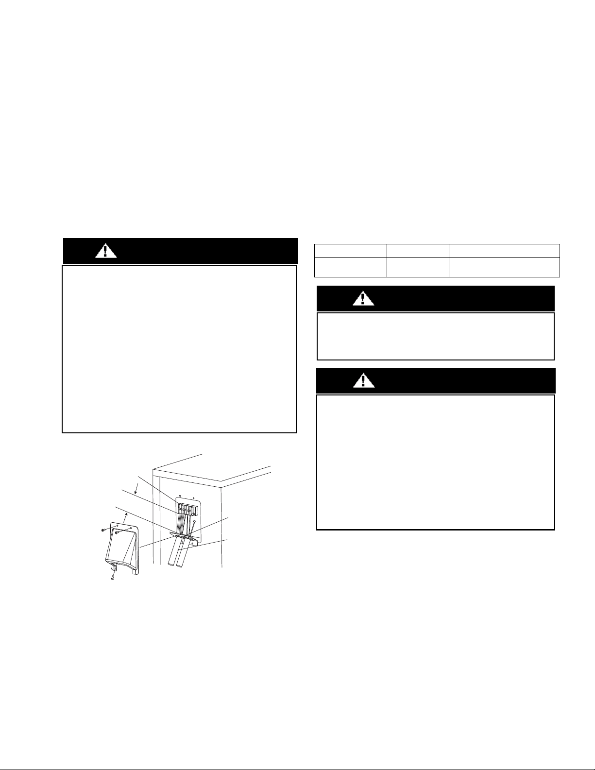
5. Connect the conduit to conduit panel (see Fig. 22).
6. Properly connect both the power supply and control lines to the
terminal block per the connection diagram for the appropriate unit
capacity and voltage.
7. Ground the unit in accordance with NEC and local electrical codes.
8. Use the lock nuts to secure the conduit.
9. Reinstall the field wiring cover.
Fig. 22 —Field Wiring
WIRING
All wires must be sized per NEC (National Electrical Code) or CEC
(Canadian Electrical Code) and local codes. Use Electrical Data table MCA
(minimum circuit amps) and MOCP (maximum over current protection) to
correctly size the wires and the disconnect fuse or breakers respectively.
Power and Communication Wiring: The main power is supplied to
the outdoor unit. The field supplied 14/3 power/communication
wiring, from the outdoor unit to the indoor unit, consists of four (4)
wires and provides the power for the indoor unit. Two wires are high
voltage AC power, one is communication wiring and the other is a
ground wire.
To minimize communication interference: If installed in a high
Electromagnetic field (EMF) area and communication issues arise, a
14/2 stranded shielded wire can be used to replace 2 (L2/N) and 3 (S)
between the outdoor and indoor units - landing the shield onto the
ground in the outdoor unit only.
Table 8 — Wiring Sizes
EQUIPMENT DAMAGE HAZARD
Failure to follow this caution may result in equipment damage or
improper operation.
Be sure to comply with local codes while running wire from
indoor unit to outdoor unit.
Every wire must be connected firmly. Loose wiring may cause the
terminal to overheat or result in unit malfunction. A fire hazard
may also exist. Therefore, ensure all wiring is tightly connected.
No wire should be allowed to touch the refrigerant tubing,
compressor or any moving parts.
Disconnecting means must be provided and shall be located
within sight and readily accessible from the air conditioner.
Connecting cable with the conduit shall be routed through hole in
the conduit panel.
CAUTION
Over 1.57" (40mm)
Terminal Block
Conduit
panel
Conduit
Outdoor unit
CABLE CABLE SIZE REMARKS
Connection Cable 14AWG
3 wire + Ground 1Φ 208/230 V
(Stranded wire is recommended)
EQUIPMENT DAMAGE HAZARD
Failure to follow this caution may result in equipment damage or
improper operation. Wires should be sized based on NEDC and
local codes.
WARNING
EQUIPMENT DAMAGE HAZARD
Failure to follow this caution may result in equipment damage or
improper operation. Be sure to comply with local codes while
running wire from the indoor unit to the outdoor unit. Every wire
must be connected firmly. Loose wiring may cause the terminal to
overheat or result in unit malfunction. A fire hazard may also exist.
Ensure all wiring is tightly connected.
No wire should touch the refrigerant tubing, compressor or any
moving parts. Disconnecting means must be provided and shall be
located within sight and readily accessible from the air conditioner.
Connecting cable with conduit shall be routed through the hole in
the conduit panel.
CAUTION
Loading ...
Loading ...
Loading ...