
Owner's Msnuel
14" Drill Press
SP-PB214
[_ WARNING!ToReduceThe RiskOfInjury,User]
L_ M_ InstructionManual.
FORSERVICECALL:@@O @O_ _@@1
PARA SERVICIO LLAME: uuu-u_umuuu&

Owner's Manual
RECOGNIZESAFETYSYMBOLS,WORDSANDLABELS
What YouNeed to KnowAboutSafetyInstructions
Warning and Important SafetyInstructionsappearingin this manualarenot meantto coverall possible
conditions and situationsthat may occur. Common sense,caution and care must be exercisedwhen
assembling or usingthis product.
Always contact your dealer, distributor, serviceagent or manufacturerabout problemsor conditions
you do not understand.
FAWARr,JiNG] Thisis a safetyalert symbol,It is usedto alertyouto potentialpersonalinjun/hazards,
Obeyall safety messagesthat follow this symbol to avoid possible injury or death,
L I_:AIITION I Thisisa safetyalertsymbol, It is usedto alertyouto potentialpersonalinjun/hazards,
Obeyall safety messagesthat follow this symbol to avoid possible injury or death,
Owner's Manual
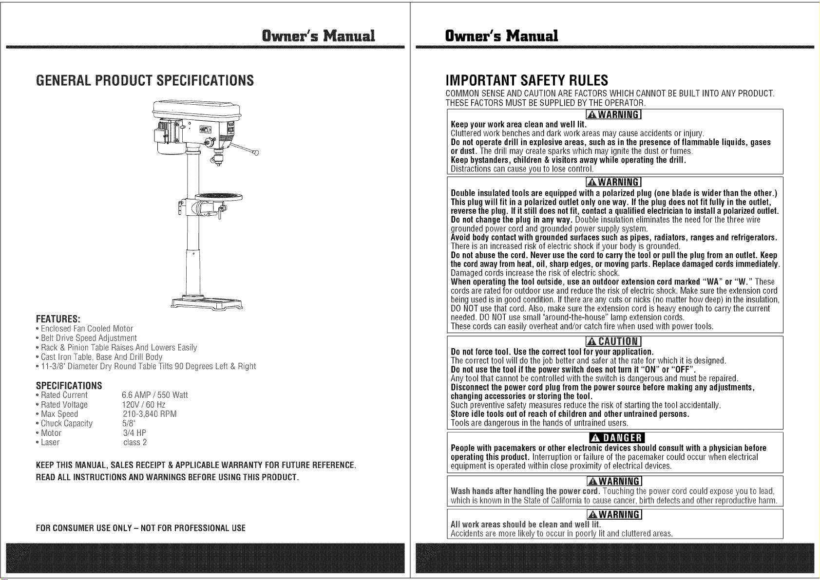
GENERALPRODUCTSPECiFiCATiONS
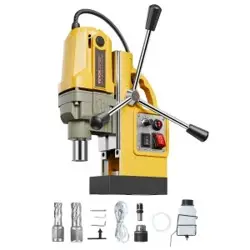
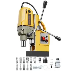
FEATURES:
o EnclosedFan CooledMotor
o BeltDrive SpeedAdiustment
o Rack& Pinion TableRaisesAnd Lowers Easily
o Cast hon Table, BaseAnd Drill Body
o !!o3/8" Diameter Dry Round TableTilts 90 DegreesLeft & Right
SPECiFiCATiONS
o RatedCurrent 6.6 AMP/ 550 Watt
o RatedVoltage !20V / BOHz
o Max Speed 210-3,840 RPM
o Chuck Capacity 5/8"
o Motor 3/4 HP
o Laser class2
KEEPTHIS MANUAL,SALESRECEIPT& APPLICABLEWARRANTYFORFUTUREREFERENCE.
READALLINSTRUCTIONSANDWARNINGSBEFOREUSINGTHIS PRODUCT.
FORCONSUMERUSEONLY- NOT FORPROFESSIONALUSE
Owner's Manual
IMPORTANTSAFETYRULES
COMMONSENSEANDCAUTIONARE FACTORSWHICHCANNOTBE BUILT INTOANY PRODUCT.
THESEFACTORSMUST BESUPPLIEDBYTHEOPERATOR.
[,_WARNINGI
Keepyourworkarea cleanand well lit.
Cluttered work benchesand dark work areasmay causeaccidents or injury.
Donot operate drill in explosiveareas, suchas in the presence of flammable liquids,gases
or dust. The drill maycreatesparks which may ignite the dust or fumes.
Keepbystanders,children& visitorsaway while operating the drill.
Distractions can causeyou to lose control.
[AWARNING]
Doubleinsulatedtoolsare equippedwitha polarizedplug(one bladeis widerthanthe other.)
This plugwill fit ina polarizedoutletonlyoneway. Ifthe plugdoesnot fit fully in theoutlet,
reversethe plug.If it stilldoesnotfit, contacta qualifiedelectricianto installa polarizedoutlet.
Donot changethe plug in anyway. Double insulation eliminatesthe needfor the three wire
grounded power cord and grounded powersupply system.
Avoidbodycontactwith groundedsurfacessuchas pipes, radiators,rangesandrefrigerators.
Thereis an increasedrisk of electricshock if your body is grounded.
Donotabusethe cord.Never usethe cordto carrythetool or pull the plug from an outlet. Keep
thecordawayfrom heat,oil, sharpedges,or movingparts. Replacedamagedcordsimmediately.
Damagedcords increasethe risk of electricshock.
Whenoperating thetool outside, use an outdoor extensioncordmarked"WA" or "W." These
cords are ratedfor outdoor useand reducethe risk of electricshock. Makesure the extensioncord
beingused is in good condition. Ifthere areany cuts or nicks (no matter how deep) inthe insulation,
DONOTuse that cord. Also, makesure the extensioncord is heavyenough to carry the current
needed.DONOTuse small "around-the-house" lamp extensioncords.
Thesecords caneasily overheatand/or catchfire when usedwith power tools.
r,a,CAUTIONI
Donot forcetool. Usethe correcttool foryourapplication.
The correct tool will do the job better and safer at the ratefor which it is designed.
Donot usethe toolif thepower switchdoesnotturn it "ON" or "OFF".
Any tool that cannotbe controlled with the switch is dangerousand must be repaired.
Disconnectthepower cordplug fromthe power sourcebeforemakingany adjustments,
changingaccessoriesorstoringthetool.
Such preventive safety measuresreducethe risk of starting the tool accidentally.
Store idle toolsout of reachof childrenand other untrainedpersons.
Tools are dangerousin the handsof untrained users.
Peoplewith pacemakers or other electronicdevicesshouldconsultwith a physician before
operatingthis product.Interruption or failure of the pacemakercould occur when electrical
equipment is operatedwithin close proximity of electrical devices.
Wash hands after handling the pewer cord. Touching the power cord could expose youto lead,
which is known in the Stateof Californiato causecancer,birth defectsandother reproductiveharm.
IAWARNING]
All werk areas shenid he cleanand well lit.
Accidents are more likely to occur in poorly fit and cluttered areas.
Owner's Manual
GENERALPRODUCTSPECiFiCATiONS
FEATURES:
o EnclosedFan CooledMotor
o BeltDrive SpeedAdiustment
o Rack& Pinion TableRaisesAnd Lowers Easily
o Cast hon Table, BaseAnd Drill Body
o !!o3/8" Diameter Dry Round TableTilts 90 DegreesLeft & Right
SPECiFiCATiONS
o RatedCurrent 6.6 AMP/ 550 Watt
o RatedVoltage !20V / BOHz
o Max Speed 210-3,840 RPM
o Chuck Capacity 5/8"
o Motor 3/4 HP
o Laser class2
KEEPTHIS MANUAL,SALESRECEIPT& APPLICABLEWARRANTYFORFUTUREREFERENCE.
READALLINSTRUCTIONSANDWARNINGSBEFOREUSINGTHIS PRODUCT.
FORCONSUMERUSEONLY- NOT FORPROFESSIONALUSE
Owner's Manual
IMPORTANTSAFETYRULES
COMMONSENSEANDCAUTIONARE FACTORSWHICHCANNOTBE BUILT INTOANY PRODUCT.
THESEFACTORSMUST BESUPPLIEDBYTHEOPERATOR.
[,_WARNINGI
Keepyourworkarea cleanand well lit.
Cluttered work benchesand dark work areasmay causeaccidents or injury.
Donot operate drill in explosiveareas, suchas in the presence of flammable liquids,gases
or dust. The drill maycreatesparks which may ignite the dust or fumes.
Keepbystanders,children& visitorsaway while operating the drill.
Distractions can causeyou to lose control.
[AWARNING]
Doubleinsulatedtoolsare equippedwitha polarizedplug(one bladeis widerthanthe other.)
This plugwill fit ina polarizedoutletonlyoneway. Ifthe plugdoesnot fit fully in theoutlet,
reversethe plug.If it stilldoesnotfit, contacta qualifiedelectricianto installa polarizedoutlet.
Donot changethe plug in anyway. Double insulation eliminatesthe needfor the three wire
grounded power cord and grounded powersupply system.
Avoidbodycontactwith groundedsurfacessuchas pipes, radiators,rangesandrefrigerators.
Thereis an increasedrisk of electricshock if your body is grounded.
Donotabusethe cord.Never usethe cordto carrythetool or pull the plug from an outlet. Keep
thecordawayfrom heat,oil, sharpedges,or movingparts. Replacedamagedcordsimmediately.
Damagedcords increasethe risk of electricshock.
Whenoperating thetool outside, use an outdoor extensioncordmarked"WA" or "W." These
cords are ratedfor outdoor useand reducethe risk of electricshock. Makesure the extensioncord
beingused is in good condition. Ifthere areany cuts or nicks (no matter how deep) inthe insulation,
DONOTuse that cord. Also, makesure the extensioncord is heavyenough to carry the current
needed.DONOTuse small "around-the-house" lamp extensioncords.
Thesecords caneasily overheatand/or catchfire when usedwith power tools.
r,a,CAUTIONI
Donot forcetool. Usethe correcttool foryourapplication.
The correct tool will do the job better and safer at the ratefor which it is designed.
Donot usethe toolif thepower switchdoesnotturn it "ON" or "OFF".
Any tool that cannotbe controlled with the switch is dangerousand must be repaired.
Disconnectthepower cordplug fromthe power sourcebeforemakingany adjustments,
changingaccessoriesorstoringthetool.
Such preventive safety measuresreducethe risk of starting the tool accidentally.
Store idle toolsout of reachof childrenand other untrainedpersons.
Tools are dangerousin the handsof untrained users.
Peoplewith pacemakers or other electronicdevicesshouldconsultwith a physician before
operatingthis product.Interruption or failure of the pacemakercould occur when electrical
equipment is operatedwithin close proximity of electrical devices.
Wash hands after handling the pewer cord. Touching the power cord could expose youto lead,
which is known in the Stateof Californiato causecancer,birth defectsandother reproductiveharm.
IAWARNING]
All werk areas shenid he cleanand well lit.
Accidents are more likely to occur in poorly fit and cluttered areas.
Owner's Manual
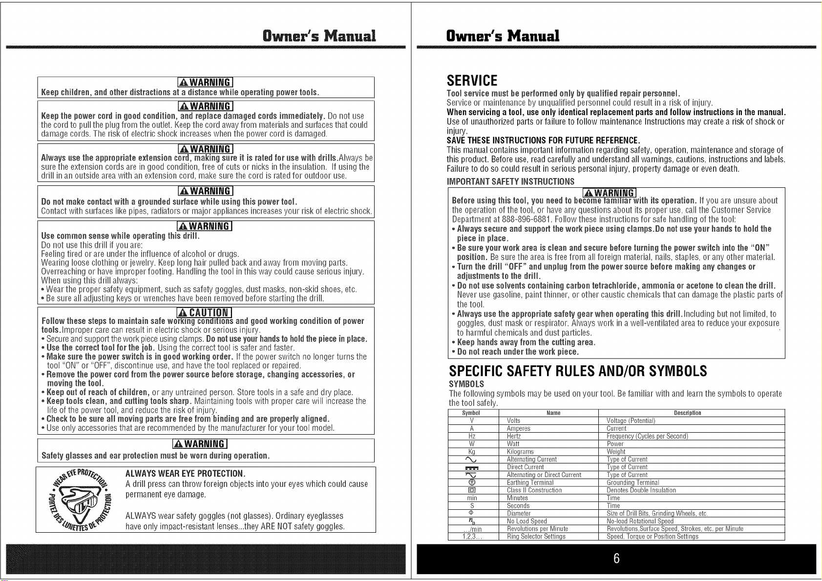
Keep chHdreo, aod other distractioos at a distaoce while operating powertools.
Keep the powercord ingood condition, and repiace damaged cords immediateiy. Donot use
thecord to pull the plugfrom the outlet, Keepthe cord awayfrom materialsandsurfacesthat could
damagecords, The risk of electric shock increaseswhen the power cord is damaged,
IAWARmNGI I
A_waysusethe appropriate exteosioo cord, making sore it is rated for rise with drills.Always beI
sure the extension cords are in good condition, free of cuts or nicks in the insulation, If usingthe
dr n anouts de areawth an extenson cord, make sure the cord s ratedfor outdoor use, J
IAWARP,ltrdGI ]
Uo netmake contact with a gronnded snrface while using this powertool.
Contactwith surfaceslike pipes, radiatorsor major appliancesincreasesyour risk of electric shock,
[AWARmNGI
Use common sense while operating this drill.
Do not usethis drill if you are:
Feelingtired or are underthe influenceof alcohol or drugs,
Wearing loose clothing or jewelry, Keeplong hair pulled backand awayfrom moving parts,
Overreachingor haveimproper footing, Handling the tool inthis way could causeserious injury,
Whenusing this drill always:
. Wearthe proper safety equipment,such as safety goggles, dust masks, non=skidshoes, etc,
. Be sure all adjusting keys or wrenches havebeenremovedbefore starting the drill,
CAUTION
Follow these steps to maintain safe goodworking ceoditieo of power
too_s.lmproper care can result in electric shock or serious injury,
. Secureandsupportthe workpieceusingclamps,Donot riseyonr handsto holdthe piece inplace.
. Usethe correct tool for the job. Usingthe correct tool is saferand faster.
* lViakesore the powerswitch is in good working order. Ifthe powerswitch no longerturns the
tool "ON" or "OFF",discontinue use,and havethe tool replaced or repaired,
* Removethe powercord from the powersonrce before storage, changing accessories, or
moving the tool.
* t(eep cot of reach of children, or any untrained person, Storetools ina safeand dry place,
. Keeptools clean, and cutting toois sharp. Maintaining tools with propercare will increasethe
life of the power tool, and reducethe risk of injury,
* Checkto be sure aHmoving pads are free from binding and are properlyaligned.
. Useonly accessoriesthat are recommendedbythe manufacturerfor your tool model,
[AWARNI_I
Safety glasses and ear protectionmost heworn doting operation.
ALWAYSWEAREYEPROTECTION.
A drill press canthrow foreign objects into your eyeswhich could cause
permanenteyedamage.
ALWAYSwearsafety goggles (not glasses).Ordinary eyeglasses
haveonly impact-resistant lenses...theyARENOTsafety goggles.
Owner's Manual
SERVICE
Toolservice most be performed only by qnalified repair personnel.
Service or maintenanceby unqualified personnelcould result in a risk of injury.
Whenservicinga tool, useonlyidentical replacementparts andfollowinstructions in themanual.
Use of unauthorizedparts or failure to follow maintenanceInstructions may createa risk of shock or
injury.
SAVETHESEINSTRUCTIONSFORFUTUREREFERENCE.
This manualcontains important information regarding safety, operation, maintenanceand storage of
this product. Beforeuse, readcarefully and understandall warnings, cautions, instructions and labels.
Failureto do so could result in serious personal injury, property damageor evendeath.
iIVIPORTANTSAFETYiNSTRUCTiONS
i i G
Before rising this tool, yon needto be ith its operation. If you are unsure about
the operationof the tool, or haveany questions about its proper use, callthe CustomerService
Departmentat 888-896-6881, Followthese instructions for safe handlingof the tool:
* Always secure aod snppod the workpiece rising clamps.go notriseyonr hands to hold the
piece in place.
* Be sore yonrwork area is cleao and secnre before tnrning the power switch into the "ON"
position. Besure the areais freefrom allforeign material, nails, staples, or any other material,
, Tornthe drill "OFF" and nnplng from the powersontce beforemaking any changes or
adjnstments to the drill.
* go notrise solvents containing carbon tetrachioride, ammonia or acetone to clean the drill.
Neverusegasoline, paintthinner, or other caustic chemicalsthat candamagethe plastic parts of
thetool,
, Always use the appropriate safety gear when operating this drill.Including but not limited, to
goggles, dust mask or respirator, Alwayswork in a weIFventilatedareato reduceyour exposure
to harmful chemicalsand dust particles,
* t(eep haodsaway from the totting area.
,, Do notreach nnder the work piece.
SPECIFICSAFETYRULESAND/ORSYMBOLS
SYI_BOLS
The following symbols may beused on your tool, Befamiliar with and learnthe symbols to operate
the tool safely,
Symbol
V
A
Hz
W
Kg
®
min
S
¢
%
.,./rain
1,2,3.,.
Name
Volts
Amperes
Hertz
Watt
Kilograms
Alternating Current
Direct Current
Alternating or Direct Current
Earthing Terminal
Class II Construction
Minutes
Seconds
Diameter
No Load Speed
Revohtions per Minute
Ring Selector Settings
Description
Voltage (Potential)
Current
Frequency (Cycles per Second)
Power
Weight
Type of Current
Type of Current
Type of Current
Grounding Terminal
Denotes Double Insulation
Time
Time
Size of Drill Bits, Grinding Wheels, etc,
No-load Rotational Speed
Revohtions,Surface Speed, Strokes, etc. per Minute
Speed, Torque or Position Settings
Owner's Manual
Keep chHdreo, aod other distractioos at a distaoce while operating powertools.
Keep the powercord ingood condition, and repiace damaged cords immediateiy. Donot use
thecord to pull the plugfrom the outlet, Keepthe cord awayfrom materialsandsurfacesthat could
damagecords, The risk of electric shock increaseswhen the power cord is damaged,
IAWARmNGI I
A_waysusethe appropriate exteosioo cord, making sore it is rated for rise with drills.Always beI
sure the extension cords are in good condition, free of cuts or nicks in the insulation, If usingthe
dr n anouts de areawth an extenson cord, make sure the cord s ratedfor outdoor use, J
IAWARP,ltrdGI ]
Uo netmake contact with a gronnded snrface while using this powertool.
Contactwith surfaceslike pipes, radiatorsor major appliancesincreasesyour risk of electric shock,
[AWARmNGI
Use common sense while operating this drill.
Do not usethis drill if you are:
Feelingtired or are underthe influenceof alcohol or drugs,
Wearing loose clothing or jewelry, Keeplong hair pulled backand awayfrom moving parts,
Overreachingor haveimproper footing, Handling the tool inthis way could causeserious injury,
Whenusing this drill always:
. Wearthe proper safety equipment,such as safety goggles, dust masks, non=skidshoes, etc,
. Be sure all adjusting keys or wrenches havebeenremovedbefore starting the drill,
CAUTION
Follow these steps to maintain safe goodworking ceoditieo of power
too_s.lmproper care can result in electric shock or serious injury,
. Secureandsupportthe workpieceusingclamps,Donot riseyonr handsto holdthe piece inplace.
. Usethe correct tool for the job. Usingthe correct tool is saferand faster.
* lViakesore the powerswitch is in good working order. Ifthe powerswitch no longerturns the
tool "ON" or "OFF",discontinue use,and havethe tool replaced or repaired,
* Removethe powercord from the powersonrce before storage, changing accessories, or
moving the tool.
* t(eep cot of reach of children, or any untrained person, Storetools ina safeand dry place,
. Keeptools clean, and cutting toois sharp. Maintaining tools with propercare will increasethe
life of the power tool, and reducethe risk of injury,
* Checkto be sure aHmoving pads are free from binding and are properlyaligned.
. Useonly accessoriesthat are recommendedbythe manufacturerfor your tool model,
[AWARNI_I
Safety glasses and ear protectionmost heworn doting operation.
ALWAYSWEAREYEPROTECTION.
A drill press canthrow foreign objects into your eyeswhich could cause
permanenteyedamage.
ALWAYSwearsafety goggles (not glasses).Ordinary eyeglasses
haveonly impact-resistant lenses...theyARENOTsafety goggles.
Owner's Manual
SERVICE
Toolservice most be performed only by qnalified repair personnel.
Service or maintenanceby unqualified personnelcould result in a risk of injury.
Whenservicinga tool, useonlyidentical replacementparts andfollowinstructions in themanual.
Use of unauthorizedparts or failure to follow maintenanceInstructions may createa risk of shock or
injury.
SAVETHESEINSTRUCTIONSFORFUTUREREFERENCE.
This manualcontains important information regarding safety, operation, maintenanceand storage of
this product. Beforeuse, readcarefully and understandall warnings, cautions, instructions and labels.
Failureto do so could result in serious personal injury, property damageor evendeath.
iIVIPORTANTSAFETYiNSTRUCTiONS
i i G
Before rising this tool, yon needto be ith its operation. If you are unsure about
the operationof the tool, or haveany questions about its proper use, callthe CustomerService
Departmentat 888-896-6881, Followthese instructions for safe handlingof the tool:
* Always secure aod snppod the workpiece rising clamps.go notriseyonr hands to hold the
piece in place.
* Be sore yonrwork area is cleao and secnre before tnrning the power switch into the "ON"
position. Besure the areais freefrom allforeign material, nails, staples, or any other material,
, Tornthe drill "OFF" and nnplng from the powersontce beforemaking any changes or
adjnstments to the drill.
* go notrise solvents containing carbon tetrachioride, ammonia or acetone to clean the drill.
Neverusegasoline, paintthinner, or other caustic chemicalsthat candamagethe plastic parts of
thetool,
, Always use the appropriate safety gear when operating this drill.Including but not limited, to
goggles, dust mask or respirator, Alwayswork in a weIFventilatedareato reduceyour exposure
to harmful chemicalsand dust particles,
* t(eep haodsaway from the totting area.
,, Do notreach nnder the work piece.
SPECIFICSAFETYRULESAND/ORSYMBOLS
SYI_BOLS
The following symbols may beused on your tool, Befamiliar with and learnthe symbols to operate
the tool safely,
Symbol
V
A
Hz
W
Kg
®
min
S
¢
%
.,./rain
1,2,3.,.
Name
Volts
Amperes
Hertz
Watt
Kilograms
Alternating Current
Direct Current
Alternating or Direct Current
Earthing Terminal
Class II Construction
Minutes
Seconds
Diameter
No Load Speed
Revohtions per Minute
Ring Selector Settings
Description
Voltage (Potential)
Current
Frequency (Cycles per Second)
Power
Weight
Type of Current
Type of Current
Type of Current
Grounding Terminal
Denotes Double Insulation
Time
Time
Size of Drill Bits, Grinding Wheels, etc,
No-load Rotational Speed
Revohtions,Surface Speed, Strokes, etc. per Minute
Speed, Torque or Position Settings
8_.er's Ma.ual
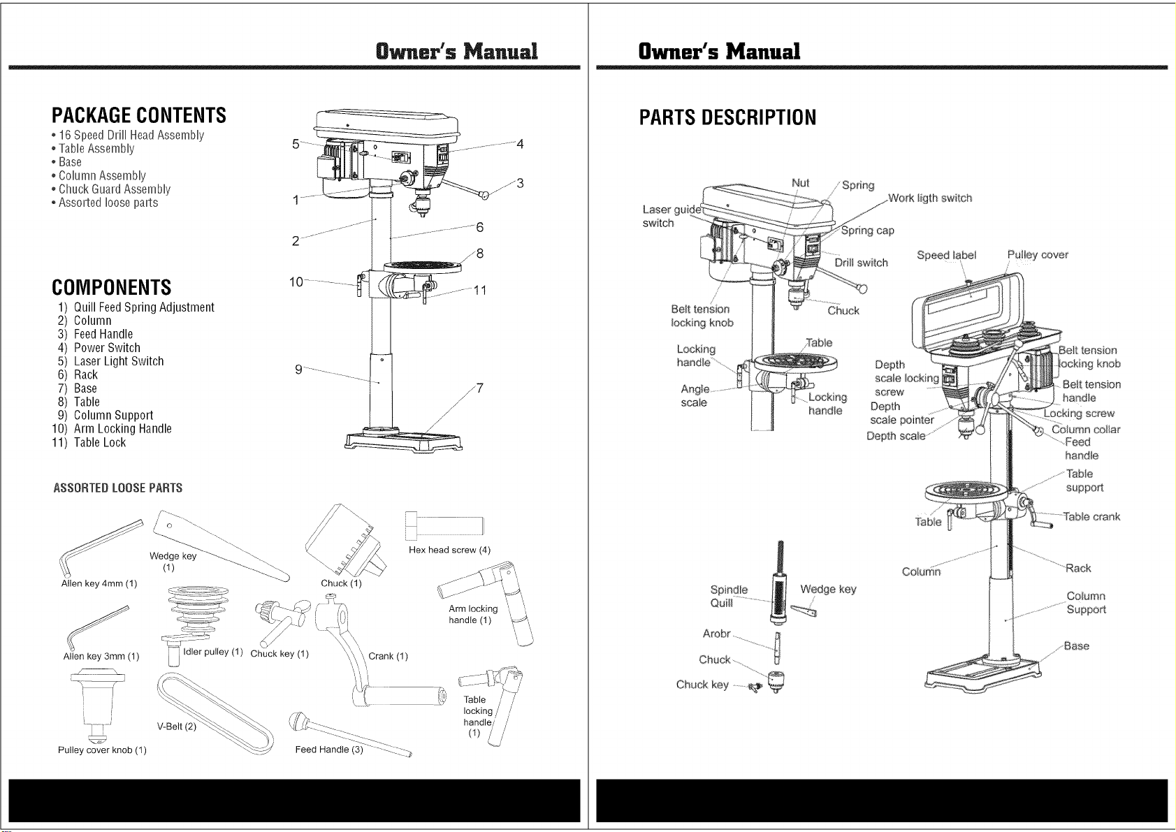
PACKAGECONTENTS
* 16 SpeedDrH[HeadAssemNy
° TaNeAssemNy
* Base
° ConumnAssemNy
° Chuck GuardAssemNy
* Assorted nooseparts
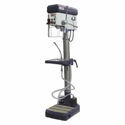
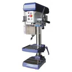
COMPONENTS
1
2
3
4
5
6
7
8
9
10
11
Quill FeedSpring Adjustment
Column
FeedHandle
Power Switch
LaserLight Switch
Rack
Base
Table
Column Support
Arm Locking Handle
TableLock
ASSORTEDLOOSEPARTS
Allen key 4mm (1)
Allen key 3mm (1)
Wedge key
(1)
V-Belt (2)
r
Pulley cover knob (1)
Chuck key (1)
Chuck (1)
'\/Crank (1)
IIIIIIIIIIIII ZZI/
Hex head screw (4)
Arm locking
handle (1) _'/
handle/ /
(1) _.j/
Owner's Manual
PARTSDESCRIPTION
Laser gui
switch
//
Belt tension
locking knob
Locking
haedle............
scaie
Chuck key .......
Nut
handie
ligth switch
Ddli switch Speed _abe_ Pulley cover
Chuck
Depth
screw
Depth
Depth
Column
tension
kr_ob
Be_t tensfon
handie
n9 screw"
Column col_a_
".Feed
handle
Co,urns

8_.er's Ma.ual
PACKAGECONTENTS
* 16 SpeedDrH[HeadAssemNy
° TaNeAssemNy
* Base
° ConumnAssemNy
° Chuck GuardAssemNy
* Assorted nooseparts
COMPONENTS
1
2
3
4
5
6
7
8
9
10
11
Quill FeedSpring Adjustment
Column
FeedHandle
Power Switch
LaserLight Switch
Rack
Base
Table
Column Support
Arm Locking Handle
TableLock
ASSORTEDLOOSEPARTS
Allen key 4mm (1)
Allen key 3mm (1)
Wedge key
(1)
V-Belt (2)
r
Pulley cover knob (1)
Chuck key (1)
Chuck (1)
'\/Crank (1)
IIIIIIIIIIIII ZZI/
Hex head screw (4)
Arm locking
handle (1) _'/
handle/ /
(1) _.j/
Owner's Manual
PARTSDESCRIPTION
Laser gui
switch
//
Belt tension
locking knob
Locking
haedle............
scaie
Chuck key .......
Nut
handie
ligth switch
Ddli switch Speed _abe_ Pulley cover
Chuck
Depth
screw
Depth
Depth
Column
tension
kr_ob
Be_t tensfon
handie
n9 screw"
Column col_a_
".Feed
handle
Co,urns

Owner's Manual
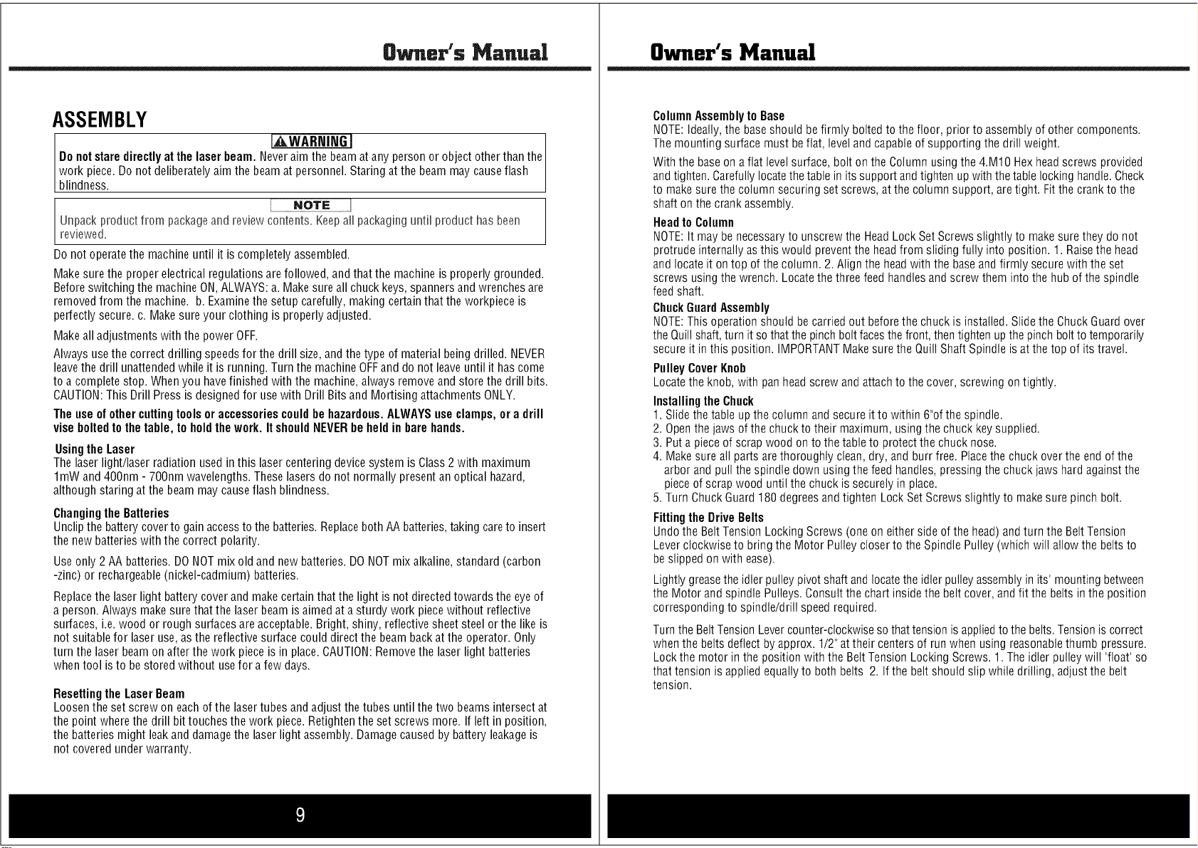
ASSEMBLY
I
Donotstaredirectlyat the laserbeam. Neveraim the beamat any personor object other thanthe
work piece.Do not deliberatelyaimthe beam at personnel.Staring at the beam maycauseflash
b ndness.
NOTE 1
Unpackproduct from packageand review contents. Keepannpackaginguntil product hasbeen
reviewed.
Donot operatethe machineuntil it is completelyassembled.
Makesure the properelectrical regulationsare followed, and that the machineis properly grounded.
Beforeswitching the machineON,ALWAYS:a. Makesure all chuckkeys, spannersand wrenchesare
removedfrom the machine, b. Examinethe setup carefully, making certainthat the workpiece is
perfectlysecure,c. Makesure your clothing is properlyadjusted.
Makeall adjustmentswith the power OFF.
Always usethe correct drilling speedsfor the drill size, andthe type of material being drilled. NEVER
leavethe drill unattendedwhile it is running. Turn the machineOFFand do not leaveuntil it has come
to a completestop. Whenyou havefinished with the machine,always removeand store the drill bits.
CAUTION:This Drill Pressis designedfor usewith Drill Bits and Mortising attachments ONLY.
The use of othercuttingtools oraccessoriescouldbe hazardous.ALWAYSuse clamps, ora drill
vise boltedto the table, to holdthework. ItshouldNEVERbe held in barehands.
Usingthe Laser
The laserlight/laser radiation used inthis lasercentering devicesystem is Class2 with maximum
1roWand 40Onto- 70Ontowavelengths.Theselasers do not normally presentan optical hazard,
although staring atthe beam maycauseflash blindness.
Changingthe Batteries
Unclipthe batterycoverto gainaccessto the batteries.Replaceboth AA batteries,taking careto insert
the new batterieswith the correct polarity.
Useonly 2 AA batteries.DONOT mix old and new batteries. DONOTmix alkaline,standard (carbon
-zinc) or rechargeable(nickel-cadmium) batteries.
Replacethe laserlight battery cover and makecertainthat the light is not directedtowards the eyeof
a person. Alwaysmake sure that the laserbeam isaimed at a sturdy work piecewithout reflective
surfaces, i.e. wood or rough surfacesare acceptable.Bright, shiny, reflectivesheet steelor the like is
not suitablefor laser use,as the reflectivesurface could direct the beambackat the operator. Only
turn the laser beamon after the work pieceis in place. CAUTION:Removethe laser light batteries
when tool is to be stored without use for a few days.
Resetting the Laser Beam
Loosenthe set screw on eachof the lasertubes andadjust the tubes until the two beamsintersect at
the point where the drill bit touchesthe work piece.Retightenthe set screws more. If left in position,
the batteries might leakand damagethe laserlight assembly. Damagecaused by battery leakageis
not coveredunder warranty.
Owner's Manual
ColumnAssemblyto Base
NOTE:Ideally,the baseshould befirmly bolted to the floor, prior to assemblyof other components.
The mounting surface must be flat, leveland capableof supporting the drill weight.
With the baseon a flat level surface, bolt onthe Column usingthe 4M10 Hex headscrews provided
and tighten. Carefullylocatethetable in its supportandtighten up with thetable locking handle.Check
to makesure the columnsecuring set screws,at the column support, are tight. Fitthe crank to the
shaft onthe crank assembly.
Headto Column
NOTE:tt may benecessaryto unscrewthe HeadLockSet Screwsslightly to makesure they do not
protrude internallyas this would preventthe headfrom sliding fully into position. 1. Raisethe head
and locateit ontop of the column. 2. Alignthe headwith the baseand firmly securewith the set
screws usingthe wrench. Locatethe threefeed handlesand screw them into the hub of the spindle
feed shaft.
ChuckGuardAssembly
NOTE:This operation should be carried out beforethe chuck is installed.Slidethe ChuckGuardover
the Quillshaft, turn it so that the pinchbolt facesthe front, thentighten upthe pinch boltto temporarily
secureit inthis position. IMPORTANTMakesure the QuillShaft Spindle is at the top of its travel.
PulleyCoverKnob
Locatethe knob, with pan headscrew and attach to the cover, screwing on tightly.
Installingthe Chuck
1. Slidethe table up the column and secureit to within 6"of the spindle.
2. Openthe jaws of the chuckto their maximum, usingthe chuckkey supplied.
3. Puta pieceof scrap wood on to the table to protect the chuck nose.
4. Makesure all parts arethoroughly clean,dry, and burr free. Placethe chuck over the end of the
arbor and pull the spindle down using the feed handles,pressingthe chuckjaws hard againstthe
pieceof scrapwood until the chuck is securelyin place.
5. Turn ChuckGuard 180 degreesand tighten Lock SetScrews slightly to makesure pinch bolt.
Fittingthe DriveBelts
Undothe BeltTension Locking Screws (one on eitherside of the head)and turn the BeltTension
Leverclockwiseto bringthe Motor Pulleycloser to the SpindlePulley (which will allow the belts to
beslipped on with ease).
Lightly greasethe idler pulleypivot shaftand locatethe idler pulley assemblyin its' mounting between
the Motor and spindle Pulleys.Consultthe chart insidethe belt cover, and fit the belts in the position
correspondingto spindle/drill speed required.
Turn the BeltTensionLevercounter-clockwiseso thattension is appliedto the belts.Tensionis correct
when the belts deflect by approx. 1/2" at their centers of run when using reasonablethumb pressure.
Lockthe motor in the position with the Belt Tension Locking Screws. 1. The idler pulley will 'float' so
that tension is applied equallyto both belts 2. If the belt should slip while drilling, adjustthe belt
tension.

Owner's Manual
ASSEMBLY
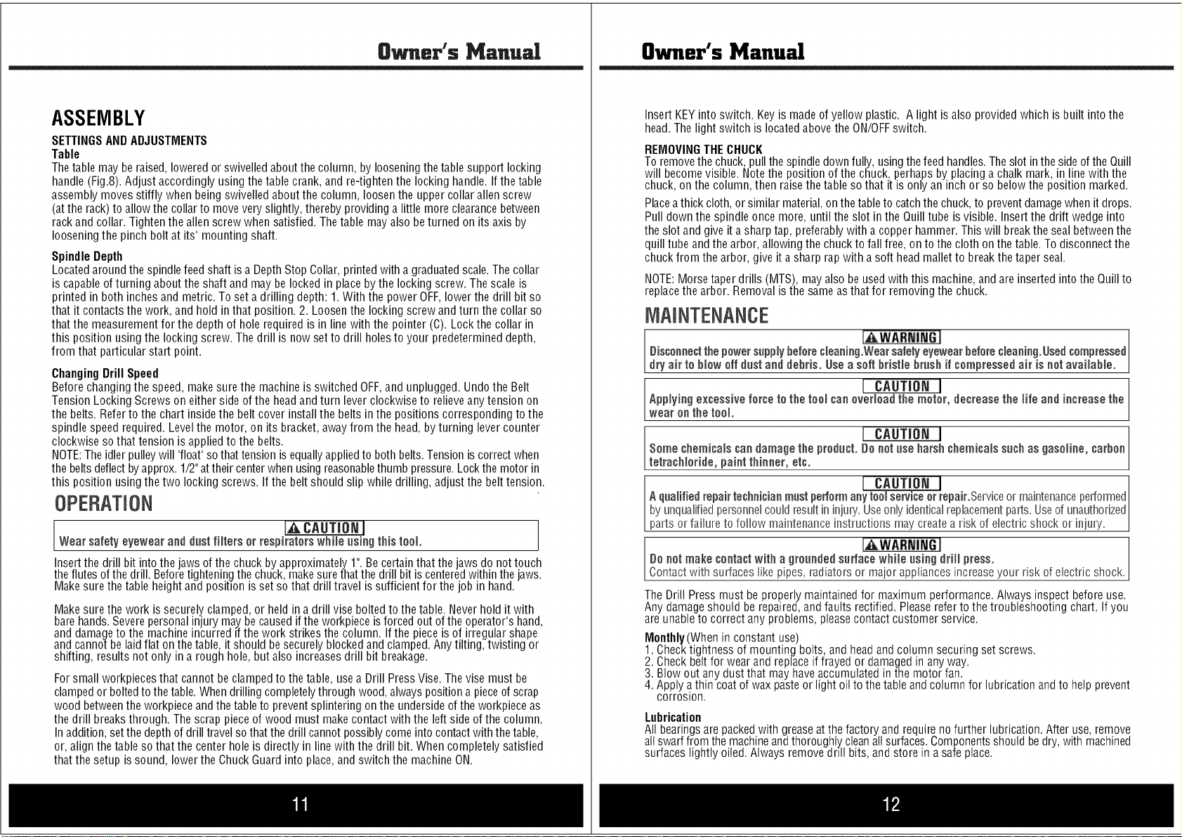
SETTINGSANDADJUSTMENTS
Table
The table maybe raised,loweredor swivelledaboutthe column, by looseningthetable support locking
handle(Fig.8). Adjust accordingly using the table crank, and re-tighten the locking handle. If the table
assembly movesstiffly when being swivelledabout the column, loosen the uppercollar allen screw
(at the rack) to allowthe collarto move veryslightly, thereby providing a little more clearancebetween
rackand collar. Tightenthe allen screwwhen satisfied. The table may alsobe turned on its axis by
looseningthe pinch bolt at its' mountingshaft.
SpindleDepth
Locatedaroundthe spindle feedshaft is a Depth Stop Collar,printedwith a graduatedscale.The collar
is capableof turning about the shaft and maybe lockedin placeby the locking screw. The scale is
printed in both inchesand metric.To set a drilling depth: 1. With the power OFF,lowerthe drill bit so
that it contacts the work, and hold in that position. 2. Loosenthe locking screw andturn the collar so
that the measurementfor the depth of hole required is in line with the pointer (C). Lockthe collar in
this position usingthe locking screw. Thedrill is now set to drill holesto your predetermineddepth,
from that particular start point.
ChangingDrill Speed
Beforechanging the speed,make sure the machine is switched OFF,and unplugged. Undothe Belt
Tension Locking Screwson either side of the headand turn leverclockwise to relieveany tension on
the belts. Referto the chart inside the belt cover install the beltsin the positions corresponding to the
spindle speed required. Levelthe motor, on its bracket,away from the head,by turning levercounter
clockwiseso that tension is applied to the belts.
NOTE:The idlerpulleywill 'float' sothat tension is equallyappliedto both belts.Tensionis correct when
the beltsdeflectby approx.1/2" attheir centerwhenusing reasonablethumb pressure.Lockthe motor in
this position usingthe two locking screws. If the belt should slip while drilling, adjust the belttension.
OPERATION
J,_ CAUTION I
Wear safety eyewear and dust filters or respirators while using this tool.
Insertthe drill bit into the jaws of the chuck by approximately 1".Be certain that the jaws do not touch
theflutes ofthe drill. Beforetighteningthe chuck,makesure that the drill bit is centeredwithin the jaws.
Makesure the table height and position is set so that drill travel is sufficient for the job in hand.
Makesure the work issecurely clamped, or held in a drill vise boltedto the table. Neverhold it with
barehands.Severepersonalinjury may.be causedif the workpieceis forced out of the operator's hand,
and damageto the machineincurred if the work strikes the column. If the pieceis of irregular shape
and cannotbe laidflat on thetable, it should besecurely blocked and clamped.Any tilting, twisting or
shifting, results not only ina rough hole, but also increasesdrill bit breakage.
Forsmall workpiecesthat cannot beclampedto the table, usea Drill PressVise. The vise must be
clampedor boltedto thetable. Whendrilling completelythrough wood,always positiona pieceof scrap
wood betweenthe workpieceandthe table to preventsplintering on the undersideof the workpieceas
the drill breaksthrough. The scrap pieceof wood must makecontact with the left side of the column.
In addition,set thedepth of drill travelso that the drill cannot possiblycome into contactwith the table,
or, align the table so that the center hole is directly in line with the drill bit. Whencompletely satisfied
that the setup is sound, lowerthe ChuckGuard into place,and switch the machineON.
Owner's Manual
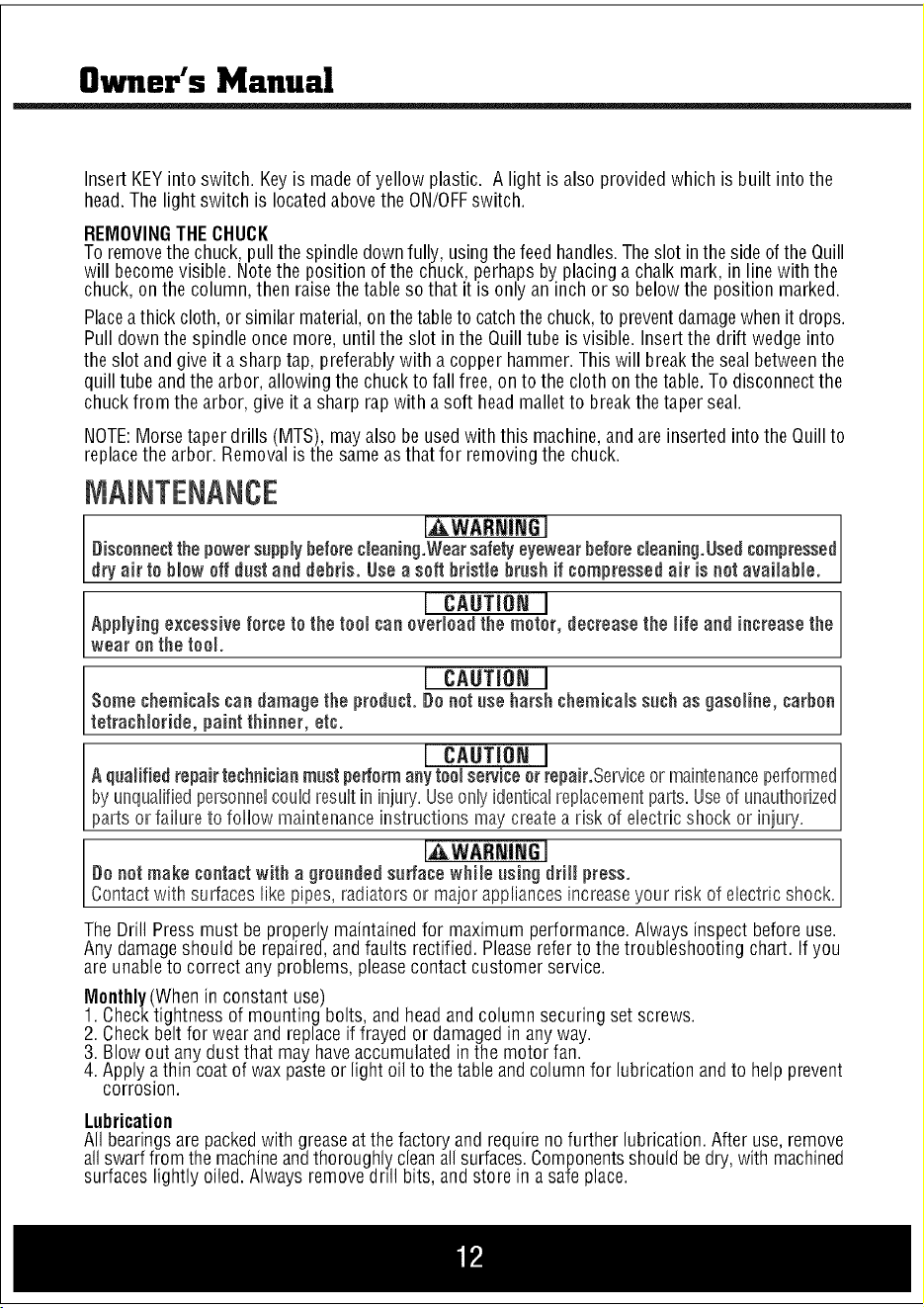
Insert KEYinto switch. Key is madeof yellow plastic. A light isalso provided which is built into the
head.The light switch is locatedabovethe ON/OFFswitch.
REMOVINGTHECHUCK
To removethe chuck,pull the spindledownfully, usingthefeed handles.Theslot inthe sideof the Quill
will becomevisible. Notethe position of the chuck,perhaps by placinga chalk mark, in linewith the
chuck, onthe column,then raisethe table so that it is only an inch or so belowthe position marked.
Placeathick cloth,or similar material,on thetableto catchthe chuck,to preventdamagewhenit drops.
Pull down the spindle once more, until the slot in the Quilltube is visible. Insertthe drift wedge into
the slot and give it a sharp tap, preferablywith a copper hammer.This will breakthe sealbetweenthe
quill tube and the arbor, allowingthe chuckto fall free,on to the cloth onthe table.To disconnectthe
chuckfrom the arbor, give it a sharp rap with a soft head mallet to breakthe taper seal.
NOTE:Morsetaper drills (MTS), mayalso be usedwith this machine,and are inserted intothe Quillto
replacethe arbor. Removalis the sameas that for removingthe chuck.
[AWASNIN6 I
Disconnectthe powersupplybeforecleaning.Wearsafelyeyewearbeforecleaning.Usedcompressed
dry air to blow off dust and debris. Usea soft bristle brush if compressed air is not available.
Applying excessive force I CAUTION I
to the tool can overload the motor, decreasethe life and increase the
wear on the too.
Some chemicals candamagethe I CAUTION I
product. De oatuse harshchemicals such as gasoline, carbon
tetrach or de, pa at th ooer, etc.
I CAUTIONI
A qualified repair technicianmost periormany tool service orrepair.Serviceor maintenanceperformed
by unquafifiedpersonnencoundresuntin injury'.Useonnyidenticalreplacementparts.Useof unauthorized
parts or fa ure to fo ow ma ntenance nstruct ons maycreatea r sk of e ectr c shock or n ury.
I_WARNiNG I
Do not make contactwith a groooded so#ace while osing drill press.
Contact with surfaceslike pipes, radiators or major appliancesincreaseyour risk of electric shock.
The Drill Press must be properly maintainedfor maximum performance.Always inspect before use.
Any damageshould be repaired,and faults rectified. Pleaserefer to the troubleshooting chart. If you
are unableto correct any problems, pleasecontact customer service.
Monthly(When in constant use)
1. Checktightness of mounting bolts, and headand column securing set screws.
2. Checkbeltfor wear and replaceif frayed or damagedin anyway.
3. Blow out any dustthat may haveaccumulated inthe motor fan.
4. Apply athin coatof wax pasteor light oil to the tableand columnfor lubricationandto help prevent
corrosion.
Lubrication
All bearingsare packedwith greaseat the factory and requireno further lubrication.After use, remove
allswarffrom the machineandthoroughly,cleanallsurfaces.Componentsshould bedry,with machined
surfaces lightly oiled. Always remove doll bits, and store in a safe place.
Owner's Manual
ASSEMBLY
SETTINGSANDADJUSTMENTS
Table
The table maybe raised,loweredor swivelledaboutthe column, by looseningthetable support locking
handle(Fig.8). Adjust accordingly using the table crank, and re-tighten the locking handle. If the table
assembly movesstiffly when being swivelledabout the column, loosen the uppercollar allen screw
(at the rack) to allowthe collarto move veryslightly, thereby providing a little more clearancebetween
rackand collar. Tightenthe allen screwwhen satisfied. The table may alsobe turned on its axis by
looseningthe pinch bolt at its' mountingshaft.
SpindleDepth
Locatedaroundthe spindle feedshaft is a Depth Stop Collar,printedwith a graduatedscale.The collar
is capableof turning about the shaft and maybe lockedin placeby the locking screw. The scale is
printed in both inchesand metric.To set a drilling depth: 1. With the power OFF,lowerthe drill bit so
that it contacts the work, and hold in that position. 2. Loosenthe locking screw andturn the collar so
that the measurementfor the depth of hole required is in line with the pointer (C). Lockthe collar in
this position usingthe locking screw. Thedrill is now set to drill holesto your predetermineddepth,
from that particular start point.
ChangingDrill Speed
Beforechanging the speed,make sure the machine is switched OFF,and unplugged. Undothe Belt
Tension Locking Screwson either side of the headand turn leverclockwise to relieveany tension on
the belts. Referto the chart inside the belt cover install the beltsin the positions corresponding to the
spindle speed required. Levelthe motor, on its bracket,away from the head,by turning levercounter
clockwiseso that tension is applied to the belts.
NOTE:The idlerpulleywill 'float' sothat tension is equallyappliedto both belts.Tensionis correct when
the beltsdeflectby approx.1/2" attheir centerwhenusing reasonablethumb pressure.Lockthe motor in
this position usingthe two locking screws. If the belt should slip while drilling, adjust the belttension.
OPERATION
J,_ CAUTION I
Wear safety eyewear and dust filters or respirators while using this tool.
Insertthe drill bit into the jaws of the chuck by approximately 1".Be certain that the jaws do not touch
theflutes ofthe drill. Beforetighteningthe chuck,makesure that the drill bit is centeredwithin the jaws.
Makesure the table height and position is set so that drill travel is sufficient for the job in hand.
Makesure the work issecurely clamped, or held in a drill vise boltedto the table. Neverhold it with
barehands.Severepersonalinjury may.be causedif the workpieceis forced out of the operator's hand,
and damageto the machineincurred if the work strikes the column. If the pieceis of irregular shape
and cannotbe laidflat on thetable, it should besecurely blocked and clamped.Any tilting, twisting or
shifting, results not only ina rough hole, but also increasesdrill bit breakage.
Forsmall workpiecesthat cannot beclampedto the table, usea Drill PressVise. The vise must be
clampedor boltedto thetable. Whendrilling completelythrough wood,always positiona pieceof scrap
wood betweenthe workpieceandthe table to preventsplintering on the undersideof the workpieceas
the drill breaksthrough. The scrap pieceof wood must makecontact with the left side of the column.
In addition,set thedepth of drill travelso that the drill cannot possiblycome into contactwith the table,
or, align the table so that the center hole is directly in line with the drill bit. Whencompletely satisfied
that the setup is sound, lowerthe ChuckGuard into place,and switch the machineON.
Owner's Manual
Insert KEYinto switch. Key is madeof yellow plastic. A light isalso provided which is built into the
head.The light switch is locatedabovethe ON/OFFswitch.
REMOVINGTHECHUCK
To removethe chuck,pull the spindledownfully, usingthefeed handles.Theslot inthe sideof the Quill
will becomevisible. Notethe position of the chuck,perhaps by placinga chalk mark, in linewith the
chuck, onthe column,then raisethe table so that it is only an inch or so belowthe position marked.
Placeathick cloth,or similar material,on thetableto catchthe chuck,to preventdamagewhenit drops.
Pull down the spindle once more, until the slot in the Quilltube is visible. Insertthe drift wedge into
the slot and give it a sharp tap, preferablywith a copper hammer.This will breakthe sealbetweenthe
quill tube and the arbor, allowingthe chuckto fall free,on to the cloth onthe table.To disconnectthe
chuckfrom the arbor, give it a sharp rap with a soft head mallet to breakthe taper seal.
NOTE:Morsetaper drills (MTS), mayalso be usedwith this machine,and are inserted intothe Quillto
replacethe arbor. Removalis the sameas that for removingthe chuck.
[AWASNIN6 I
Disconnectthe powersupplybeforecleaning.Wearsafelyeyewearbeforecleaning.Usedcompressed
dry air to blow off dust and debris. Usea soft bristle brush if compressed air is not available.
Applying excessive force I CAUTION I
to the tool can overload the motor, decreasethe life and increase the
wear on the too.
Some chemicals candamagethe I CAUTION I
product. De oatuse harshchemicals such as gasoline, carbon
tetrach or de, pa at th ooer, etc.
I CAUTIONI
A qualified repair technicianmost periormany tool service orrepair.Serviceor maintenanceperformed
by unquafifiedpersonnencoundresuntin injury'.Useonnyidenticalreplacementparts.Useof unauthorized
parts or fa ure to fo ow ma ntenance nstruct ons maycreatea r sk of e ectr c shock or n ury.
I_WARNiNG I
Do not make contactwith a groooded so#ace while osing drill press.
Contact with surfaceslike pipes, radiators or major appliancesincreaseyour risk of electric shock.
The Drill Press must be properly maintainedfor maximum performance.Always inspect before use.
Any damageshould be repaired,and faults rectified. Pleaserefer to the troubleshooting chart. If you
are unableto correct any problems, pleasecontact customer service.
Monthly(When in constant use)
1. Checktightness of mounting bolts, and headand column securing set screws.
2. Checkbeltfor wear and replaceif frayed or damagedin anyway.
3. Blow out any dustthat may haveaccumulated inthe motor fan.
4. Apply athin coatof wax pasteor light oil to the tableand columnfor lubricationandto help prevent
corrosion.
Lubrication
All bearingsare packedwith greaseat the factory and requireno further lubrication.After use, remove
allswarffrom the machineandthoroughly,cleanallsurfaces.Componentsshould bedry,with machined
surfaces lightly oiled. Always remove doll bits, and store in a safe place.

Owner's Manual
ACCESSORIES
Use only accessories that are recommended by the manufacturer for your modeL Accessoriesthat
may besuitaNe for oneteenmay become hazardouswhen usedon another tool
Always attach grounded (3-prong) extension cordste grounded(3=ptoag)outlets.
ifyou must use an exteasien cord, hesure that the gauge is large enoughto carrythe ameunt of
current necessaryfor your power teal nfnot, your teenmay experiencea loss of power, excessive
voltage drop or overheating,Forexample,the smaller the gaugenumber, the heavierthe cord,
TROUBLESHOOTING
Noisy? Reviewthe probablecauseand remedy:
A) Incorrect belt tension A) Adjust tension operation
B) Dry spindle B) Removespindle/ quill assemblyand lubricate
C) Loosepulley lubricate C)Tighten Pulley
D) Worn bearing D) Replacebearing
Excessivedrill wobble? Reviewthe probablecauseand remedy:
A) Loose chuck A) Tighten by pressing chuck down onto a block of
wood against the table.
B) Worn spindle or bearing B) Replacespindle shaft or bearing
C) Worn chuck C) Replacechuck
D) Bentdrill bit D) Replacedrill bit
Motor won't start? Reviewthe probablecauseand remedy:
A) Power supply A) Checkpower cord/fuse start
B) Motor connection B) Checkmotor connections
C) NVRswitch connections C) Checkswitch connections
D) FaultySwitch D) Replaceswitch
E) Motor Windings Burned E)ReplaceMotor
Drill Bit Bindsin Workpiece?Reviewthe probablecauseand remedy:
A) ExcessiveFeedPressure A) Apply less pressure
B) LooseBelt B) CheckBelt tension
C) LooseDrill Bit C)Tighten drill bit with key
D) Incorrect drill speed D) Referto Cutting Speedchart, and adjust drill speed accordingly
Table difficult to raise? Reviewthe probablecauseand remedy:
A) Needslubrication A) Lubricate with light oil
B) Tablelocktightened B) Loosenclamp
Owner's Manual
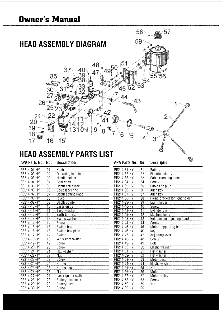
HEADASSEMBLYDIAGRAM
9
/ 55 56
HEADASSEMBLYPARTSLIST
APAParts No. No. Description APAParts No. No. Description
PB214-O1-HY 01 Knob PB214-31-HY 31 Battery
PB214-O2-HY 02 0eperatinsIhandle PB214-32-HY 32 Electric_
PB214-O3-HY 03 Handle holder PB214-33-HY 33 Cableclami#!Egplate
PB214-O4-HY 04 Gearshaft PB214-34-HY 34 Screw
PB214-O5-HY 05 Depth scale label PB214-35-HY 35 Cableand plug
PB214-O6-HY 06 Scale label ring PB214-36-HY 36 Allen key
PB214-O7-HY 07 De_ knob PB214-37-HY 37 Allen key
PB214-O8-HY 08 Rivet PB214-38-HY 38 Fixing bracket for light holder
PB214-O9-HY 09 Depth pointer PB214-39-HY 39 Light holder
PB214-10-HY 10 Laser guide PB214-40-HY 40 Screw
PB214-11-HY 11 Teethwasher PB214-41-HY 41 Cylinder pin
PB214-12-HY 12 Earthterminal PB214-42-HY 42 Machine body
PB214-13-HY 13 Elastic washer PB214-43-HY 43 Belttension adjusting handle
PB214-14-HY 14 Screw PB214-44-HY 44 Screw
PB214-15-HY 15 Switch box PB214-45-HY 45 Motors@porting bar
PB214-16-HY 16 Switch boxplate PB214-46-HY 46
PB214-17-HY 17 Switch PB214-47-HY 47 _lever
PB214-18-HY 18 Work light switch PB214-48-HY 48 Screw
PB214-19-HY 19 Screw PB214-49-HY 49 Bolt
PB214-20-HY 20 Screw PB214-50-HY 50 Elastic washer
PB214-21-HY 21 Flat washer PB214-51-HY 51 Flat washer
PB214-22-HY 22 Nut PB214-52-HY 52 Flat washer
PB214-23-HY 23 Screw PB214-53-HY 53 Motor base
PB214-24-HY 24 Spring PB214-54-HY 54 Elastic washer
PB214-25-HY 25 Spring cap PB214-55-HY 55 Nut
PB214-26-HY 26 Nut PB214-56-HY 56 Motor
PB214-27-HY 27 Laser guider switch PB214-57-HY 57 Motor pulley
PB214-28-HY 28 Battery box cover PB214-58-HY 58 Screw
PB214-29-HY 29 Battery box PB214-59-HY 59 Nut
PB214-30-HY 30 Screw PB214-60-HY 60
Owner's Manual
ACCESSORIES
Use only accessories that are recommended by the manufacturer for your modeL Accessoriesthat
may besuitaNe for oneteenmay become hazardouswhen usedon another tool
Always attach grounded (3-prong) extension cordste grounded(3=ptoag)outlets.
ifyou must use an exteasien cord, hesure that the gauge is large enoughto carrythe ameunt of
current necessaryfor your power teal nfnot, your teenmay experiencea loss of power, excessive
voltage drop or overheating,Forexample,the smaller the gaugenumber, the heavierthe cord,
TROUBLESHOOTING
Noisy? Reviewthe probablecauseand remedy:
A) Incorrect belt tension A) Adjust tension operation
B) Dry spindle B) Removespindle/ quill assemblyand lubricate
C) Loosepulley lubricate C)Tighten Pulley
D) Worn bearing D) Replacebearing
Excessivedrill wobble? Reviewthe probablecauseand remedy:
A) Loose chuck A) Tighten by pressing chuck down onto a block of
wood against the table.
B) Worn spindle or bearing B) Replacespindle shaft or bearing
C) Worn chuck C) Replacechuck
D) Bentdrill bit D) Replacedrill bit
Motor won't start? Reviewthe probablecauseand remedy:
A) Power supply A) Checkpower cord/fuse start
B) Motor connection B) Checkmotor connections
C) NVRswitch connections C) Checkswitch connections
D) FaultySwitch D) Replaceswitch
E) Motor Windings Burned E)ReplaceMotor
Drill Bit Bindsin Workpiece?Reviewthe probablecauseand remedy:
A) ExcessiveFeedPressure A) Apply less pressure
B) LooseBelt B) CheckBelt tension
C) LooseDrill Bit C)Tighten drill bit with key
D) Incorrect drill speed D) Referto Cutting Speedchart, and adjust drill speed accordingly
Table difficult to raise? Reviewthe probablecauseand remedy:
A) Needslubrication A) Lubricate with light oil
B) Tablelocktightened B) Loosenclamp
Owner's Manual
HEADASSEMBLYDIAGRAM
9
/ 55 56
HEADASSEMBLYPARTSLIST
APAParts No. No. Description APAParts No. No. Description
PB214-O1-HY 01 Knob PB214-31-HY 31 Battery
PB214-O2-HY 02 0eperatinsIhandle PB214-32-HY 32 Electric_
PB214-O3-HY 03 Handle holder PB214-33-HY 33 Cableclami#!Egplate
PB214-O4-HY 04 Gearshaft PB214-34-HY 34 Screw
PB214-O5-HY 05 Depth scale label PB214-35-HY 35 Cableand plug
PB214-O6-HY 06 Scale label ring PB214-36-HY 36 Allen key
PB214-O7-HY 07 De_ knob PB214-37-HY 37 Allen key
PB214-O8-HY 08 Rivet PB214-38-HY 38 Fixing bracket for light holder
PB214-O9-HY 09 Depth pointer PB214-39-HY 39 Light holder
PB214-10-HY 10 Laser guide PB214-40-HY 40 Screw
PB214-11-HY 11 Teethwasher PB214-41-HY 41 Cylinder pin
PB214-12-HY 12 Earthterminal PB214-42-HY 42 Machine body
PB214-13-HY 13 Elastic washer PB214-43-HY 43 Belttension adjusting handle
PB214-14-HY 14 Screw PB214-44-HY 44 Screw
PB214-15-HY 15 Switch box PB214-45-HY 45 Motors@porting bar
PB214-16-HY 16 Switch boxplate PB214-46-HY 46
PB214-17-HY 17 Switch PB214-47-HY 47 _lever
PB214-18-HY 18 Work light switch PB214-48-HY 48 Screw
PB214-19-HY 19 Screw PB214-49-HY 49 Bolt
PB214-20-HY 20 Screw PB214-50-HY 50 Elastic washer
PB214-21-HY 21 Flat washer PB214-51-HY 51 Flat washer
PB214-22-HY 22 Nut PB214-52-HY 52 Flat washer
PB214-23-HY 23 Screw PB214-53-HY 53 Motor base
PB214-24-HY 24 Spring PB214-54-HY 54 Elastic washer
PB214-25-HY 25 Spring cap PB214-55-HY 55 Nut
PB214-26-HY 26 Nut PB214-56-HY 56 Motor
PB214-27-HY 27 Laser guider switch PB214-57-HY 57 Motor pulley
PB214-28-HY 28 Battery box cover PB214-58-HY 58 Screw
PB214-29-HY 29 Battery box PB214-59-HY 59 Nut
PB214-30-HY 30 Screw PB214-60-HY 60
8wner's Manual
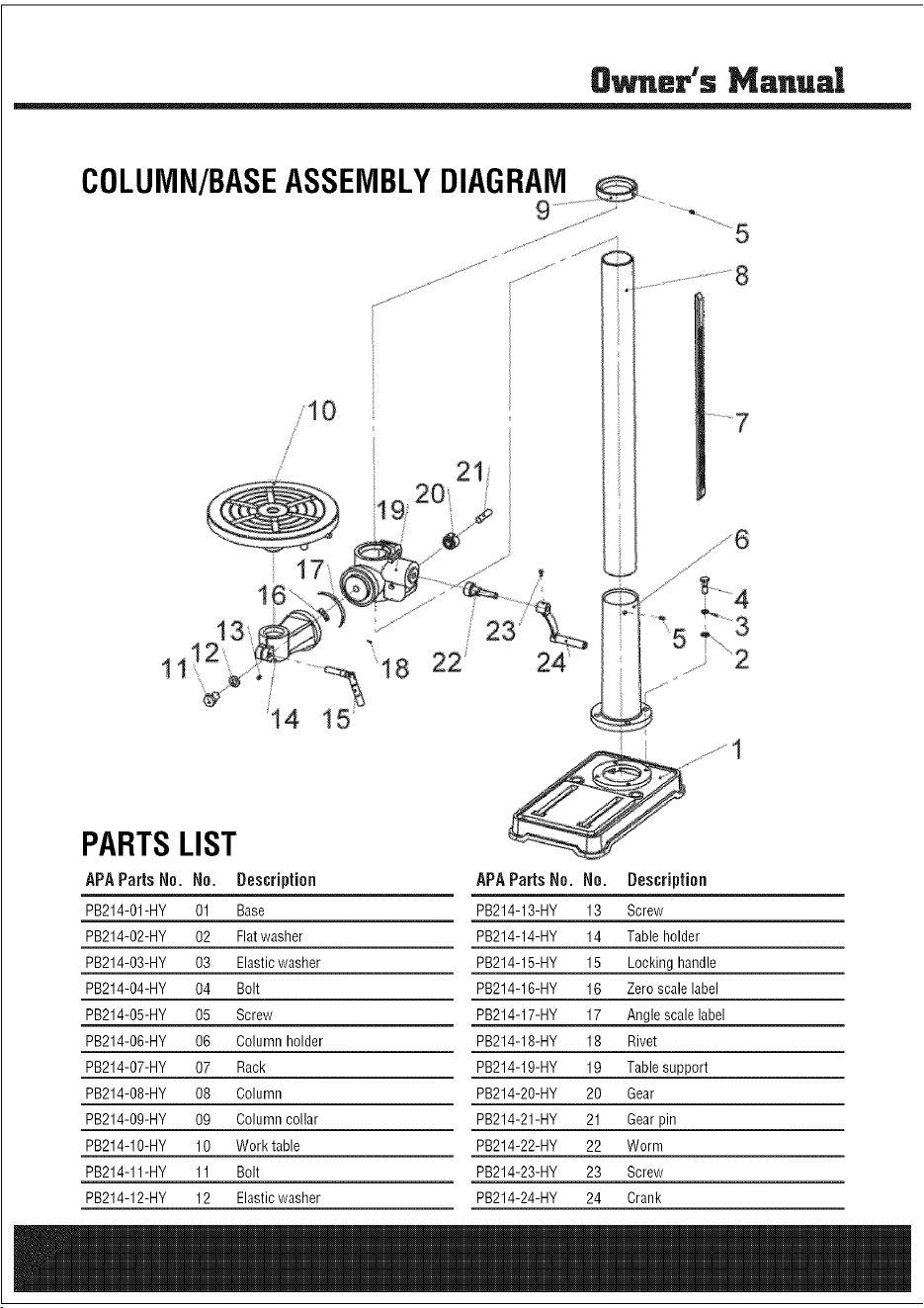
PARTSLIST
APAParts No. No. Description APAParts No. No. Description
PB214-O1-HY 01 Base PB214-13-HY 13 Screw
PB214-O2-HY 02 Flatwasher PB214-14-HY 14 Table holder
PB214-O3-HY 03 Elasticwasher PB214-15-HY 15 Locking handle
PB214-O4-HY 04 Bolt PB214-16-HY 16 Zero scale label
PB214-O5-HY 05 Screw PB214-17-HY 17 Angle scale label
PB214-O6-HY 06 Column holder PB214-18-HY 18 Rivet
PB214-O7-HY 07 Rack PB214-19-HY 19 Table support
PB214-O8-HY 08 Column PB214-20-HY 20 Gear
PB214-O9-HY 09 Column collar PB214-21-HY 21 Gearpin
PB214-10-HY 10 Work table PB214-22-HY 22 Worm
PB214-11-HY 11 Bolt PB214-23-HY 23 Screw
PB214-12-HY 12 Elasticwasher PB214-24-HY 24 Crank
Owner's Manual
PULLEYANDSPINDLEASSEMBLYDIAGRAM
22..........
24 ......................÷
PULLEY
APA Parts Ne.
PB214-O1-HY
PB214-O2-HY
PB214-O3-HY
PB214-O4-HY
PB214-O5-HY
PB214-O6-HY
PB214-O7-HY
PB214-O8-HY
PB214-O9-HY
PB214-10-HY
PB214-12-HY
PB214-11-HY
PB214-13-HY
PB214-14-HY
PB214-15-HY
PB214-16-HY
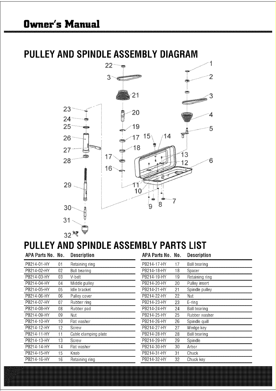
ANDSPINDLEASSEMBLYPARTSLIST
No. Description APAParts No. No. Description
01 Retaining ring PB214-17-HY 17 Ball bearing
02 Ball bearing PB214-18-HY 18 Spacer
03 V-belt PB214-19-HY 19 Retaining ring
04 Middle pulley PB214-20-HY 20 Pulley insert
05 Idle bracket PB214-21-HY 21 Spindle pulley
06 Pulley cover PB214-22-HY 22 Nut
07 Rubber ring PB214-23-HY 23 E-ring
08 Rubber pad PB214-24-HY 24 Ball bearing
09 Nut PB214-25-HY 25 Rubber washer
10 Flatwasher PB214-26-HY 26 Spindle quill
12 Screw PB214-27-HY 27 Wedge key
11 Cableclamping plate PB214-28-HY 28 Ball bearing
13 Screw PB214-29-HY 29 Spindle
14 Flatwasher PB214-30-HY 30 Arbor
15 Knob PB214-31-HY 31 Chuck
16 Retaining ring PB214-32-HY 32 Chuck key
8wner's Manual
PARTSLIST
APAParts No. No. Description APAParts No. No. Description
PB214-O1-HY 01 Base PB214-13-HY 13 Screw
PB214-O2-HY 02 Flatwasher PB214-14-HY 14 Table holder
PB214-O3-HY 03 Elasticwasher PB214-15-HY 15 Locking handle
PB214-O4-HY 04 Bolt PB214-16-HY 16 Zero scale label
PB214-O5-HY 05 Screw PB214-17-HY 17 Angle scale label
PB214-O6-HY 06 Column holder PB214-18-HY 18 Rivet
PB214-O7-HY 07 Rack PB214-19-HY 19 Table support
PB214-O8-HY 08 Column PB214-20-HY 20 Gear
PB214-O9-HY 09 Column collar PB214-21-HY 21 Gearpin
PB214-10-HY 10 Work table PB214-22-HY 22 Worm
PB214-11-HY 11 Bolt PB214-23-HY 23 Screw
PB214-12-HY 12 Elasticwasher PB214-24-HY 24 Crank
Owner's Manual
PULLEYANDSPINDLEASSEMBLYDIAGRAM
22..........
24 ......................÷
PULLEY
APA Parts Ne.
PB214-O1-HY
PB214-O2-HY
PB214-O3-HY
PB214-O4-HY
PB214-O5-HY
PB214-O6-HY
PB214-O7-HY
PB214-O8-HY
PB214-O9-HY
PB214-10-HY
PB214-12-HY
PB214-11-HY
PB214-13-HY
PB214-14-HY
PB214-15-HY
PB214-16-HY
ANDSPINDLEASSEMBLYPARTSLIST
No. Description APAParts No. No. Description
01 Retaining ring PB214-17-HY 17 Ball bearing
02 Ball bearing PB214-18-HY 18 Spacer
03 V-belt PB214-19-HY 19 Retaining ring
04 Middle pulley PB214-20-HY 20 Pulley insert
05 Idle bracket PB214-21-HY 21 Spindle pulley
06 Pulley cover PB214-22-HY 22 Nut
07 Rubber ring PB214-23-HY 23 E-ring
08 Rubber pad PB214-24-HY 24 Ball bearing
09 Nut PB214-25-HY 25 Rubber washer
10 Flatwasher PB214-26-HY 26 Spindle quill
12 Screw PB214-27-HY 27 Wedge key
11 Cableclamping plate PB214-28-HY 28 Ball bearing
13 Screw PB214-29-HY 29 Spindle
14 Flatwasher PB214-30-HY 30 Arbor
15 Knob PB214-31-HY 31 Chuck
16 Retaining ring PB214-32-HY 32 Chuck key

Owner's Manusl
_ted Warranty
Steele@warrants to the original purchaser who uses the product in a consumer application (personal,
residential or household usage) that all products covered under this warranty are free from defects in
material and workmanship for one year from the date of purchase. All products covered by this limited
warranty which are used in commercial applications (i.e. income producing) are warranted to be free of
defects in material and workmanship for 90 days from the date of original purchase. Products covered under
this warranty include air compressors, tools, service parts, pressure washers and generators.
Steele@will repair or replace, at Steele@'s sole option, products or components which have failed within the
warranty period. Service will be scheduled according to the normal work flow and business hours at the
service center location, and the availability of replacement parts. All decisions of Steele@ with regard to this
limited warranty shall be final.
This warranty gives you specific legal rights, and you may also have other rights which vary from state to
state.
RESPONSIBILITYOFORIGINALPURCHASER(initial User):
Toprocessa warrantyclaim onthis product,DONOTreturn itemto the retailer.The product mustbe
evaluatedby an AuthorizedWarrantyServiceCenter.Forthelocation of the nearestAuthorizedWarranty
ServiceCentercontact the retaileror placeof purchase.
Retain original cash register sales receipt as proof of purchase for warranty to work.
Use reasonable care in the operation and maintenance of the product as described in the Owner's Manual(s).
Deliver or ship the product to the Authorized Warranty Service Center. Freight costs, if any must be paid by
the purchaser. If the purchaser does not receive satisfactory results form the Authorized Warranty Service
Center, the purchaser should contact Steele@ toll free 888-896-6881.
THIS WARRANTY DOES NOT COVER:
Merchandise sold as reconditioned, used as rental equipment, or floor or display models.
Merchandise that has become damaged or inoperative because of ordinary wear, misuse, cold, heat, rain,
excessive humidity, freeze damage, use of improper chemicals, negligence, accident, failure to operate the
product in accordance with the instructions provided in the Owner's Manual(s) supplied with the product,
improper maintenance, the use of accessories or attachments not recommended by Steele@, or
unauthorized repair or alterations.
. Repair and transportation costs of merchandise determine not to be defective.
. Costs associated with assembly, required oil, adjustments or other installation and start-up costs.
Expendable parts or accessories supplied with the product which are expected to become inoperative or
unusable after a reasonable period of use.

Owner's Manual
Merchandise sold by Steele@ which has been manufactured by and identified as the product of another
company, such as gasoline engines. The product manufacturer's warranty, if any, will apply.
ANY INCIDENTAL, INDIRECT OR CONSEQUENTIALLOSS, DAMAGE, OR EXPENSETHAT MAY RESULT
FROM ANY DEFECTS,FAILURE OR MALFUNCTION OF THE PRODUCT IS NOT COVERED BY THIS
WARRANTY. Some states do not allow the exclusion, so it may not apply to you.
IMPLIED WARRANTIES, INCLUDING THOSE OF MERCHANTABILITY OR FITNESS FOR A PARTICULAR
PURPOSE, ARE LIMITED TO ONEYEAR FROM THE DATE OF ORIGINAL PURCHASE. Some states do not
allow limitations on how long an implied warranty lasts, so the above limitations may not apply to you.
Distributed by:
730 S.EppersonDr.
City Of Industry,CA91748
www.steele-products.com
all rights reserved