
US
Bench drilling machine
Operating Manual
Version 2.1.8
Upright drilling machine
B 24 H (13" Item No. 53UG96)
B 28 HB (16" Item No. 53UG97)
B 28 H (16" Item No. 53UG98)
B 28 HV (16" Item No. 53UG99)

Page 2
B24H | B28H | B28HB | B28HVUS
Table of contents
1 Safety
1.1 Safety warnings (warning notes) ..............................................................................................................6
1.1.1 Classification of hazards...........................................................................................................................6
1.1.2 Other pictograms ......................................................................................................................................7
1.2 Proper use ................................................................................................................................................8
1.3 Possible dangers caused by the bench drill and upright drill....................................................................8
1.4 Qualification of employees........................................................................................................................9
1.4.1 Target group .............................................................................................................................................9
1.4.2 Authorized persons...................................................................................................................................9
1.5 Safety measures during operation..........................................................................................................10
1.6 Safety devices ........................................................................................................................................10
1.7 Safety check ...........................................................................................................................................11
1.8 EMERGENCY-STOP button...................................................................................................................12
1.9 Drilling table ............................................................................................................................................12
1.10 Separating protective devices.................................................................................................................13
1.10.1 Protective cover of the belt pulleys.........................................................................................................13
1.10.2 Drill chuck guard.....................................................................................................................................13
1.11 Personal protective equipment ...............................................................................................................13
1.12 Safety during operation...........................................................................................................................14
1.13 Safety during maintenance.....................................................................................................................14
1.13.1 Switching-off and securing the bench drill and upright drill.....................................................................14
1.14 Use of lifting equipments ........................................................................................................................15
1.14.1 Mechanical maintenance work ...............................................................................................................15
1.15 Accident report........................................................................................................................................15
1.16 Electrical .................................................................................................................................................15
2 Technical Data
2.1 Power connection ...................................................................................................................................16
2.2 Drilling capacity.......................................................................................................................................16
2.3 Spindle....................................................................................................................................................16
2.4 Drilling machine table .............................................................................................................................16
2.9 Emissions ...............................................................................................................................................17
2.5 Required space.......................................................................................................................................17
2.6 Speeds....................................................................................................................................................17
2.7 Environmental conditions........................................................................................................................17
2.8 Operating material ..................................................................................................................................17
2.10 Dimensions B24H...................................................................................................................................19
2.11 Dimensions B28HB.................................................................................................................................20
2.12 Dimensions B28H...................................................................................................................................21
2.13 Dimensions B28HV.................................................................................................................................22
3 Assembly
3.1 Scope of delivery ....................................................................................................................................23
3.2 Transport ................................................................................................................................................23
3.3 Storage ...................................................................................................................................................24
3.4 Installation and assembly .......................................................................................................................25
3.4.1 Site requirements....................................................................................................................................25
3.4.2 Assembly ................................................................................................................................................26
3.4.3 Assembly of the drilling machine table B24H (B28H B)..........................................................................27
3.4.4 Assembly of the drilling machine table B28H (Vario)..............................................................................27
3.5 Installation...............................................................................................................................................29
3.5.1 Mounting.................................................................................................................................................30
3.5.2 Installation drawings ...............................................................................................................................31

Page 3
B24H | B28H | B28HB | B28HV US
3.6 First use ................................................................................................................................................ 33
4Operation
4.1 Safety ..................................................................................................................................................... 34
4.2 Control and indicating elements............................................................................................................. 34
4.2.1 Drilling machine B24H | B28 HB.............................................................................................................34
4.2.2 Drilling machine B28H | B28HV.............................................................................................................35
4.2.3 Control panel B24H ................................................................................................................................36
4.2.4 Control panel B28H (Vario), B28HB....................................................................................................... 36
4.3 Turn the machine on B24H / B28H / B28HB .......................................................................................... 38
4.4 Turn the machine on B28HV.................................................................................................................. 38
4.5 Turn the machine off B24H / B28H / B28HB.......................................................................................... 38
4.6 Turn the machine off´B28H Vario...........................................................................................................38
4.7 Speed variation ......................................................................................................................................39
4.7.1 Speed table B24H ..................................................................................................................................40
4.7.2 Speed table B28H - B28HB....................................................................................................................40
4.7.3 Speed table B28HV................................................................................................................................41
4.8 Drill depth stop .......................................................................................................................................41
4.9 Removing, mounting of drill chucks and drills ........................................................................................42
4.9.1 Keyless drill chuck..................................................................................................................................42
4.9.2 Removing the drill chuck ........................................................................................................................42
4.9.3 Removing the tool or drill chuck with the integrated drill drift on the B28H (B, Vario) ............................43
4.9.4 Mounting the drill chuck B24H and B28H (B, Vario) ..............................................................................43
4.10 Cooling ...................................................................................................................................................44
4.11 Before starting the working process.......................................................................................................45
4.12 During the working process....................................................................................................................45
5 Determining the cutting speed and the speed
5.1 Table cutting speeds / infeed .................................................................................................................46
5.2 Speed table ............................................................................................................................................ 46
5.3 Examples to calculatory determine the required speed for your drilling machine ..................................48
6 Maintenance
6.1 Safety ..................................................................................................................................................... 50
6.1.1 Preparation.............................................................................................................................................50
6.1.2 Restarting............................................................................................................................................... 50
6.2 Inspection and maintenance .................................................................................................................. 50
6.3 Repair.....................................................................................................................................................53
7 Spare parts - B24H | B28H | B28HB | B28HV
7.1 B24H ...................................................................................................................................................... 54
7.1.1 Drilling head B24H ................................................................................................................................. 54
7.1.2 Column and drilling table B24H.............................................................................................................. 55
7.1.3 Pulleys B24H.......................................................................................................................................... 56
7.1.4 Parts list B24H........................................................................................................................................56
7.1.5 Wiring diagram B24H - 115V, 60 Hz ......................................................................................................59
7.2 B28H | B28HB ........................................................................................................................................ 60
7.2.1 Drilling head B28H | B28HB ...................................................................................................................60
7.2.2 Column and drilling table B28H.............................................................................................................. 61
7.2.3 Column and drilling table B28HB ...........................................................................................................62
7.2.4 Pulleys B28H | B28HB............................................................................................................................63
7.2.5 Parts list B28H | B28HB ......................................................................................................................... 64
7.3 B28HV.................................................................................................................................................... 67
7.3.1 Drilling head B28HV............................................................................................................................... 67
7.4 Column and drilling table B28HV ...........................................................................................................68
7.4.1 Pulleys B28HV .......................................................................................................................................69
7.4.2 Parts list B28HV .....................................................................................................................................70
7.4.3 Wiring diagram B28H | B28HB - 115V, 60Hz......................................................................................... 73

Page 4
B24H | B28H | B28HB | B28HVUS
7.4.4 Wiring diagram B28HV, page 1 - 230V, 60Hz ........................................................................................74
7.4.5 Wiring diagram B28HV, page 2 - 230V, 60Hz ........................................................................................75
8 Troubleshooting
9 Appendix
9.1 Copyright ................................................................................................................................................78
9.2 Terminology/Glossary.............................................................................................................................78
Preface
Dear customer,
Thank you very much for purchasing a product made by company.
Company metal working machines offer a maximum of quality, technically company solutions and convince
by an outstanding price performance ratio. Continuous enhancements and product innovations guarantee
state-of-the-art products and safety at any time.
Before commissioning the machine please thoroughly read these operating instructions and get familiar with
the machine. Please also make sure that all persons operating the machine have read and understood the
operating instructions beforehand.
Keep these operating instructions in a safe place nearby the machine.
Information
The operating instructions include indications for safety-relevant and proper installation, operation and main-
tenance of the machine. The continuous observance of all notes included in this manual guarantee the safety
of persons and of the machine.
The manual determines the intended use of the machine and includes all necessary information for its eco-
nomic operation as well as its long service life.
In the paragraph "Maintenance" all maintenance works and functional tests are described which the operator
must perform in regular intervals.
The illustration and information included in the present manual can possibly deviate from the current state of
construction of your machine. Being the manufacturer we are continuously seeking for improvements and
renewal of the products. Therefore, changes might be performed without prior notice. The illustrations of the
machine may be different from the illustrations in these instructions with regard to a few details. However,
this does not have any influence on the operability of the machine.
Therefore, no claims may be derived from the indications and descriptions. Changes and errors are reserved!
Your suggestion with regard to these operating instructions are an important contribution to optimising our
work which we offer to our customers. For any questions or suggestions for improvement, please do not hesi-
tate to contact us.
If you have any further questions after reading these operating instructions and you are not able to
solve your problem with a help of these operating instructions, please contact your specialised
dealer or
C.H.HANSON
2000 North Aurora Rd.
Naperville,IL 60563
Call 800-827-3398

Page 5
B24H | B28H | B28HB | B28HV US
1 Safety
Glossary of symbols
This part of the operating manual
does explain the meaning and how to use the warning references contained in this operat-
ing manual,
does explain how to use the bench and upright drilling machine,
highlights the dangers that might arise for you and others if these instructions are not fol-
lowed thoroughly,
informs you on how to prevent dangers.
In addition to this operating manual, please note
applicable laws and regulations,
legal regulations for preventing an accident,
the prohibition, warning and mandatory signs as well as the warning notes on the bench
drilling machine.
Consult OSHA, state and local regulations in order to determine compliance, danger and risks to
the operator.
ALWAYS KEEP THIS DOCUMENT CLOSE TO THE BENCH DRILL AND UPRIGHT DRILL
FOR FUTURE REFERENCE.
INFORMATION
If you are unable to solve a problem using this manual, please contact us for advice:
Exclusive USA
Agent
C.H.HANSON
2000 North Aurora Rd.
Naperville,IL 60563
Call 800-827-3398
gives further advice
calls on you to get in action
enumeration

Page 6
B24
H | B28H | B28HB | B28HVUS
1.1 Safety warnings (warning notes)
1.1.1 Classification of hazards
We classify the safety warnings into various levels. The table below gives an overview of the
classification of symbols (pictogram) and warning signs for each specific danger and its (possi-
ble) consequences.
Pictogram warning alert definition/consequence
DANGER!
Threatening danger that will cause serious injury or death to people.
WARNING!
Risk: A danger that might cause serious injury or death to a person.
CAUTION!
Danger or unsafe procedure that might cause injury to people or dam-
age to property.
ATTENTION!
Situation that could cause damage to the machine and to the product
and other types of damages.
No risk of injury to people.
Information
Application advice and other important or useful information and notes.
No dangerous or harmful consequences for people or objects.
In the case of specific dangers, we replace the pictogram

Page 7
B24H | B28H | B28HB | B28HV US
1.1.2 Other pictograms
or
General danger with a warning of injuries to hands, hazardous
electrical voltage
,
rotating parts.
Warning of automatic
start-up!
Disconnect main power!
Activation forbidden! Use ear protection!
Use protective boots! Use protective gloves!
Wear a safety suit! Protect the environment!

Page 8
B24H | B28H | B28HB | B28HVUS
1.2 Proper use
WARNING!
In the event of improper use of the bench drill and upright drill
there may be a risk to personnel,
there may be a risk to the machine and other items,
correct functioning of the bench drill and upright drill may be affected.
The bench drill and upright drill is designed and manufactured to be used in env
ironments
where there is no potential danger of explosion. The bench drill and upright drill is designed and
manufactured to produce holes in cold metal or other not health hazardous or not burnable
material by using a rotating cutting tool with several chucking grooves.
If the bench drill and upright drill is used in any way other than prescribed above, modified with-
out authorization of company, then the bench drill and upright drill is being used improperly.
We do not take liability for damage caused through improper use.
We would like to accent that any modifications to the construction, or technical or technological
modifications that have not been authorized by company will also expire the guarantee.
It is also part of proper use that
the maximum values of the bench drill and upright drill are complied with,
the operating manual is constantly observed,
inspection and maintenance instructions are observed.
"Technical Data“ on page 16
WARNING!
Very serious injury due to improper use.
It is forbidden to make any modifications or alternations to the operating values of the
bench drill and upright drill! They could endanger employees and cause damage to the
bench drill and upright drill.
1.3 Possible dangers caused by the bench drill and upright drill
The bench drill and upright drill is state of the art.
Nevertheless, there is a residual risk as the bench drill and upright drill operates with
high revolutions,
rotating parts,
electrical voltage and currents.
We have used construction resources and safety techniques to minimize the health risk to per-
sons resulting from these hazards.
If the bench drill and upright drill is used and maintained by employees who are poorly qualified,
then there might be a risk resulting from incorrect operation and unsuitable maintenance of the
bench drill and upright drill.
Use safety glasses! Contact address

Page 9
B24H
| B28H | B28HB | B28HV US
INFORMATION
Everyone involved in the assembly, commissioning, operation and maintenance must
be duly qualified,
strictly follow this operating manual.
Due to improper use
there is a risk for the employee,
the machine and further property might be endangered,
the function of the bench drill and upright drill could be effected.
Always disconnect the bench drill and upright drill if cleaning or maintenance work is being car-
ried out.
WARNING!
The bench drill and upright drill may only be used with the safety devices activated.
Disconnect the bench drill and upright drill immediately whenever you detect a failure in
the safety device or when they are not mounted!
All additional installations carried out by the operator must incorporate the safety
devices prescribed.
This is your responsibility being the operator!
"Safety devices“ on page 10
1.4 Qualification of employees
1.4.1 Target group
This manual applies to
the operators,
the users,
the maintenance staff.
Therefore, the warning notes refer to both operation and maintenance of the bench drill and
upright drill.
Determine clearly and make a permanent decision in who will be responsible for the different
activities on the machine (operation, maintenance and repair).
Vague and unclear assignment of responsibilities constitute a safety hazard!
Always disconnect the bench drill and upright drill from the main electrical power supply. This
will prevent your machine from being used by unauthorized personnel.
1.4.2 Authorized persons
WARNING!
Incorrect use and maintenance of the bench drill and upright drill constitute a danger for
the staff, objects and the environment.
Only authorized persons may operate the bench drill and upright drill!
Persons authorized to operate and maintain should be trained technical staff and instructed by
the ones who are working for the operator and for the manufacturer.
The operator must
Obligations of
the
operator
train the staff,

Page 1
0
B24H | B28H | B28HB | B28HVUS
instruct the staff in regular intervals (at least once a year) on
- all safety standards that apply to the bench drill and upright drill,
- the operation,
- accredited technical guidelines,
check the knowledge of the staff,
document training / instructions,
require the staff to confirm participation in training / instructions by means of a signature,
check if the staff is aware of safety rules and dangers in the workplace so that they observe
the operating manual.
The user must
Obligations of
the user
have followed a training on the operation of the bench drill and upright drill,
know the function and performance,
before commissioning
- have read and understood the operating manual,
- be familiar with all safety devices and regulations.
Further
requirements
to the qualifi-
cation
For working on the following machine parts, additional requirements are being applied:
Electrical parts or operating agents: shall only be performed by an electrician or under the
guidance and supervision of an electrician.
Before starting work on electrical parts or operating agents, following measures are to be per-
formed in the following order:
Disconnect main electrical power.
Ensure that the machine cannot be turned on again.
Check that there is no voltage.
1.5 Safety measures during operation
CAUTION!
Risk due to inhaling of health hazardous dusts and mist.
Dependent on the material which need to be processed and the used auxiliaries dusts
and mist may be caused which might impair you health.
Make sure that the generated health hazardous dusts and mist are safely sucked off at
the point of origin and is dissipated or filtered from the working area. Use an appropriate
suction unit.
CAUTION!
Risk of fire and explosion by using flammable materials or cooling lubricants.
Take additional preventive measures in order to safely avoid health hazards before
processing flammable materials (e.g. aluminum, magnesium) or before using flammable
additives (e.g. solvents).
1.6 Safety devices
Operate the bench drill and upright drill only with properly functioning safety devices.
Stop the bench drill and upright drill immediately if there is a failure in the safety device or if it is
not functioning for some reason.
It is your responsibility!
If the safety device has been activated or has failed, the bench drill and upright drill must only
be operated again when
the cause of the failure has been removed,
you have made sure that there is no existing danger for persons or objects.

Page 11
B2
4H | B28H | B28HB | B28HV US
WARNING!
If you bypass, remove or override a safety device in any other way, you are endangering
yourself and other persons working on the bench drill and upright drill. The possible
consequences are the following
injuries due to components or parts of components flying off a high speed,
contact with rotating parts,
fatal electrocution.
WARNING!
The separating protective equipment which is made available and delivered together
with the machine is designed to reduce the risk of workpieces or fractions of them which
being expelled, but not to remove them completely.
The bench drill and upright drill includes the following safety devices:
an EMERGENCY-STOP button,
a drilling machine table with T-slots to fasten the workpiece or a vice,
a protective cover for the pulleys with positioning switch.
1.7 Safety check
Check the bench drill and upright drill at least once per shift. Inform the person responsible
immediately of any defect or change in the operation function.
Check all safety devices
at the beginning of each shift (with the machine stopped),
once a week (with the machine in operation),
after every maintenance and repair work.
Check that the prohibition, warning and information labels as well as the markings on the bench
drill and upright drill
are legible (clean them, if necessary),
are complete.
INFORMATION
Use the following overview to organize the inspections.
General inspection
Item Inspection OK
Protective cover Mounted, securely tightened and not damaged
Signs, markings Installed and legible
Date: Inspector (signature):
Functional test
Item Inspection OK
EMERGENCY-STOP
push button
Once the emergency stop button is activated, the bench drill and
upright drill should be switched off.
Stop position switch pro-
tective cover
V-belts
The bench drill and upright drill must not switch on, if the protec-
tive cover of the pulleys is opened.
Date: Inspector (signature):

Page 12
B24
H | B28H | B28HB | B28HVUS
1.8 EMERGENCY-STOP button
CAUTION!
After actuating the
EMERGENCY-STOP button,
the drill spindle will turn for a
few seconds more, depending
on the previously selected
speed.
.
Fig.1-1: EMERGENCY-STOP B24H, B28H, B28HV
1.9 Drilling table
The drilling table is equipped
with T-slots for clamping
blocks.
WARNING!
Risk of injury due to parts
flying off at high speed.
Securely fix the workpiece
on the drilling table.
Img.1-2: Drilling table
drill chuck guard The bench drill and upright drill must only switch on when the
drill chuck protection is closed.
Functional test
Item Inspection OK
Date: Inspector (signature):
EMERGENCY-
STOP button
T-slots for clamp-
ing blocks
(14 mm (0.55"))

Page 13
B2
4H | B28H | B28HB | B28HV US
1.10 Separating protective devices
1.10.1 Protective cover of the belt pulleys
A protective cover for the belt
pulleys is mounted on the drill-
ing head. A switch is integrated
in the protective cover which
monitors that the cover is
closed.
INFORMATION
YOU CANNOT START THE
MACHINE IF THE
PROTECTIVE COVER IS NOT
CLOSED.
Fig.1-3: Protective cover
1.10.2 Drill chuck guard
Adjust the drill chuck guard to the
correct height before you start work-
ing.
To do so, detach the clamping screw,
adjust the required height and
retighten the clamping screw.
A switch is integrated in the fixture of
the drill chuck guard which monitors
that the cover is closed.
INFORMATION
YOU CANNOT START THE
MACHINE IF THE DRILL CHUCK
GUARD IS NOT CLOSED.
Fig.1-4: Drill chuck guard
1.11 Personal protective equipment
For certain work, personal protective equipments is required. Such as:
Safety helmet,
Safety glasses or face guard,
Protective gloves,
Safety shoes with steel toe caps,
Ear protection.
Before starting work, make sure that the prescribed personal protective equipment is available
at the workplace.
CAUTION!
Dirty or eventually contaminated personal protective equipments might cause disease.
Clean your personal protective equipment
after each use,
regularly, at least once a week.
protective
cover
clamping screw
drill chuck
protection

Page 1
4
B24H | B28H | B28HB | B28HVUS
Personal protective equipment
Protect your face and your eyes: Wear a safety helmet with a face guard for every work, espe-
cially for the kind of work where your face and eyes are exposed to hazards.
Use protective gloves when lifting or handling pieces with sharp edges.
Wear safety shoes when fitting, dismantling or transporting heavy components.
1.12 Safety during operation
In the description of work with and on the bench drill and upright drill we highlight the dangers
specific to that work.
WARNING!
Before activating the bench drill and upright drill, double-check that
staff will not be endangered,
no damage is caused to equipment.
Avoid unsafe working practice:
Make sure that your work does not endanger anyone.
The instructions of this manual must be observed strictly during assembly, operation, main-
tenance and repair.
Do not work on the bench drill and upright drill if your concentration is reduced, for example,
because you are taking medication.
Observe the regulations for the prevention of accidents issued by your association for the
prevention of accidents and safety in the workplace or other inspection authorities.
Inform the inspector of any danger or failure.
Stay at the machine until all rotating parts have come to a halt.
Use the prescribed personal protective equipment. Make sure to wear a well-fitting work suit
and a hairnet, if necessary.
Do not use protective gloves when drilling.
1.13 Safety during maintenance
Inform the operating staff on time of any repair and maintenance work.
Report all safety-relevant changes or performance details of the bench drill and upright drill.
Document all changes, have the operating manual changed accordingly and train the machine
operators.
1.13.1 Switching-off and securing the bench drill and upright drill
Turn the bench drill and upright drill off using the main switch and use a padlock to prevent the
switch from being turned on without authorization or by accident. Keep the key in a safe place.
All machine components and hazardous voltages are disconnected. Only the points marked
with this pictogram are not included.

Page 15
B24H | B28H | B28HB | B28HV US
1.14 Use of lifting equipments
WARNING!
Use of unstable lifting and load-suspension gear that might break under load can cause
very serious injuries or even death.
Check the lifting and load-suspension gear on
sufficient load capacity,
perfect condition.
Observe the regulations for the prevention of accidents issued by your association for
the prevention of occupational accidents and safety in the workplace or other inspection
authorities.
Fasten the loads properly. Do not walk under lifted loads!
1.14.1 Mechanical maintenance work
Remove all protection and safety devices before starting maintenance work and re-install them
once the work has been completed, such as:
Covers,
Safety indications and warning signs,
Earth (ground) cables.
If you remove protection or safety devices, refit them immediately after completing the work.
Check if they are working properly!
1.15 Accident report
Inform
your superiors and C.H.HANSON immediately in case of accidents, possible sources of
danger and any action which almost lead to an accident "Near misses".
"Near misses" may have many possible causes.
The sooner they are notified, the faster these causes can be eliminated.
1.16 Electrical
Have the machine and / or the electrical equipment checked regularly, at least every six
months.
Eliminate immediately all defects such as loose connections, defective wires, etc.
A second person must be present during work on live components, to disconnect the power in
case of an emergency.
Disconnect the bench drill and upright drill immediately if there is a malfunction in the power
supply!
"Maintenance“ on page 49

Page 1
6
B24H | B28H | B28HB | B28HVUS
2 Technical Data
The following data which give dimensions and weight are the manufacurer’s authorized
machine data
2.1 Power connection
B24H B28HB | B28H
Motor input capacity
1HP, 115V, 60HZ, 1Ph 1HP, 115V, 60HZ, 1Ph
B28HV
2HP, 230V, 60HZ, 1Ph
2.2 Drilling capacity
B24H B28HB | B28H | B28HV
Drilling capacity in steel 20mm (0.787") 28mm (1.102")
Throat 165mm (6.496“) 200mm (7.874")
Spindle travel lifting 85mm (3.346") 105mm (4.134")
2.3 Spindle
B24H B28HB | B28H | B28HV
Spindle taper 2 MT 3 MT
2.4 Drilling machine table
B24H B28HB | B28H | B28HV
Dimension of the table
length x width of the working surface
280mm (11.02") x 300mm
(11.81")
340mm (13.39") x 360mm
(14.17")
T-slot dimension 14mm (0.551")
Maximum distance
spindle - table
515mm (20.28") 858mm (33.78")
Maximum distance
spindle - base
681mm (26.81")
B28HV
1274mm (50.16")
B28HB
699.5mm (27.5“)
Working surface base
length x width of the working surface
280mm (11.02") x 260mm
(10.24")
B28HB | B28H
360mm (12.60") x 360mm
(12.60")
B28HV
370mm (14.57") x 360mm
(12.60")

Page 17
B2
4H | B28H | B28HB | B28HV US
2.9 Emissions
The noise level emission of the bench drill and upright drill is below 76 dB(A). If the bench drill
and upright drill is installed in an area where various machines are in operation, the acoustic
influence (immission) on the operator of the bench drill and upright drill may exceed 85 dB(A).
INFORMATION
This numeric value had been measured on a new machine under conventional operating condi-
tions. Depending on the age or wear of the machine, the noise behavior of the machine might
change.
Furthermore, the extent of the noise emission is also depending on manufacturing
influence factors, such as speed, material and clamping conditions.
INFORMATION
The mentioned numerical value is an emission level and not necessarily a safe
working level.
Unless the degree of noise emission and the degree of noise disturbance are depending on
one another it is not possible to use it in order to reliably determine if it is necessary to take fur-
ther preventive measures or not.
The following factors influence the actual degree of the noise disturbance of the
operator:
Characteristics of the working chamber, e.g. size or damping behavior,
2.5 Required space
B24H B28HB | B28H | B28HV
Height
1850mm (72.84")
2000 (78.74")
B28HB
1850mm (72.84")
Depth 1700mm (66.93") 1800mm (70.87")
Width 1500mm (59.06") 1600mm (62.99")
2.6 Speeds
B24H B28HB | B28H
Spindle speeds [rpm] 420 - 4000 262 - 4075
Number of stages 7 16
B28HV
Spindle speeds [rpm] 35 - 4000
Number of stages 12
2.7 Environmental conditions
B24H B28HB | B28H | B28HV
Temperature 41 - 95 °F
Rel. humidity 25 - 80 %
2.8 Operating material
B24H B28HB | B28H | B28HV
Toothed rack commercial lubricating grease
Column acid-free lubricating oil, e.g. machine oil, motor oil

Page 1
8
B24H | B28H | B28HB | B28HVUS
Other noise sources, e.g. the number of machines,
Other processes proceeding nearby and the period during which the operator is exposed to
the noise.
Furthermore, the admissible pollution level may be different from one country to another due to
the national regulations.
This information regarding the noise emission should allow the operator of the machine to per-
form a better evaluation of the endangerments and risks.
CAUTION!
The machine operator has to wear an appropriate ear protection depending on the
overall stress caused by noise and on the basic limit values.
We generally recommend using a sound and ear protection.

Page 19
B24H
| B28H | B28HB | B28HV US
2.10 Dimensions B24H
Fig.2-1: Dimensions B24H

Page 20
B24
H | B28H | B28HB | B28HVUS
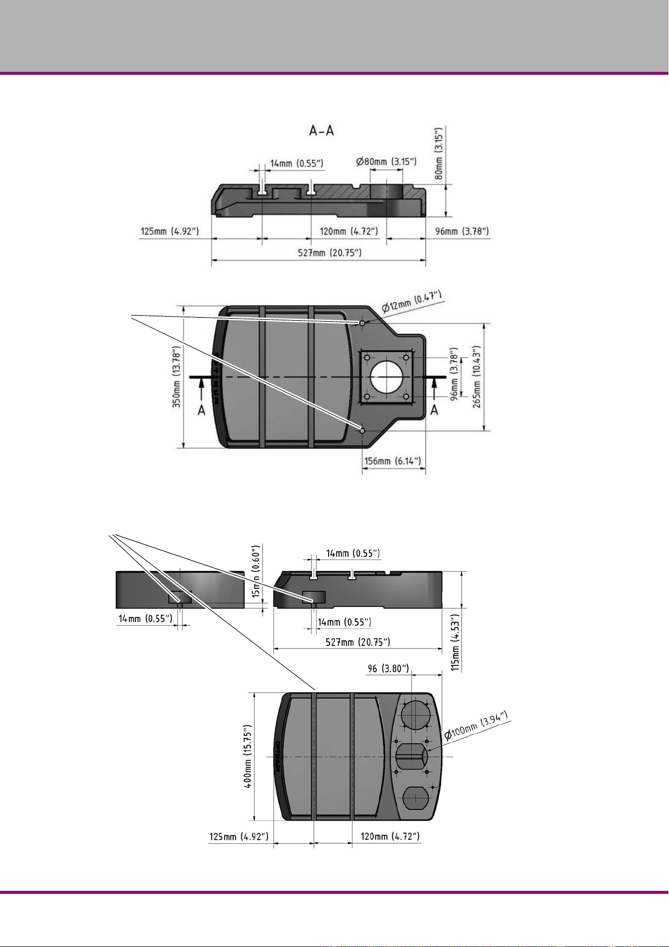
2.11 Dimensions B28HB
Fig.2-2: Dimensions B24HB

Page 21
B2
4H | B28H | B28HB | B28HV US
2.12 Dimensions B28H
Fig.2-3: Dimensions B28H

Page 2
2
B24H | B28H | B28HB | B28HVUS
2.13 Dimensions B28HV
Fig.2-4: Dimensions B28HV
Page 23
B2
4H | B28H | B28HB | B28HV US
3 Assembly
3.1 Scope of delivery
Please check immediately that nothing had been damaged during transportation and that all
components are complete. Compare the delivery volume to the attached packing list.
3.2 Transport
WARNING!
Machine parts which fall off forklift trucks or other transport vehicles could cause very
serious or even fatal injuries. Follow the instructions and information on the box.
WARNING!
Use of unstable lifting and load suspension gear that breaks under load can cause very
serious injuries or even death.
Check that the lifting and load suspension gear has sufficient load capacity and is in
perfect condition. Observe the rules for preventing accidents issued by your association
for the prevention of occupational accidents and safety in the workplace or other
inspection authorities.
Hold the loads properly. Never walk under suspended loads!
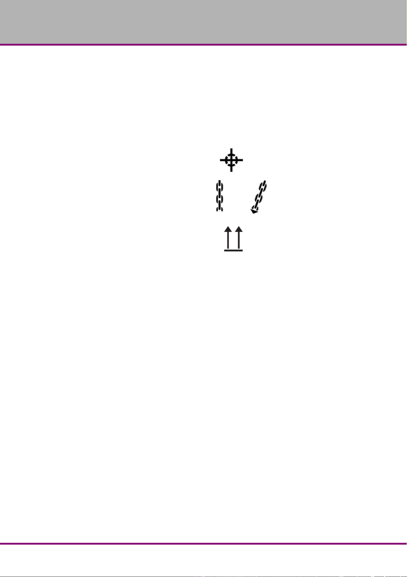
Center of gravity
Attachment positions (marking the positions for
the attachment position gear)
Prescribed transport position (marking the top
side)
Means of transportation to be used
Weights
Page 24
B24H | B28H | B28HB | B28HVUS
3.3 Storage
ATTENTION!
Improper storage may cause important parts to be damaged or destroyed.
Store packed or unpacked parts only under the following ambient conditions.
Please follow the instructions and indications on the transportation box:
Consult C.H.HANSON if the bench drill and upright drill and accessories have to be stored for
a period of over three months or under different external conditions than those given here
"Information“ on page
5.
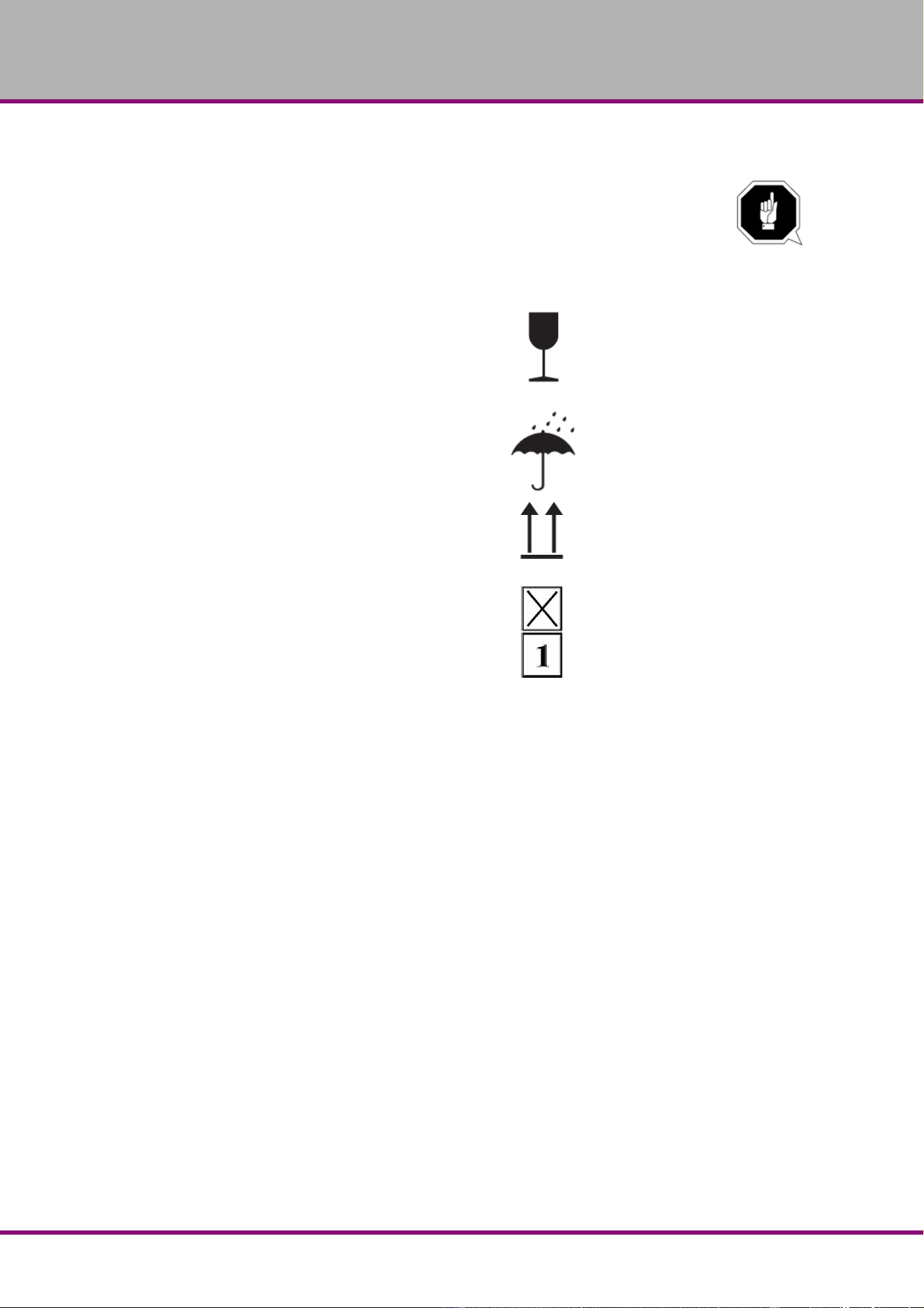
Fragile goods (goods require careful handling)
Protect against humidity and humid environments
"Environmental conditions“ on page 17.
Prescribed position of the packaging box (marking the
top side – arrows pointing upward)
Maximum stacking height
Example: non-stackable – do not pile any further
packaging boxes on top of the first packaging box

Page 25
B2
4H | B28H | B28HB | B28HV US
3.4 Installation and assembly
3.4.1 Site requirements
Organize the working space around the bench drill and upright drill according to the local safety
regulations.
INFORMATION
In order to provide for good functionality and high machining accuracy as well as long durability
of the machine the site should fulfill certain criteria.
Observe the following items:
The device must only be installed and operated in dry ventilated places.
Avoid places nearby machines generating chips or dust.
The site has to be vibration-free, i.e. at a distance from presses, planing machines, etc.
The substructure has to be appropriate for bench drill and upright drill. Also make sure that
the load bearing capacity and the evenness of the floor are appropriate.
The substructure has to be prepared in a way that possibly used coolant cannot penetrate
into the ground.
Protruding parts such as stops, handles, etc. need to be secured by measures provided by
the customer if necessary in order to avoid dangers for persons.
Provide sufficient space for assembly and operating staff as well as for material transport.
Also allow for accessibility for setting and maintenance works.
Make sure that the main power for the drilling machine is freely accessible.
Provide for sufficient illumination (minimum value: 47 Lumens/ft², measured at the tool tip).
In case of little intensity of illumination provide for additional illumination i.e. by a separate
workplace illuminator.
INFORMATION
The main power of the bench drill and upright drill has to be freely accessible.

Page 26
B24H | B28H | B28HB | B28HVUS
3.4.2 Assembly
WARNING!
Danger of crushing when grouping, assembling and mounting the machine components.
Assembly of base and column
INFORMATION
For the mounting of bench drill and upright drill you need a wrench and the hexagon screws
which are included in the delivery volume.
Put the base on the floor
and fix the column to the
stand. Use the hexagon
screws to
fix it.
Fig.3-1: Assembly column
column
B24H
base
B24H
hexagon screws
B24H
column B28H (B)
base B28H (B)
hexagon screws
B28H (B)
column B28HV
hexagon screws
B28HV
base B28HV

Page 27
B24H | B28H | B28HB | B28HV US
3.4.3 Assembly of the drilling machine table B24H (B28H B)
Insert the toothed rack in the drilling table.
Adjust the toothed rack within the drilling
machine table in a way that the teeth of the
toothed rack cam into the spiral wheel of the
support for the drilling machine table.
Insert the drilling table with the toothed rack
on the column.
Fig.3-2: Assembly drilling table B24H (Vario)
3.4.4 Assembly of the drilling machine table B28H (Vario)
Insert the toothed rack
in the drilling table.
Adjust the toothed rack
within the drilling
machine table in a way
that the teeth of the
toothed rack cam into
the spiral wheel of the
support for the drilling
machine table.
Insert the drilling with
the toothed rack on the
column.
Fig.3-3: Assembly drilling table B28H (Vario)
drilling table
toothed rack
column
drilling table
toothed rack
column

Page 2
8
B24H | B28H | B28HB | B28HVUS
Mount cooling equip-
ment.
Mount all cooling
agent hoses and fas-
ten you these with the
hose clamps.
Fig.3-4: Assembly drilling table B28H (Vario)
INFORMATION
The longer side of the
toothed rack without toothing
must be upside.
Insert the guide ring on to
the column and the
toothed rack.
Fix the guide ring and the
locking screw.
Make sure that you can still
easily turn the drilling table
round the column.
Fig.3-5: Assembly guide ring B28H (Vario)
drilling table
cooling equipment
column
cooling agent hoses
guide ring
locking screw
guide ring

Page 29
B2
4H | B28H | B28HB | B28HV US
Mount the crank handle to
the height adjustment arm
of the drilling table.
Tighten the crank handle
securly.
Fig.3-6: Mounting of crank handle
Mounting the boring head
Put the distance plate
on the column.
Fix the distance plate
with the cap screws on
the column.
Put the boring head on
the distance plate and
turn it until it aligns
with the base.
Fix the boring head
with the cap screws on
the distance plate.
Fig.3-7: Assembly boring head
3.5 Installation
Check the horizontal orientation of the base of the bench drill and upright drill with a spirit
level.
Check that the foundation has sufficient floor-load capacity and rigidityt.
Position the bench drill and upright drill on the intended foundation.
Attach the bench drill and upright drill using the provided recesses in the machine base.
WARNING!
The quality of the foundation and the mounting method of the machine base to the
foundation has to assimilate the loads of the machine. The foundation needs to be even.
Please check the horizontal alignment of the foundation of the machine with a spirit
level.
hexagon screw
crank handle
cap screws
distance plate
cap screws

Page 3
0
B24H | B28H | B28HB | B28HVUS
3.5.1 Mounting
In order to provide for the necessary stability of the drilling machine it is necessary to firmly bolt
the base of the machine to the foundation. We recommend you to use compound anchor cart-
ridges or heavy duty anchors.
Mount the drilling machine to the
foundation using the provided
through-holes on the base.
The through-holes are marked
with arrows on the machine base.
Fig.3-8: Labeling of the anchorage point on drilling
machine B24H, B28H (B)
Fig.3-9: Labeling of the anchorage point on drilling
machine B28H (Vario)
Fig.3-10: Bottom attachment
ATTENTION!
Tighten the anchor bolt nuts on the bench drill and upright drill only until it is firmly
secured and can neither move during operation nor be turned over.
If the anchor bolt nuts are too tight and the foundation is uneven, the base of the bench drill and
upright drill may break.
Through-hole
Arrow sign
Arrow sign
Through-hole
Page 31
B2
4H | B28H | B28HB | B28HV US
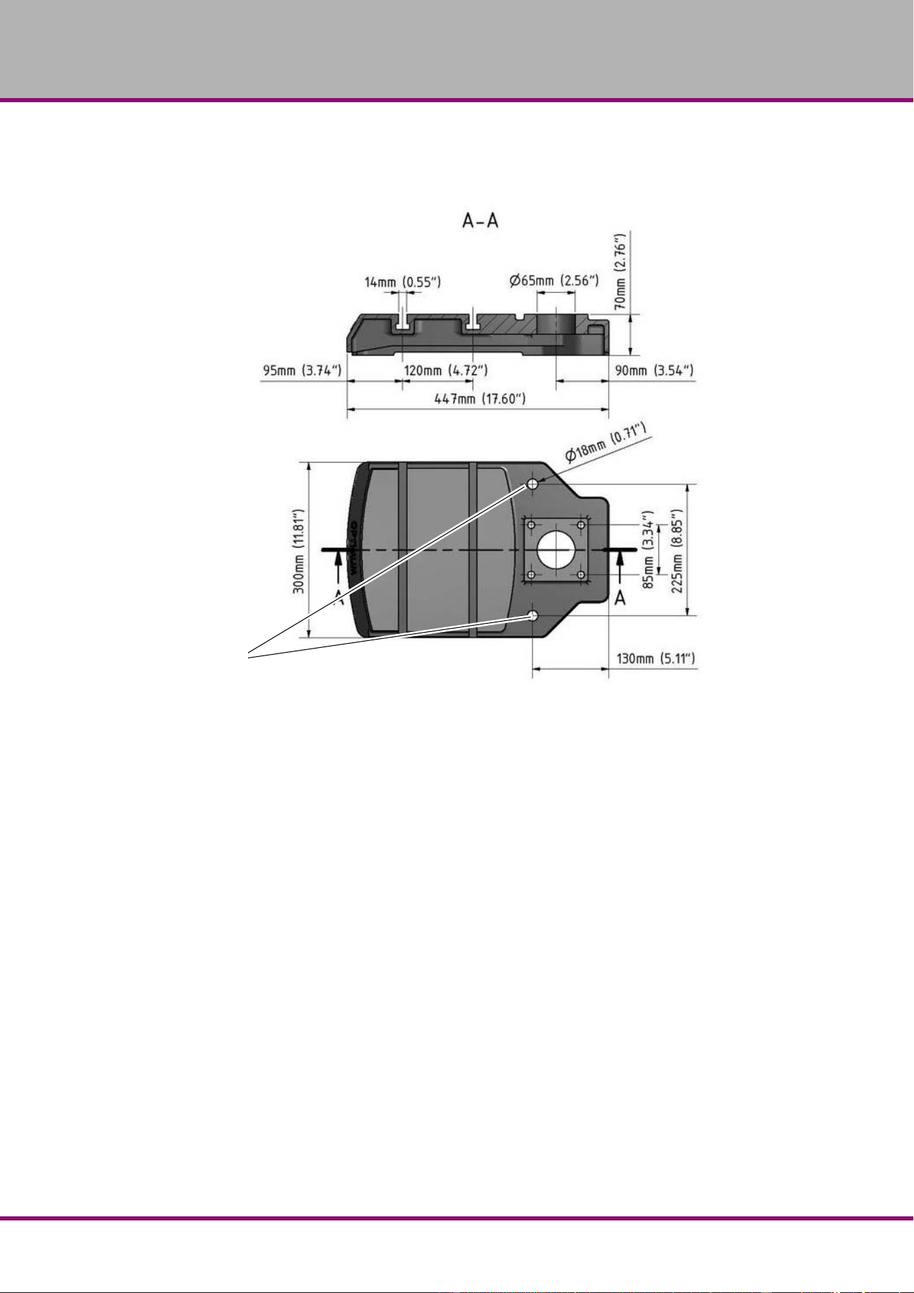
3.5.2 Installation drawings
B24H
Fig.3-11: B24H
Fixing (2)
Page 3
2
B24H | B28H | B28HB | B28HVUS
B28H (B)
Fig.3-12: B28H
B28H (Vario)
Fig.3-13: B28H (Vario)
Fixing (2)
Fixing (3)

Page 33
B24H | B28H | B28HB | B28HV US
3.6 First use
WARNING!
Risk by using improper workpiece clamping materials or by operating the machine with
inadmissible speed.
Only use the clamping materials (e.g. drill chuck) which had been delivered together with
the machine or as optional equipment offered by company.
Use the working clamping materials only in the provided admissible speed range.
Workpiece clamping materials must only be modified according to the recommendations
of company or of the clamping material manufacturer.
WARNING!
Staff and equipment may be endanged if the bench drill and upright drill is first used by
unexpert staff.
We do not take responsibility for damage caused by incorrect commissioning.
"Qualification of employees“ on page 9
Power supply
Connect the electrical feeds.
Check the fuse protection (fuse) of your electrical supply according to the technical specifi-
cations for the total connected load of the bench drill and upright drill.
ATTENTION!
For 230V machines
: Imperatively make sure that all 3 phases (L1, L2, L3) are connected
correctly.
Most of the defects on motors are resulting from wrong connections. For instance, if a
motor phase is not correctly clamped or connected to the neutral conductor (N)
.
This may cause:
That the motor is becoming hot very rapidly
Increased motor noises.
The motor has no power.
ATTENTION!
Make sure that the direction of rotation of the drive motor is correct. If the rotational
direction switch is switched to the position to perform clockwise rotations (R) the drill
spindle needs to rotate clockwise. If necessary, exchange two phase connections.
If your connector plug is equipped with a phase inverter, this is done by turning it by
180°.
If the machine is wrongly connected the warrantee will become null and void.
Page 34
B24H | B28H | B28HB | B28HVUS
4 Operation
4.1 Safety
Use the machine only under the following conditions:
The machine is in proper working order.
The machine is used as prescribed.
The instruction manual has been followed.
All safety devices are installed and activated.
All malfunctions should be eliminated immediately. Stop the machine immediately at an event
of any malfunction in operation and make sure it cannot be started up accidentally or without
authorization.
Notify the person responsible immediately of any modification.
"Safety during operation“ on page 14
4.2 Control and indicating elements
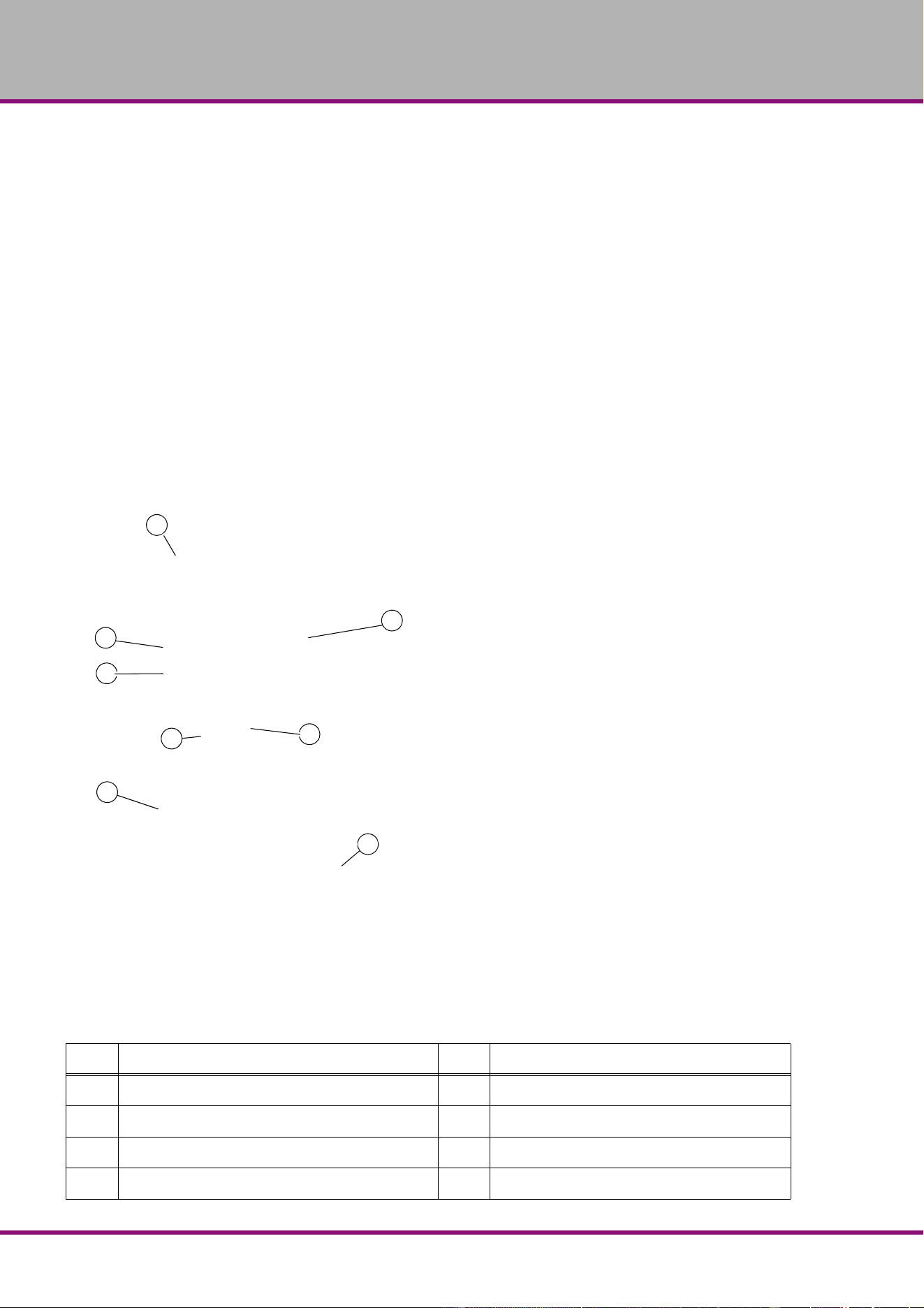
4.2.1 Drilling machine B24H | B28 HB
Img.4-1: B24H | B28HB
Pos. Description Pos. Description
1
Belt drive with housing
2
Lever for spindle sleeve feed
3
Emergency stop
4
On/Off Control
5
Drill chuck
6
Drilling table
7
Table height adjustment
8
Lever for belt tension
1
2
3
4
5
8
6
7
Page 35
B2
4H | B28H | B28HB | B28HV US
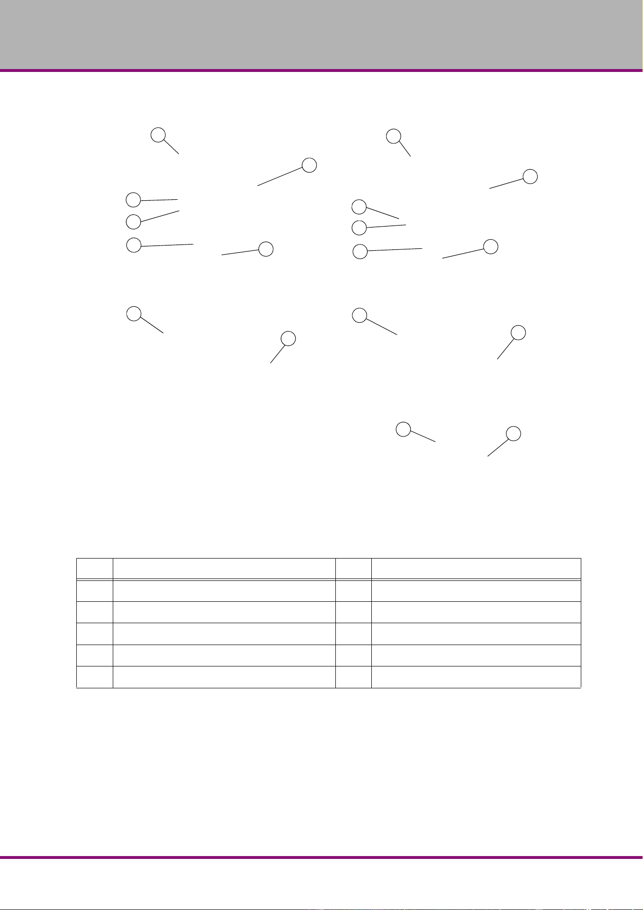
4.2.2 Drilling machine B28H | B28HV
Img.4-2: B28H | B28HV
Pos. Description Pos. Description
1
Belt drive with housing
2
Lever for spindle sleeve feed
3
Emergency stop
4
On/Off Control
5
Drill chuck
6
Drilling table
7
Table height adjustment
8
Lever for belt tension
10
Coolant agent equipment B28HV
11
chip filter B28HV
1
3
3
4
5
5
8
8
6
6
7
7
1
4
2
2
10
11

Page 3
6
B24H | B28H | B28HB | B28HVUS
4.2.3 Control panel B24H
Fig.4-3: Operating element on the control panel B24H
4.2.4 Control panel B28H (Vario), B28HB
Fig.4-4: Operating element on the control panel B28H | B28HB
Fig.4-5: Operating element on the control panel B28HV
Machine lamp ON/OFF
Selector switch operating
mode
left-hand / right-hand rotation
Push button „ON“
EMERGENCY-STOP but-
ton
Push button „OFF“
Machine lamp ON/OFF
Selector switch operating
mode
left-hand / right-hand rotation
Push button „ON“
EMERGENCY-STOP button
Push button „OFF“
Speed display
Selector switch operating mode
left-hand / right-hand rotation
EMERGENCY-STOP button
Machine lamp ON/OF
Coolant pump ON/OFF
Potentiometer
Push button „ON“
Push button „OFF“

Page 37
B24H | B28H | B28HB | B28HV US
Switch for the turning direction
Standard operation, selection right-handed or left-handed rotation.
Potentiometer
Speed setting "VARIO"
Push button ON
The push button „ON“
will start up the rotation of the drill spindle.
Push button OFF
The push button „OFF“
switches off the rotation of the drill spindle.
Coolant pump ON / OFF
Switches the coolant pump ON or OFF.
Machine lamp ON / OFF
Switches the coolant pump ON or
OFF.
Fig.4-6: Machine lamp B24H | B28H | B28HB | B28HV
Operating control lamp
The operating control lamp on the operating panel has to flash.
Main switch
Interrupts or connects the power supply.
Machine lamp
B24H/ B28H (B) (Vario)

Page 3
8
B24H | B28H | B28HB | B28HVUS
4.3 Turn the machine on B24H / B28H / B28HB
Turn the main switch on.
Select the turning direction.
Actuate the push button „ON“.
4.4 Turn the machine on B28HV
Turn the main switch on.
Select the turning direction.
Actuate the push button „ON“.
4.5 Turn the machine off B24H / B28H / B28HB
Actuate the push button „OFF“.
If the machine stands still for a longer period of time, switch off the main switch.
4.6 Turn the machine off´B28H Vario
Actuate the push button „OFF“.
If the machine stands still for a longer period of time, switch off the main switch.

Page 39
B2
4H | B28H | B28HB | B28HV US
4.7 Speed variation
WARNING!
Danger due to drill chuck or tools flying off at high speed. Make sure not to exceed the
maximum speed of the drill chuck when setting the spindle speed.
Switch off the main switch of the
machine.
Open the protective cover.
Loosen the clamping lever of
the V-belt tension.
Put the V-belt to the required
position.
Fig.4-7: Lever for the V-belt tension B24H
Tension the clamping lever.
Close the protective cover.
Fig.4-8: Lever for the V-belt tension B28H | B28HB | B28HV
V-belt
lever
V-belt tension
V-belt
lever
V-belt tension

Page 40
B24H
| B28H | B28HB | B28HVUS
4.7.1 Speed table B24H
Fig.4-9: Speed table B24H
4.7.2 Speed table B28H - B28HB
Fig.4-10: Speed table B28H | B28HB

Page 41
B24H
| B28H | B28HB | B28HV US
4.7.3 Speed table B28HV
Fig.4-11: Speed table B28HV
4.8 Drill depth stop
When drilling several
holes of the same depth,
you can use the drill depth
stop.
Loosen the locking
screw and turn the
graduated collar until
the required drilling
depth matches with
the indicator.
Re-tighten the locking
screw.
Fig.4-12: drill depth stop
Scale
Locking screw
drill depth stop

Page 4
2
B24H | B28H | B28HB | B28HVUS
4.9 Removing, mounting of drill chucks and drills
4.9.1 Keyless drill chuck
The drill chuck consists of two
parts (No. 1 and No. 2)
.
Hold the upper part (No. 1)
of the drill chuck. With the
lower part (No. 2) of the drill
chuck one can firm and/or
loose-turn the cheeks of the
drill chuck.
Turn the tool (drill) firmly.
Fig.4-13: drill chuck
ATTENTION!
Make sure that the chucked tool is positioned firmly and correctly.
4.9.2 Removing the drill chuck
The drill chuck and the morse taper are released from the drill spindle by a drill drift.
WARNING!
Remove the drill chuck only when the bench drill and upright drill is disconnected from
the electrical power supply.
Switch off the bench
drill and upright drill with
the main switch or dis-
connect the power plug.
Turn the drill spindle
downwards.
Turn the drill spindle in
a way that the openings
on the drill quill and on
the drill spindle are
superimposed.
Loosen the morse taper
of the drill chuck by
means of a drill drift.
Fig.4-14: Disassembly B24H
upper part (No.1)
Keyless drill chuck
lower part (No. 2)
Keyless drill chuck
tool (drill)
drill drift
drill quill
upper part quick
action drill chuck
lower part quick
action drill chuck

Operation
Version 2.1.8 dated 2015-03-30
4.9.3 Removing the tool or drill chuck with the integrated drill drift on the B28H (B, Vario)
CAUTION!
Hold the tool or the drill chuck.
With the below described procedure the
taper mandrel is being loosened from the
drill spindle. The tool and/or the drill chuck
will fall down.
CAUTION!
Do not try to expel the tool when it is in the
intermediate position. This might cause
damages of the integrated drill drift or of
the feed handle.
Lower the spindle until the two circum-
scribed lines on the quill are visible.
Push the locking pin inside the quill
fully inside. Be sure that the pin is fully
engaged. inside the quill.
Raise the spindle upward while holding
the chuck.
The chuck arbor will be pushed out of the
spindle.
Pull out the locking pin fully out of the
quill.
Fig.4-15: Disassembly B28HB | B28H | B28HV
4.9.4 Mounting the drill chuck B24H and B28H (B, Vario)
The keyless drill chuck is
secured through a form-fit
union (driver) against twist-
ing in the drill spindle.
A friction-locking union
holds and centers the key-
less drill chuck with the
taper mandrel in the drill
spindle.
Fig.4-16: taper mandrel
Check and if necessary, clean the conical seat in the drill spindle and at the taper mandrel
of the tool or the keyless drill chuck.
Press the taper mandrel into the drill spindle.
1
2
2
1
1
drill spindle
driver
taper mandrel

Page 4
4
B24H | B28H | B28HB | B28HVUS
4.10 Cooling
The friction generated during rotation can cause the edge of the tool to become very hot.
The tool should be cooled during the drilling process. Cooling the tool with a suitable cooling
lubricant ensures better working results and a longer edge life of the tools.
This is best realised by a separate cooling equipment. If there is no cooling equipment included
in the delivery volume, you can cool by means of a spray gun or a washing bottle.
Fig.4-17: Charging hole B28HV
Fig.4-18: Coolant shut-off valve B28HV
Adjust the flow using the shut-off valve.
ATTENTION!
Failure of the pump in the event of a dry run.
The pump is lubricated by the cooling agent. Do not start up the pump without cooling
agent.
CAUTION!
Danger of injury due to brushes getting caught or pulled in.
Use a spray gun or a washing bottle for cooling.
INFORMATION
Use a water-soluble and non-polluant drilling emulsion which can be obtained from authorized
distributors.
Make sure that the cooling agent is being collected.
Respect the environment when disposing any lubricants and cooling agents.
Follow the manufacturer’s disposal instructions.
Coolant charging hole
Coolant shut-off valve

Page 45
B2
4H | B28H | B28HB | B28HV US
4.11 Before starting the working process
Before you start working, select the required speed. It is depending on the drilling diameter and
on the material used.
"Speed table B24H“ on page 40, "Speed table B28H - B28HB“ on page 40
WARNING!
For drilling jobs, it is necessary to clamp the workpiece firmly to prevent the bit catching
on the pieces. Example of suitable clamping devices include a machine vice or clamping
jaws.
Put a wooden or plastic board beneath the workpiece to avoid drilling through to the work table,
vice, etc.
Use the drill depth stop when you want to have several bore holes with the same depth.
When working with wood, make sure to use an adequate dust extraction unit, as sawdust can
constitute a health hazard. Also use a suitable protective mask for any work that generates
dust.
4.12 During the working process
The spindle feed is being performed by the star grip. Make sure that the feed is being at a regu-
lar pace and not to fast.
The reset of the spindle is being performed by a track recoil spring.
WARNING!
Danger of clothing / or long hair getting caught.
Make sure to wear a well-fitting work suit during drilling work.
Do not use gloves.
If necessary, wear a hairnet.
CAUTION!
Danger of bumps by the levers on the star grip.
Do not release the star grip when repositioning the drill spindle sleeve.
CAUTION!
Danger of crushing! Do not place your hand between the drill head and the spindle
sleeve.
The smaller the bit, the more likely it is to break.
In the case of deep drilling, remove the bit from time to time to remove drilling chips from the
bore hole. A few drops of oil will reduce friction and prolong the service life of the bit.

Page 4
6
B24H | B28H | B28HB | B28HVUS
5 Determining the cutting speed and the speed
5.1 Table cutting speeds / infeed
5.2 Speed table
Material table
Material to be processed
Recommended
cutting speed
Vc in m/min
Recommended infeed f
in mm/revolution
Drill bit diameter d in mm
2...3 >3...6 >6...12 >12...25 >25...50
Unalloyed construction steels
< 700 N/mm²
30 - 35 0.05 0.10 0.15 0.25 0.35
Alloyed construction steels
> 700 N/mm²
20 - 25 0.04 0.08 0.10 0.15 0.20
Alloyed steels
< 1000 N/mm²
20 - 25 0.04 0.08 0.10 0.15 0.20
Steels, low stability
< 800 N/mm²
40 0.05 0.10 0.15 0.25 0.35
Steel, high stability
> 800 N/mm²
20 0.04 0.08 0.10 0.15 0.20
non-rust steels
> 800 N/mm²
12 0.03 0.06 0.08 0.12 0.18
Cast iron
< 250 N/mm²
15 - 25 0.10 0.20 0.30 0.40 0.60
Cast iron
> 250 N/mm²
10 - 20 0.05 0.15 0.25 0.35 0.55
CuZn alloy
brittle
60 - 100 0.10 0.15 0.30 0.40 0.60
CuZn alloy
ductile
35 - 60 0.05 0.10 0.25 0.35 0.55
Aluminum alloy
up to 11% Si
30 - 50 0.10 0.20 0.30 0.40 0.60
Thermoplastics 20 - 40 0.05 0.10 0.20 0.30 0.40
Thermosetting materials with
organic filling
15 - 35 0.05 0.10 0.20 0.30 0.40
Thermosetting materials with
anorganic filling
15 - 25 0.05 0.10 0.20 0.30 0.40
Vc
in m/min
4 6 8 10 12 15 18 20 25 30 35 40 50 60 80 100
Drill bit Ø
in mm
Speed n in rpm
1.0 1274 1911 2548 3185 3822 4777 5732 6369 7962 9554 11146 12739 15924 19108 25478 31847
1.5 849 1274 1699 2123 2548 3185 3822 4246 5308 6369 7431 8493 10616 12739 16985 21231
2.0 637 955 1274 1592 1911 2389 2866 3185 3981 4777 5573 6369 7962 9554 12739 15924
2.5 510 764 1019 1274 1529 1911 2293 2548 3185 3822 4459 5096 6369 7643 10191 12739
3.0 425 637 849 1062 1274 1592 1911 2123 2654 3185 3715 4246 5308 6369 8493 10616
3.5 364 546 728 910 1092 1365 1638 1820 2275 2730 3185 3640 4550 5460 7279 9099
4.0 318 478 637 796 955 1194 1433 1592 1990 2389 2787 3185 3981 4777 6369 7962
Vc
in m/min
4 6 8 10 12 15 18 20 25 30 35 40 50 60 80 100

Page 47
B2
4H | B28H | B28HB | B28HV US
Drill bit Ø
in mm
Speed n in rpm
4.5 283 425 566 708 849 1062 1274 1415 1769 2123 2477 2831 3539 4246 5662 7077
5.0 255 382 510 637 764 955 1146 1274 1592 1911 2229 2548 3185 3822 5096 6369
5.5 232 347 463 579 695 869 1042 1158 1448 1737 2027 2316 2895 3474 4632 5790
6.0 212 318 425 531 637 796 955 1062 1327 1592 1858 2123 2654 3185 4246 5308
6.5 196 294 392 490 588 735 882 980 1225 1470 1715 1960 2450 2940 3920 4900
7.0 182 273 364 455 546 682 819 910 1137 1365 1592 1820 2275 2730 3640 4550
7.5 170 255 340 425 510 637 764 849 1062 1274 1486 1699 2123 2548 3397 4246
8.0 159 239 318 398 478 597 717 796 995 1194 1393 1592 1990 2389 3185 3981
8.5 150 225 300 375 450 562 674 749 937 1124 1311 1499 1873 2248 2997 3747
9.0 142 212 283 354 425 531 637 708 885 1062 1238 1415 1769 2123 2831 3539
9.5 134 201 268 335 402 503 603 670 838 1006 1173 1341 1676 2011 2682 3352
10.0 127 191 255 318 382 478 573 637 796 955 1115 1274 1592 1911 2548 3185
11.0 116 174 232 290 347 434 521 579 724 869 1013 1158 1448 1737 2316 2895
12.0 106 159 212 265 318 398 478 531 663 796 929 1062 1327 1592 2123 2654
13.0 98 147 196 245 294 367 441 490 612 735 857 980 1225 1470 1960 2450
14.0 91 136 182 227 273 341 409 455 569 682 796 910 1137 1365 1820 2275
15.0 85 127 170 212 255 318 382 425 531 637 743 849 1062 1274 1699 2123
16.0 80 119 159 199 239 299 358 398 498 597 697 796 995 1194 1592 1990
17.0 75 112 150 187 225 281 337 375 468 562 656 749 937 1124 1499 1873
18.0 71 106 142 177 212 265 318 354 442 531 619 708 885 1062 1415 1769
19.0 67 101 134 168 201 251 302 335 419 503 587 670 838 1006 1341 1676
20.0 64 96 127 159 191 239 287 318 398 478 557 637 796 955 1274 1592
21.0 61 91 121 152 182 227 273 303 379 455 531 607 758 910 1213 1517
22.0 58 87 116 145 174 217 261 290 362 434 507 579 724 869 1158 1448
23.0 55 83 111 138 166 208 249 277 346 415 485 554 692 831 1108 1385
24.0 53 80 106 133 159 199 239 265 332 398 464 531 663 796 1062 1327
25.0 51 76 102 127 153 191 229 255 318 382 446 510 637 764 1019 1274
26.0 49 73 98 122 147 184 220 245 306 367 429 490 612 735 980 1225
27.0 47 71 94 118 142 177 212 236 295 354 413 472 590 708 944 1180
28.0 45 68 91 114 136 171 205 227 284 341 398 455 569 682 910 1137
29.0 44 66 88 110 132 165 198 220 275 329 384 439 549 659 879 1098
30.0 42 64 85 106 127 159 191 212 265 318 372 425 531 637 849 1062
31.0 41 62 82 103 123 154 185 205 257 308 360 411 514 616 822 1027
32.0 40 60 80 100 119 149 179 199 249 299 348 398 498 597 796 995
33.0 39 58 77 97 116 145 174 193 241 290 338 386 483 579 772 965
34.0 37 56 75 94 112 141 169 187 234 281 328 375 468 562 749 937
35.0 36 55 73 91 109 136 164 182 227 273 318 364 455 546 728 910
36.0 35 53 71 88 106 133 159 177 221 265 310 354 442 531 708 885
37.0 34 52 69 86 103 129 155 172 215 258 301 344 430 516 689 861
38.0 34 50 67 84 101 126 151 168 210 251 293 335 419 503 670 838
Vc
in m/min
4 6 8 10 12 15 18 20 25 30 35 40 50 60 80 100

Page 4
8
B24H | B28H | B28HB | B28HVUS
5.3 Examples to calculatory determine the required speed for your drilling machine
The necessary speed is depending on the diameter of the drill bit, on the material which is
being machined as well as on the cutting material of the drill bit.
Material which needs to be drilled: St37
Cutting material (drill bit): HSS spiral bit
Set point of the cutting speed [
v
c
] according to the table: 40 meters per minute
Diameter [d] of your drill bit: 30 mm = 0.03 m [meters]
Selected infeed [f] according to the table: about 0.35 mm/rev
Speed
Set a speed on your drilling machine which is less than the determined speed.
INFORMATION
In order to facilitate the production of larger drill holes they need to be pre-drilled. This way, you
reduce the cutting forces and improve the guiding of the drill bit.
The pre-drilling diameter is depending on the length of the
chisel edge. The chisel edge does not cut, but it squeezes
the material. The chisel edge is positioned at an angle of
55° to the major cutting edge.
As a general rule of thumb it applies: The pre-drilling
diameter is depending on the length of the chisel edge.
Recommended working steps for a drilling diameter of 30 mm
Example:
1st working step: Pre-drilling with Ø 5 mm (0.2").
2nd working step: Pre-drilling with Ø 15 mm (0.6").
3rd working step: Drilling with Ø 30 mm (1.2").
Drill bit Ø
in mm
Speed n in rpm
39.0 33 49 65 82 98 122 147 163 204 245 286 327 408 490 653 817
40.0 32 48 64 80 96 119 143 159 199 239 279 318 398 478 637 796
41.0 31 47 62 78 93 117 140 155 194 233 272 311 388 466 621 777
42.0 30 45 61 76 91 114 136 152 190 227 265 303 379 455 607 758
43.0 30 44 59 74 89 111 133 148 185 222 259 296 370 444 593 741
44.0 29 43 58 72 87 109 130 145 181 217 253 290 362 434 579 724
45.0 28 42 57 71 85 106 127 142 177 212 248 283 354 425 566 708
46.0 28 42 55 69 83 104 125 138 173 208 242 277 346 415 554 692
47.0 27 41 54 68 81 102 122 136 169 203 237 271 339 407 542 678
48.0 27 40 53 66 80 100 119 133 166 199 232 265 332 398 531 663
49.0 26 39 52 65 78 97 117 130 162 195 227 260 325 390 520 650
50.0 25 38 51 64 76 96 115 127 159 191 223 255 318 382 510 637
n
c
d
------------
40m
min 3 14 0 03m
---------------------------------------------------
425 rpm===
Chisel edge length 10% of the
drill bit - Ø
Page 49
B24H | B28H | B28HB | B28HV US
6 Maintenance
In this chapter you will find important information about
inspection,
maintenance,
repair.
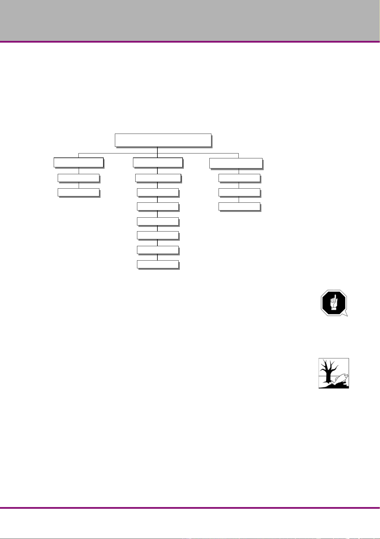
The diagram below shows which of these headings each task falls under.
Fig.6-1: Maintenance – Definition according to DIN 31051
ATTENTION!
Properly performed regular maintenance is an essential prerequisite for
safe operation,
faulty-free operation,
long service life of the machine and
the quality of the products you manufacture.
Installation and equipment from other manufacturers must be in company condition.
ENVIRONMENTAL PROTECTION
During work on the drilling head, make sure that
collector vessels are used, with sufficient capacity for the amount of liquid to be col-
lected.
liquid and oils are not split on the ground.
Clean up any split liquids or oils immediately using proper oil-absorption methods and dispose
of them in accordance with current legal requirements on the environment.
Cleaning up spills
Do not re-introduce liquids spilt outside the system during repair or as result of leakage from the
reserve tank: collect them in a collecting vessel to be disposed of.
Disposal
Never dump oil or other pollutant substances in water inlets, rivers or channels.
Used oils must be delivered to a collection centre. Consult your superior if you do not know
where the collection centre is.
Maintenance
Inspection Maintenance
Repair
Measuring Rough cleaning Mending
Testing Fine cleaning Replacing
Conserving
Lubricating
Completing
Replacing
Readjusting
Adjusting

Page 5
0
B24H | B28H | B28HB | B28HVUS
6.1 Safety
WARNING!
The consequences of incorrect maintenance and repair work may include:
very serious injury to employees working on the machine,
damage to the machine.
Only qualified staff should carry out maintenance and repair work on the machine.
6.1.1 Preparation
WARNING!
Only carry out work on the machine if it has been disconnected from the main power
supply.
Position a warning sign.
6.1.2 Restarting
Before restarting run a safety check.
"Safety check“ on page 11
WARNING!
Before activating the machine, double check that this will not
endanger other people,
damage the machine.
6.2 Inspection and maintenance
This type and extent of wear depends to a large extent on individual usage and service condi-
tions.
For this reason, all the intervals are only valid for the authorized conditions.
Interval Where? What? How?
start of shift
after each
maintenance or
repair operation
bench drill and upright drill
Examination for outside damages.
"Safety check“ on page 11

Page 51
B2
4H | B28H | B28HB | B28HV US
every month
column and rack
lubricate
• Lubricate the column with commercial oil, machine oil, motor oil.
• Lubricate the rack regularly with commercial grease (e.g. friction
bearing grease).
Img.6-2: B24H | B28HB | B28H | B28HV
every six
months
V-belts on the drilling head
visual inspection
• Check whether the V-belts have become porous and worn.
Img.6-3: V-belt housing
Interval Where? What? How?
column
toothed rack
V-belt B24H
V-belt B28H (Vario)

Page 5
2
B24H | B28H | B28HB | B28HVUS
every month
Oiler
Lubricate
Lubricate all oilers with machine oil, do not use a grease gun
or similar greasing equipment. Use the oil bottle in included
with the machine.
"Operating material“ on page 17
Fig.6-4: Oiler B24H | B28HB | B28H | B28HV
every six
months
electric
check
Check the electrical equipment / parts of the drilling machine.
"Qualification of employees“ on page 9
The cooling pump is almost entirely maintenance-free.
Replace the cooling agent regularly, depending on usage.
When using coolants which leave residues, the coolant pump
must be removed and rinsed possibly.
Suck the old cooling agent off with a suitable industrial suc-
tion cup over the charging hole.
Fill in new coolant over the chip tray. The maximum capacity
of the coolant is about 3.7 quarts.
Fig.6-5: Coolant tank B28HV
Interval Where? What? How?
Oiler
Coolant charging
hole

Page 53
B24H | B28H | B28HB | B28HV US
INFORMATION!
The spindle bearing arrangement is prelubricated. It is not required to relubricate it.
6.3 Repair
Repairs must be carried out only by qualified technical staff; and must follow the instructions and
guidelines given in this manual. Should technical assistance be required, contact C.H.HANSON
at 1-630-785-6437.
Company and C.H.HANSON are not liable for, nor do they guarantee against, damage or
operating malfunctions resulting from alteration, abuse, lack of main-tenance or
this product’s use for other than its intended purpose. Failure to read and follow this
operating manual is not covered.
For repairs only use
Proper and suitable tools,
Parts purchased from company, or its authorized agent.
as required
spindle return spring
adjust stretch return spring
CAUTION!
Parts will throw out at high pressure. When disas-
sembling, make sure that only skilled staff will
maintain and repair the machine.
Img.6-6: Spindle return spring
Img.6-7: Exploded view of the spring barrel
Interval Where? What? How?
spring barrel
circlip
flat spiral spring
spring barrel
circlip

Page 5
4
B24H | B28H | B28HB | B28HVUS
7 Spare parts - B24H | B28H | B28HB | B28HV
7.1 B24H
7.1.1 Drilling head B24H
Fig.7-1: Drilling head B24H

Page 55
B2
4H | B28H | B28HB | B28HV US
7.1.2 Column and drilling table B24H
Fig.7-2: Column and drilling table B24H

Page 5
6
B24H | B28H | B28HB | B28HVUS
7.1.3 Pulleys B24H
Fig.7-3: Pulleys B24H
7.1.4 Parts list B24H
B24H
Pos.
Description Qty. Size Item no.
1 Base 1 030202411
2 Column 1 030202412
3 Toothed rack 1 030202413
4 Toothed wheel 1 030202414
5 Drive screw 1 030202415
5-1 Spacer 1 0302024151
6 Drill chuck 1 B16 030202416
6-1 Drill chuck (year on construction since 12/2009) 1 3050626
7 Spindle 1 030202417
8 V-belt 1 030202418
9 Spindle sleeve 1 030202419
10 Socket head screw 4 M10x60 0302024110
10-1 Washer 4 GB/T93-1987-10 03020241101
10-2 Washer 4 GB/T97.1-1985-10 03020241102

Page 57
B2
4H | B28H | B28HB | B28HV US
11 Drilling machine table 1 0302024111
11-1 Threaded pin 1 M6x6 03020241111
12 Ball bearing 1 6205 0302024112
13 Spacer 2 0302024113
14 Screw 1 JB-T7270.4-1994-2 0302024114
15 Case 1 JB-T7270.4-1994-1 0302024115
15-1 Handle complete 1 JB-T7270.4-1994 03020241151
16 Crank 1 0302024116
17 Spindle feed grip 1 0302024117
18 Socket head screw 1 M5x25 0302024118
19 Plate 1 0302024119
20 Bushing scale 1 0302024120
21 Scale ring 1 0302024121y
22 Scale 1 0302024122
23 Clamping screw 1 0302024123
23-1 Label „spans“ „release“ 1 03020241231
23-2 Socket head screw 2 M3x10 03020241232
24 Bushing quick action grip 1 0302024124
24-1 Quick action grip 1 03020241241
25 Bolt span 1 0302024125
25-1 Hexagonal nut 1 M10 03020241251
26 Hexagon bolt 4 M8x25 0302024126
26-1 Washer 4 GB/T93-1987-8 03020241261
26-2 Washer 4 GB/T97.1-1985-8 03020241262
27 Motor 1 0302024127
28 Feather key 1 6x6x20 0302024128
29 Socket head screw 3 M5x10 0302024129
29-1 Washer 3 5 03020241291
30 Belt housing bottom part 1 0302024130
30-1 Articulation 2 03020241301
30-2 Washer 12 4 03020241302
30-3 Hexagonal nut 12 M4 03020241303
31 Pulley 1 M6x8 0302024131
31-1 Threaded pin 1 03020241311
32 Belt housing upper part 1 0302024132
34 Spindle 1 0302024134
35 Plate closer 1 0302024135
36 Socket head screw 4 M6x12 0302024136
36-1 Washer 4 03020241361
37 Spindle nut 1 0302024137
37-1 Ball bearing 1 6003-2Z 03020241371
37-2 Socket head screw 2 M4x8 03020241372
38 Pulley 1 0302024138
39 Socket head screw 7 M6x15 0302024139
40 Holder plate 1 0302024140
41 motor plate 1 0302024141
42 Drilling head 1 0302024142
42-1 Washer 4 03020241421
42-2 Plat
e 1 03020241422
42-3 Socket head screw 4 M6x12 03020241423
42-4 Bushing 1 030202414234
43 Spacer ring 1 0302024143
44 Ball bearing 2 6005 0302024144
45 Circlip 2 DIN472 47x1.6 0302024145
46 Socket head screw 3 M4x10 0302024146
47 Covering plate 1 0302024147
48 Socket head screw 2 M6x30 0302024148
48-1 Socket head screw 1 03020241481
49 Fixing drill chuck proetection 1 0302024149
50 Knurled screw 1 M6x30 0302024150
51 Arm drill chuck protection 1 20x20 0302024151
53 View sealing pane drill chuck protection 1 0302024153
53-1 Switch drill chuck 1 230V 0,5A 03020241531
55 circlip 1 DIN471-12x1 0302024155
56 Box spiral spring 1 0302024156
57 Spiral spring 1 0302024157
58 Bushing toothed shaft 1 0302024158
58-1 Split pin 2 3x12 03020241581
58-2 Spanner spiral spring 1 03020241582
B24H
Pos.
Description Qty. Size Item no.

Page 5
8
B24H | B28H | B28HB | B28HVUS
60 Switch plate 1 0302024160
61 Switch On / OFF (old version 1.0) 1 0302024161
62 Socket head screw 4 M4x8 0302024162
63 Machine lightning switch 1 250V 6A 0302024163
64 Socket head screw 12 M4x10 0302024164
65 Socket head screw 2 M6x20 0302024165
66 O-ring 1 0302024166
67 sliding block 1 0302024167
68 Setscrew 1 M8x15 0302024168
69 Cover illumination 1 0302024169
69-1 Lamp (diode) 1 12V 03020241691
70 Shank pinion 1 0302024170
70-2 Mechanicel indicator scale 1 03020241702
70-3 Ring 1 03020241703
70-4 Socket head screw 2 M6x16 03020241704
70-5 Spring pin 1 03020241705
71 Plate 1 M8x30 0302024171
71-1 Socket head screw 4 03020241711
72 Socket head screw 4 M10x25 0302024172
73 Shaft 1 0302024173
74 Oiler 1 0302024174
75 Clamping lever 1 0302024175
76 Socket head screw 1 M6x20 0302024176
77 Socket head screw 1 M12x60 0302024177
78 Clamping screw 1 M12x60 0302024178
78-1 Washer 1 12 03020241781
79 Knurled screw 1 M8x20 0302024179
80 Sliding block 1 0302024180
81 Straight pin 1 6x40 0302024181
82 Pressure Oil Cup 2 0302024182
83 Spacer 1 0302024183
83-1 Threaded pin 1 M6x6 03020241831
84 Key 1 8x8x18 0302024184
85 Bush button On 1 230V 5A 0302024185
85-1 Operating control light 1 24V 03020241851
86 Bush button Off 1 230V 5A 0302024186
87 Main switch 1 660V 20A 0302024187
88 Switch for direction of rotation 1 250V 24V/12A 50Hz 0302024188
89 Light switch 1 250V 6A 0302024189
90 Emergency- stop switch 1 600V 10A 0302024190
91 Counterpart reed contact 1 0302024191
92 Reed contact 1 PS-3150 0302024192
93 Nut 4 M4 0302024193
94 Socket head screw 4 M3x10 0302024194
95 Groove nut 1 M22x1,5 0302024195
95-1 Washer 1 6 03020241951
95-2 Socket head screw 1 M6x12 03020241952
96-1 Circlip 1 03020241961
98 Cable discharge 1 0302024198
0 Transformer (without illustration) 1 0302024196
0 Contactor (without illustration) 1 230V 16A 0302024197
B24H
Pos.
Description Qty. Size Item no.
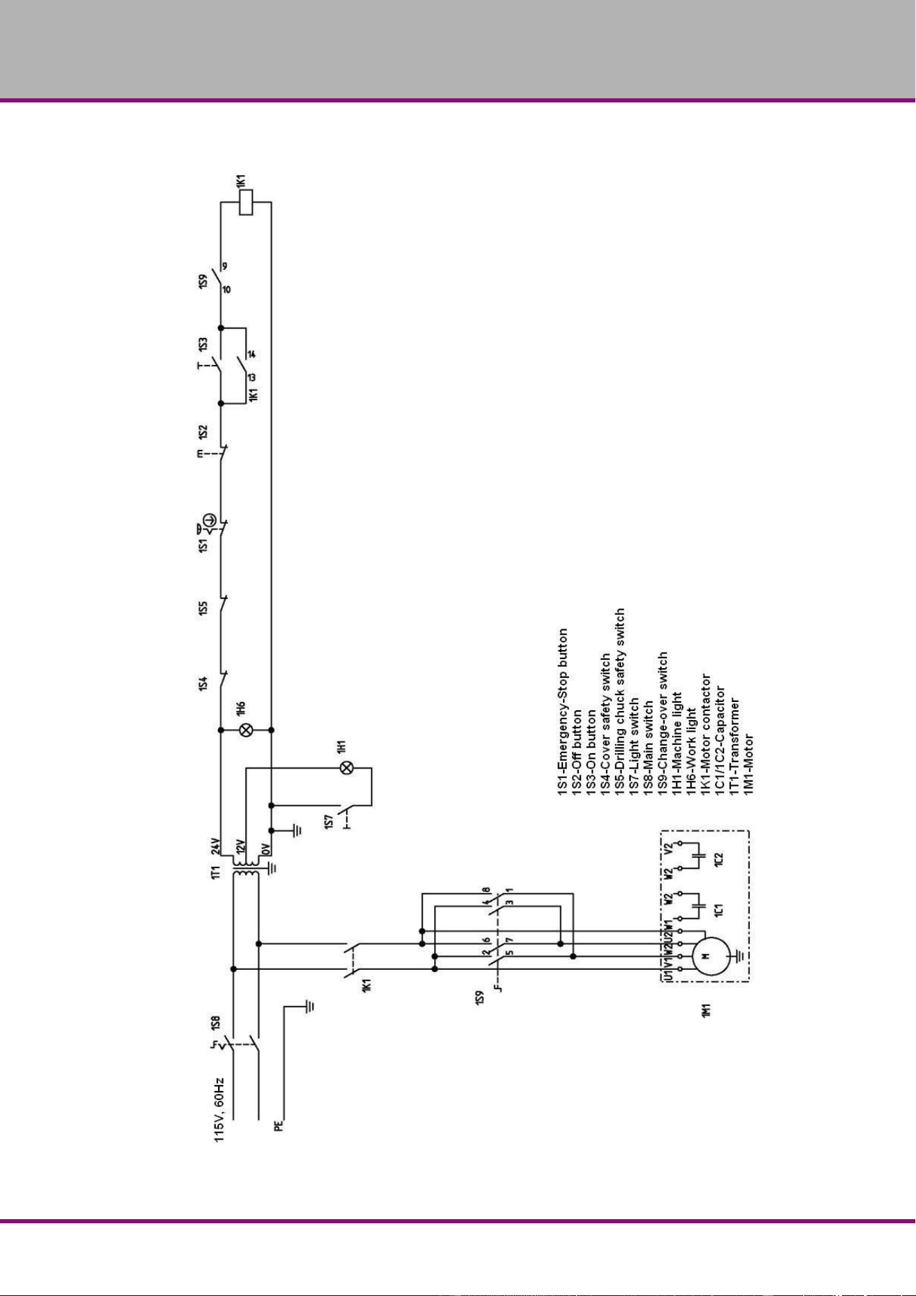
Page 59
B2
4H | B28H | B28HB | B28HV US
7.1.5 Wiring diagram B24H - 115V, 60 Hz
Fig.7-4: Wiring diagram B24H - 115V

Page 6
0
B24H | B28H | B28HB | B28HVUS
7.2 B28H | B28HB
7.2.1 Drilling head B28H | B28HB
Fig.7-5: Drilling head B28H | B28HB

Page 61
B24H
| B28H | B28HB | B28HV US
7.2.2 Column and drilling table B28H
Fig.7-6: Column and drilling table B28H

Page 6
2
B24H | B28H | B28HB | B28HVUS
7.2.3 Column and drilling table B28HB
Column and drilling table B28HB

Page 63
B2
4H | B28H | B28HB | B28HV US
7.2.4 Pulleys B28H | B28HB
Fig.7-7: Pulleys B28H

Page 6
4
B24H | B28H | B28HB | B28HVUS
7.2.5 Parts list B28H | B28HB
B28H, B28HB
Pos.
Description Qty. Size Item no.
1 Base 1 030202831
2 Column 1 030202832
2-1 Column B28HB 1 0302025202
3 Toothed rack 1 030202833
3-1 Toothed rack B28HB 1 0302025203
4 Toothed wheel 1 030202834
5 Drive screw 1 030202835
5-1 Distance plate 1 0302028351
6 Drill chuck 1 B16 030202836
6-1 Drill chuck (year on construction since 12/2009) 1 3050626
7 Spindle 1 030202837
7-1 Shaft 1 0302028371
8 V-belt 1 030202838
9 Spindle sleeve 1 030202839
9-1 Spring pin 1 5x40 0302028391
9-2 Bushing 1 0302028392
10 Socket head screw 4 M12x60 0302028310
10-1 Washer 4 GB/T93-1987-12 03020283101
10-2 Washer 4 GB/T97.1-1985-12 03020283102
12 Ball bearing 1 6206 0302028312
13 Distance plate 2 0302028313
14 Screw 1 JB-T7270.4-1994-2 0302028314
15 Grip 1 JB-T7270.4-1994-1 0302028315
15-1 Grip complete 1 JB-T7270.4-1994 03020283151
16 Crank 1 0302028316
17 Spindle sleeve feed grip old version 1 0302028317
17-1 Fixture sleeve handle 1 03020283171
17-2 Spindle sleeve handle 3 0302130332
18 Socket head screw 1 M5x20 0302028318
19 Washer 1 0302028319
19-1 Socket head screw 1 M16x90 03020283191
20 Bushing hup scalering 1 03020283201
20-1 Threaded pin 1 M6x6 0302028320
21 Scale ring 1 0302028321
22 Scale 1 0302028322
23 Clamping screw 1 0302028323
23-1 Socket head screw 2 M3x10 03020283231
23-2 Label „spans“ „release“ 1 03020283232
24 Bushing quick action grip 1 0302028324
24-1 Quick action grip 1 03020283241
25 Bolt 1 0302028325
25-1 Hexagonal nut 1 0302028325
26 hexagon bolt 4 M8x25 0302028326
26-1 Washer 4 GB/T93-1987-8 03020283261
26-2 Washer 4 GB/T97.1-1985-8 03020283262
27 Motor 1 0302028327
28 Feather key 1 6x6x20 0302028328
29 Socket head screw 3 M5x10 0302028329
29-1 Wash
er 2 5 03020283291
30 Belt housing base 1 0302028330
31 Pulley 1 0302028331
31-1 Threaded pin 1 03020283311
32 Belt housing upper part 1 0302028332
32-1 Socket head screw 6 M5x10 03020283321
34 Washer 1 0302028334
34-1 Feather key 1 03020283341
35 Plate closer 1 0302028335
36 Socket head screw 4 M6x15 0302028336
36-1 Washer 4 03020283361
36-2 Socket head screw 4 03020283362
36-3 Articulation 2 03020283363
36-4 Washer 12 03020283364
36-5 Hexagonal nut 12 03020283365
37 Spindle nut 1 0302028337
37-1 Ball bearing 1 6004-2Z 03020283371
37-2 Socket head screw 2 03020283372

Page 65
B2
4H | B28H | B28HB | B28HV US
38 Pulley 1 0302028338
39 Socket head screw 1 0302028339
40 Socket head screw 7 M6x15 0302028340
41 Motor plate 1 0302028341
42 Drilling head 1 0302028342
42-1 Washer 4 03020283421
42-2 Plate
1 03020283422
42-3 Socket head screw 4 M6x10 03020283423
42-4 Cable connection 2 03020283424
42-5 Bushing 1 03020283425
43 Spacer ring 1 0302028343
44 Ball bearing 2 6205-2R 0406205.2R
45 Circlip 2 DIN472 47x1.6 0302028345
46 Socket head screw 3 M4x10 0302028346
47 Covering plate 1 0302028347
48 Socket head screw 2 M6x30 0302028348
49 Fixing 1 0302028349
50 Knurled screw 1 M6x30 0302028350
50-1 Socket head screw 1 M5x10 03020283501
51 Alu- profile 1 20x20 0302028351
53 View sealing pane drill chuck protection 1 0302028353
53-1 Switch drill chuck 1 230V 0,5A 03020241531
55 Circlip 1 DIN471-12x1 0302028355
56 Box 1 0302028356
56-1 Spanner spiral spring 1 03020283561
56-2 Split pin 2 3x12 03020283562
57 Recuperating spring 1 0302028357
58 recuperating spring seat 1 0302028358
60 Switch plate 1 0302028360
60-1 Switch plate complete 1 03020241119
64 Socket head screw 4 M4x10 0302028364
65 Countersunk screw 2 M5x10 0302028365
66 O-ring 1 0302028366
66-1 Washer 1 03020283661
66-2 Spring 1 03020283662
67 Sliding block 1 0302028367
68 Setscrew 1 M8x15 0302028368
69 Machine illumination 1 0302028369
69-1 Lamp (diode) 1 12V 03020241691
70 Shank pinion 1 0302028370
70-1 Ring 1 03020283701
70-2 Socket head screw 2 M6x16 03020283702
70-3 Spring pin 1 03020283703
70-4 Mechanicel indicator scale 1 03020283704
71 Plate 1 0302028371
71-1 Socket head screw 4 M8x30 03020283711
72 Socket head screw 4 M10x25 0302028372
74 Oiler 1 0302028374
75 Clamping lever 1 0302028375
75-1 Washer 1 16 03020283751
76 Socket head screw 1 M6x20 0302028376
78 Clamping screw 1 M16x80 0302028378
79 Knurled screw 1 M8x20 0302028379
80 Sliding block 1 0302028380
81 Straight pin 1 6x40 0302028381
82 Oiler 2 0302028382
83 Distance plate 1 0302028383
83-1 Threaded pin 1 M6x6 03020283831
84 Key 1 8x8x18 0302028384
85 V-belt 1 0302028385
86 Knee piece 1 0302028386
87 Pulley 1 0302028387
90 Hexagon nut 1 M6 0302028390
92 Ball 1 0302028392
93 Feather 1 0302028393
94 Setscrew 1 M6x20 0302028394
95 Eejector 1 0302028395
97 Circlip 2 0302028397
97-1 Circlip 1 03020283971
B28H, B28HB
Pos.
Description Qty. Size Item no.

Page 6
6
B24H | B28H | B28HB | B28HVUS
98 Bearing 2 6203 0302028398
99 Ring 1 0302028399
99-1 Ring 1 03020283991
100 Setscrew 1 M8x15 03020283100
100-1 Setscrew 1 M8x15 030202831001
101 Washer 1 03020283101
102 Socket head screw 1 M6x20 03020283102
103 Bush button On 1 230V 5A 03020283103
104 Bush button Off 1 230V 5A 0302024185
105 main switch 1 660V 20A 0302024187
106 switch for direction of rotation 1 03020283106
107 light switch 1 250V 6A 03020283107
108 emergency -stop switch 1 600V 10A 0302024190
109 Nut 4 M4 03020283109
110 Counterpart reed contact 1 03020283110
111 Reed contact 1 PS-3150 03020283111
112 Socket head screw 4 M3x10 03020283112
113 Groove nut 1 M24x1,5 03020283113
114 Drilling machine table 1 03020283114
115 Circlip 1 03020283115
116 Cable discharge 1 0302024198
0 Transformer (without illustration) 1 0302024196
0 Contactor (without illustration) 1 230V 16A 0302024197
B28H, B28HB
Pos.
Description Qty. Size Item no.

Page 67
B2
4H | B28H | B28HB | B28HV US
7.3 B28HV
7.3.1 Drilling head B28HV
Fig.7-8: Drilling head B28HV

Page 68
B24
H | B28H | B28HB | B28HVUS
7.4 Column and drilling table B28HV
Fig.7-9: Column and drilling table B28HV

Page 69
B2
4H | B28H | B28HB | B28HV US
7.4.1 Pulleys B28HV
Fig.7-10: Pulleys B28HV

Page 7
0
B24H | B28H | B28HB | B28HVUS
7.4.2 Parts list B28HV
B28HV
Pos.
Description Qty. Size Item no.
117 Plate closer 1 03020285117
118 Belt housing base 1 03020285118
119 Threaded pin 1 03020285119
120 Pulley 1 03020285120
121 V-belt 1 03020285121
122 Socket head screw 3 M5x10 03020285122
123 Washer 3 5 03020285123
124 Belt housing upper part 1 03020285124
125 Socket head screw 6 M5x10 03020285125
126 Nut 4 M3 03020285126
127 Counterpart reed contact 1 03020285127
128 V-belt 1 03020285128
129 Socket head screw 4 M3x10 03020285129
130 Circlip 1 03020285130
131 Circlip 1 03020285131
132 Bearing 1 6203 03020285132
133 Bearing 1 6203 03020285133
134 Pulley 1 03020285134
135 Knee piece 1 03020285135
136 Feather key 1 03020285136
137 Socket head screw 1 03020285137
138 Washer 1 03020285138
139 Groove nut 1 M24x1,5 03020285139
140 Pulley 1 03020285140
141 Hexagonal nut 12 03020285141
142 Washer 12 03020285142
143 Articulation 2 03020285143
144 Washer 1 03020285144
145 Socket head screw 4 M6x15 03020285145
146 Washer 4 03020285146
147 Socket head screw 4 03020285147
148 Socket head screw 4 03020285148
149 Reed contact 1 PS-3150 03020285149
150 Socket head screw 3 M5x10 03020285150
151 Washer
2 5 03020285151
155 Washer 1 03020285155
156 Socket head screw 1 03020285156
157 Spindle sleeve feed grip old version 1 03020285157
157-1 Fixture sleeve handle 1 03020283171
157-2 Spindle sleeve handle 3 0302130332
158 Plastic handhold old version 3 03020285158
159 Quick action grip 1 03020285159
160 Clamping screw 1 03020285160
161 Setscrew 1 M8x15 03020285161
162 Cable connection 2 03020285162
163 Scale ring 1 03020285163
164 Knurled screw 1 M8x20 03020285164
165 Bushing quick action grip 1 03020285165
166 Sliding block 1 03020285166
167 Label „spans“ „release“ 1 03020285167
168 Socket head screw 2 M3x10 03020285168
169 Hexagonal nut 1 03020285169
170 Bolt 1 03020285170
171 Socket head screw 6 M3x8 03020285171
172 Cover motor 1 03020285172
173 Flange motor 1 03020285173
174 Socket head screw 6 M6x55 03020285174
175 Cover drilling head 1 03020285175
176 Cover 1 03020285176
177 Brushlesscontroller 1 03020285177
177-1 Trafo 1 030202451771
177-2 EMV-Filter 1 030202451772
178 Socket head screw 3 M4x20 03020285178
179 Feather key 1 03020285179
180 Washer 4 03020285180
181 Drilling head 1 03020285181
182 Spacer ring 1 03020285182

Page 71
B2
4H | B28H | B28HB | B28HV US
183 Shaft 1 03020285183
184 Circlip 2 DIN472 47x1.6 03020285184
185 Ball bearing 1 6205-2R 0406205.2R
186 Ball bearing 1 6005 03020285186
187 Circlip 2 DIN472 47x1.6 03020285187
188 Bushing 1 03020285188
189 main switch 1 660V 20A 03020285189
190 Socket head screw 1 03020285190
191 Socket head screw 7 M6x15 03020285191
192 Light switch ON/ OFF 1 250V 6A 03020285192
193 Socket head screw 3 03020285193
194 Covering plate 1 03020285194
195 Circlip 1 DIN471-12x1 03020285195
196 Box 1 03020285196
197 Recuperating spring 1 03020285197
198 Ejector 1 03020285198
199 Spring 1 03020285199
200 Ball 1 03020285200
201 Digital display 1 03020285201
202 Cooling pump switch ON/ OFF 1 250V 6A 03020285202
203 switch for direction of rotation 1 03020285203
204 Switch plate 1 03020285204
205 Potentiometer 1 03020285205
206 Socket head screw 4 M4x10 03020285206
207 emergency -stop switch 1 600V 10A 03020285207
208 Switch ON/OFF 1 03020285208
209 Connector electric supply 1 03020285209
210 Countersunk screw 2 M5x10 03020285210
211 Alu- profile 1 20x20 03020285211
212 Socket head screw 2 M6x30 03020285212
213 Socket head screw 1 M5x10 03020285213
214 Spanner spiral spring 1 03020285214
215 Split pin 2 3x12 03020285215
216 Bushing 1 03020285216
217 Setscrew 1 M6x20 03020285217
218 Hexagon nut 1 M6 03020285218
219 Rotation speed sensor 1 03020285219
220 Holder 1 03020285220
221 Machine illumination 1 03020285221
222 Hexagonal nut 2 03020285222
223 Sliding block 1 03020285223
224 View sealing pane drill chuck protection 1 03020285224
225 Spring 1 03020285225
226 Washer 1 03020285226
227 Ball bearing 1 6206 03020285227
228 Spring pin 1 5x40 03020285228
229 Spindle sleeve 1 03020285229
230 O-ring 1 03020285230
231 Bushing 1 03020285231
232 Ball bearing 1 6004-2Z 03020285232
233 Shank pinion 1 03020285233
234 Spindle nut 1 03020285234
235 Socket head screw 2 03020285235
236 Key 1 8x8x18 03020285236
237 Mechanicel indicator scale 1 03020285237
238 Ring 1 03020285238
239 Spring pin 1 03020285239
240 Socket head screw 2 M6x16 03020285240
241 Scale 1 03020285241
242 Straight pin 1 6x40 03020285242
243 Bushing hup scalering 1 03020285243
244 Key 1 03020285244
245 Spindle 1 03020285245
246 Drill chuck 1 3050626
246-1 Drill chuck (year on construction since 12/2009) 1 3050573
B28HV
Pos.
Description Qty. Size Item no.

Page 7
2
B24H | B28H | B28HB | B28HVUS
247 Motor 1
230V 1.5 kW
MBL-123HM-300HA-L
Hall Sensor 240°
9.5 amps
03020285247
248 Socket head screw 4 M8x25 03020285248
250 Base 1 03020285250
251 Plate coolant reservoir 1 03020285251
252 Washer 1 8 03020285252
253 Socket head screw 1 M8x12 03020285253
254 Coolant hose 1 03020285254
255 Washer 4 GB97.1-85-10 Socket head screw
256 Washer 4 GB93-87-10 03020285256
257 Socket head screw 4 M10x40 03020285257
258 Distance plate 1 03020285258
259 Toothed wheel 1 03020285259
260 Distance plate 1 03020285260
261 Drive screw 1 03020285261
262 Hose clip 2 03020285262
263 Setscrew 1 M8x15 03020285263
264 Toothed rack 1 03020285264
265 Screw 1 JB-T7270.4-1994-2 03020285265
266 Grip 1 JB-T7270.4-1994-1 03020285266
266-1 Grip complete 1 JB-T7270.4-1994 030202852661
267 Distance plate 1 03020285267
268 Threaded pin 1 M6x6 03020285268
269 Crank 1 03020285269
270 Socket head screw 1 M6x20 03020285270
271 Shaft 1 03020285271
272 Oiler 1 03020285272
273 Socket head screw 1 M16x90 03020285273
274 Clamping lever 1 03020285274
275 Washer 1 16 03020285275
276 Clamping screw 1 03020285276
277 Oiler 2 03020285277
278 Setscrew 1 M8x15 03020285278
279 Ring 1 03020285279
280 Drilling machine table 1 03020285280
281 Coolant hose 1 03020285281
282 Holder 1 03020285282
283 Ball valve 1 03020285283
284 Flexible coolant hose 1 03020285284
285 Clamping screw 1 M6x12 03020285285
286 Hexagon socket screw 2 M6x14 03020285286
287 Ring 1 03020285287
288 Socket head screw 4 M8x30 03020285288
289 Plate 1 03020285289
290 Socket head screw 4 M10x25 03020285290
291 Hose clamp 4 03020285291
292 Column 1 03020285292
293 Coolant hose 1 03020285293
294 Hose clip 1 03020285294
295 Socket head screw 1 M6x10 03020285295
296 Washer 1 GB97.1-85-6 03020285296
297 Coolant pump 1 03020285297
298 Circlip 1 03020285298
299 Pump relay 1 03020285299
300 Cable discharge 1 0302024198
B28HV
Pos.
Description Qty. Size Item no.
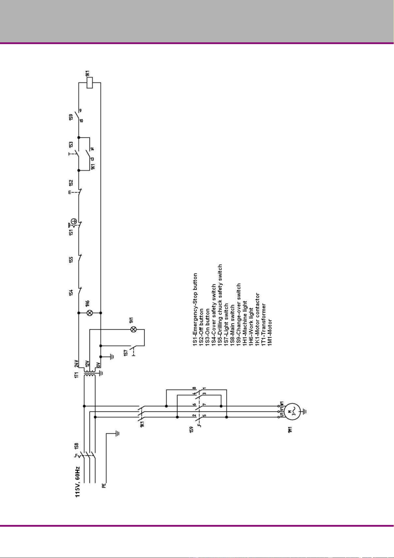
Page 73
B2
4H | B28H | B28HB | B28HV US
7.4.3 Wiring diagram B28H | B28HB - 115V, 60Hz
Fig.7-11: Wiring diagram B28H - 400V
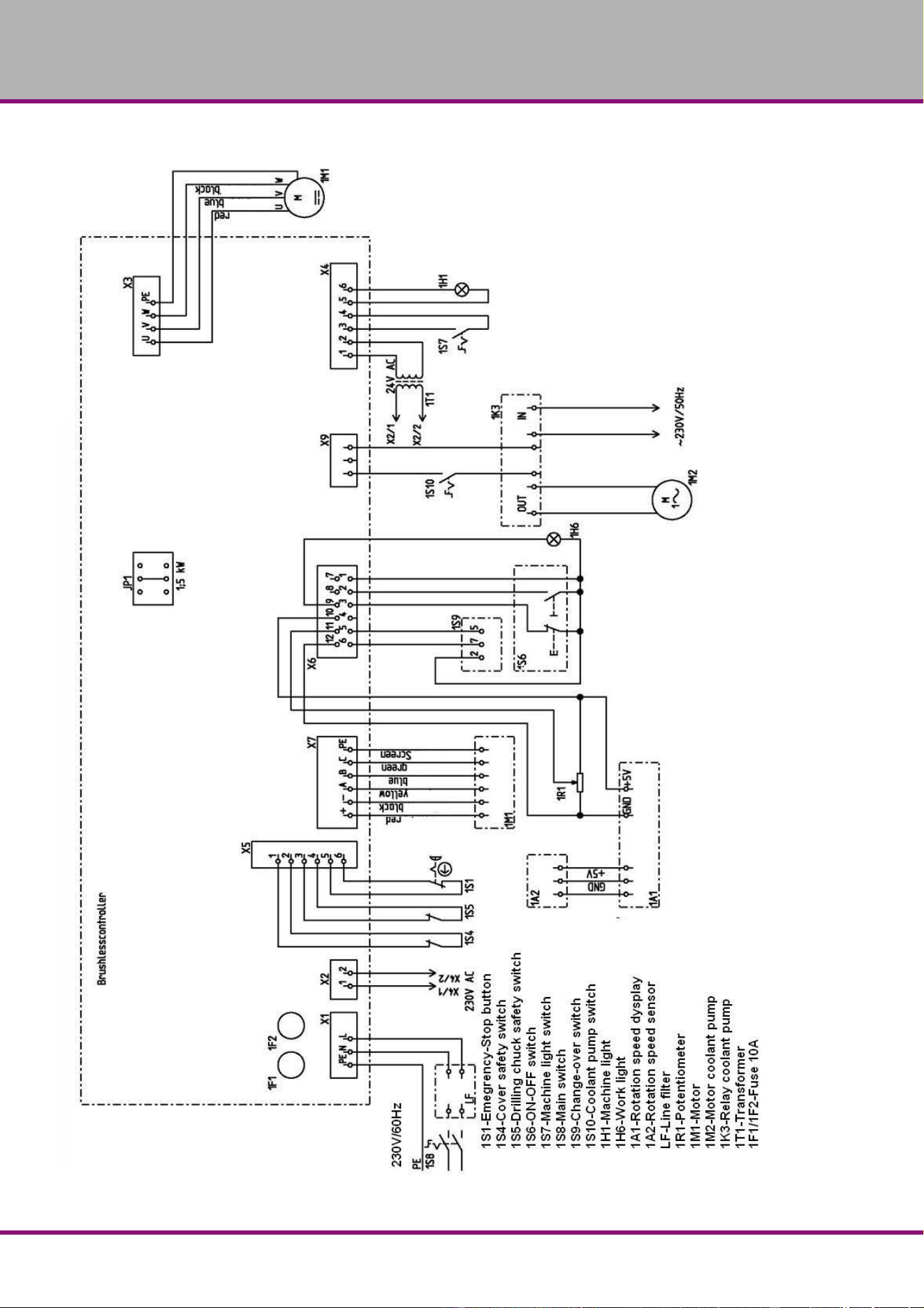
Page 7
4
B24H | B28H | B28HB | B28HVUS
7.4.4 Wiring diagram B28HV, page 1 - 230V, 60Hz
Fig.7-12: Wiring diagram B28HV

Page 75
B2
4H | B28H | B28HB | B28HV US
7.4.5 Wiring diagram B28HV, page 2 - 230V, 60Hz
Fig.7-13: Wiring diagram B28HV

Page 7
6
B24H | B28H | B28HB | B28HVUS
8 Troubleshooting
Problem Cause / possible effects Solution
FI protective switch on
machines with frequency con-
verter triggers.
• an unusual FI protective switch is
being used
• "Power supply“ on page 33
Motor gets hot • wrong power supply
Noise during working • Spindle turning dry
• Tool blunt or is being incorrectly
secured
• Grease spindle (only in the disman-
tled condition possible)
• Use new tool and check securing
(fixed setting of the bit, drill chuck
and morse taper).
Bit „burnt“ • bit speed too high/too much feed
• The chips have not been removed
from the bore hole
• Bit dull
• no or too little cooling
• Select another speed
• Extract the bit more often
• Sharpen or replace bit
• Use coolant.
Bit tip moves, bore hole is not
circular
• hard part on the work piece
• Unequal length of the cutting spiral
or angles in the bit.
• Bit deformed
• Replace bit
Defective bit • No support used. • Use a wooden board and secure it to
the work piece
Bit running off-centre or „hop-
ing“
• Bit deformed
• spindle bearing worn out
• Bit badly secured.
• Drill chuck defective.
• Replace bit
• replace spindle bearing
• Secure the bit properly
• Replace the drill chuck
Impossible to introduce drill
chuck or morse taper
• There is dirt, grease or oil on the
inner conical surface of the drill
chuck or on the conical surface of
the drill spindle
• Clean surfaces well
• Keep surfaces fat free
Motor does not start • motor badly connected
• Defective fuse
• Have it checked by authorized per-
sonnel
Overheating of motor and lack
of power
• motor overloaded
• Insufficient mains voltage
• motor badly connected
• Reduce feed, disconnect if
necessary
• Have it checked by authorized per-
sonnel
Precision of the work deficient • Heavy and unbalanced or twisted
work piece
• Balance work piece statically and
secure it without straining
• Adjust work piece holder
Drill spindle does not return to
its initial position
• Failure of spindle return spring
• Locking bolt inserted
• Check spindle return spring and
replace if necessary
• Remove locking bolt
Impossible to move the drill
spindle sleeve downwards.
• Locking bolt inserted
• Drill depth adjustment no released
• Pull out the locking bolt
• Release drill depth adjustment
Spindle bearings overheating • Bearing worn down
• Excessive prior tension of the
bearing
• Working at high rate for a long time
• Replace
• Reduce bearing slack for fixed
bearing (conical-roller bearing)
• Reduce bit speed/feed

Page 77
B2
4H | B28H | B28HB | B28HV US
Working spindle rattling on
rough piece surfaces
• Excessive slack in bearing
• Working spindle goes up and down
• Adjustment strip loose
• Chuck loose
• Tool blunt
• Piece loose
• Reduce bearing slack or replace
bearing
• Readjust bearing slack (fixed
bearing)
• Adjust strip to the correct slack using
the adjusting screw
• Check, re-tighten
• Sharpen or replace tool
• Secure the piece properly
Problem Cause / possible effects Solution

Page 7
8
B24H | B28H | B28HB | B28H VarioUS
9 Appendix
9.1 Copyright
This documentation is copyright. All derived rights are also reserved, especially those of trans-
lation, re-printing, use of figures, broadcast, reproduction by photo-mechanical or similar means
and recording in data processing systems, neither partial nor total.
The company reserves the right to make technical alternations without prior notice.
9.2 Terminology/Glossary
Term Explanation
Drift Tool for removing the bit or the drill chuck from the drill spindle
Drill chuck Fixture for holding the bit
Drill head Upper part of the bench drill and upright drill
Drill sleeve Fixed hollow shaft which runs in the drill spindle
Drill spindle Shaft activated by the motor
Drilling table Support surface, clamping surface
Keyless drill chuck Manually tightenable bit holding fixture
Morse taper Taper of the bit or drill chuck
Spindle lever Manual control for the drill fee
Tool Milling cutter, drill bit, countersink, etc.
Workpiece Piece to be drilled or machined

Page 84
B24H | B28H | B28HB | B28HVUS
Index
A
Accident report ..................................................... 15
Assembly
.............................................................. 23
Drilling machine table B24H (B28HB)
............. 27
Drilling machine table B28H (Vario)
................ 27
C
Classification of hazards ........................................ 6
Copyright
.............................................................. 78
Cutting speeds
..................................................... 46
D
Dimensions .......................................................... 20
Dimensions B24H
................................................ 19
Dimensions B28H
................................................ 21
Dimensions B28H Vario
....................................... 22
Dimensions B28HB
.............................................. 20
Drill depth stop
..................................................... 41
Drilling capacity
.................................................... 16
Drilling machine table
........................................... 16
E
Electrical ............................................................... 15
EMERGENCY-STOP button
................................ 12
Emissions
............................................................. 17
Environmental conditions
..................................... 17
F
First use ............................................................... 33
I
Inspection ............................................................. 50
L
LIMITED WARRANTY ......................................... 79
M
Maintenance ......................................................... 50
O
Obligations
Operator
............................................................ 9
User
................................................................ 10
Operating material
................................................ 17
Other pictograms
.................................................... 7
P
Power connection ................................................. 16
Power supply
........................................................ 33
Proper use
.............................................................. 8
Q
Qualification of employees ..................................... 9
R
Required space .................................................... 17
S
Safety
during maintenance
........................................ 14
Safety devices
...................................................... 10
Safety warnings
...................................................... 6
Scope of delivery
.................................................. 23
Speed table
B24H
............................................................... 40
B28H
................................................................41
B28H (B)
..........................................................40
B28HVario
.......................................................40
Speeds
..................................................................17
Spindle
..................................................................16
Storage
.................................................................24
T
Table cutting speeds .............................................46
Table cutting speeds / infeed
................................46
Technical data
......................................................16
Transport
..............................................................23
Troubleshooting
....................................................76
W
Warnings .................................................................6
