Loading ...
Loading ...
Loading ...
NOTE:Remove the battery if exposed to prolonged
periods of sub-freezing temperatures. Store in a cool dry
location where temperatures are above freezing.
5. Lubricate all lubrication points.
NOTE: We do not recommend the use of apressure washer or
garden hose to clean your tractor. They may cause damage
to electrical componen ts;spindles; pulleys; bearings; or the
engine. The use of water will result in shortened life and
reduce serviceability.
RemovingTheTractorFromStorage
• Check the engine oil.
• Fully charge the battery and inflate the tires to the
recommended pressure.
• If drained before storing, fill the fuel tank with clean,
fresh gasoline.
• Add clean, fresh fuel.
• Start the engine and allow to idle for a few minutes to
ensure engine is operating properly.
• Drive the tractor without a load to make certain all the
tractor systems are functioning properly.
Adjustments
_ ARNING! Shut the engine off, remove the
ignition key and engage the parking brake
before making adjustments. Protect your
hands by using heavy gloves when handling
the blades.
Adjusting the Operators Seat
• To adjust the position of the seat, move and hold the
seat adjustment lever toward the left. Slide the seat
forward or rearward to the desired position; then
release the adjustment lever. Make sure seat is locked
into position before operating the tractor. See Figure
6-5.
/-
Seat
J
Move Lever
-to Left
Adjustment
Lever
Figure 6-5
AdjustingRH& LHDriveControlLevers
The RH and LH drive control levers can be adjusted up or
down and fore-and-aft for the comfort of the operator. The
drive control levers can be placed in either of two height
positions, and/or can be moved forward or rearward
within the range of the slot in each control lever mounting
bracket.
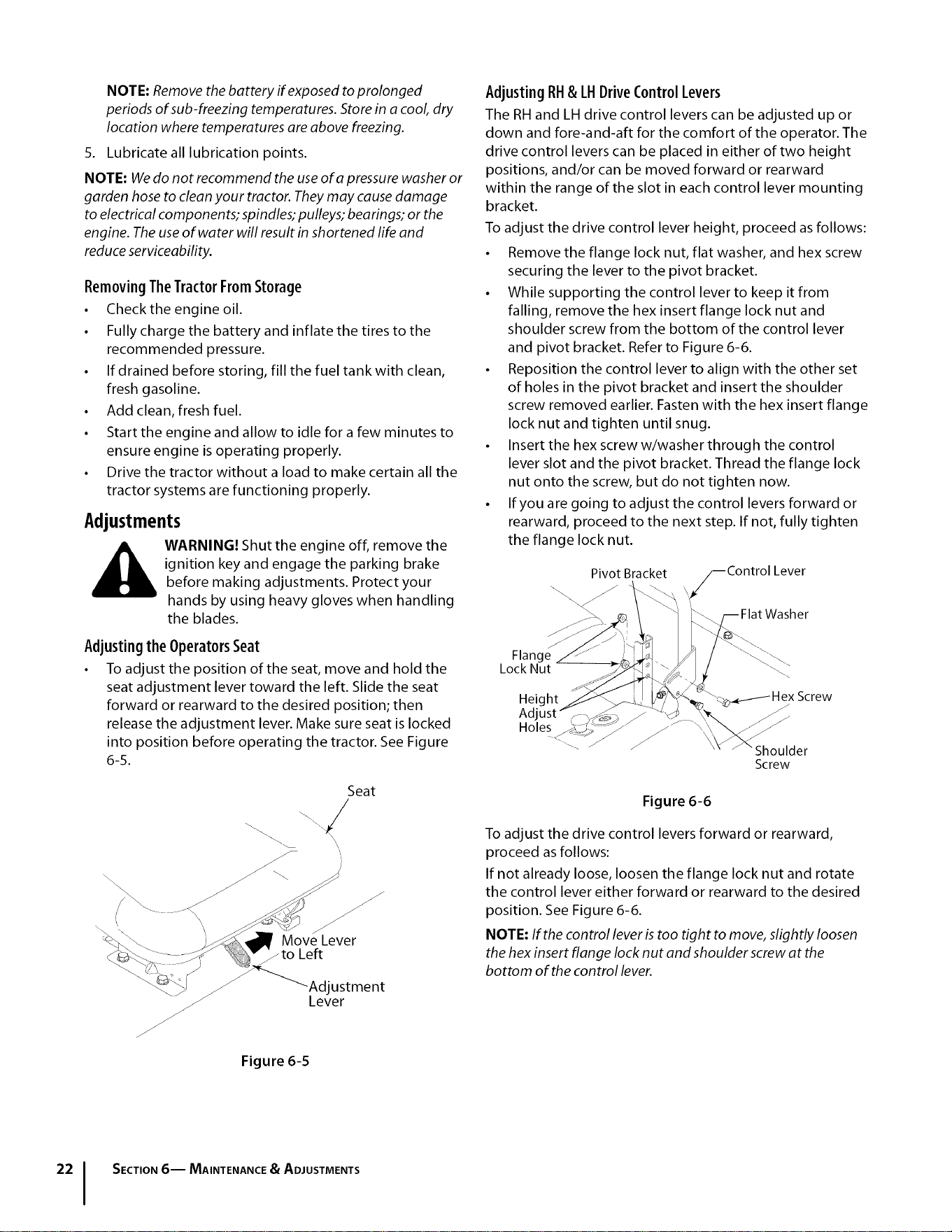
To adjust the drive control lever height, proceed asfollows:
• Remove the flange lock nut, flat washer, and hex screw
securing the lever to the pivot bracket.
• While supporting the control lever to keep it from
falling, remove the hex insert flange lock nut and
shoulder screw from the bottom of the control lever
and pivot bracket. Refer to Figure 6-6.
• Reposition the control lever to align with the other set
of holes in the pivot bracket and insert the shoulder
screw removed earlier. Fasten with the hex insert flange
lock nut and tighten until snug.
• Insert the hex screw w/washer through the control
lever slot and the pivot bracket. Thread the flange lock
nut onto the screw, but do not tighten now.
• If you are going to adjust the control levers forward or
rearward, proceed to the next step. If not, fully tighten
the flange lock nut.
Pivot Bracket /--Control Lever
/
Flange
Lock Nut
Figure 6-6
To adjust the drive control levers forward or rearward,
proceed as follows:
If not already loose, loosen the flange lock nut and rotate
the control lever either forward or rearward to the desired
position. See Figure 6-6.
NOTE: If the control lever is too tight to move, slightly loosen
the hex insert flange lock nut and shoulder screw at the
bottom of the control lever.
SECTION6-- MAINTENANCE & ADJUSTMENTS
Loading ...
Loading ...
Loading ...