Loading ...
Loading ...
Loading ...
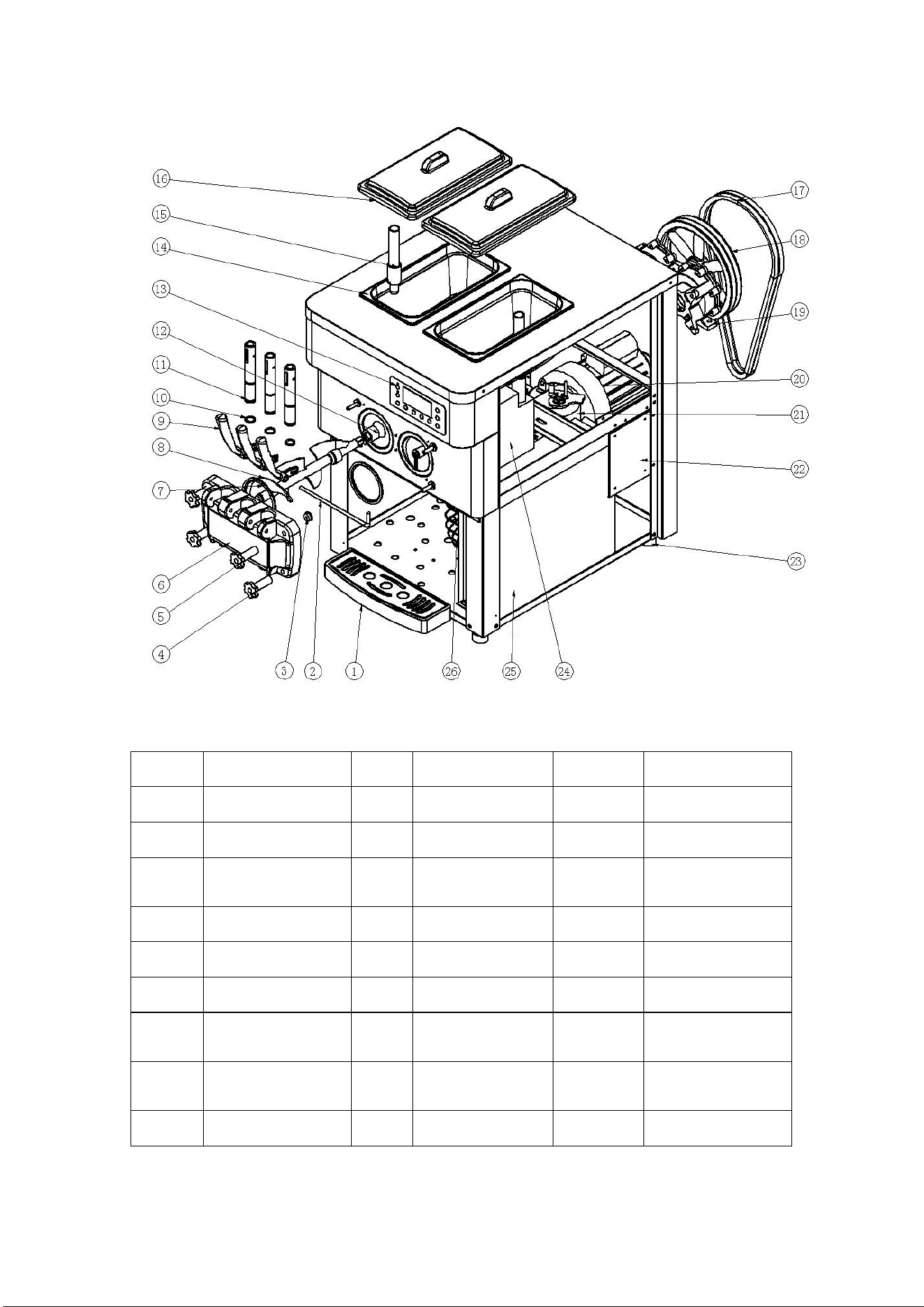
II. Structure diagram of table type
(3)
No.
Name
No.
Name
No.
Name
1
Water receiver
10
Piston seal
19
Reducer
2
Handle steady pin
11
Piston
20
Stirring motor
3
Supporting sheath
of stirring shaft
12
Bellmouth seal
21
Compressor
4
Lower fixing nut
13
Operating panel
22
Control panel
5
Upper fixing nut
14
Material cylinder
23
Floor mat
6
Liquid outlet valve
15
Puffing tube
24
Evaporator
7
Seal for liquid
outlet valve
16
Cylinder cover
25
Condenser
8
Stirring shaft
17
Belt
26
Draught fan
9
Handle
18
Belt pulley
Loading ...
Loading ...
Loading ...