Loading ...
Loading ...
Loading ...

①
②
④
⑤
⑥
⑧ ⑦⑨
③
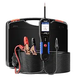
2.2 Tool Description
①
Probe Tip - Contacts the circuit or component to be tested.
②
Head Lights - llluminates dark work areas or work areas at night.
③
LCD Display - Indicates test results.
④
Red/Green Polarity Indicator - Identifies positive, negative or open circuits. The
RED indicator lights up when the Probe Tip is contacting a positive circuit. The GREEN
indicator lights up when the Probe Tip is contacting a negative circuit.
⑤
Power Switch - Allows you to conduct a positive or negative battery current to
the tip for activating and testing the function of electrical components.
⑥
Mode Button - Selects the work mode: AC Voltage, DC Voltage, Resistance, Diode.
⑦
Auxiliary Ground Lead - Assists test as a ground lead.
⑧
Adaptor - Connects to the battery.
⑨
Loudspeaker - Alert prompt.
Loading ...
Loading ...
Loading ...