Loading ...
Loading ...
Loading ...
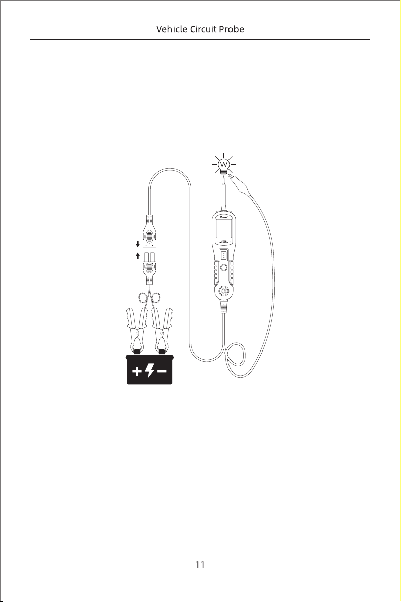
Figure 11
provide power to your component. With the power switch pushed forward, power
will flow from the positive lead on the battery to the probe tip, then to the compo-
nent’s positive terminal, through the component, through the auxiliary ground lead,
then back to the tool, and all the way back to the vehicle’s battery’s ground.
(Figure 11)
(1) Press the power switch forward to activate the bulb.
(2) Contact the tip to the positive terminal of the bulb.
(3) Connect the negative auxiliary clip.
3.5 Activating Components in The Vehicle
While the tool in DC Voltage mode, contact the probe tip to the positive terminal of the
component, the green LED should light up, indicating continuity to ground. While
observing the green LED. Quickly press the power switch button forward and release,
if the green LED went out and the read LED comes on, you may proceed with further
If the green LED went off at that instant or if the circuit breaker tripped, the tool has
been overloaded. This could happen for the following reasons:
◆ The contact you are probing is direct ground or negative voltage.
◆ The component you are testing is short-circuited.
◆ The component is a very high current component (i.e., starter motor).
If the circuit breaker is tripped, reset it by waiting for it to cool down (15 sec.)
Loading ...
Loading ...
Loading ...