
TC-MS 2112
Art.-Nr.: 43.002.95 I.-Nr.: 11025
1
D Originalbetriebsanleitung
Kapp- und Gehrungssäge
GB Original operating instructions
Crosscut and miter saw
F Mode d’emploi d’origine
Scie à onglet
I Istruzioni per l’uso originali
Sega per troncature e tagli obliqui
S Original-bruksanvisning
Kap- och geringssåg
CZ Originální návod k obsluze
Kapovací pila
SK Originálny návod na obsluhu
Kapovacia píla
Anl_TC_MS_2112_SPK1.indb 1Anl_TC_MS_2112_SPK1.indb 1 12.08.15 09:4612.08.15 09:46
- 2 -
1
2
20
9
7
4
14
3
20
14
8 22
17
13
20
21
26
1
2 3
21
10
11
12
5
6
d
c
20
16
15
23
Anl_TC_MS_2112_SPK1.indb 2Anl_TC_MS_2112_SPK1.indb 2 12.08.15 09:4612.08.15 09:46
- 3 -
4 5
6 7
8 9
32
18
13
29
4
c
z
f
d
31
8 a 5
7
16
28 12 19
28
8
5
Anl_TC_MS_2112_SPK1.indb 3Anl_TC_MS_2112_SPK1.indb 3 12.08.15 09:4612.08.15 09:46
- 4 -
10 11
12 13
19
5
7
8
b
30
Anl_TC_MS_2112_SPK1.indb 4Anl_TC_MS_2112_SPK1.indb 4 12.08.15 09:4612.08.15 09:46

D
- 5 -
Inhaltsverzeichnis
1. Sicherheitshinweise
2. Gerätebeschreibung und Lieferumfang
3. Bestimmungsgemäße Verwendung
4. Technische Daten
5. Vor Inbetriebnahme
6. Betrieb
7. Austausch der Netzanschlussleitung
8. Reinigung, Wartung und Ersatzteilbestellung
9. Entsorgung und Wiederverwertung
10. Lagerung
Anl_TC_MS_2112_SPK1.indb 5Anl_TC_MS_2112_SPK1.indb 5 12.08.15 09:4612.08.15 09:46

D
- 6 -
Gefahr! - Zur Verringerung des Verletzungsrisikos Bedienungsanleitung lesen
Vorsicht! Tragen Sie einen Gehörschutz. Die Einwirkung von Lärm kann Gehörverlust bewirken.
Vorsicht! Tragen Sie eine Schutzbrille. Während der Arbeit entstehende Funken oder aus dem Gerät
heraustretende Splitter, Späne und Stäube können Sichtverlust bewirken.
Vorsicht! Tragen Sie eine Staubschutzmaske. Beim Bearbeiten von Holz und anderer Materialien
kann gesundheitsschädlicher Staub entstehen. Asbesthaltiges Material darf nicht bearbeitet werden!
Vorsicht! Verletzungsgefahr! Nicht in das laufende Sägeblatt greifen.
Anl_TC_MS_2112_SPK1.indb 6Anl_TC_MS_2112_SPK1.indb 6 12.08.15 09:4612.08.15 09:46

D
- 7 -
Gefahr!
Beim Benutzen von Geräten müssen einige Si-
cherheitsvorkehrungen eingehalten werden, um
Verletzungen und Schäden zu verhindern. Lesen
Sie diese Bedienungsanleitung / Sicherheitshin-
weise deshalb sorgfältig durch. Bewahren Sie die-
se gut auf, damit Ihnen die Informationen jederzeit
zur Verfügung stehen. Falls Sie das Gerät an an-
dere Personen übergeben sollten, händigen Sie
diese Bedienungsanleitung / Sicherheitshinweise
bitte mit aus. Wir übernehmen keine Haftung für
Unfälle oder Schäden, die durch Nichtbeachten
dieser Anleitung und den Sicherheitshinweisen
entstehen.
1. Sicherheitshinweise
Die entsprechenden Sicherheitshinweise fi nden
Sie im beiliegenden Heftchen!
Gefahr!
Lesen Sie alle Sicherheitshinweise und An-
weisungen. Versäumnisse bei der Einhaltung der
Sicherheitshinweise und Anweisungen können
elektrischen Schlag, Brand und/oder schwere
Verletzungen verursachen. Bewahren Sie alle
Sicherheitshinweise und Anweisungen für
die Zukunft auf.
2. Gerätebeschreibung und
Lieferumfang
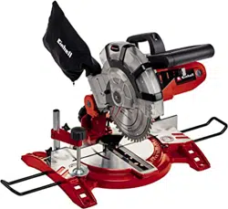
2.1 Gerätebeschreibung (Bild 1/2)
1. Entriegelungshebel
2. Handgriff
3. Ein-/ Ausschalter
4. Maschinenkopf
5. Sägeblatt
6. Sägeblattschutz beweglich
7. Anschlagschiene
8. Drehtisch
9. Bodenplatte feststehend
10. Rändelschraube
11. Zeiger
12. Spannschraube
13. Sägewellensperre
14. Spänesack
15. Skala
16. Sicherungsbolzen
17. Skala (Drehtisch)
18. Einstellschraube 0°
19. Einstellschraube 45°
20. Werkstückaufl age
21. Spannvorrichtung
22. Tischeinlage
23. beweglicher Anschlag, tischwinkelabhängig
2.2 Lieferumfang
Bitte überprüfen Sie die Vollständigkeit des Arti-
kels anhand des beschriebenen Lieferumfangs.
Bei Fehlteilen wenden Sie sich bitte spätestens
innerhalb von 5 Arbeitstagen nach Kauf des Arti-
kels unter Vorlage eines gültigen Kaufbeleges an
unser Service Center oder an die Verkaufstelle,
bei der Sie das Gerät erworben haben. Bitte
beachten Sie hierzu die Gewährleistungstabelle
in den Service-Informationen am Ende der An-
leitung.
•
Öffnen Sie die Verpackung und nehmen Sie
das Gerät vorsichtig aus der Verpackung.
•
Entfernen Sie das Verpackungsmaterial so-
wie Verpackungs-/ und Transportsicherungen
(falls vorhanden).
•
Überprüfen Sie, ob der Lieferumfang vollstän-
dig ist.
•
Kontrollieren Sie das Gerät und die Zubehör-
teile auf Transportschäden.
•
Bewahren Sie die Verpackung nach Möglich-
keit bis zum Ablauf der Garantiezeit auf.
Gefahr!
Gerät und Verpackungsmaterial sind kein
Kinderspielzeug! Kinder dürfen nicht mit
Kunststoff beuteln, Folien und Kleinteilen
spielen! Es besteht Verschluckungs- und Er-
stickungsgefahr!
•
Kapp,- und Gehrungssäge
•
Hartmetallbestücktes Sägeblatt
•
Inbusschlüssel (c, d)
•
Spänefangsack (14)
•
Werkstückauflage (20)
•
Spannvorrichtung (21)
•
Originalbetriebsanleitung
•
Sicherheitshinweise
Anl_TC_MS_2112_SPK1.indb 7Anl_TC_MS_2112_SPK1.indb 7 12.08.15 09:4612.08.15 09:46

D
- 8 -
3. Bestimmungsgemäße
Verwendung
Die Kapp- und Gehrungssäge dient zum Kappen
von Holz und holzähnlichen Werkstoff en, entspre-
chend der Maschinengröße. Die Säge ist nicht
zum Schneiden von Brennholz geeignet.
Die Maschine darf nur nach ihrer Bestimmung
verwendet werden. Jede weitere darüber hinaus-
gehende Verwendung ist nicht bestimmungsge-
mäß. Für daraus hervorgerufene Schäden oder
Verletzungen aller Art haftet der Benutzer/Bedie-
ner und nicht der Hersteller.
Bitte beachten Sie, dass unsere Geräte bestim-
mungsgemäß nicht für den gewerblichen, hand-
werklichen oder industriellen Einsatz konstruiert
wurden. Wir übernehmen keine Gewährleistung,
wenn das Gerät in Gewerbe-, Handwerks- oder
Industriebetrieben sowie bei gleichzusetzenden
Tätigkeiten eingesetzt wird.
Es dürfen nur für die Maschine geeignete Säge-
blätter verwendet werden. Die Verwendung von
Trennscheiben aller Art ist untersagt.
Bestandteil der bestimmungsgemäßen Verwen-
dung ist auch die Beachtung der Sicherheitshin-
weise, sowie die Montageanleitung und Betriebs-
hinweise in der Bedienungsanleitung.
Personen, die die Maschine bedienen und war-
ten, müssen mit dieser vertraut und über mögli-
che Gefahren unterrichtet sein. Darüber hinaus
sind die geltenden Unfallverhütungsvorschriften
genauestens einzuhalten. Sonstige allgemeine
Regeln in arbeitsmedizinischen und sicherheits-
technischen Bereichen sind zu beachten.
Veränderungen an der Maschine schließen eine
Haftung des Herstellers und daraus entstehende
Schäden gänzlich aus. Trotz bestimmungsgemä-
ßer Verwendung können bestimmte Restrisiko-
faktoren nicht vollständig ausgeräumt werden.
Bedingt durch Konstruktion und Aufbau der Ma-
schine können folgende Punkte auftreten:
•
Berührung des Sägeblattes im nicht abge-
deckten Sägebereich.
•
Eingreifen in das laufende Sägeblatt (Schnitt-
verletzung)
•
Rückschlag von Werkstücken und Werkstück-
teilen.
•
Sägeblattbrüche.
•
Herausschleudern von fehlerhaften Hartme-
tallteilen des Sägeblattes.
•
Gehörschäden bei Nichtverwendung des nö-
tigen Gehörschutzes.
•
Gesundheitsschädliche Emissionen von
Holzstäuben bei Verwendung in geschlosse-
nen Räumen.
4. Technische Daten
Wechselstrommotor ...................... 230V ~ 50Hz
Leistung ..........S1 1400 Watt / S6 40% 1600 Watt
Leerlaufdrehzahl n
0
..............................5000 min
-1
Hartmetallsägeblatt ............ø 210 x ø 30 x 2,8 mm
Anzahl der Zähne............................................. 48
Gewicht ....................................................... 7,1 kg
Schwenkbereich ........................... -45° / 0° / +45°
Gehrungsschnitt .................. 0° bis 45° nach links
Sägebreite bei 90° .................. max. 120 x 55 mm
Sägebreite bei 45° .................... max. 80 x 55 mm
Sägebreite bei 2 x 45°
(Doppelgehrungsschnitt) .......... max. 80 x 32 mm
Minimale Werkstückgröße: Schneiden Sie nur
Werkstücke die groß genug sind um mit der
Spannvorrichtung befestigt zu werden – Mindest-
länge 160 mm.
Betriebsart S6 40%: Durchlaufbetrieb mit Aus-
setzbelastung (Spieldauer 10 min). Um den Motor
nicht unzulässig zu erwärmen darf der Motor 40%
der Spieldauer mit der angegebenen Nennleis-
tung betrieben werden und muss anschließend
60% der Spieldauer ohne Last weiterlaufen.
Gefahr!
Geräusch und Vibration
Die Geräusch- und Vibrationswerte wurden ent-
sprechend EN 61029 ermittelt.
Schalldruckpegel L
pA
........................... 88,7 dB(A)
Unsicherheit K
pA
............................................3 dB
Schallleistungspegel L
WA
................... 101,7 dB(A)
Unsicherheit K
WA
........................................... 3 dB
Tragen Sie einen Gehörschutz.
Die Einwirkung von Lärm kann Gehörverlust be-
wirken.
Schwingungsgesamtwerte (Vektorsumme dreier
Richtungen) ermittelt entsprechend EN 61029.
Anl_TC_MS_2112_SPK1.indb 8Anl_TC_MS_2112_SPK1.indb 8 12.08.15 09:4612.08.15 09:46

D
- 9 -
Schwingungsemissionswert a
h
= 2,70 m/s
2
Unsicherheit K = 1,5 m/s
2
Der angegebene Schwingungsemissionswert ist
nach einem genormten Prüfverfahren gemessen
worden und kann sich, abhängig von der Art und
Weise, in der das Elektrowerkzeug verwendet
wird, ändern und in Ausnahmefällen über dem
angegebenen Wert liegen.
Der angegebene Schwingungsemissionswert
kann zum Vergleich eines Elektrowerkzeuges mit
einem anderen verwendet werden.
Der angegebene Schwingungsemissionswert
kann auch zu einer einleitenden Einschätzung der
Beeinträchtigung verwendet werden.
Beschränken Sie die Geräuschentwicklung
und Vibration auf ein Minimum!
•
Verwenden Sie nur einwandfreie Geräte.
•
Warten und reinigen Sie das Gerät regelmä-
ßig.
•
Passen Sie Ihre Arbeitsweise dem Gerät an.
•
Überlasten Sie das Gerät nicht.
•
Lassen Sie das Gerät gegebenenfalls über-
prüfen.
•
Schalten Sie das Gerät aus, wenn es nicht
benutzt wird.
Vorsicht!
Restrisiken
Auch wenn Sie dieses Elektrowerkzeug
vorschriftsmäßig bedienen, bleiben immer
Restrisiken bestehen. Folgende Gefahren
können im Zusammenhang mit der Bauweise
und Ausführung dieses Elektrowerkzeuges
auftreten:
1. Lungenschäden, falls keine geeignete Staub-
schutzmaske getragen wird.
2. Gehörschäden, falls kein geeigneter Gehör-
schutz getragen wird.
3. Gesundheitsschäden, die aus Hand-Arm-
Schwingungen resultieren, falls das Gerät
über einen längeren Zeitraum verwendet wird
oder nicht ordnungsgemäß geführt und ge-
wartet wird.
5. Vor Inbetriebnahme
Überzeugen Sie sich vor dem Anschließen, dass
die Daten auf dem Typenschild mit den Netzdaten
übereinstimmen.
Warnung!
Ziehen Sie immer den Netzstecker, bevor Sie
Einstellungen am Gerät vornehmen.
5.1 Allgemein
•
Die Maschine muss standsicher aufgestellt
werden, d.h. auf einer Werkbank, einem Uni-
versaluntergestell o. ä. festschrauben.
•
Vor Inbetriebnahme müssen alle Abdeckun-
gen und Sicherheitsvorrichtungen ordnungs-
gemäß montiert sein.
•
Das Sägeblatt muss frei laufen können.
•
Bei bereits bearbeitetem Holz auf Fremd-
körper wie z.B. Nägel oder Schrauben usw.
achten.
•
Bevor Sie den Ein-/Ausschalter betätigen,
vergewissern Sie sich, ob das Sägeblatt rich-
tig montiert ist und bewegliche Teile leicht-
gängig sind.
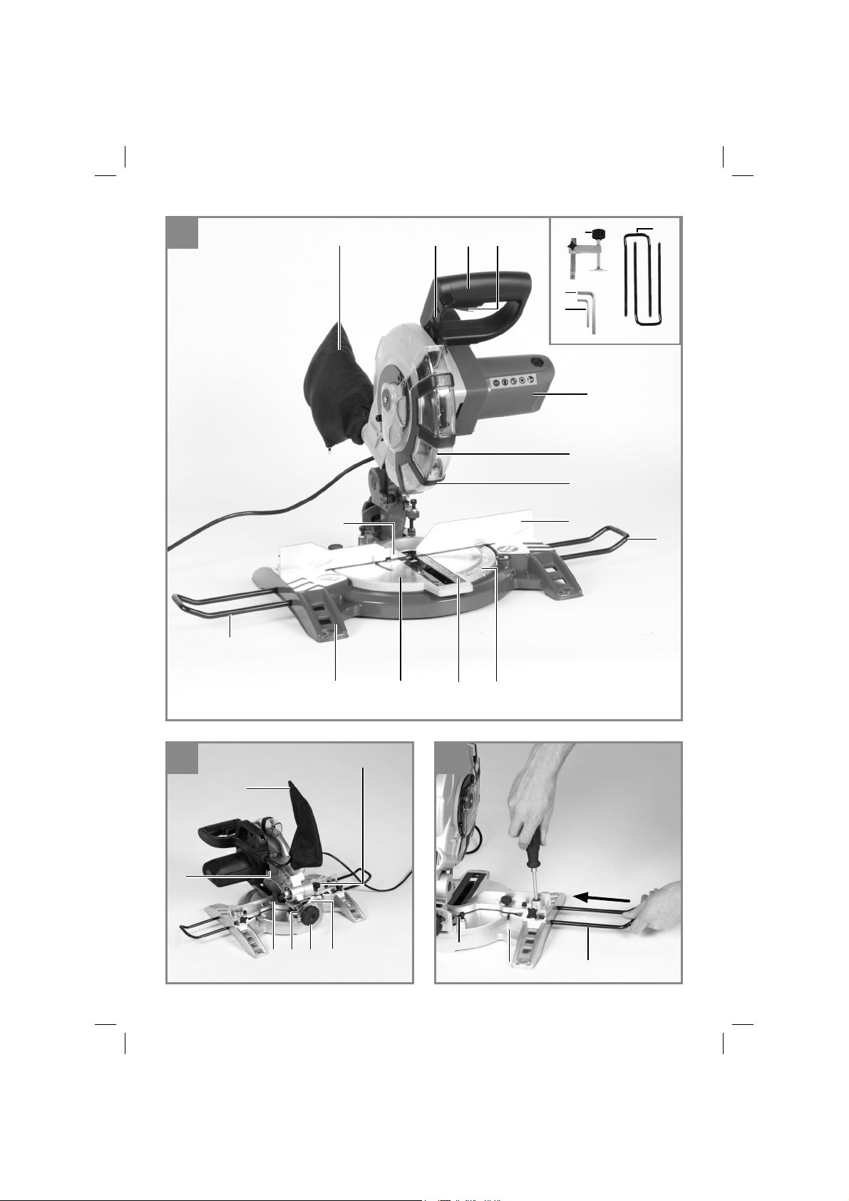
5.2 Säge aufbauen (Abb. 3)
Die Werkstückaufl agen müssen eingesteckt und
mit einem Kreuzschlitz-Schraubendreher festge-
zogen werden.
Schraubendreher nicht im Lieferumfang
enthalten
5.3 Säge einstellen. (Abb. 1/2)
•
Zum Verstellen des Drehtisches (8) die Rän-
delschraube (10) um ca. 2 Umdrehungen
lockern, um den Drehtisch zu entriegeln.
•
Der Drehtisch besitzt Raststellungen bei 0°,
5°, 10°, 15°, 22,5°, 30°, 35°, 40°, 45°. Sobald
der Drehtisch eingerastet ist, muss die Stel-
lung durch Festdrehen der Rändelschraube
(10) zusätzlich fixiert werden.
•
Sollten andere Winkelstellungen benötigt
werden, so wird der Drehteller (8) nur über
die Rändelschraube (10) fixiert.
•
Durch leichtes Drücken des Maschinenkop-
fes (4) nach unten und gleichzeitiges Heraus-
ziehen des Sicherungsbolzens (16) aus der
Motorhalterung, wird die Säge in der unteren
Arbeitsstellung entriegelt.
•
Maschinenkopf (4) nach oben schwenken.
•
Der Maschinenkopf (4) kann durch lösen der
Spannschraube (12) nach links auf max. 45°
geneigt werden.
Anl_TC_MS_2112_SPK1.indb 9Anl_TC_MS_2112_SPK1.indb 9 12.08.15 09:4612.08.15 09:46

D
- 10 -
•
Netzspannung mit Spannungsangabe auf
dem Datenschild auf Übereinstimmung prü-
fen und Gerät anstecken.
5.4 Feinjustierung der Anschlagsschiene
(Abb. 7/8)
•
Den Maschinenkopf (4) nach unten senken
und mit dem Sicherungsbolzen (16) fixie-
ren.
•
Den Drehtisch (8) auf 0° Stellung fixieren.
•
90°-Anschlagwinkel (a) zwischen Sägeblatt
(5) und Anschlagschiene (7) anlegen.
•
Justierschrauben (28) lockern, Anschlag-
schiene (7) auf 90° zum Sägeblatt (5) einstel-
len und Justierschrauben (28) wieder festzie-
hen.
5.5 Feinjustierung des Anschlags für Kapp-
schnitt 90° (Abb. 8-10)
•
Den Maschinenkopf (4) nach unten senken
und mit dem Sicherungsbolzen (16) fixieren.
•
Spannschraube (12) lockern.
•
Anschlagwinkel (a) zwischen Sägeblatt (5)
und Drehtisch (8) anlegen.
•
Gegenmutter (29) lockern und die Justier-
schraube (18) soweit verstellen, bis der Win-
kel zwischen Sägeblatt (5) und Drehtisch (8)
90° beträgt.
•
Um diese Einstellung zu fixieren Gegenmut-
ter (29) wieder festziehen.
•
Überprüfen Sie abschließend die Position der
Winkelanzeige (11). Falls erforderlich, Zeiger
mit Kreuzschlitzschraubendreher lösen, auf
0°-Position der Winkelskala (15) setzen und
Halteschraube wieder festziehen.
•
Anschlagwinkel nicht im Lieferumfang enthal-
ten.
5.6 Feinjustierung des Anschlags für Geh-
rungsschnitt 45° (Abb. 8/12)
•
Den Maschinenkopf (4) nach unten senken
und mit dem Sicherungsbolzen (16) fixieren.
•
Den Drehtisch (8) auf 0° Stellung fixieren.
•
Die Spannschraube (12) lösen und mit dem
Handgriff (2) den Maschinenkopf (4) nach
links, auf 45° neigen.
•
45°-Anschlagwinkel (b)zwischen Sägeblatt
(5) und Drehtisch (8) anlegen.
•
Gegenmutter (30) lockern und Justierschrau-
be (19) soweit verstellen, bis der Winkel zwi-
schen Sägeblatt (5) und Drehtisch (8) genau
45° beträgt.
•
Gegenmutter (30) wieder festziehen um die-
se Einstellung zu fixieren.
•
Anschlagwinkel nicht im Lieferumfang enthal-
ten.
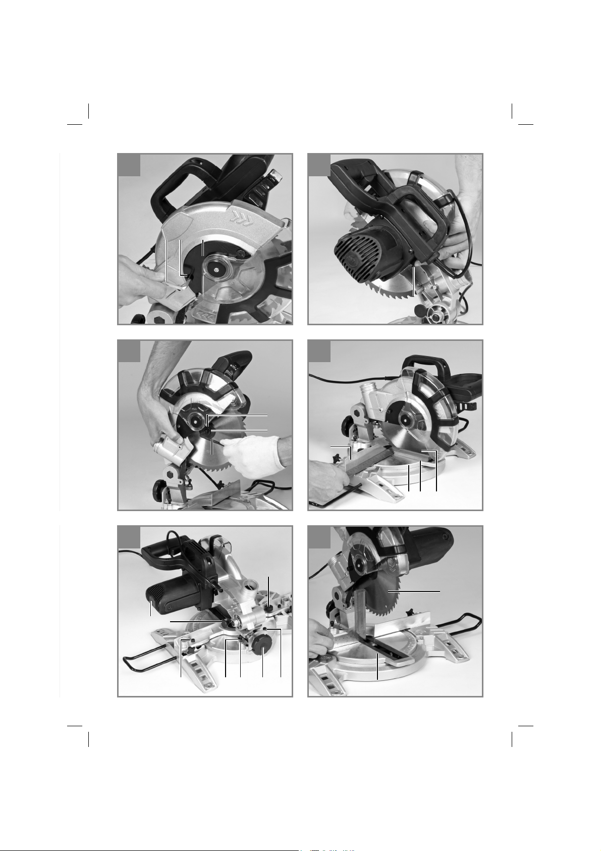
6. Betrieb
6.1 Kappschnitt 90° und Drehtisch 0° (Abb.1)
•
Die Säge wird durch Drücken des Haupt-
schalters (3) eingeschaltet.
•
Achtung! Das zu sägende Material fest auf
die Maschinenfläche auflegen, damit das
Material sich während des Schneidens nicht
verschiebt.
•
Nach dem Einschalten der Säge abwarten,
bis das Sägeblatt (5) seine maximale Dreh-
zahl erreicht hat.
•
Entriegelungshebel(1) seitlich drücken und
Maschinenkopf mit dem Griff (2) gleichmäßig
und mit leichtem Druck nach unten durch das
Werkstück bewegen.
•
Nach Beendigung des Sägevorgangs Ma-
schinenkopf wieder in die obere Ruhestellung
bringen und Ein,- Ausschalter (3) loslassen.
Achtung! Durch die Rückholfeder schlägt die
Maschine automatisch nach oben, d.h. Griff
(2) nach Schnittende nicht loslassen, sondern
Maschinenkopf langsam und unter leichtem
Gegendruck nach oben bewegen.
6.2 Kappschnitt 90° und Drehtisch 0°- 45°
(Abb. 10)
Mit der Kappsäge können Schrägschnitte nach
links und rechts von 0°-45° zur Anschlagschiene
ausgeführt werden.
•
Maschinenkopf (4) in die obere Stellung brin-
gen.
•
Den Drehtisch (8) durch Lockern des Fest-
stellgriffes (10) lösen.
•
Mit dem Handgriff (2) den Drehtisch (8) auf
den gewünschten Winkel einstellen, d.h. die
Markierung auf dem Drehtisch muß mit dem
gewünschtem Winkelmaß (17) auf der fest-
stehenden Bodenplatte (9) übereinstimmen.
•
Den Feststellgriff (10) wieder festziehen um
Drehtisch (8) zu fixieren.
•
Schnitt wie unter Punkt 6.1 beschrieben aus-
führen.
Anl_TC_MS_2112_SPK1.indb 10Anl_TC_MS_2112_SPK1.indb 10 12.08.15 09:4612.08.15 09:46

D
- 11 -
6.3 Gehrungsschnitt 0°- 45° und Drehtisch 0°
(Abb. 8/11)
Mit der Kappsäge können Gehrungsschnitte nach
links von 0°- 45° zur Arbeitsfl äche ausgeführt
werden.
•
Maschinenkopf (4) in die obere Stellung brin-
gen.
•
Den Drehtisch (8) auf 0° Stellung fixieren.
•
Die Spannschraube (12) lösen und mit dem
Handgriff (2) den Maschinenkopf (4) nach
links neigen, bis der Zeiger (11) auf das ge-
wünschte Winkelmaß (15) zeigt.
•
Feststellmutter (12) wieder festziehen und
Schnitt wie unter Punkt 6.1 beschrieben
durchführen.
6.4 Gehrungsschnitt 0°- 45° und Drehtisch
0°- 45° (Abb. 8/13)
Mit der Kappsäge können Gehrungsschnitte nach
links von 0°- 45° zur Arbeitsfl äche und gleich-
zeitig 0°- 45° zur Anschlagschiene ausgeführt
werden (Doppelgehrungsschnitt).
•
Maschinenkopf (4) in die obere Stellung brin-
gen.
•
Den Drehtisch (8) durch Lockern des Fest-
stellgriffes (10) lösen.
•
Mit dem Handgriff (2) den Drehtisch (8) auf
den gewünschten Winkel einstellen (siehe
hierzu auch Punkt 6.2.
•
Die Spannschraube (10) wieder festziehen
um Drehtisch zu fixieren.
•
Die Spannschraube (12) lösen und mit dem
Handgriff (2) den Maschinenkopf (4) nach
links, auf das gewünschte Winkelmaß neigen
(siehe hierzu auch Punkt 6.3.
•
Spannschraube (12) wieder festziehen.
•
Schnitt wie unter Punkt 6.1 beschrieben aus-
führen.
6.5 Spänefangsack (Abb. 2)
Die Säge ist mit einem Fangsack (14) für Späne
ausgestattet.
Der Spänesack (14) kann über den Reißver-
schluss auf der Unterseite entleert werden.
6.6 Austausch des Sägeblatts (Abb. 1-6)
•
Vor Austausch des Sägeblattes: Netzstecker
ziehen!
•
Tragen Sie beim Sägeblattwechsel Hand-
schuhe, um Verletzungen zu vermeiden!
•
Schwenken Sie den Maschinenkopf (4) nach
oben.
•
Öffnen Sie die Schraube (z) am Abdeckblech
(f) des Sägeblattes
•
Ziehen Sie den beweglichen Sägeblattschutz
(6) zurück und drehen Sie gleichzeitig das
Abdeckblech, so dass die Flanschschraube
zugänglich wird.
•
Drücken Sie mit einer Hand die Sägewellen-
sperre (13) und setzen Sie mit der anderen
Hand den Inbusschlüssel (d) auf die Flansch-
schraube (31). Nach max. einer Umdrehung
rastet die Sägewellensperre (13) ein.
•
Jetzt mit etwas mehr Kraftaufwand Flansch-
schraube (31) im Uhrzeigersinn lösen.
•
Drehen Sie die Flanschschraube (31) ganz
heraus und nehmen Sie den Außenflansch
(32) ab.
•
Das Sägeblatt (5) vom Innenflansch abneh-
men und nach unten herausziehen.
•
Flanschschraube (31), Außenflansch (32)
und Innenflansch sorgfältig reinigen.
•
Das neue Sägeblatt (5) in umgekehrter Rei-
henfolge wieder einsetzen und festziehen.
•
Achtung! Die Schnittschräge der Zähne d.h.
die Drehrichtung des Sägeblattes (5), muss
mit der Richtung des Pfeils auf dem Gehäuse
übereinstimmen.
•
Bevor Sie mit der Säge weiter arbeiten, ist die
Funktionsfähigkeit der Schutzeinrichtungen
zu prüfen.
•
Achtung! Nach jedem Sägeblattwechsel prü-
fen, ob das Sägeblatt in senkrechter Stellung
sowie auf 45° gekippt, frei in der Tischeinlage
(22) läuft.
•
Achtung! Das Wechseln und Ausrichten des
Sägeblattes (5) muss ordnungsgemäß aus-
geführt werden.
7. Austausch der
Netzanschlussleitung
Gefahr!
Wenn die Netzanschlussleitung dieses Gerätes
beschädigt wird, muss sie durch den Hersteller
oder seinen Kundendienst oder eine ähnlich qua-
lifi zierte Person ersetzt werden, um Gefährdun-
gen zu vermeiden.
Anl_TC_MS_2112_SPK1.indb 11Anl_TC_MS_2112_SPK1.indb 11 12.08.15 09:4612.08.15 09:46

D
- 12 -
8. Reinigung, Wartung und
Ersatzteilbestellung
Gefahr!
Ziehen Sie vor allen Reinigungsarbeiten den
Netzstecker.
8.1 Reinigung
•
Halten Sie Schutzvorrichtungen, Luftschlitze
und Motorengehäuse so staub- und schmutz-
frei wie möglich. Reiben Sie das Gerät mit
einem sauberen Tuch ab oder blasen Sie es
mit Druckluft bei niedrigem Druck aus.
•
Wir empfehlen, dass Sie das Gerät direkt
nach jeder Benutzung reinigen.
•
Reinigen Sie das Gerät regelmäßig mit einem
feuchten Tuch und etwas Schmierseife. Ver-
wenden Sie keine Reinigungs- oder Lösungs-
mittel; diese könnten die Kunststoffteile des
Gerätes angreifen. Achten Sie darauf, dass
kein Wasser in das Geräteinnere gelangen
kann. Das Eindringen von Wasser in ein Elek-
trogerät erhöht das Risiko eines elektrischen
Schlages.
8.2 Kohlebürsten
Bei übermäßiger Funkenbildung lassen Sie die
Kohlebürsten durch eine Elektrofachkraft über-
prüfen. Achtung! Die Kohlebürsten dürfen nur von
einer Elektrofachkraft ausgewechselt werden.
8.3 Wartung
•
Im Geräteinneren befinden sich keine weite-
ren zu wartenden Teile.
•
Alle beweglichen Teile sind in periodischen
Zeitabständen nachzuschmieren.
8.4 Ersatzteil- und Zubehörbestellung:
Bei der Ersatzteilbestellung sollten folgende An-
gaben gemacht werden;
•
Typ des Gerätes
•
Artikelnummer des Gerätes
•
Ident-Nummer des Gerätes
•
Ersatzteilnummer des erforderlichen Ersatz-
teils
Aktuelle Preise und Infos fi nden Sie unter
www.isc-gmbh.info
Tipp! Für ein gutes Arbeits-
ergebnis empfehlen wir
hochwertiges Zubehör von
! www.kwb.eu
welcome@kwb.eu
9. Entsorgung und
Wiederverwertung
Das Gerät befi ndet sich in einer Verpackung um
Transportschäden zu verhindern. Diese Verpa-
ckung ist Rohstoff und ist somit wieder verwend-
bar oder kann dem Rohstoff kreislauf zurückge-
führt werden. Das Gerät und dessen Zubehör
bestehen aus verschiedenen Materialien, wie
z.B. Metall und Kunststoff e. Defekte Geräte ge-
hören nicht in den Hausmüll. Zur fachgerechten
Entsorgung sollte das Gerät an einer geeigneten
Sammelstellen abgegeben werden. Wenn Ihnen
keine Sammelstelle bekannt ist, sollten Sie bei
der Gemeindeverwaltung nachfragen.
10. Lagerung
Lagern Sie das Gerät und dessen Zubehör an
einem dunklen, trockenen und frostfreiem sowie
für Kinder unzugänglichem Ort. Die optimale
Lagertemperatur liegt zwischen 5 und 30 ˚C.
Bewahren Sie das Elektrowerkzeug in der Origi-
nalverpackung auf.
Anl_TC_MS_2112_SPK1.indb 12Anl_TC_MS_2112_SPK1.indb 12 12.08.15 09:4612.08.15 09:46

D
- 13 -
Nur für EU-Länder
Werfen Sie Elektrowerkzeuge nicht in den Hausmüll!
Gemäß europäischer Richtlinie 2012/19/EG über Elektro- und Elektronik-Altgeräte und Umsetzung in
nationales Recht müssen verbrauchte Elektrowerkzeuge getrennt gesammelt werden und einer umwelt-
gerechten Wiederverwertung zugeführt werden.
Recycling-Alternative zur Rücksendeauff orderung:
Der Eigentümer des Elektrogerätes ist alternativ anstelle Rücksendung zur Mitwirkung bei der sachge-
rechten Verwertung im Falle der Eigentumsaufgabe verpfl ichtet. Das Altgerät kann hierfür auch einer
Rücknahmestelle überlassen werden, die eine Beseitigung im Sinne der nationalen Kreislaufwirt-
schafts- und Abfallgesetze durchführt. Nicht betroff en sind den Altgeräten beigefügte Zubehörteile und
Hilfsmittel ohne Elektrobestandteile.
Der Nachdruck oder sonstige Vervielfältigung von Dokumentation und Begleitpapieren der Produkte,
auch auszugsweise, ist nur mit ausdrücklicher Zustimmung der iSC GmbH zulässig.
Technische Änderungen vorbehalten
Anl_TC_MS_2112_SPK1.indb 13Anl_TC_MS_2112_SPK1.indb 13 12.08.15 09:4612.08.15 09:46

D
- 14 -
Service-Informationen
Wir unterhalten in allen Ländern, welche in der Garantieurkunde benannt sind, kompetente Service-
Partner, deren Kontakte Sie der Garantieurkunde entnehmen. Diese stehen Ihnen für alle Service-
Belange wie Reparatur, Ersatzteil- und Verschleißteil-Versorgung oder den Bezug von Verbrauchsmate-
rialien zur Verfügung.
Es ist zu beachten, dass bei diesem Produkt folgende Teile einem gebrauchsgemäßen oder natürlichen
Verschleiß unterliegen bzw. folgende Teile als Verbrauchsmaterialien benötigt werden.
Kategorie Beispiel
Verschleißteile* Kohlebürsten
Verbrauchsmaterial/ Verbrauchsteile* Sägeblatt
Fehlteile
* nicht zwingend im Lieferumfang enthalten!
Bei Mängel oder Fehlern bitten wir Sie, den Fehlerfall im Internet unter www.isc-gmbh.info anzumelden.
Bitte achten Sie auf eine genaue Fehlerbeschreibung und beantworten Sie dazu in jedem Fall folgende
Fragen:
•
Hat das Gerät bereits einmal funktioniert oder war es von Anfang an defekt?
•
Ist Ihnen vor dem Auftreten des Defektes etwas aufgefallen (Symptom vor Defekt)?
•
Welche Fehlfunktion weist das Gerät Ihrer Meinung nach auf (Hauptsymptom)?
Beschreiben Sie diese Fehlfunktion.
Anl_TC_MS_2112_SPK1.indb 14Anl_TC_MS_2112_SPK1.indb 14 12.08.15 09:4612.08.15 09:46

D
- 15 -
Garantieurkunde
Sehr geehrte Kundin, sehr geehrter Kunde,
unsere Produkte unterliegen einer strengen Qualitätskontrolle. Sollte dieses Gerät dennoch einmal nicht
einwandfrei funktionieren, bedauern wir dies sehr und bitten Sie, sich an unseren Servicedienst unter
der auf dieser Garantiekarte angegebenen Adresse zu wenden. Gerne stehen wir Ihnen auch telefo-
nisch über die angegebene Servicerufnummer zur Verfügung. Für die Geltendmachung von Garantiean-
sprüchen gilt folgendes:
1. Diese Garantiebedingungen regeln zusätzliche Garantieleistungen, die der u. g. Hersteller zusätz-
lich zur gesetzlichen Gewährleistung Käufern seiner Neugeräte verspricht. Ihre gesetzlichen Ge-
währleistungsansprüche werden von dieser Garantie nicht berührt. Unsere Garantieleistung ist für
Sie kostenlos.
2. Die Garantieleistung erstreckt sich ausschließlich auf Mängel an einem von Ihnen erworbenen neu-
en Gerät des u. g. Herstellers, die auf einem Material- oder Herstellungsfehler beruhen und ist nach
unserer Wahl auf die Behebung solcher Mängel am Gerät oder den Austausch des Gerätes be-
schränkt. Bitte beachten Sie, dass unsere Geräte bestimmungsgemäß nicht für den gewerblichen,
handwerklichen oder berufl ichen Einsatz konstruiert wurden. Ein Garantievertrag kommt daher nicht
zustande, wenn das Gerät innerhalb der Garantiezeit in Gewerbe-, Handwerks- oder Industriebe-
trieben verwendet wurde oder einer gleichzusetzenden Beanspruchung ausgesetzt war.
3. Von unserer Garantie ausgenommen sind:
- Schäden am Gerät, die durch Nichtbeachtung der Montageanleitung oder aufgrund nicht fach-
gerechter Installation, Nichtbeachtung der Gebrauchsanleitung (wie durch z.B. Anschluss an eine
falsche Netzspannung oder Stromart) oder Nichtbeachtung der Wartungs- und Sicherheitsbestim-
mungen oder durch Aussetzen des Geräts an anomale Umweltbedingungen oder durch mangelnde
Pfl ege und Wartung entstanden sind.
- Schäden am Gerät, die durch missbräuchliche oder unsachgemäße Anwendungen (wie z.B. Über-
lastung des Gerätes oder Verwendung von nicht zugelassenen Einsatzwerkzeugen oder Zubehör),
Eindringen von Fremdkörpern in das Gerät (wie z.B. Sand, Steine oder Staub, Transportschäden),
Gewaltanwendung oder Fremdeinwirkungen (wie z. B. Schäden durch Herunterfallen) entstanden
sind.
- Schäden am Gerät oder an Teilen des Geräts, die auf einen gebrauchsgemäßen, üblichen oder
sonstigen natürlichen Verschleiß zurückzuführen sind.
4. Die Garantiezeit beträgt 24 Monate und beginnt mit dem Kaufdatum des Gerätes. Garantieansprü-
che sind vor Ablauf der Garantiezeit innerhalb von zwei Wochen, nachdem Sie den Defekt erkannt
haben, geltend zu machen. Die Geltendmachung von Garantieansprüchen nach Ablauf der Ga-
rantiezeit ist ausgeschlossen. Die Reparatur oder der Austausch des Gerätes führt weder zu einer
Verlängerung der Garantiezeit noch wird eine neue Garantiezeit durch diese Leistung für das Gerät
oder für etwaige eingebaute Ersatzteile in Gang gesetzt. Dies gilt auch bei Einsatz eines Vor-Ort-
Services.
5. Für die Geltendmachung Ihres Garantieanspruches melden Sie bitte das defekte Gerät an unter:
www.isc-gmbh.info. Ist der Defekt des Gerätes von unserer Garantieleistung erfasst, erhalten Sie
umgehend ein repariertes oder neues Gerät zurück.
Selbstverständlich beheben wir gegen Erstattung der Kosten auch gerne Defekte am Gerät, die vom
Garantieumfang nicht oder nicht mehr erfasst sind. Dazu senden Sie das Gerät bitte an unsere Service-
adresse.
Für Verschleiß-, Verbrauchs- und Fehlteile verweisen wir auf die Einschränkungen dieser Garantie ge-
mäß den Service-Informationen dieser Bedienungsanleitung.
iSC GmbH · Eschenstraße 6 · 94405 Landau/Isar (Deutschland)
Anl_TC_MS_2112_SPK1.indb 15Anl_TC_MS_2112_SPK1.indb 15 12.08.15 09:4612.08.15 09:46

D
- 16 -
Sehr geehrte Kundin, sehr geehrter Kunde,
um Ihnen noch mehr Service zu bieten, haben Sie die Möglichkeit auf unserem Onlineportal weitere
Informationen abzurufen.
Sollten einmal Probleme oder Fragen zu Ihrem Produkt auftreten, können Sie schnell und einfach unter
www.isc-gmbh.info viele Aktionen durchführen. Hier einige Beispiele:
•
Ersatzteile bestellen
•
Aktuelle Preisauskünfte
•
Verfügbarkeiten der Ersatzteile
•
Servicestellen Vorort für Benzingeräte
•
Defekte Geräte anmelden
•
Garantieverlängerungen (nur bei bestimmten Geräten)
•
Bestellverfolgung
Wir freuen uns auf Ihren Besuch online unter www.isc-gmbh.info!
Telefon: 09951 / 95 920 00 ·Telefax: 09951/95 917 00
E-Mail: [email protected] · Internet: www.isc-gmbh.info
iSC GmbH · Eschenstraße 6 · 94405 Landau/Isar (Deutschland)
Anl_TC_MS_2112_SPK1.indb 16Anl_TC_MS_2112_SPK1.indb 16 12.08.15 09:4612.08.15 09:46

GB
- 17 -
Table of contents
1. Safety regulations
2. Layout and items supplied
3. Proper use
4. Technical data
5. Before starting the equipment
6. Operation
7. Replacing the power cable
8. Cleaning, maintenance and ordering of spare parts
9. Disposal and recycling
10. Storage
Anl_TC_MS_2112_SPK1.indb 17Anl_TC_MS_2112_SPK1.indb 17 12.08.15 09:4612.08.15 09:46

GB
- 18 -
Caution! Risk of injury! Do not reach into the running saw blade.
Danger! - Read the operating instructions to reduce the risk of injury
Caution! Wear ear-muff s. The impact of noise can cause damage to hearing.
Caution! Wear safety goggles. Sparks generated during working or splinters, chips and dust emitted
by the device can cause loss of sight.
Caution! Wear a breathing mask. Dust which is injurious to health can be generated when working on
wood and other materials. Never use the device to work on any materials containing asbestos!
Anl_TC_MS_2112_SPK1.indb 18Anl_TC_MS_2112_SPK1.indb 18 12.08.15 09:4612.08.15 09:46

GB
- 19 -
Danger!
When using the equipment, a few safety pre-
cautions must be observed to avoid injuries and
damage. Please read the complete operating
instructions and safety regulations with due care.
Keep this manual in a safe place, so that the in-
formation is available at all times. If you give the
equipment to any other person, hand over these
operating instructions and safety regulations as
well. We cannot accept any liability for damage
or accidents which arise due to a failure to follow
these instructions and the safety instructions.
1. Safety regulations
The corresponding safety information can be
found in the enclosed booklet.
Danger!
Read all safety regulations and instructions.
Any errors made in following the safety regula-
tions and instructions may result in an electric
shock, fi re and/or serious injury.
Keep all safety regulations and instructions
in a safe place for future use.
2. Layout and items supplied
2.1 Layout (Fig. 1/2)
1. Release lever
2. Handle
3. ON/OFF switch
4. Machine head
5. Saw blade
6. Movable blade guard
7. Stop rail
8. Turntable
9. Stationary base plate
10. Knurled screw
11. Pointer
12. Tightening screw
13. Saw shaft lockt
14. Debris bag
15. Scale
16. Safety pin
17. Scale (turntable)
18. Setting screw 0°
19. Setting screw 45°
20. Workpiece support
21. Clamping device
22. Table insert
23. Movable stop, dependent on table angle
2.2 Items supplied
Please check that the article is complete as
specifi ed in the scope of delivery. If parts are
missing, please contact our service center or the
sales outlet where you made your purchase at
the latest within 5 working days after purchasing
the product and upon presentation of a valid bill
of purchase. Also, refer to the warranty table in
the service information at the end of the operating
instructions.
•
Open the packaging and take out the equip-
ment with care.
•
Remove the packaging material and any
packaging and/or transportation braces (if
available).
•
Check to see if all items are supplied.
•
Inspect the equipment and accessories for
transport damage.
•
If possible, please keep the packaging until
the end of the guarantee period.
Danger!
The equipment and packaging material are
not toys. Do not let children play with plastic
bags, foils or small parts. There is a danger of
swallowing or suff ocating!
•
Crosscut and miter saw
•
Carbide-tipped saw blade
•
Allen key (c,d)
•
Sawdust bag (14)
•
Workpiece support (20)
•
Clamping device (21)
•
Original operating instructions
•
Safety instructions
Anl_TC_MS_2112_SPK1.indb 19Anl_TC_MS_2112_SPK1.indb 19 12.08.15 09:4612.08.15 09:46

GB
- 20 -
3. Proper use
The crosscut and miter saw is designed for cross-
cutting wood and wood-type materials which are
appropriate for the machine’s size. The saw is not
designed for cutting fi rewood.
The equipment is to be used only for its prescri-
bed purpose. Any other use is deemed to be a
case of misuse. The user / operator and not the
manufacturer will be liable for any damage or inju-
ries of any kind caused as a result of this.
Please note that our equipment has not been de-
signed for use in commercial, trade or industrial
applications. Our warranty will be voided if the
machine is used in commercial, trade or industrial
businesses or for equivalent purposes.
The equipment is to be operated only with suita-
ble saw blades. It is prohibited to use any type of
cutting-off wheel.
To use the equipment properly you must also
observe the safety information, the assembly
instructions and the operating instructions to be
found in this manual.
All persons who use and service the equipment
have to be acquainted with these operating
instructions and must be informed about the
equipment’s potential hazards. It is also imperati-
ve to observe the accident prevention regulations
in force in your area. The same applies for the
general rules of health and safety at work.
The manufacturer will not be liable for any chan-
ges made to the equipment nor for any damage
resulting from such changes. Even when the
equipment is used as prescribed it is still impos-
sible to eliminate certain residual risk factors. The
following hazards may arise in connection with
the machine’s construction and design:
•
Contact with the saw blade in the uncovered
saw zone.
•
Reaching into the running saw blade (cut inju-
ries).
•
Kick-back of workpieces and parts of workpi-
eces.
•
Saw blade fracturing.
•
Catapulting of faulty carbide tips from the saw
blade.
•
Damage to hearing if ear-muffs are not used
as necessary.
•
Harmful emissions of wood dust when used
in closed rooms.
4. Technical data
Asynchronous motor ...................... 230 V ~ 50 Hz
Input power .... S1 1400 Watt / S6 40% 1600 Watt
Idle speed n
0
......................................... 5000 rpm
Carbide saw blade .............. ø210 x ø30 x 2,8 mm
Number of teeth ............................................... 48
Weight.........................................................7,1 kg
Tilting range .................................. -45° / 0° / +45°
Mitre cuts ................................ 0° to 45° to the left
Sawing width at 90° ................ max. 120 x 55 mm
Sawing width at 45° .................. max. 80 x 55 mm
Sawing width at 2 x 45°
(double mitre cuts) .............................80 x 32 mm
Minimum workpiece size: Only ever cut workpie-
ces which are big enough to clamp securely with
the clamping device – minimum length 160 mm.
Operating mode S6 40%: Continuous operation
with idling (cycle time 10 minutes). To ensure that
the motor does not become excessively hot it
may only be operated for 40% of the cycle at the
specifi ed rating and must then be allowed to idle
for 60% of the cycle.
Danger!
Sound and vibration
Sound and vibration values were measured in
accordance with EN 61029.
L
pA
sound pressure level ..................... 88.7 dB(A)
K
pA
uncertainty ............................................. 3 dB
L
WA
sound power level ..................... 101.7 dB(A)
K
WA
uncertainty .............................................3 dB
Wear ear-muff s.
The impact of noise can cause damage to hea-
ring.
Total vibration values (vector sum of three direc-
tions) determined in accordance with EN 61029.
Vibration emission value a
h
= 2.70 m/s
2
K uncertainty = 1.5 m/s
2
Anl_TC_MS_2112_SPK1.indb 20Anl_TC_MS_2112_SPK1.indb 20 12.08.15 09:4612.08.15 09:46

GB
- 21 -
The specifi ed vibration value was established in
accordance with a standardized testing method. It
may change according to how the electric equip-
ment is used and may exceed the specifi ed value
in exceptional circumstances.
The specifi ed vibration value can be used to
compare the equipment with other electric power
tools.
The specifi ed vibration value can be used for initi-
al assessment of a harmful eff ect.
Keep the noise emissions and vibrations to a
minimum.
•
Only use appliances which are in perfect wor-
king order.
•
Service and clean the appliance regularly.
•
Adapt your working style to suit the appliance.
•
Do not overload the appliance.
•
Have the appliance serviced whenever ne-
cessary.
•
Switch the appliance off when it is not in use.
Caution!
Residual risks
Even if you use this electric power tool in
accordance with instructions, certain resi-
dual risks cannot be rules out. The following
hazards may arise in connection with the
equipment’s construction and layout:
1. Lung damage if no suitable protective dust
mask is used.
2. Damage to hearing if no suitable ear protec-
tion is used.
3. Health damage caused by hand-arm vib-
rations if the equipment is used over a pro-
longed period or is not properly guided and
maintained.
5. Before starting the equipment
Before you connect the equipment to the mains
supply make sure that the data on the rating plate
are identical to the mains data.
Warning!
Always pull the power plug before making
adjustments to the equipment.
5.1 General information
•
The equipment must be set up where it can
stand securely, i.e. it should be bolted to a
workbench, a universal base frame or similar.
•
All covers and safety devices have to be pro-
perly fitted before the equipment is switched
on.
•
It must be possible for the blade to run freely.
•
When working with wood that has been pro-
cessed before, watch out for foreign bodies
such as nails or screws, etc.
•
Before you actuate the On/Off switch, make
sure that the saw blade is correctly fitted
and that the equipment’s moving parts run
smoothly.
5.2 Setting up the saw (Fig. 3)
The workpiece supports must be inserted and
tightened using a Phillips screwdriver.
Screwdriver not included in delivery.
5.3 Adjusting the saw (Fig. 1/2)
•
To adjust the turntable (8), loosen the knurled
screw (10) by approx. 2 turns, which frees the
turntable.
•
The turntable has locking points at angles
of 0°, 5°, 10°, 15°, 22,5°, 30°, 35°, 40°, 45°.
Once the turntable is engaged, the setting
must be additionally secured by tightening
the knurled screw (10).
•
If different angle settings are required, the
turntable (8) may be secured in position using
only the knurled screw (10).
•
Lightly press the machine head (4) down
while at the same time pulling the retaining
pin (16) out from the motor mounting; this
causes the saw to move down to the lower
working position.
•
Swing up the machine head (4).
•
By loosening the lock screw (12), the machi-
ne head (4) can be angled to the left up to
45°.
•
Check that the voltage marked on the rating
plate is the same as your mains voltage and
connect up the machine.
Anl_TC_MS_2112_SPK1.indb 21Anl_TC_MS_2112_SPK1.indb 21 12.08.15 09:4612.08.15 09:46

GB
- 22 -
5.4 Precision adjustment of the stop rail
(Fig. 7/8)
•
Lower the machine head (4) and fasten in
place with the safety pin (16).
•
Fasten the turntable (8) in 0° position.
•
Place the 90° stop angle (a) between the bla-
de (5) and the stop rail (7).
•
Slacken the adjustment screws (28), set the
stop rail (7) to 90° in relation to the saw blade
(5) and retighten the adjustment screws (28).
5.5 Precision adjustment of the stop for 90°
cross-cuts (Fig. 8-10)
•
Lower the machine head (4) and fix with the
lock pin (16).
•
Slacken the tightening screw (12).
•
Place the stop angle (a) between the saw
blade (5) and the rotary table (8).
•
Slacken the counter nut (29) and adjust the
setting screw (18) until the angle between the
saw blade (5) and the rotary table (8) equals
90°.
•
Re-tighten the counter nut (29) to fix the ma-
chine in this setting.
•
Finally, check the position of the angle indica-
tor (11). If necessary, release the pointer with
a crosstip screwdriver, move to the 0° position
of the angle scale (15) and retighten the hol-
ding screw.
•
No stop angle included.
5.6 Precision adjustment of the stop for 45°
mitre cuts (Fig. 8/12)
•
Lower the machine head (4) and fix with the
lock pin (16).
•
Fix the rotary table (8) in 0° position.
•
Undo the tightening screw (12) and use the
handle (2) to tilt the machine head (4) to the
left until it coincides at 45°.
•
Place the 45° stop angle (b) between the saw
blade (5) and the rotary table (8).
•
Slacken the counter nut (30) and adjust the
setting screw (19) until the angle between the
saw (5) and the rotary table (8) equals exactly
45°.
•
No stop angle included.
6. Operation
6.1 Crosscut 90° and turntable 0° (Fig. 1)
•
Press the main switch (3) to turn on the saw.
•
Important. Place the material for sawing firmly
on the machine surface, to prevent it from
moving during the sawing process.
•
After switching on the saw, wait for the blade
(5) to reach its maximum speed.
•
Press the release lever (1) sideways and,
using the handle (2), apply steady and light
downward pressure to move the machine
head through the workpiece.
•
When the cut is completed, return the machi-
ne to its top parking position and let go of the
On/Off switch.
•
Caution! A return spring causes the machine
head to rise automatically at the end of the
cut. Do not let go of the handle (2) as soon as
the cut is completed but steady the machine
head and allow it to rise slowly.
6.2 90° cross-cuts and 0°-45° rotary table
(Fig. 10)
The crosscut saw can be used to make right and
left angular cuts of 0°- 45° in relation to the stop
rail.
•
Lift the machine head (4) to its top position.
•
Release the turntable (8) by slackening the
locking grip (10).
•
Using the handle (2), set the turntable (8) to
the desired angle, i.e. the marking on the turn-
table must coincide with the desired angular
setting (17) on the stationary base plate (9).
•
Re-tighten the locking handle (10) in order to
fix the rotary table (8) in position.
•
Make the cut as described in Section 6.1).
6.3 Mitre cuts 0°-45° and rotary table 0°
(Fig. 8/11)
The crosscut saw can be used to make miter cuts
of 0° - 45° in relation to the work face.
•
Lift the machine head (4) to its top position.
•
Fix the rotary table (8) in 0° position.
•
Undo the tightening screw (12) and use the
handle (2) to tilt the machine head (4) to the
left until the pointer (11) coincides with the
required angle value (15).
•
Re-tighten the locking nut (12) and make the
cut as described in Section 6.1).
Anl_TC_MS_2112_SPK1.indb 22Anl_TC_MS_2112_SPK1.indb 22 12.08.15 09:4612.08.15 09:46

GB
- 23 -
6.4 Mitre cuts 0°-45° and rotary table 0°-45°
(Fig. 8/13)
The crosscut saw can be used to make miter cuts
to the left of 0°- 45° in relation to the work face
and, at the same time, 0° - 45° in relation to the
stop rail (double miter cut).
•
Lift the machine head (4) to its top position.
•
Release the turntable (8) by slackening the
locking grip (10).
•
Adjust the rotary table (8) by its handle (2) to
the required angle (see also Section 6.2).
•
Retighten the tightening screw (10) in order to
secure the turntable in place.
•
Undo the tightening screw (12) and use the
handle (2) to tilt the machine head (4) to the
left until it coincides with the required angle
value (in this connection see also section
6.3).
•
Screw the tightening screw (12) back down
again.
6.5 Sawdust bag (Fig. 2)
The saw is equipped with a debris bag (14) for
sawdust and chips.
The debris bag (14) can be emptied by means of
a zipper at the bottom.
6.6 Replacing the saw blade (Fig. 1-6)
•
Before changing the saw blade: Remove the
power plug!
•
Wear work gloves to prevent injury when
changing the saw blade.
•
Swing the machine head upwards (4).
•
Undo the screw (z) on the cover plate (f) of
the saw blade.
•
Pull back the adjustable blade guard (6) and
at the same time turn the cover plate to achie-
ve access to the flange bolt.
•
Press the saw shaft lock (13) with one hand
while positioning the Allen key (d) on the
flange bolt (31) with the other hand. The saw
shaft lock (13) engages after no more than
one rotation.
•
Now, using a little more force, slacken the
flange screw (31) in the clockwise direction.
•
Turn the flange screw (31) right out and remo-
ve the external flange (32).
•
Take the blade (5) off the inner flange and pull
out downwards.
•
Carefully clean the flange screw (31), outer
flange (32) and inner flange.
•
Fit and fasten the new saw blade (5) in rever-
se order.
•
Important. The cutting angle of the teeth, in
other words the direction of rotation of the
saw blade (5) must coincide with the direction
of the arrow on the housing.
•
Check to make sure that all safety devices
are properly mounted and in good working
condition before you begin working with the
saw again.
•
Important. Every time that you change the
saw blade, check to see that it spins freely in
the table insert (22) in both perpendicular and
45° angle settings.
•
Important. The work to change and align the
saw blade (5) must be carried out correctly.
7. Replacing the power cable
Danger!
If the power cable for this equipment is damaged,
it must be replaced by the manufacturer or its
after-sales service or similarly trained personnel
to avoid danger.
8. Cleaning, maintenance and
ordering of spare parts
Danger!
Always pull out the mains power plug before star-
ting any cleaning work.
8.1 Cleaning
•
Keep all safety devices, air vents and the
motor housing free of dirt and dust as far as
possible. Wipe the equipment with a clean
cloth or blow it with compressed air at low
pressure.
•
We recommend that you clean the device
immediately each time you have finished
using it.
•
Clean the equipment regularly with a moist
cloth and some soft soap. Do not use
cleaning agents or solvents; these could at-
tack the plastic parts of the equipment. Ensu-
re that no water can seep into the device. The
ingress of water into an electric tool increases
the risk of an electric shock.
8.2 Carbon brushes
In case of excessive sparking, have the carbon
brushes checked only by a qualifi ed electrician.
Important! The carbon brushes should not be re-
placed by anyone but a qualifi ed electrician.
Anl_TC_MS_2112_SPK1.indb 23Anl_TC_MS_2112_SPK1.indb 23 12.08.15 09:4612.08.15 09:46
GB
- 24 -
8.3 Maintenance
•
There are no parts inside the equipment
which require additional maintenance.
•
Lubricate all moving parts at regular intervals.
8.4 Ordering spare parts and accessories
Please provide the following information when
ordering spare parts:
•
Type of unit
•
Article number of the unit
•
ID number of the unit
•
Spare part number of the required spare part
For our latest prices and information please go to
www.isc-gmbh.info
Tip! For good results we
recommend high-quality ac-
cessories from !
www.kwb.eu
welcome@kwb.eu
9. Disposal and recycling
The equipment is supplied in packaging to pre-
vent it from being damaged in transit. The raw
materials in this packaging can be reused or
recycled. The equipment and its accessories are
made of various types of material, such as metal
and plastic. Never place defective equipment in
your household refuse. The equipment should
be taken to a suitable collection center for proper
disposal. If you do not know the whereabouts of
such a collection point, you should ask in your
local council offi ces.
10. Storage
Store the equipment and accessories out of
children’s reach in a dark and dry place at above
freezing temperature. The ideal storage tempe-
rature is between 5 and 30 °C. Store the electric
tool in its original packaging.
Anl_TC_MS_2112_SPK1.indb 24Anl_TC_MS_2112_SPK1.indb 24 12.08.15 09:4612.08.15 09:46

GB
- 25 -
For EU countries only
Never place any electric power tools in your household refuse.
To comply with European Directive 2012/19/EC concerning old electric and electronic equipment and
its implementation in national laws, old electric power tools have to be separated from other waste and
disposed of in an environment-friendly fashion, e.g. by taking to a recycling depot.
Recycling alternative to the return request:
As an alternative to returning the equipment to the manufacturer, the owner of the electrical equipment
must make sure that the equipment is properly disposed of if he no longer wants to keep the equipment.
The old equipment can be returned to a suitable collection point that will dispose of the equipment in
accordance with the national recycling and waste disposal regulations. This does not apply to any ac-
cessories or aids without electrical components supplied with the old equipment.
The reprinting or reproduction by any other means, in whole or in part, of documentation and papers
accompanying products is permitted only with the express consent of the iSC GmbH.
Subject to technical changes
Anl_TC_MS_2112_SPK1.indb 25Anl_TC_MS_2112_SPK1.indb 25 12.08.15 09:4612.08.15 09:46

GB
- 26 -
Service information
We have competent service partners in all countries named on the guarantee certifi cate whose contact
details can also be found on the guarantee certifi cate. These partners will help you with all service re-
quests such as repairs, spare and wearing part orders or the purchase of consumables.
Please note that the following parts of this product are subject to normal or natural wear and that the
following parts are therefore also required for use as consumables.
Category Example
Wear parts* Carbon brushes
Consumables* Saw blade
Missing parts
* Not necessarily included in the scope of delivery!
In the eff ect of defects or faults, please register the problem on the internet at www.isc-gmbh.info. Ple-
ase ensure that you provide a precise description of the problem and answer the following questions in
all cases:
•
Did the equipment work at all or was it defective from the beginning?
•
Did you notice anything (symptom or defect) prior to the failure?
•
What malfunction does the equipment have in your opinion (main symptom)?
Describe this malfunction.
Anl_TC_MS_2112_SPK1.indb 26Anl_TC_MS_2112_SPK1.indb 26 12.08.15 09:4612.08.15 09:46

GB
- 27 -
Warranty certifi cate
Dear Customer,
All of our products undergo strict quality checks to ensure that they reach you in perfect condition. In the
unlikely event that your device develops a fault, please contact our service department at the address
shown on this guarantee card. You can also contact us by telephone using the service number shown.
Please note the following terms under which guarantee claims can be made:
1. These warranty terms regulate additional warranty services, which the manufacturer mentioned
below promises to buyers of its new products in addition to their statutory rights of guarantee. Your
statutory guarantee claims are not aff ected by this guarantee. Our guarantee is free of charge to
you.
2. The warranty services cover only defects due to material or manufacturing faults on a product which
you have bought from the manufacturer mentioned below and are limited to either the rectifi cation of
said defects on the product or the replacement of the product, whichever we prefer.
Please note that our devices are not designed for use in commercial, trade or professional applica-
tions. A guarantee contract will not be created if the device has been used by commercial, trade or
industrial business or has been exposed to similar stresses during the guarantee period.
3. The following are not covered by our guarantee:
- Damage to the device caused by a failure to follow the assembly instructions or due to incorrect
installation, a failure to follow the operating instructions (for example connecting it to an incorrect
mains voltage or current type) or a failure to follow the maintenance and safety instructions or by ex-
posing the device to abnormal environmental conditions or by lack of care and maintenance.
- Damage to the device caused by abuse or incorrect use (for example overloading the device or the
use or unapproved tools or accessories), ingress of foreign bodies into the device (such as sand,
stones or dust, transport damage), the use of force or damage caused by external forces (for ex-
ample by dropping it).
- Damage to the device or parts of the device caused by normal or natural wear or tear or by normal
use of the device.
4. The guarantee is valid for a period of 24 months starting from the purchase date of the device. Gu-
arantee claims should be submitted before the end of the guarantee period within two weeks of the
defect being noticed. No guarantee claims will be accepted after the end of the guarantee period.
The original guarantee period remains applicable to the device even if repairs are carried out or
parts are replaced. In such cases, the work performed or parts fi tted will not result in an extension
of the guarantee period, and no new guarantee will become active for the work performed or parts
fi tted. This also applies if an on-site service is used.
5. Please report the defective device on the following internet address to register your guarantee claim:
www.isc-gmbh.info. If the defect is covered by our guarantee, then the item in question will either be
repaired immediately and returned to you or we will send you a new replacement device.
Of course, we are also happy off er a chargeable repair service for any defects which are not covered by
the scope of this guarantee or for units which are no longer covered. To take advantage of this service,
please send the device to our service address.
Also refer to the restrictions of this warranty concerning wear parts, consumables and missing parts as
set out in the service information in these operating instructions.
Anl_TC_MS_2112_SPK1.indb 27Anl_TC_MS_2112_SPK1.indb 27 12.08.15 09:4612.08.15 09:46

F
- 28 -
Sommaire
1. Consignes de sécurité
2. Description de l’appareil et volume de livraison
3. Utilisation conforme à l’aff ectation
4. Données techniques
5. Avant la mise en service
6. Fonctionnement
7. Remplacement de la ligne de raccordement réseau
8. Nettoyage, maintenance et commande de pièces de rechange
9. Mise au rebut et recyclage
10. Stockage
Anl_TC_MS_2112_SPK1.indb 28Anl_TC_MS_2112_SPK1.indb 28 12.08.15 09:4612.08.15 09:46

F
- 29 -
Attention ! Risque de blessure ! Ne mettez pas vos doigts dans la lame en rotation.
Danger! - Lisez ce mode d’emploi pour diminuer le risque de blessures
Prudence! Portez une protection de l’ouïe. L’exposition au bruit peut entraîner une perte de l’ouïe.
Prudence! Portez des lunettes de protection. Les étincelles générées pendant travail ou les éclats,
copeaux et la poussière sortant de l’appareil peuvent entraîner une perte de la vue.
Prudence! Portez un masque anti-poussière. Lors de travaux sur su bois et autres matériaux, de
la poussière nuisible à la santé peut être dégagée. Ne travaillez pas sur du matériau contenant de
l’amiante !
Anl_TC_MS_2112_SPK1.indb 29Anl_TC_MS_2112_SPK1.indb 29 12.08.15 09:4612.08.15 09:46

F
- 30 -
Danger !
Lors de l’utilisation d’appareils, il faut respecter
certaines mesures de sécurité afi n d’éviter des
blessures et dommages. Veuillez donc lire atten-
tivement ce mode d’emploi/ces consignes de
sécurité. Veillez à le conserver en bon état pour
pouvoir accéder aux informations à tout moment.
Si l’appareil doit être remis à d’autres personnes,
veillez à leur remettre aussi ce mode d’emploi/
ces consignes de sécurité. Nous déclinons toute
responsabilité pour les accidents et dommages
dus au non-respect de ce mode d’emploi et des
consignes de sécurité.
1. Consignes de sécurité
Vous trouverez les consignes de sécurité corres-
pondantes dans le cahier en annexe.
Danger !
Veuillez lire toutes les consignes de sécurité
et instructions. Tout non-respect des consignes
de sécurité et instructions peut provoquer une
décharge électrique, un incendie et/ou des bles-
sures graves.
Conservez toutes les consignes de sécurité
et instructions pour une consultation ultéri-
eure.
2. Description de l’appareil et
volume de livraison
2.1 Description de l’appareil (fi gure 1/2)
1. Levier de déverrouillage
2. Poignée
3. Interrupteur Marche/Arrêt
4. Tête de la machine
5. Lame de scie
6. Capot de protection de lame de scie amovib-
le
7. Rail de butée
8. Table tournante
9. Plaque de sol fi xe
10. Vis moletée
11. Pointeur
12. Vis de serrage
13. Blocage de l’arbre de scie
14. Sac pour chutes
15. Graduation
16. Boulons de sécurité
17. Graduation (table tournante)
18. Vis de réglage 0°
19. Vis de réglage 45°
20. Support de pièce à usiner
21. Dispositif tendeur
22. Insertion de table
23. Butée mobile, en fonction de l‘angle du pla-
teau
2.2 Volume de livraison
Veuillez contrôler si l‘article est complet à l‘aide
de la description du volume de livraison. S‘il
manque des pièces, adressez-vous dans un délai
de 5 jours maximum après votre achat à notre
service après-vente ou au magasin où vous avez
acheté l‘appareil muni d‘une preuve d‘achat vala-
ble. Veuillez consulter pour cela le tableau des
garanties dans les informations service après-
vente à la fi n du mode d‘emploi.
•
Ouvrez l’emballage et prenez l’appareil en le
sortant avec précaution de l’emballage.
•
Retirez le matériel d’emballage tout comme
les sécurités d’emballage et de transport (s’il
y en a).
•
Vérifiez si la livraison est bien complète.
•
Contrôlez si l’appareil et ses accessoires ne
sont pas endommagés par le transport.
•
Conservez l’emballage autant que possible
jusqu’à la fin de la période de garantie.
Danger !
L’appareil et le matériel d’emballage ne sont
pas des jouets ! Il est interdit de laisser des
enfants jouer avec des sacs et des fi lms en
plastique et avec des pièces de petite taille.
Ils risquent de les avaler et de s’étouff er !
•
Scie à onglet radiale
•
Lame de scie à garnissage en métal dur
•
Clé à six pans creux (c, d)
•
Sac collecteur de copeaux (14)
•
Support de pièce à usiner(20)
•
Dispositif tendeur (21)
•
Mode d’emploi d’origine
•
Consignes de sécurité
Anl_TC_MS_2112_SPK1.indb 30Anl_TC_MS_2112_SPK1.indb 30 12.08.15 09:4612.08.15 09:46

F
- 31 -
3. Utilisation conforme à
l’aff ectation
La scie à onglet radiale sert au découpage de
bois et de matériaux semblables au bois selon la
taille de la machine. La scie ne convient pas pour
le découpage de bois de chauff age.
La machine doit exclusivement être employée
conformément à son aff ectation. Chaque uti-
lisation allant au-delà de cette aff ectation est
considérée comme non conforme. Pour les
dommages en résultant ou les blessures de tout
genre, le producteur décline toute responsabilité
et l’opérateur/l’exploitant est responsable.
Veillez au fait que nos appareils, conformément
à leur aff ectation, n’ont pas été construits, pour
être utilisés dans un environnement profession-
nel, industriel ou artisanal. Nous déclinons toute
responsabilité si l’appareil est utilisé profession-
nellement, artisanalement ou dans des sociétés
industrielles, tout comme pour toute activité
équivalente.
Seules les lames de scie correspondant au
modèle de la machine doivent être utilisées.
L’utilisation de meules tronçonneuses quel qu’en
soit le modèle est interdite.
Le respect des consignes de sécurité, du mode
d’emploi et des remarques de service dans le
mode d’emploi est aussi partie intégrante de
l’utilisation conforme à l’aff ectation.
Les personnes commandant la machine et en
eff ectuant la maintenance doivent la connaître et
avoir été instruites sur les diff érents risques pos-
sibles en découlant. En outre, il faut strictement
respecter les règlements de prévoyance contre
les accidents. Il faut respecter toutes les autres
règles des domaines de la médecine du travail et
de la technique de sécurité.
Toute modifi cation de la machine entraîne
l’annulation de la responsabilité du producteur, de
même pour les dommages en découlant. Malgré
l’emploi conforme à l’aff ectation, certains facteurs
de risque résiduels ne peuvent être complète-
ment supprimés. En raison de la construction et
de la conception de la machine, les risques su-
ivants peuvent apparaître :
•
Contact avec la lame de scie dans la zone de
la scie n’étant pas recouverte.
•
Toucher la lame de scie en fonctionnement
(blessure coupante).
•
Retour de pièces à usiner et de parties de
celles-ci.
•
Ruptures de lame de scie.
•
Expulsion de pièces de métal dures défectu-
euses de la lame de scie.
•
Troubles de l’ouïe si vous n’employez pas la
protection des oreilles nécessaire.
•
Émissions nocives de poussière de bois en
cas d’emploi de la scie dans des pièces fer-
mées.
4. Données techniques
Moteur à courant alternatif ............. 230 V ~ 50 Hz
Puissance absorbée ............................................
........................S1 1400 Watt / S6 40% 1600 Watt
Vitesse de rotation à vide n
0
.................5000 min
-1
Lame de scie en métal dur .ø 210 x ø 30 x 2,8 mm
Nombre de dents ............................................. 48
Poids ...........................................................7,1 kg
Zone de pivotement ...................... -45° / 0° / +45°
Coupe d’onglet ...............0° jusqu’à 45° à gauche
Largeur de sciage à 90° .......... max. 120 x 55 mm
Largeur de sciage à 45° ............ max. 80 x 55 mm
Largeur de sciage à 2 x 45°
(Coupe d’onglet double) ........... max. 80 x 32 mm
Taille minimale de pièce à usiner : coupez unique-
ment des pièces à usiner qui sont assez grosses
pour être fi xées avec le dispositif de serrage -
longueur minimale 160 mm.
Mode S6 40% : marche continue avec service
discontinu (temps de marche 10 mn) Afi n de ne
pas faire chauff er le moteur de façon inadmis-
sible, il faut le faire fonctionner pendant 40% du
temps de marche à la puissance nominale et en-
suite 60% du temps de marche sans charge.
Danger !
Bruit et vibration
Les valeurs de bruit et de vibration ont été déter-
minées conformément à la norme EN 61029.
Niveau de pression acoustique L
pA
.... 88,7 dB(A)
Imprécision K
pA
............................................3 dB
Niveau de puissance acoustique L
WA
101,7 dB(A)
Imprécision K
WA
............................................3 dB
Anl_TC_MS_2112_SPK1.indb 31Anl_TC_MS_2112_SPK1.indb 31 12.08.15 09:4612.08.15 09:46

F
- 32 -
Portez une protection acoustique.
L’exposition au bruit peut entraîner la perte de
l’ouïe.
Les valeurs totales des vibrations (somme des
vecteurs de trois directions) ont été déterminées
conformément à EN 61029.
Valeur d’émission de vibration a
h
= 2,70 m/s
2
Insécurité K = 1,5 m/s
2
La valeur d’émission de vibration a été mesurée
selon une méthode d’essai normée et peut être
modifi ée, en fonction du type d’emploi de l’outil
électrique ; elle peut dans certains cas exception-
nels être supérieure à la valeur indiquée.
La valeur d’émission de vibration indiquée peut
être utilisée pour comparer un outil électrique à
un autre.
La valeur d’émission de vibration indiquée peut
également être utilisée pour estimer l’altération
au début.
Limitez le niveau sonore et les vibrations à
un minimum !
•
Utilisez exclusivement des appareils en ex-
cellent état.
•
Entretenez et nettoyez l’appareil régulière-
ment.
•
Adaptez votre façon de travailler à l’appareil.
•
Ne surchargez pas l’appareil.
•
Faites contrôler l’appareil le cas échéant.
•
Mettez l’appareil hors circuit lorsque vous ne
l’utilisez pas.
Prudence !
Risques résiduels
Même en utilisant cet outil électrique confor-
mément aux prescriptions, il reste toujours
des risques résiduels. Les dangers suivants
peuvent apparaître en rapport avec la const-
ruction et le modèle de cet outil électrique :
1. Lésions des poumons si aucun masque anti-
poussière adéquat n’est porté.
2. Défi cience auditive si aucun casque anti-bruit
approprié n’est porté.
3. Atteintes à la santé issues des vibrations
main-bras, si l’appareil est utilisé pendant une
longue période ou s’il n’a pas été employé ou
entretenu dans les règles de l’art.
5. Avant la mise en service
Assurez-vous, avant de connecter la machine,
que les données se trouvant sur la plaque de
signalisation correspondent bien aux données du
réseau.
Avertissement !
Enlevez systématiquement la fi che de con-
tact avant de paramétrer l’appareil.
5.1 Généralités
•
La machine doit être placée de façon à être
bien stable, autrement dit vissée à fond sur
un établi, un support fixe universel, ou autre.
•
Avant la mise en service, les recouvrements
et dispositifs de sécurité doivent être montés
dans les règles de l’art.
•
La lame de scie doit pouvoir tourner sans
obstacle.
•
Si le bois a déjà été travaillé, faire attention
aux corps étrangers comme par exemple les
clous ou les vis.
•
Avant d’actionner l’interrupteur Marche /
Arrêt, assurez-vous que la lame de scie est
correctement montée et que les pièces amo-
vibles sont manœuvrables.
5.2 Monter la scie (Fig. 3)
Les supports de pièce à usiner doivent être insé-
rés et fi xés à l’aide d’un tournevis cruciforme.
Tournevis non compris dans la livraison
5.3 Régler la scie. (fi g. 1/2)
•
Pour modifier la position de la table tournante
(8), desserrer la vis moletée (10) de deux
tours environ pour déverrouiller la table
tournante.
•
La table tournante s’encrante aux positions
0°, 5°, 10°, 15°, 22,5°, 30°, 35°, 40° et 45°.
Dès que la table tournante est enclenchée, il
faut fixer la position en serrant la vis moletée
en plus (10).
•
Si vous avez besoin d’autres valeurs d’angle,
il faut fixer la table tournante (8) seulement
par le biais de la vis moletée (10).
•
En poussant doucement la tête de la machine
(4) vers le bas et en retirant simultanément le
boulon de sécurité (16) de l’appui du moteur,
on mettra la scie en position de travail basse.
•
Pivotez la tête de la machine (4) vers le haut.
•
La tête de la machine (4) peut être inclinée
vers la gauche de max. 45°en desserrant la
vis de fixation.
•
Vérifiez que la tension du réseau correspon-
Anl_TC_MS_2112_SPK1.indb 32Anl_TC_MS_2112_SPK1.indb 32 12.08.15 09:4612.08.15 09:46

F
- 33 -
de à celle indiquée sur la plaque signalétique;
ensuite branchez la machine.
5.4 Réglage de précision du rail de butée
(fi g. 7/8)
•
Baissez la tête de la machine (4) vers le bas
et fixez-la avec le boulon de sécurité (16).
•
Fixez la table tournante (8) en position 0°.
•
90°-Amenez une équerre à chapeau de 90°
(a) entre la lame (5) et le rail de butée (7).
•
Desserrez les vis d’ajustement (28), réglez
le rail de butée (7) sur 90° vers la lame de
scie (5) et reserrer les vis d’ajustement (28) à
fond.
5.5 Ajustement précis de la butée pour la
coupe de tronçonnage de 90° (fi g. 8-10)
•
Baissez la tête de machine (4) vers le bas et
fixez-la moyennant le boulon de sécurité (16).
•
Détendez la vis de serrage (12).
•
Appliquez l’équerre de butée (a) entre la lame
de scie (5) et la table tournante (8).
•
Relâchez le contre-écrou (29) et réglez la vis
d’ajustage (18) jusqu’à ce que l’angle entre
la lame de scie (5) et la table tournante (8)
atteigne 90°.
•
Pour fixer ce réglage, resserrez le contre-
écrou (29).
•
Contrôlez ensuite la position d’angle (11). Si
nécessaire, desserrez le pointeur avec un
tournevis cruciforme, amenez-le sur 0° de la
graduation d’angle (15) et serrez à nouveau
la vis.
•
L’équerre de butée n’est pas comprise dans
la livraison
5.6 Ajustage précis de la butée pour la coupe
d’onglet de 45° (fi g. 8/12)
•
Baissez la tête de machine (4) vers le bas et
fixez-la à l’aide du boulon de sécurité (16).
•
Bloquez la table tournante (8) à la position de
0°.
•
Desserrez la vis de serrage (12) et avec la
poignée (2), amenez la tête de la machine (4)
vers la gauche, sur 45°.
•
Appliquez l’équerre de butée (b) de 45° entre
la lame de scie (5) et la table tournante (8).
•
Relâchez le contre-écrou (30) et réglez la vis
d’ajustage (19) jusqu’à ce que l’angle entre la
lame de scie (5) et la table tournante (8) soit
exactement de 45°.
•
Revissez le contre-écrou (30) pour fixer ce
réglage.
•
L’équerre de butée n’est pas comprise dans
la livraison
6. Fonctionnement
6.1 Tronçonnage de 90° et table de rotation
0° (fi g. 1)
•
La scie se met en marche en appuyant sur
l’interrupteur principal (3).
•
Attention ! Placer le matériel à scier solide-
ment sur la surface de la machine, afin que le
matériel ne se déplace pas pendant la coupe.
•
Après avoir mis la scie en circuit, attendez
jusqu’à ce que la lame de scie (5) ait atteint
sa vitesse de rotation maximale.
•
Appuyez latéralement sur le levier de déver-
rouillage (1) et déplacez d’une légère pressi-
on la tête de la machine régulièrement avec
la poignée (2) vers le bas à travers la pièce à
usiner.
•
Après avoir terminé la procédure de sciage,
ramenez la tête de machine dans la position
de repos supérieure et lâchez l’interrupteur
MARCHE/ARRET (3). Attention! Le ressort
de rappel fait rebondir la machine automa-
tiquement vers le le haut, c’est-à-dire que
vous ne devez pas lâcher la poignée (2)
après avoir terminé la coupe mais guider la
tête de machine lentement vers le haut en
excerçant une légère contre-pression.
6.2 Coupe de tronçonnage de 90° et table
tournante de 0°- 45° (fi g. 10)
A l’aide de la scie tronçonneuse, il est possible
d’eff ectuer des coupes en biseau vers la gauche
et vers la droite de 0° à 45° par rapport au rail de
butée.
•
Mettez la tête de machine (4) dans la position
supérieure.
•
Desserrez la table tournante (8) en desser-
rant la poignée de blocage (10).
•
Réglez l’angle désiré de la table de rotation
(8) à l’aide de la poignée (2), autrement dit, la
marque sur la table de rotation doit se trouver
sur la cote d’angle désirée (17) au niveau de
la plaque de base fixe (9).
•
Resserrez la poignée de blocage (10) pour
fixer la table tournante (8).
•
Exécutez la coupe comme décrit dans le pa-
ragraphe 6.1).
Anl_TC_MS_2112_SPK1.indb 33Anl_TC_MS_2112_SPK1.indb 33 12.08.15 09:4612.08.15 09:46

F
- 34 -
6.3 Coupe d’onglet de 0° - 45° et table
tournante de 0° (fi g. 8/11)
A l’aide de la scie tronçonneuse, il est possible
d’eff ectuer des coupes d’onglet vers la gauche de
0°- 45° par rapport à la surface de travail.
•
Mettez la tête de machine (4) dans la position
supérieure.
•
Fixez la table tournante (8) sur la position 0°.
•
Desserrez la vis de serrage (12) et faites pen-
cher la tête de la machine (4) vers la gauche
avec la poignée (2) jusqu’à ce que le pointeur
(15) soit sur la cote angulaire (15) désirée.
•
Resserrez l’écrou de blocage (12) et exécu-
tez la coupe comme décrit sous le point 6.1).
6.4 Coupe d’onglet de 0° - 45° et table
tournante de 0° - 45° (fi g. 8/13)
A l’aide de la scie tronçonneuse, il est possible
d’eff ectuer des coupes d’onglet vers la gauche
de 0° à 45° par rapport à la surface de travail et
simultanément de 0° à 45° par rapport au rail de
butée (double coupe d’onglet).
•
Mettez la tête de machine (4) en position
supérieure.
•
Desserrez la table tournante (8) en desser-
rant la poignée de blocage (10).
•
Réglez la table tournante (8) sur l’angle dési-
ré au moyen de la poignée (2) (cf. aussi point
6.2).
•
Resserrez à fond la vis de serrage (10) pour
fixer la table de rotation.
•
Desserrez la vis de serrage (12) et faites pen-
cher la tête de la machine (4) vers la gauche
avec la poignée (2) jusqu’à l’angle désiré (cf.
aussi à ce propos le point 6.3).
•
Resserrez la vis de serrage (12) à fond.
•
Exécutez la coupe comme décrit dans le
paragraphe 6.1.
6.5 Sac collecteur de sciures (fi g. 2)
La scie est équipée d’un sac collecteur (14) pour
la sciure.
Le sac à sciure (14) peut être vidé grâce à une
fermeture à glissière sur la face arrière.
6.6 Changement de la lame de scie (fi g. 1-6)
•
Avant le remplacement de la lame de scie :
tirez la fiche de contact !
•
Lors du remplacement de la lame de scie,
portez des gants afin d’éviter toute blessure.
•
Faites basculer la tête de la machine (4) vers
le haut.
•
Dévissez la vis (z) de la tôle de protection (f)
de la lame de scie
•
Retirez la protection amovible de la lame de
scie (6) et tournez en même temps la tôle de
protection, de telle manière que la vis à bride
soit accessible.
•
Appuyez avec une main sur le blocage de
l’arbre de scie (13) et avec l’autre main met-
tez la clé à six pans creux (d) sur lavis de
bride (31). Après un tour au maxi. le dispositif
de blocage de scie (13) s’encliquète.
•
Desserrez à présent, avec un peu plus de
force, la vis de bride (31) en la tournant dans
le sens des aiguilles d’une montre.
•
Tournez la vis à bride (31) pour la sortir com-
plètement et retirez la bride extérieure (32).
•
Enlevez la lame de scie (5) de la bride intéri-
eure et retirez-la en tirant vers le bas.
•
Nettoyez minutieusement la vis bridée (31), la
bride extérieure (32) et la bride intérieure.
•
Placez la nouvelle lame de scie (5) en procé-
dant dans l’ordre inverse et serrez à fond.
•
Attention ! La coupe en biais des dents,
autrement dit le sens de rotation de la lame
de scie (5) doit correspondre au sens de la
flèche sur le carter.
•
Avant de continuer à travailler avec la scie, il
faut contrôler le bon fonctionnement des dis-
positifs de protection.
•
Attention ! Après chaque changement de
lame de scie, il faut contrôler si la lame de
scie tourne librement dans l’insertion de table
(22) lorsqu’elle est en position verticale et
lorsqu’elle est inclinée de 45°.
•
Attention ! Le remplacement et l’alignement
de la lame de scie (5) doivent être réalisés
dans les règles de l’art.
7. Remplacement de la ligne de
raccordement réseau
Danger !
Si la ligne de raccordement réseau de cet ap-
pareil est endommagée, il faut la faire remplacer
par le producteur ou son service après-vente ou
par une personne de qualifi cation semblable afi n
d’éviter tout risque.
Anl_TC_MS_2112_SPK1.indb 34Anl_TC_MS_2112_SPK1.indb 34 12.08.15 09:4612.08.15 09:46

F
- 35 -
8. Nettoyage, maintenance et
commande de pièces de
rechange
Danger !
Retirez la fi che de contact avant tous travaux de
nettoyage.
8.1 Nettoyage
•
Maintenez les dispositifs de protection, les
fentes à air et le carter de moteur aussi pro-
pres (sans poussière) que possible. Frottez
l’appareil avec un chiffon propre ou soufflez
dessus avec de l’air comprimé à basse pres-
sion.
•
Nous recommandons de nettoyer l’appareil
directement après chaque utilisation.
•
Nettoyez l’appareil régulièrement à l’aide d’un
chiffon humide et un peu de savon. N’utilisez
aucun produit de nettoyage ni détergeant;
ils pourraient endommager les pièces en
matières plastiques de l’appareil. Veillez à
ce qu’aucune eau n’entre à l’intérieur de
l’appareil. La pénétration de l’eau dans un
appareil électrique augmente le risque de
décharge électrique.
8.2 Brosses à charbon
Si les brosses à charbon font trop d’étincelles,
faites-les contrôler par des spécialistes en
électricité. Attention ! Seul un(e) spécialiste
électricien(ne) est autorisé à remplacer les bros-
ses à charbon.
8.3 Maintenance
•
Aucune pièce à l’intérieur de l’appareil n’a
besoin de maintenance.
•
Toutes les pièces amovibles doivent être re-
graissées à intervalles réguliers.
8.4 Commande de pièces de rechange et
d‘accessoires :
Veuillez indiquer ce qui suit pour toute commande
de pièces de rechange ;
•
Type de l‘appareil
•
Référence de l‘appareil
•
Numéro d‘identification de l‘appareil
•
Numéro de la pièce de rechange requise
Vous trouverez les prix et informations actuelles à
l‘adresse www.isc-gmbh.info
Astuce ! Pour un bon résul-
tat, nous recommandons les
accessoires haut de gamme
de ! www.kwb.eu
welcome@kwb.eu
9. Mise au rebut et recyclage
L‘appareil se trouve dans un emballage per-
mettant d‘éviter les dommages dus au transport.
Cet emballage est une matière première et peut
donc être réutilisé ultérieurement ou être réin-
troduit dans le circuit des matières premières.
L‘appareil et ses accessoires sont en matériaux
divers, comme par ex. des métaux et matières
plastiques. Les appareils défectueux ne doivent
pas être jetés dans les poubelles domestiques.
Pour une mise au rebut conforme à la réglemen-
tation, l‘appareil doit être déposé dans un centre
de collecte approprié. Si vous ne connaissez pas
de centre de collecte, veuillez vous renseigner
auprès de l‘administration de votre commune.
10. Stockage
Entreposez l’appareil et ses accessoires dans
un endroit sombre, sec et à l’abri du gel tout
comme inaccessible aux enfants. La température
de stockage optimale est comprise entre 5 et 30
°C. Conservez l’outil électrique dans l’emballage
d’origine.
Anl_TC_MS_2112_SPK1.indb 35Anl_TC_MS_2112_SPK1.indb 35 12.08.15 09:4612.08.15 09:46

F
- 36 -
Uniquement pour les pays de l’Union Européenne
Ne jetez pas les outils électriques dans les ordures ménagères!
Selon la norme européenne 2012/19/CE relative aux appareils électriques et systèmes électroniques
usés et selon son application dans le droit national, les outils électriques usés doivent être récoltés à
part et apportés à un recyclage respectueux de l’environnement.
Possibilité de recyclage en alternative à la demande de renvoi :
Le propriétaire de l’appareil électrique est obligé, en guise d’alternative à un envoi en retour, à contribu-
er à un recyclage eff ectué dans les règles de l’art en cas de cessation de la propriété. L’ancien appareil
peut être remis à un point de collecte dans ce but. Cet organisme devra l’éliminer dans le sens de la Loi
sur le cycle des matières et les déchets. Ne sont pas concernés les accessoires et ressources fournies
sans composants électroniques.
Toute réimpression ou autre reproduction de la documentation et des papiers joints aux produits, même
sous forme d’extraits, est uniquement permise une fois l’accord explicite de l’ISC GmbH obtenu.
Sous réserve de modifi cations techniques
Anl_TC_MS_2112_SPK1.indb 36Anl_TC_MS_2112_SPK1.indb 36 12.08.15 09:4612.08.15 09:46

F
- 37 -
Informations service après-vente
Nous disposons dans tous les pays mentionnés dans le bon de garantie de partenaires de service
après-vente compétents dont vous trouverez les coordonnées dans le bon de garantie. Ceux-ci se
tiennent à votre disposition pour tout ce qui concerne le service après-vente comme les réparations,
l‘approvisionnement en pièces de rechange et d‘usure ou l‘achat de pièces de consommation.
Il faut tenir compte du fait que pour ce produit les pièces suivantes sont soumises à une usure liée à
l‘utilisation ou à une usure naturelle ou que les pièces suivantes sont nécessaires en tant que consom-
mables.
Catégorie Exemple
Pièces d‘usure* brosses à charbon
Matériel de consommation/
pièces de consommation*
lame
Pièces manquantes
*Pas obligatoirement compris dans la livraison !
En cas de vices ou de défauts, nous vous prions d‘enregistrer le cas du défaut sur internet à l‘adresse
www.isc-gmbh.info. Veuillez donner une description précise du défaut et répondre dans tous les cas aux
questions suivantes :
•
est-ce que l‘appareil a fonctionné une fois ou était-il défectueux dés le départ ?
•
avez-vous remarqué quelque chose avant la panne (symptôme avant la panne) ?
•
quel est le défaut de fonctionnement de l‘appareil à votre avis (symptôme principal) ?
Décrivez ce défaut de fonctionnement.
Anl_TC_MS_2112_SPK1.indb 37Anl_TC_MS_2112_SPK1.indb 37 12.08.15 09:4612.08.15 09:46

F
- 38 -
Bon de garantie
Chère cliente, cher client,
nos produits sont soumis à un contrôle de qualité très strict. Si toutefois, il arrivait que cet appareil ne
fonctionne pas parfaitement, nous en sommes désolés et nous vous prions de vous adresser à notre
service après-vente à l‘adresse indiquée sur le bon de garantie. Nous nous tenons également volontiers
à votre disposition par téléphone au numéro de service après-vente indiqué. La garantie est valable
dans les conditions suivantes :
1. Les conditions de garantie réglementent les prestations de garantie supplémentaires que le fabri-
cant mentionné ci-dessous promet aux acheteurs de ses appareils en supplément de la prestation
de garantie légale. Vos droits légaux en matière de garantie restent inchangés. Notre prestation de
garanti est gratuite pour vous.
2. La prestation de garantie s‘étend exclusivement aux défauts résultant d‘une erreur de fabrication ou
de matériau d‘un appareil neuf du fabricant mentionné ci-dessous et acheté par vos soins. La pres-
tation de garantie se limite selon notre décision soit à la résolution de tels défauts sur l‘appareil, soit
à l‘échange de l‘appareil.
Veillez au fait que nos appareils, conformément au règlement, n‘ont pas été conçus pour être uti-
lisés dans un environnement professionnel, industriel ou artisanal. Il n‘y a donc pas de contrat de
garantie quand l‘appareil a été utilisé professionnellement, artisanalement ou par des sociétés in-
dustrielles ou exposé à une sollicitation semblable pendant la durée de la garantie.
3. Sont exclus de notre garantie :
- les dommages liés au non-respect des instructions de montage ou en raison d‘une installation
incorrecte, au non-respect du mode d‘emploi (en raison par ex. du branchement de l‘appareil sur la
tension de réseau ou le type de courant incorrect), au non-respect des dispositions de maintenance
et de sécurité ou résultant d‘une exposition de l‘appareil à des conditions environnementales anor-
males ou d‘un manque d‘entretien et de maintenance.
- les dommages résultant d‘une utilisation abusive ou non conforme (comme par ex. une surcharge
de l‘appareil ou une utilisation d‘outils ou d‘accessoires non autorisés), de la pénétration d‘objets
étrangers dans l‘appareil (comme par ex. du sable, des pierres ou de la poussière), de l‘utilisation
de la force ou de la violence (comme par ex. les dommages liés aux chutes).
- les dommages sur l‘appareil ou des parties de l‘appareil résultant de l‘usure normale liée à
l‘utilisation de l‘appareil ou de toute autre usure naturelle.
4. La durée de garantie est de 24 mois et débute à la date d‘achat de l‘appareil. Les droits à la garantie
doivent être revendiqués avant l‘expiration de la durée de garantie dans un délai de deux semaines
après avoir constaté le défaut. La revendication de droits à la garantie après expiration de la durée
de garantie est exclue. La réparation ou l‘échange de l‘appareil n‘entraîne ni une extension de la du-
rée de garantie ni le début d‘une nouvelle durée de garantie pour cet appareil ou toute autre pièce
de rechange installée sur l‘appareil. Cela est valable également dans le cas d‘une intervention du
service après-vente à domicile.
5. Pour faire valoir vos droits à la garantie, veuillez enregistrer l‘appareil défectueux à l‘adresse suivan-
te : www.isc-gmbh.info. Si le défaut de l‘appareil est inclut dans la garantie, vous recevrez sans délai
un appareil réparé ou un nouvel appareil.
Bien entendu, nous réparons volontiers les défauts de votre appareil qui ne sont pas ou plus compris
dans l‘étendue de la garantie contre le remboursement des frais de réparation. Pour cela, veuillez envo-
yer l‘appareil à notre adresse de service après-vente.
Pour les pièces d‘usure, de consommation et manquantes, nous renvoyons aux restrictions de cette ga-
rantie conformément aux informations du service après-vente de ce mode d‘emploi.
Anl_TC_MS_2112_SPK1.indb 38Anl_TC_MS_2112_SPK1.indb 38 12.08.15 09:4612.08.15 09:46

I
- 39 -
Indice
1. Avvertenze sulla sicurezza
2. Descrizione dell’apparecchio ed elementi forniti
3. Utilizzo proprio
4. Caratteristiche tecniche
5. Prima della messa in esercizio
6. Esercizio
7. Sostituzione del cavo di alimentazione
8. Pulizia, manutenzione e ordinazione dei pezzi di ricambio
9. Smaltimento e riciclaggio
10. Conservazione
Anl_TC_MS_2112_SPK1.indb 39Anl_TC_MS_2112_SPK1.indb 39 12.08.15 09:4612.08.15 09:46

I
- 40 -
Attenzione! Pericolo di lesioni! Non mettete le mani sulla lama in movimento.
Pericolo! - Per ridurre il rischio di lesioni leggete le istruzioni per l’uso
Attenzione! Portate cuffi e antirumore. L’e ff etto del rumore può causare la perdita dell’udito.
Attenzione! Indossate gli occhiali protettivi. Scintille createsi durante il lavoro o schegge, trucioli e
polveri scaraventate fuori dall’apparecchio possono causare la perdita della vista.
Attenzione! Mettete una maschera antipolvere. Facendo lavori su legno o altri materiali si può crea-
re della polvere nociva alla salute. Non lavorate materiale contenente amianto!
Anl_TC_MS_2112_SPK1.indb 40Anl_TC_MS_2112_SPK1.indb 40 12.08.15 09:4612.08.15 09:46

I
- 41 -
Pericolo!
Nell’usare gli apparecchi si devono rispettare
diverse avvertenze di sicurezza per evitare lesi-
oni e danni. Quindi leggete attentamente queste
istruzioni per l’uso/le avvertenze di sicurezza.
Conservate bene le informazioni per averle a
disposizione in qualsiasi momento. Se date
l’apparecchio ad altre persone, consegnate ques-
te istruzioni per l’uso/le avvertenze di sicurezza
insieme all’apparecchio. Non ci assumiamo al-
cuna responsabilità per incidenti o danni causati
dal mancato rispetto di queste istruzioni e delle
avvertenze di sicurezza.
1. Avvertenze sulla sicurezza
Le relative avvertenze di sicurezza si trovano
nell’opuscolo allegato.
Pericolo!
Leggete tutte le avvertenze di sicurezza e le
istruzioni. Dimenticanze nel rispetto delle avver-
tenze di sicurezza e delle istruzioni possono cau-
sare scosse elettriche, incendi e/o gravi lesioni.
Conservate tutte le avvertenze e le istruzioni
per eventuali necessità future.
2. Descrizione dell’apparecchio ed
elementi forniti
2.1 Descrizione dell’apparecchio (Fig. 1/2)
1. Leva di sbloccaggio
2. Impugnatura
3. Interruttore ON/OFF
4. Testa dell’apparecchio
5. Lama
6. Coprilama mobile
7. Battuta
8. Piano girevole
9. Piastra di base fi ssa
10. Vite zigrinata
11. Indicatore
12. Vite di serraggio
13. Bloccaggio dell’albero della sega
14. Sacco per i trucioli
15. Scala
16. Perno di sicurezza
17. Scala (piano girevole)
18. Vite di regolazione 0°
19. Vite di regolazione 45°
20. Superfi cie di appoggio
21. Dispositivo di serraggio
22. Insert
23. Battuta mobile, a seconda dell‘angolo del pia-
no
2.2 Elementi forniti
Verifi cate che l‘articolo sia completo sulla base
degli elementi forniti descritti. In caso di parti
mancanti, rivolgetevi al nostro Centro Servizio As-
sistenza o al punto vendita in cui avete acquistato
l‘apparecchio presentando un documento di ac-
quisto valido entro e non oltre i 5 giorni lavorativi
dall‘acquisto dell‘articolo. Al riguardo fate atten-
zione alla Tabella Garanzia nelle informazioni sul
Servizio Assistenza alla fi ne delle istruzioni.
•
Aprite l’imballaggio e togliete con cautela
l’apparecchio dalla confezione.
•
Togliete il materiale d’imballaggio e anche i
fermi di trasporto / imballo (se presenti).
•
Controllate che siano presenti tutti gli elemen-
ti forniti.
•
Verificate che l’apparecchio e gli accessori
non presentino danni dovuti al trasporto.
•
Se possibile, conservate l’imballaggio fino
alla scadenza della garanzia.
Pericolo!
L’apparecchio e il materiale d’imballaggio
non sono giocattoli! I bambini non devono
giocare con sacchetti di plastica, fi lm e pic-
coli pezzi! Sussiste pericolo di ingerimento e
soff ocamento!
•
Sega per troncature e tagli obliqui
•
Lama riportata in metallo duro
•
Brugola (c, d)
•
Sacco di raccolta trucioli (14)
•
Superficie di appoggio (20)
•
Dispositivo di serraggio (21)
•
Istruzioni per l’uso originali
•
Avvertenze di sicurezza
3. Utilizzo proprio
La sega per troncature e tagli obliqui serve a tag-
liare legno e materiali simili al legno in conformità
alle dimensioni dell‘apparecchio. La sega non è
adatta per tagliare legna da ardere.
L’apparecchio deve venire usato solamente per lo
scopo a cui è destinato. Ogni altro tipo di uso che
esuli da quello previsto non è un uso conforme.
L’utilizzatore/l’operatore, e non il costruttore, è
responsabile dei danni e delle lesioni di ogni tipo
che ne risultino.
Anl_TC_MS_2112_SPK1.indb 41Anl_TC_MS_2112_SPK1.indb 41 12.08.15 09:4612.08.15 09:46

I
- 42 -
Tenete presente che i nostri apparecchi non sono
stati costruiti per l’impiego professionale, artigi-
anale o industriale. Non ci assumiamo alcuna
garanzia quando l’apparecchio viene usato in
imprese commerciali, artigianali o industriali, o in
attività equivalenti.
Devono essere usate soltanto lame adatte per
l’apparecchio. È vietato l’utilizzo di dischi di ogni
tipo.
Anche il rispetto delle avvertenze di sicurezza
nonché delle istruzioni di montaggio e delle av-
vertenze per l’uso contenute nelle istruzioni per
l’uso rientra nell’uso corretto.
Le persone che usano l’apparecchio e che si
occupano della manutenzione devono conos-
cere l’apparecchio e gli eventuali pericoli. Inoltre
si devono rispettare scrupolosamente le norme
antinfortunistiche vigenti. Devono essere altresì
rispettate ulteriori regole generali di medicina del
lavoro e di sicurezza.
Le modifi che all’apparecchio escludono com-
pletamente ogni responsabilità del costruttore e
ogni danno che ne derivi. Anche se l’apparecchio
viene usato in modo corretto non si possono
escludere completamente determinati fattori di
rischio residuo. Visto il funzionamento e la strut-
tura dell’apparecchio si potrebbero presentare i
seguenti punti
•
Contatto con la lama nella zona non coperta.
•
Impigliamento nella lama in movimento (lesio-
ni da taglio).
•
Contraccolpo di pezzi da lavorare e loro fram-
menti.
•
Rotture della lama.
•
Pezzi della lama difettosi in metallo duro sca-
gliati all’intorno.
•
Danni all’udito se non si indossano le cuffie
antirumore necessarie.
•
Emissioni nocive di polveri di legno in caso di
impiego in locali chiusi.
4. Caratteristiche tecniche
Motore a corrente alternata ............ 230 V ~ 50 Hz
Potenza ...........S1 1400 Watt / S6 40% 1600 Watt
Regime di corsa a vuoto n
0
..................5000 min
-1
Disco della sega in
metallo duro .......................ø 210 x ø 30 x 2,8 mm
Numero dei denti ............................................. 48
Peso ............................................................7,1 kg
Raggio giro laterale ....................... -45° / 0° / +45°
Taglio obliquo ..................... 0° fi no a 45° a sinistra
Larghezza sega a 90° ............. max. 120 x 55 mm
Larghezza sega a 45° ............... max. 80 x 55 mm
Larghezza sega a 2 x 45°
(taglio doppia augnatura) .......... max. 80 x 32 mm
Dimensioni minime del pezzo da lavorare: tagliate
solo pezzi da lavorare abbastanza grandi per es-
sere fi ssati con l‘apposito dispositivo – lunghezza
minima di 160 mm
Modalità operativa S6 40%: funzionamento con-
tinuato con sollecitazione intermittente (durata
di ciclo 10 min). Per non surriscaldare il motore
eccessivamente esso può essere fatto funzionare
con la potenza nominale indicata per il 40% della
durata del ciclo e poi deve continuare a funziona-
re senza carico per il 60% della durata del ciclo.
Pericolo!
Rumore e vibrazioni
I valori del rumore e delle vibrazioni sono stati
rilevati secondo la norma EN 61029.
Livello di pressione acustica L
pA
........ 88,7 dB (A)
Incertezza K
pA
..............................................3 dB
Livello di potenza acustica L
WA
........ 101,7 dB (A)
Incertezza K
WA
.............................................. 3 dB
Portate cuffi e antirumore.
L’e ff etto del rumore può causare la perdita
dell’udito.
Valori complessivi delle vibrazioni (somma vetto-
riale delle tre direzioni) rilevati secondo la norma
EN 61029.
Valore emissione vibrazioni a
h
= 2,70 m/s
2
Incertezza K = 1,5 m/s
2
Anl_TC_MS_2112_SPK1.indb 42Anl_TC_MS_2112_SPK1.indb 42 12.08.15 09:4612.08.15 09:46

I
- 43 -
Il valore di emissione di vibrazioni indicato è stato
misurato secondo un metodo di prova norma-
lizzato e può variare a seconda del modo in cui
l’elettroutensile viene utilizzato e, in casi eccezio-
nali, può essere superiore al valore riportato.
Il valore di emissione di vibrazioni indicato può
essere usato per il confronto tra elettroutensili di
marchi diversi.
Il valore di emissione di vibrazioni può essere
utilizzato anche per una valutazione preliminare
dei rischi.
Limitate al minimo lo sviluppo di rumore e le
vibrazioni!
•
Utilizzate soltanto apparecchi in perfetto sta-
to.
•
Eseguite regolarmente la manutenzione e la
pulizia dell’apparecchio.
•
Adattate il vostro modo di lavorare
all’apparecchio.
•
Non sovraccaricate l’apparecchio.
•
Fate eventualmente controllare l’apparecchio.
•
Spegnete l’apparecchio se non lo utilizzate.
Attenzione!
Rischi residui
Anche se questo elettroutensile viene utiliz-
zato secondo le norme, continuano a sussis-
tere rischi residui. In relazione alla struttura
e al funzionamento di questo elettroutensile
potrebbero presentarsi i seguenti pericoli:
1. Danni all’apparato respiratorio nel caso in cui
non venga indossata una maschera antipol-
vere adeguata.
2. Danni all’udito nel caso in cui non vengano
indossate cuffi e antirumore adeguate.
3. Danni alla salute derivanti da vibrazioni ma-
no-braccio se l’apparecchio viene utilizzato a
lungo, non viene tenuto in modo corretto o se
la manutenzione non è appropriata.
5. Prima della messa in esercizio
Prima di inserire la spina nella presa di corrente
assicuratevi che i dati sulla targhetta di identifi ca-
zione corrispondano a quelli di rete.
Avvertenza!
Staccate sempre la spina di alimentazione
prima di ogni impostazione all’utensile.
5.1 Generalità
•
L’apparecchio deve venire installato in posizi-
one stabile, cioè deve essere avvitato su un
banco di lavoro, su un basamento universale
o su un dispositivo simile.
•
Prima della messa in esercizio devono essere
regolarmente montati tutti i dispositivi di sicu-
rezza e le coperture.
•
La lama della sega deve potersi muovere
liberamente.
•
In caso di legno già lavorato, controllate che
non presenti corpi estranei come per es. chio-
di o viti, ecc.
•
Prima di azionare l’interruttore ON/OFF
accertatevi che la lama sia montata corretta-
mente e che le parti mobili possano muoversi
liberamente.
5.2 Montaggio della sega (Fig. 3)
Le superfi ci di appoggio devono essere inserite e
serrate con un cacciavite a stella.
Il cacciavite non è compreso tra gli elementi for-
niti.
5.3 Regolare la sega (Fig. 1/2)
•
Per regolare il piano girevole (8) allentate di
ca. 2 giri la vite zigrinata (10) e sbloccate il
piano girevole.
•
Il piano girevole dispone di posizioni di arres-
to a 0°, 5°, 10°, 15°, 22,5°, 30°, 35°, 40°, 45°.
Non appena il piano girevole è in posizione,
esso va inoltre bloccato serrando la vite zigri-
nata (10).
•
Se fossero necessarie altre inclinazioni, fissa-
te il piano girevole (8) solo con la vite zigrina-
ta (10).
•
Premendo leggermente verso il basso la
testa della macchina (4) e contemporanea-
mente sfilando il perno di sicurezza (16) dal
supporto del motore si sblocca la sega nella
posizione inferiore di lavoro.
•
Ribaltate verso l’alto la testa della macchina
(4).
•
La testa della macchina (4) può venire incli-
nata verso sinistra per un max. di 45° allen-
tando la vite di serraggio (12).
•
Controllare che la tensione di rete corrispon-
da a quella indicata sulla targhetta del model-
lo, poi collegare l’apparecchio.
Anl_TC_MS_2112_SPK1.indb 43Anl_TC_MS_2112_SPK1.indb 43 12.08.15 09:4612.08.15 09:46

I
- 44 -
5.4 Regolazione di precisione della barra di
guida (Fig. 7/8)
•
Abbassate la testa della macchina (4) e fissa-
tela con il perno di sicurezza (16).
•
Fissate il piano girevole (8) nella posizione di
0°.
•
Mettete a 90° la squadra a cappello (a) tra la
lama (5) e la barra di guida (7).
•
Allentate le viti di regolazione (28), regolate la
barra di guida (7) nella posizione di 90° verso
la lama (5) e serrate di nuovo le vite di regola-
zione (28).
5.5 Messa a punto del dispositivo di guida
per taglio di spuntatura a 90°
(illustr. 8-10)
•
Abbassare la testa della sega (4) e fissarla
col bullone di sicurezza (16).
•
Allentate la vite di serraggio (12).
•
Posizionare l’angolare guidataglio (a) fra dis-
co della sega (5) e banco girevole (8).
•
Allentare il controdado (29) e girare la vite
d’aggiustaggio (18) fino a che l’angolo fra
disco della sega (5) e tavolo girevole (8) sarà
pari a 90°.
•
Per mantenere questi valori d’aggiustaggio,
rifissare il controdado (29).
•
Controllate infine la posizione dell’indicatore
dell’inclinazione (11). Se necessario, allentate
l’indicatore con un cacciavite a stella, mettete
la scala per l’inclinazione (15) su 0° e serrate
di nuovo la vite di fissaggio.
•
La squadra a cappello non è compresa tra gli
elementi forniti.
5.6 Messa a punto del dispositivo guidaugna-
ture per augnature a 45° (illustr. 8/12)
•
Abbassare la testata della sega (4) e fissarla
con l’ausilio del bullone di sicurezza (16).
•
Fissare il banco girevole (8) in posizione 0°.
•
Allentate la vite di serraggio (12) e con
l’impugnatura (2) inclinate la testa della mac-
china (4) su 45° verso sinistra.
•
Posizionare l’angolare guidataglio (b) da 45°
fra isco della sega (5) e banco girevole (8).
•
Allentare il controdado (30) e girare la vite
d’aggiustaggio (19) fino a che l’angolo fra dis-
co della sega (5) e banco girevole (8) sarà
esattamente pari a 45°.
•
Serrare nuovamente il controdado (30) per
mantenere questo grado di regolazione.
•
La squadra a cappello non è compresa tra gli
elementi forniti.
6. Esercizio
6.1 Troncatura a 90° e piano girevole a 0°
(Fig. 1)
•
La sega viene inserita premendo l’interruttore
principale (3).
•
Attenzione! Posizionate stabilmente
il materiale da segare sulla superficie
dell’apparecchio perché il materiale non si
sposti durante il processo di taglio.
•
Dopo aver acceso la segatrice, attendere fino
a che il disco di taglio (5) abbia raggiunto il
numero massimo di giri.
•
Premete di lato la leva di sbloccaggio (1) e
con l’impugnatura (2) muovete verso il basso
con leggera pressione ed in modo uniforme
la testa della machina attraverso il pezzo da
tagliare.
•
Dopo aver terminato il taglio, portare la tes-
tata della sega nella posizione di riposo su-
periore e lasciare l’interruttore di accensione/
spegnimento (3). Attenzione! Per via della
molla di ritorno, la segatrice ritorna all’insù
duramente. Per cui non mollare l’impugnatura
(2) dopo il taglio, ma portare lentamente la
testata nella posizione superiore facendovi
lievemente contro.
6.2 Taglio di spuntatura a 90° e tavolo girevo-
le a 0° - 45° (illustr. 10)
Con la sega per troncature si possono eseguire
tagli obliqui verso sinistra e verso destra tra 0° e
45° rispetto alla barra di guida.
•
Portare la testata della sega (4) nella posizio-
ne superiore.
•
Svitate il piano girevole (8) allentando la vite
di arresto (10).
•
Con l’impugnatura (2) regolate il piano
girevole (8) con l’inclinazione desiderata,
l’indicatore del piano girevole deve cioè cor-
rispondere alla misura desiderata dell’angolo
(17) sulla piastra di base (9).
•
Serrare di nuovo il fermo (10) per fissare la
tavola rotante (8).
•
Eseguire il taglio come specificato nel punto
6.1).
Anl_TC_MS_2112_SPK1.indb 44Anl_TC_MS_2112_SPK1.indb 44 12.08.15 09:4612.08.15 09:46

I
- 45 -
6.3 Augnatura a 0°-45° e banco girevole a 0°
(illustr. 8/11)
Con la sega per troncature si possono eseguire
tagli obliqui verso sinistra tra 0° e 45° rispetto alla
superfi cie di lavoro.
•
Portare la testata della sega (4) nella posizio-
ne superiore.
•
Fissare il banco girevole (8) nella posizione
0°.
•
Allentate la vite di serraggio (12) e con
l’impugnatura (2) inclinate verso sinistra
la testa della macchina (4) fino a quan-
do l’indicatore (11) si trovi sulla misura
dell’angolo (15) desiderata.
•
Serrare di nuovo il controdado (12) ed
eseguirel’operazione come descritto al punto
6.1).
6.4 Augnatura a 0°-45° e banco girevole a 0°-
45° (illustr. 8/13)
Con la sega per troncature si possono eseguire
tagli obliqui verso sinistra tra 0° e 45° rispetto alla
superfi cie di lavoro e contemporaneamente tra
0° e 45° rispetto alla barra di guida (taglio obliquo
doppio).
•
Portare la parte superiore dell’apparecchio
(4) in posizione alta.
•
Svitate il piano girevole (8) allentando la vite
di arresto (10).
•
Con il pomello (2) regolare la tavola rotante
(8) sull’angolo desiderato (vedi al riguardo
anche il punto 6.2).
•
Avvitate di nuovo la vite di serraggio (10) per
fissare il piano girevole.
•
Svitate la vite di serraggio (12) e con
l’impugnatura (2) inclinate verso sinistra la
testa della macchina (4) sull’inclinazione
desiderata (si veda al riguardo anche il punto
6.3).
•
Serrare di nuovo il controdado (12).
•
Eseguire il taglio come descritto nel punto
6.1.
6.5 Sacco di raccolta trucioli (Fig. 2)
La sega è dotata di un sacco di raccolta (14) per
i trucioli.
Il sacco per i trucioli (14) può essere svuotato tra-
mite cerniera nella parte inferiore.
6.6 Ricambio del disco di taglio (fi g. 1-6)
•
Prima di sostituire la lama: staccate la spina
dalla presa di corrente!
•
Nel sostituire la lama, indossate i guanti per
evitare lesioni!
•
Ribaltate verso l’alto la testa dell’apparecchio
(4).
•
Svitate la vite (z) della lamiera di copertura (f)
della lama.
•
Tirate all’indietro il coprilama mobile (6) e
contemporaneamente ruotate la lamiera di
copertura in modo che la vite flangiata sia
accessibile.
•
Con una mano premete il bloccaggio
dell’albero della sega (13) e con l’altra mano
mettete la brugola (d) sulla vite flangiata
(31). Dopo al massimo un giro il bloccaggio
dell’albero della sega (13) scatta in posizione.
•
Ora con un po’ più di forza allentate la vite
flangiata (31) in senso orario.
•
Svitate completamente la vite flangiata (31) e
togliete la flangia esterna (32).
•
Staccate la lama (5) dalla flangia interna e
sfilatela verso il basso.
•
Pulite accuratamente la vite flangiata (31), la
flangia esterna (32) e la flangia interna.
•
Rimontate la nuova lama (5) nell’ordine inver-
so e serratela.
•
Attenzione! L’obliquità di taglio dei denti,
cioè il senso di rotazione della lama (5),
deve corrispondere al senso della freccia
sull’involucro.
•
Prima di continuare a lavorare con la sega
verificate che i dispositivi di protezione funzi-
onino.
•
Attenzione! Dopo ogni sostituzione della lama
controllate che questa, in posizione verti-
cale e inclinata a 45°, si muova liberamente
nell’insert (22).
•
Attenzione! La sostituzione e l’orientamento
della lama (5) devono essere eseguiti regolar-
mente.
7. Sostituzione del cavo di
alimentazione
Pericolo!
Se il cavo di alimentazione di questo apparecchio
viene danneggiato deve essere sostituito dal
produttore, dal suo servizio di assistenza clienti o
da una persona al pari qualifi cata al fi ne di evitare
pericoli.
Anl_TC_MS_2112_SPK1.indb 45Anl_TC_MS_2112_SPK1.indb 45 12.08.15 09:4612.08.15 09:46

I
- 46 -
8. Pulizia, manutenzione e
ordinazione dei pezzi di ricambio
Pericolo!
Prima di qualsiasi lavoro di pulizia staccate la spi-
na dalla presa di corrente.
8.1 Pulizia
•
Tenete il più possibile i dispositivi di protezio-
ne, le fessure di aerazione e la carcassa del
motore liberi da polvere e sporco. Strofinate
l’apparecchio con un panno pulito o soffiatelo
con l’aria compressa a pressione bassa.
•
Consigliamo di pulire l’apparecchio subito
dopo averlo usato.
•
Pulite l’apparecchio regolarmente con un
panno asciutto ed un po’ di sapone. Non usa-
te detergenti o solventi perché questi ultimi
potrebbero danneggiare le parti in plastica
dell’apparecchio. Fate attenzione che non
possa penetrare dell’acqua nell’interno
dell’apparecchio. La penetrazione di acqua
in un elettroutensile aumenta il rischio di una
scossa elettrica.
8.2 Spazzole al carbone
In caso di uno sviluppo eccessivo di scintille fate
controllare le spazzole al carbone da un elettri-
cista. Attenzione! Le spazzole al carbone devono
essere sostituite solo da un elettricista.
8.3 Manutenzione
•
All’interno dell’apparecchio non si trovano
altre parti sottoposte ad una manutenzione
qualsiasi.
•
Tutte le parti mobili vanno lubrificate ad inter-
valli regolari.
8.4 Ordinazione di pezzi di ricambio e
accessori
In caso di ordinazione di pezzi di ricambio è ne-
cessario indicare quanto segue:
•
Tipo di apparecchio
•
Numero di articolo dell‘apparecchio
•
Numero di identificazione dell‘apparecchio
•
Numero del pezzo di ricambio richiesto
Per i prezzi e le informazioni attuali si veda
www.isc-gmbh.info
Consiglio! Per un buon risul-
tato di lavoro consigliamo
gli accessori di qualità di
! www.kwb.eu
welcome@kwb.eu
9. Smaltimento e riciclaggio
L‘apparecchio si trova in un imballaggio per evita-
re i danni dovuti al trasporto. Questo imballaggio
rappresenta una materia prima e può perciò es-
sere utilizzato di nuovo o riciclato. L‘apparecchio
e i suoi accessori sono fatti di materiali diversi,
per es. metallo e plastica. Gli apparecchi difettosi
non devono essere gettati nei rifi uti domestici. Per
uno smaltimento corretto l‘apparecchio va con-
segnato ad un apposito centro di raccolta. Se non
vi è noto nessun centro di raccolta, rivolgetevi per
informazioni all‘amministrazione comunale.
10. Conservazione
Conservate l’apparecchio e i suoi accessori in un
luogo buio, asciutto, al riparo dal gelo e non ac-
cessibile ai bambini. La temperatura ottimale per
la conservazione è compresa tra i 5 e i 30 °C.
Conservate l’elettroutensile nell’imballaggio ori-
ginale.
Anl_TC_MS_2112_SPK1.indb 46Anl_TC_MS_2112_SPK1.indb 46 12.08.15 09:4612.08.15 09:46

I
- 47 -
Solo per paesi membri dell’UE
Non smaltite gli elettroutensili nei rifi uti domestici!
Secondo la direttiva europea 2012/19/CE sui rifi uti di apparecchiature elettriche ed elettroniche e il suo
recepimento nelle normative nazionali, gli elettroutensili usati devono venire raccolti separatamente e
venire smaltiti in modo ecocompatibile.
Alternativa di riciclaggio alla richiesta di restituzione:
il proprietario dell’apparecchio elettrico è tenuto in alternativa, invece della restituzione, a collaborare in
modo che lo smaltimento venga eseguito correttamente in caso ceda l’apparecchio. L’apparecchio vec-
chio può anche venire consegnato ad un centro di raccolta che provvede poi allo smaltimento secondo
le norme nazionali sul riciclaggio e sui rifi uti. Non ne sono interessati gli accessori e i mezzi ausiliari sen-
za elementi elettrici forniti insieme ai vecchi apparecchi.
La ristampa o l’ulteriore riproduzione, anche parziale, della documentazione o dei documenti
d’accompagnamento dei prodotti è consentita solo con l’esplicita autorizzazione da parte della
iSC GmbH.
Con riserva di apportare modifi che tecniche
Anl_TC_MS_2112_SPK1.indb 47Anl_TC_MS_2112_SPK1.indb 47 12.08.15 09:4612.08.15 09:46

I
- 48 -
Informazioni sul Servizio Assistenza
In tutti i Paesi indicati nel certifi cato di garanzia disponiamo di competenti partner per il Servizio Assis-
tenza (per i relativi dati di contatto si veda il certifi cato di garanzia), che sono a vostra disposizione per
tutte le richieste di assistenza come riparazione, fornitura di pezzi di ricambio e parti di usura o vendita
di materiali di consumo.
Si deve tenere presente che le seguenti parti di questo prodotto sono soggette a un‘usura naturale o
dovuta all‘uso ovvero che le seguenti parti sono necessarie come materiali di consumo.
Categoria Esempio
Parti soggette ad usura * Spazzole di carbone
Materiale di consumo/parti di consumo * Lama
Parti mancanti
* non necessariamente compreso tra gli elementi forniti!
In presenza di difetti o errori vi preghiamo di denunciare il caso sul sito internet www.isc-gmbh.info. Vi
preghiamo di descrivere con precisione l‘anomalia e a tal riguardo di rispondere in ogni caso alle segu-
enti domande:
•
L‘apparecchio ha già funzionato una volta o era difettoso fin dall‘inizio?
•
Avete notato qualcosa prima che si manifestasse il difetto (sintomo prima del difetto)?
•
A vostro parere che cosa non funziona nell‘apparecchio (sintomo principale)?
Descrivete che cosa non funziona.
Anl_TC_MS_2112_SPK1.indb 48Anl_TC_MS_2112_SPK1.indb 48 12.08.15 09:4612.08.15 09:46

I
- 49 -
Certifi cato di garanzia
Gentili clienti,
i nostri prodotti sono soggetti ad un rigido controllo di qualità. Se l‘apparecchio non dovesse tuttavia
funzionare correttamente, ci scusiamo e vi preghiamo di rivolgervi al nostro servizio di assistenza clienti
all‘indirizzo indicato in questa scheda di garanzia. Siamo a vostra disposizione anche telefonicamente al
numero del Servizio Assistenza indicato. Per la rivendicazione dei diritti di garanzia vale quanto segue:
1. Le presenti condizioni di garanzia regolano prestazioni di garanzia supplementari che il produttore
su indicato concede in aggiunta alla garanzia legale agli acquirenti di nuovi apparecchi. La presente
garanzia non tocca i vostri diritti al ricorso in garanzia previsti dalla legge. Le nostre prestazioni di
garanzia sono per voi gratuite.
2. La prestazione di garanzia riguarda esclusivamente i difetti di un nuovo apparecchio da voi
acquistato del produttore di cui sopra, riconducibili a errori di materiale o di produzione, ed è li-
mitata, a nostra discrezione, all‘eliminazione di questi difetti dell‘apparecchio o alla sostituzione
dell‘apparecchio stesso.
Tenete presente che i nostri apparecchi non sono stati costruiti per l‘impiego artigianale, professio-
nale o imprenditoriale. Pertanto un contratto di garanzia non viene concluso se l‘apparecchio è stato
usato entro il periodo di garanzia in attività artigianali, imprenditoriali o industriali o se è stato sotto-
posto a sollecitazioni equivalenti.
3. Sono esclusi dalla nostra garanzia:
- Danni all‘apparecchio causati dalla mancata osservanza delle istruzioni di montaggio o per
un‘installazione non corretta, dalla mancata osservanza delle istruzioni per l‘uso (come ad es. colle-
gamento a una tensione di rete o a un tipo di corrente non corretti), dalla mancata osservanza delle
norme relative alla manutenzione e alla sicurezza, dall‘esposizione dell‘apparecchio a condizioni
ambientali anomale o per la mancata esecuzione di pulizia e manutenzione.
- Danni all‘apparecchio dovuti a usi impropri o illeciti (come per es. sovraccarico dell‘apparecchio
o utilizzo di utensili di ricambio o accessori non consentiti), alla penetrazione di corpi estranei
nell‘apparecchio (come per es. sabbia, pietre o polvere, danni dovuti al trasporto), all‘impiego della
forza o a infl ussi esterni (come per es. danni causati da caduta).
- Danni all‘apparecchio o a parti di esso da ricondurre a un‘usura comune, dovuta all‘uso o di altro
tipo naturale.
4. Il periodo di garanzia è 24 mesi e inizia a partire dalla data di acquisto dell‘apparecchio. I diritti di
garanzia devono essere fatti valere prima della scadenza del periodo di garanzia, entro due settima-
ne dopo avere accertato il difetto. È esclusa la rivendicazione di diritti di garanzia dopo la scadenza
del relativo periodo. La riparazione o la sostituzione dell‘apparecchio non comporta una proroga del
periodo di garanzia e con questa prestazione per l‘apparecchio o per pezzi di ricambio eventual-
mente installati non inizia un nuovo periodo di garanzia. Ciò vale anche nel caso in cui si ricorra a un
servizio sul posto.
5. Per rivendicare il diritto di garanzia vi preghiamo di denunciare l‘apparecchio difettoso sul sito inter-
net: www.isc-gmbh.info. Se il difetto dell‘apparecchio rientra nella nostra prestazione di garanzia,
ricevete prontamente l‘apparecchio riparato o un apparecchio nuovo.
Naturalmente eff ettuiamo a pagamento anche riparazioni sull‘apparecchio che non rientrano o non rien-
trano più nella garanzia. A tale scopo inviate l‘apparecchio all‘indirizzo del nostro Centro Assistenza.
Per parti mancanti, di consumo e soggette a usura rimandiamo alle limitazioni di questa garanzia secon-
do le informazioni sul Servizio Assistenza di queste istruzioni per l‘uso.
Anl_TC_MS_2112_SPK1.indb 49Anl_TC_MS_2112_SPK1.indb 49 12.08.15 09:4612.08.15 09:46

S
- 50 -
Innehållsförteckning
1. Säkerhetsanvisningar
2. Beskrivning av maskinen samt leveransomfattning
3. Ändamålsenlig användning
4. Tekniska data
5. Före användning
6. Använda
7. Byta ut nätkabeln
8. Rengöring, Underhåll och reservdelsbeställning
9. Skrotning och återvinning
10. Förvaring
Anl_TC_MS_2112_SPK1.indb 50Anl_TC_MS_2112_SPK1.indb 50 12.08.15 09:4612.08.15 09:46

S
- 51 -
Varning! Risk för skador! Grip inte in i den roterande sågklingan.
Fara! - Läs igenom bruksanvisningen för att sänka risken för skador
Obs! Bär hörselskydd. Buller kan leda till att hörseln förstörs.
Obs! Använd skyddsglasögon. Medan du använder elverktyget fi nns det risk för att gnistor uppstår
eller att splitter, spån och damm slungas ut ur verktyget. Dessa kan leda till att du blir blind.
Obs! Bär dammskyddsmask. Vid bearbetning av trä och andra material fi nns det risk för att hälsovåd-
ligt damm uppstår. Asbesthaltiga material får inte bearbetas!
Anl_TC_MS_2112_SPK1.indb 51Anl_TC_MS_2112_SPK1.indb 51 12.08.15 09:4612.08.15 09:46

S
- 52 -
Fara!
Innan maskinen kan användas måste särskilda
säkerhetsanvisningar beaktas för att förhindra
olyckor och skador. Läs därför noggrant igenom
denna bruksanvisning och dessa säkerhetsanvis-
ningar. Förvara dem på ett säkert ställe så att du
alltid kan hitta önskad information. Om maskinen
ska överlåtas till andra personer måste även
denna bruksanvisning och dessa säkerhetsanvis-
ningar medfölja. Vi övertar inget ansvar för olyckor
eller skador som har uppstått om denna bruksan-
visning eller säkerhetsanvisningarna åsidosätts.
1. Säkerhetsanvisningar
Gällande säkerhetsanvisningar fi nns i det bifoga-
de häftet.
Fara!
Läs alla säkerhetsanvisningar och instrukti-
oner. Försummelser vid iakttagandet av säker-
hetsanvisningarna och instruktionerna kan föror-
saka elstöt, brand och/eller svåra skador. Förvara
alla säkerhetsanvisningar och instruktioner
för framtiden.
2. Beskrivning av maskinen samt
leveransomfattning
2.1 Beskrivning av maskinen (bild 1-2)
1. Uppreglingsdon
2. Handtag
3. Strömbrytare
4. Maskinens överdel
5. Sågklinga
6. Rörligt skydd för sågklinga
7. Anslagslist
8. Vridbart sågbord
9. Fast bottenplatta
10. Skruvhandtag
11. Visare
12. Spännskruv
13. Sågaxelspärr
14. Spånsäck
15. Skala
16. Säkringsbult
17. Skala (vridbart sågbord)
18. Inställningsskruv 0°
19. Inställningsskruv 45°
20. Sågstöd
21. Spännanordning
22. Sågplatta
23. rörligt anslag, beroende av bordsvinkeln
2.2 Leveransomfattning
Kontrollera att produkten är komplett med hjälp av
beskrivningen av leveransen. Om delar saknas vill
vi be dig ta kontakt med vårt servicecenter eller
butiken där du köpte produkten inom fem dagar
efter att du köpte artikeln. Tänk på att du måste
visa upp ett giltigt kvitto. Beakta även garantita-
bellen i serviceinformationen i slutet av bruksan-
visningen.
•
Öppna förpackningen och ta försiktigt ut pro-
dukten ur förpackningen.
•
Ta bort förpackningsmaterialet samt förpack-
nings- och transportsäkringar (om förhan-
den).
•
Kontrollera att leveransen är komplett.
•
Kontrollera om produkten eller tillbehörsdelar-
na har skadats i transporten.
•
Spara om möjligt på förpackningen tills ga-
rantitiden har gått ut.
Fara!
Produkten och förpackningsmaterialet är
ingen leksak! Barn får inte leka med plast-
påsar, folie eller smådelar! Risk för att barn
sväljer delar och kvävs!
•
Kap- och geringssåg
•
Hårdmetallsågklinga
•
Sexkantnyckel (c, d)
•
Spånsäck (14)
•
Sågstöd (20)
•
Spännanordning (21)
•
Original-bruksanvisning
•
Säkerhetsanvisningar
3. Ändamålsenlig användning
Kap- och geringssågen används till kapning av
trä och träliknande material med hänsyn till mas-
kinens storlek. Sågen är inte avsedd för sågning
av ved.
Maskinen får endast användas till sitt avsedda
ändamål. Användningar som sträcker sig utöver
detta användningsområde är ej ändamålsenliga.
För materialskador eller personskador som resul-
terar av sådan användning ansvarar användaren/
operatören själv. Tillverkaren påtar sig inget
ansvar.
Anl_TC_MS_2112_SPK1.indb 52Anl_TC_MS_2112_SPK1.indb 52 12.08.15 09:4612.08.15 09:46

S
- 53 -
Tänk på att våra produkter endast får användas
till ändamålsenligt syfte och inte har konstruerats
för yrkesmässig, hantverksmässig eller industriell
användning. Vi ger därför ingen garanti om pro-
dukten ska användas inom yrkesmässiga, hant-
verksmässiga eller industriella verksamheter eller
vid liknande aktiviteter.
Endast passande sågklingor får användas till
denna maskin. Alla typer av delningsklingor får
inte användas.
Till maskinens ändamålsenliga användning hör
också att säkerhetsanvisningarna samt monte-
ringsanvisningar och driftanvisningar i bruksan-
visningen ska följas.
Personer som använder och underhåller mas-
kinen måste känna till utrustningens funktioner
och ha instruerats om eventuella faror. Dessutom
måste gällande arbetarskyddsföreskrifter följas
exakt. Övriga allmänna regler för arbetsmedi-
cinska och säkerhetstekniska områden ska även
beaktas.
Om maskinen ändras leder detta till att tillver-
karens ansvar för därutav resulterande skador
upphör att gälla. Trots ändamålsenlig användning
kan särskilda kvarstående riskfaktorer inte uteslu-
tas helt. På grund av maskinens konstruktion och
sammansättning kan följande faror uppstå under
drift:
•
Risk för skador om personer rör vid sågklin-
gan inom ej skyddat sågningsområde.
•
Risk för skärskador vid ingrepp i den roteran-
de sågklingan.
•
Risk för att arbetsstycken eller delar slår till-
baka.
•
Risk för att sågklingan bryts sönder.
•
Risk för att defekta hårdmetalldelar slungas ut
från sågklingan.
•
Risk för hörselskador vid otillräckligt buller-
skydd.
•
Risk för hälsofarliga emissioner av trädamm
vid användning inom slutna utrymmen.
4. Tekniska data
Växelströmsmotor ....................... 230 V ~ 50 Hz
Eff ektbehov .....S1 1400 Watt / S6 40% 1600 Watt
Tomgångsvarvtal n
0
..............................5000 min
-1
Hårdmetallsågklinga ........... ø210 x ø30 x 2,8 mm
Antal tänder ..................................................... 48
Vikt ..............................................................7,1 kg
Svängningsområde ....................... -45° / 0° / +45°
Geringssågning .....................0° till 45° åt vänster
Sågbredd vid 90° .................... max. 120 x 55 mm
Sågbredd vid 45° ...................... max. 80 x 55 mm
Sågbredd vid 2 ggr. 45°
(Dubbelgeringssågning) ........... max. 80 x 32 mm
Minimal arbetsstycksstorlek: Såga endast arbets-
stycken som är tillräckligt stora för att kunna fäs-
tas med spännanordningen – längd min. 160 mm.
Driftslag S6 40%: Kontinuerlig drift med inter-
mittent belastning (arbetscykel 10 min). För att
undvika att motorn värms upp till otillåtet höga
temperaturer, får motorn köra med angiven nomi-
nell eff ekt 40% av arbetscykeln, och därefter 60%
av arbetscykeln utan belastning.
Fara!
Buller och vibration
Buller- och vibrationsvärden har bestämts enligt
EN 61029.
Ljudtrycksnivå L
pA
.............................. 88,7 dB(A)
Osäkerhet K
pA
..............................................3 dB
Ljudeff ektnivå L
WA
............................. 101,7 dB(A)
Osäkerhet K
WA
.............................................. 3 dB
Bär hörselskydd.
Buller kan leda till att hörseln förstörs.
Totala vibrationsvärden (vektorsumma i tre riktnin-
gar) har bestämts enligt EN 61029.
Vibrationsemissionsvärde a
h
= 2,70 m/s
2
Osäkerhet K = 1,5 m/s
2
Vibrationsemissionsvärdet som anges har mätts
upp med en standardiserad provningsmetod och
kan variera beroende på vilket sätt som elverk-
tyget används. I undantagsfall kan det faktiska
värdet avvika från det angivna värdet.
Anl_TC_MS_2112_SPK1.indb 53Anl_TC_MS_2112_SPK1.indb 53 12.08.15 09:4612.08.15 09:46

S
- 54 -
Vibrationsemissionsvärdet som anges kan använ-
das om man vill jämföra olika elverktyg.
Vibrationsemissionsvärdet som anges kan även
användas för en första bedömning av inverkan
från elverktyget.
Begränsa uppkomsten av buller och vibration
till ett minimum!
•
Använd endast intakta maskiner.
•
Underhåll och rengör maskinen regelbundet.
•
Anpassa ditt arbetssätt till maskinen.
•
Överbelasta inte maskinen.
•
Lämna in maskinen för översyn vid behov.
•
Slå ifrån maskinen om den inte används.
•
Bär handskar.
Obs! Kvarstående risker
Kvarstående risker föreligger alltid även om
detta elverktyg används enligt föreskrift. Föl-
jande risker kan uppstå på grund av elverkty-
gets konstruktion och utförande:
1. Lungskador om ingen lämplig dammfi lter-
mask används.
2. Hörselskador om inget lämpligt hörselskydd
används.
3. Hälsoskador som uppstår av hand- och
armvibrationer om maskinen används under
längre tid eller om det inte hanteras och un-
derhålls enligt föreskrift.
5. Före användning
Innan du ansluter maskinen måste du övertyga
dig om att uppgifterna på typskylten stämmer
överens med nätets data.
Varning!
Dra alltid ut stickkontakten innan du gör någ-
ra inställningar på maskinen.
5.1 Allmänt
•
Se till att maskinen står stabilt, dvs. fastskru-
vad på en arbetsbänk, ett universalstativ eller
liknande.
•
Innan maskinen tas i drift måste alla skydd
och säkerhetsanordningar ha monterats på
avsett vis.
•
Sågklingan måste kunna rotera fritt.
•
Var uppmärksam på främmande föremål, t ex
spik eller skruv, om virket som ska sågas re-
dan har bearbetats.
•
Innan du slår på maskinen med strömbryta-
ren måste du övertyga dig om att sågklingan
är rätt monterad och att de rörliga delarna inte
klämmer.
5.2 Montera samman sågen (bild 3)
Sågstöden måste skjutas in och därefter dras åt
med en stjärnskruvmejsel.
Skruvmejseln medföljer ej.
5.3 Ställa in sågen (bild 1/2)
•
För att kunna ställa in det vridbara sågbordet
(8) måste det först reglas upp genom att
skruvhandtaget (10) vrids runt med ca 2 varv.
•
Det vridbara sågbordet är utrustat med spärr-
lägen 0°, 5°, 10°, 15°, 22,5°, 30°, 35°, 40° och
45°. Så snart sågbordet har snäppt in måste
läget fixeras ytterligare med skruvhandtaget
(10).
•
Om andra vinkelinställningar behövs kan såg-
bordet (8) endast spärras med skruvhandta-
get (10).
•
Tryck ned maskinens överdel (4) lätt och dra
samtidigt ut säkringsstiftet (16) ur motorfästet
för att regla upp sågen i det lägre arbetsläget.
•
Sväng upp maskinens överdel (4).
•
Lossa på spännskruven (12) för att svänga
maskinens överdel (4) max. 45° åt vänster
•
Kontrollera att nätspänningen stämmer
överens med den angivna spänningen på
typskylten samt anslut maskinen.
5.4 Finjustera anslagslisten (bild 7/8)
•
Sänk maskinens överdel (4) och fixera med
säkringsstiftet (16).
•
Fixera sågbordet (8) i läge 0°.
•
Sätt in 90°-anslagsvinkelhaken (a) mellan
sågklinga (5) och anslagslist (7).
•
Lossa på justerskruvarna (28), ställ in an-
slagslisten (7) på 90° gentemot sågklingan
(5) och dra sedan åt justerskruvarna (28) på
nytt.
5.5 Finjustering av anslaget för kapsågning
90° (bild 8-10)
•
Sänk maskinens överdel (4) samt fixera med
säkringsbulten (16).
•
Lossa på spännskruven (12).
•
Lägg anslagsvinkelhaken (a) mellan sågklin-
ga (5) och sågbord (8).
•
Lossa på stoppmuttern (29) samt justera
justerskruven (18) så långt tills vinkeln mellan
sågklinga (5) och sågbord (8) uppgår till 90°.
•
Drag åt stoppmuttern (29) på nytt för att fixera
denna inställning.
•
Kontrollera därefter vinkelvisningens (11)
position. Vid behov måste visaren lossas
Anl_TC_MS_2112_SPK1.indb 54Anl_TC_MS_2112_SPK1.indb 54 12.08.15 09:4612.08.15 09:46

S
- 55 -
med en kryssmejsel. Ställ därefter in på
vinkelskalans (15) 0°-position och dra åt fixe-
ringsskruven på nytt.
•
Anslagsvinkeln medföljer ej.
5.6 Finjustering av anslaget för geringssåg-
ning 45° (bild 8/12)
•
Sänk maskinens överdel (4) samt fixera med
säkringsbulten (16).
•
Fixera sågbordet (8) i läget 0°.
•
Lossa på spännskruven (12) och luta mas-
kinens överdel (4) åt vänster, till 45°, med
handtaget (2).
•
Lägg 45°-anslagsvinkelhaken (b) mellan såg-
klinga (5) och sågbord (8).
•
Lossa på stoppmuttern (30) samt justera jus-
terskruven (19) så långt tills vinkeln mellan
sågklinga (5) och sågbord (8) uppgår till exakt
45°.
•
Drag åt stoppmuttern (30) på nytt för att fixera
denna inställning.
•
Anslagsvinkeln medföljer ej.
6. Använda
6.1 Kapsågning 90° och sågbord 0° (bild 1)
•
Tryck på huvudströmbrytaren (3) för att kopp-
la in sågen.
•
Varning! Materialet som ska sågas måste
alltid ligga emot ordentligt mot maskinens yta
för att garantera att det inte glider undan me-
dan sågningen genomförs.
•
Efter att du har kopplat in sågen skall du vän-
ta tills sågklingan (5) har nått sitt maximala
varvtal.
•
Tryck uppreglingsdonet (1) åt sidan och kör
sedan ned maskinens överdel genom arbets-
stycket med jämnt och svagt tryck medan du
håller i handtaget (2).
•
För tillbaka maskinens överdel till det övre vi-
loläget efter avslutad sågning samt släpp in-/
urkopplaren (3). Varning! På grund av returfjä-
dern slår maskinen uppåt automatiskt, vilket
betyder att du efter avslutad sågning inte skall
släppa handtaget (2) utan låta maskinens
överdel stiga långsamt under lätt mottryck.
6.2 Kapsågning 90° och sågbord 0° - 45°
(bild 10)
Kapsågen kan användas till snedsågningar åt
vänster och höger med 0° - 45° gentemot an-
slagslisten.
•
För maskinens överdel (4) till dess övre läge.
•
Lossa på sågbordet (8) genom att lossa på
spärrhandtaget (10).
•
Ställ in sågbordet (8) på avsedd vinkel med
handtaget (2), dvs. markeringen på sågbordet
måste stämma överens med det önskade vin-
kelmåttet (17) på den fasta bottenplattan (9).
•
Drag åt stopphandtaget (10) på nytt för att
fixera sågbordet (8).
•
Genomför sågning enl. punkt 6.1.
6.3 Geringssågning 0° - 45° och sågbord
0°(bild 8/11)
Kapsågen kan användas till geringssågning åt
vänster med 0° - 45° gentemot arbetsytan.
•
För maskinens överdel (4) till dess övre läge.
•
Fixera sågbordet (8) i 0-läge.
•
Lossa på spännskruven (12) och luta maski-
nens överdel (4) åt vänster med handtaget (2)
tills visaren (11) står på avsett vinkelmått (15).
•
Drag åt stoppmuttern (12) på nytt och genom-
för sågning enl. beskrivning under punkt 6.1.
6.4 Geringssågning 0° - 45° och sågbord 0° -
45° (bild 8/13)
Kapsågen kan användas till geringssågning åt
vänster med 0° - 45° gentemot arbetsytan och
samtidigt 0° - 45° gentemot anslagslisten (dub-
belgeringssågning).
•
För maskinens överdel (4) till dess övre läge.
•
Lossa på sågbordet (8) genom att lossa på
spärrhandtaget (10).
•
Ställ in sågbordet (8) på avsedd vinkel med
hjälp av handtaget (2) (se även punkt 6.2).
•
Dra åt spännskruven (10) på nytt för att fixera
sågbordet.
•
Lossa på spännskruven (12) och luta mas-
kinens överdel (4) åt vänster till det avsedda
vinkelmåttet med hjälp av handtaget (2) (se
även punkt 6.3).
•
Dra åt spännskruven (12) på nytt.
•
Genomför sågning enl. beskrivning under
punkt 6.1.
6.5 Spånsäck (bild 2)
Sågen är utrustad med en spånsäck (14).
Öppna blixtlåset på undersidan för att tömma
spånsäcken (14).
6.6 Byte av sågklinga (bild 1-6)
•
Innan du byter ut sågklingan: Dra ut stickkon-
takten!
•
Bär alltid handskar när du byter ut sågklingan
så att du inte skadas!
•
Dra maskinens överdel (4) uppåt.
•
Öppna skruven (z) vid täckplåten (f) till såg-
Anl_TC_MS_2112_SPK1.indb 55Anl_TC_MS_2112_SPK1.indb 55 12.08.15 09:4612.08.15 09:46

S
- 56 -
klingan.
•
Dra tillbaka det rörliga skyddet för sågklingan
(6) och vrid samtidigt runt täckplåten så att
flänsskruven blir åtkomlig.
•
Tryck in sågaxelspärren (13) med den ena
handen och håll sexkantnyckeln (d) på fläns-
skruven (31) med den andra handen. Efter
maximalt ett varv snäpper sågaxelspärren
(13) in.
•
Lossa därefter på flänsskruven (31) med en
aning mer kraft i medsols riktning.
•
Skruva ut flänsskruven (31) helt och ta sedan
av ytterflänsen (32).
•
Ta av sågklingan (5) från innerflänsen i en
nedåtriktad rörelse.
•
Rengör flänsskruven (31), ytterflänsen (32)
och innerflänsen noggrant.
•
Sätt in den nya sågklingan (5) i omvänd följd
och dra sedan åt.
•
Obs! Tändernas sågvinkel, dvs. sågklingans
(5) rotationsriktning, måste stämma överens
med pilen som finns på kåpan.
•
Kontrollera att alla skyddsanordningar är
funktionsdugliga innan du fortsätter att använ-
da sågen.
•
Obs! Varje gång du har monterat en ny såg-
klinga måste du kontrollera att sågklingan
löper fritt i sågbordets skåra (22) när den står
lodrätt samt i 45° lutning.
•
Obs! Sågklingan (5) måste bytas ut och juste-
ras in enligt gällande föreskrifter.
7. Byta ut nätkabeln
Fara!
Om nätkabeln till denna produkt har skadats mås-
te den bytas ut av tillverkaren, kundtjänst eller av
en annan person med liknande behörighet efter-
som det annars fi nns risk för personskador.
8. Rengöring, Underhåll och
reservdelsbeställning
Fara!
Dra alltid ut stickkontakten inför alla rengörings-
arbeten.
8.1 Rengöra maskinen
•
Håll skyddsanordningarna, ventilationsöpp-
ningarna och motorkåpan i så damm- och
smutsfritt skick som möjligt. Torka av mas-
kinen med en ren duk eller blås av den med
tryckluft med svagt tryck.
•
Vi rekommenderar att du rengör maskinen
efter varje användningstillfälle.
•
Rengör maskinen med jämna mellanrum med
en fuktig duk och en aning såpa. Använd inga
rengörings- eller lösningsmedel. Dessa kan
skada maskinens plastdelar. Se till att inga
vätskor tränger in i maskinens inre. Om vatten
tränger in i ett elverktyg höjs risken för elekt-
riska slag.
8.2 Kolborstar
Vid överdrivning gnistbildning måste du låta en
behörig elinstallatör kontrollera kolborstarna.
Obs! Kolborstarna får endast bytas ut av en behö-
rig elinstallatör.
8.3 Underhåll
•
I maskinens inre finns inga delar som kräver
underhåll.
•
Smörj in alla rörliga delar i regelbundna inter-
valler.
8.4 Reservdels- och tillbehörsbeställning
Ange följande information när du beställer reser-
vdelar:
•
Produkttyp
•
Produktens artikelnummer
•
Produktens ID-nr.
•
Reservdelsnumret för reservdelen
Aktuella priser och ytterligare information fi nns på
www.isc-gmbh.info
Tips: För bra arbetsresultat
rekommenderar vi högvärdi-
ga tillbehör från
! www.kwb.eu
welcome@kwb.eu
Anl_TC_MS_2112_SPK1.indb 56Anl_TC_MS_2112_SPK1.indb 56 12.08.15 09:4612.08.15 09:46

S
- 57 -
9. Skrotning och återvinning
Produkten ligger i en förpackning som fungerar
som skydd mot transportskador. Denna förpack-
ning består av olika material som kan återvinnas.
Lämna in förpackningen till ett insamlingsställe för
återvinning. Produkten och dess tillbehör består
av olika material som t ex metaller och plaster.
Defekta produkter får inte kastas i hushållssopor-
na. Lämna in produkten till ett insamlingsställe
i din kommun för professionell avfallshantering.
Hör efter med din kommun om du inte vet var
närmsta insamlingsställe fi nns.
10. Förvaring
Förvara produkten och dess tillbehör på en mörk,
torr och frostfri plats samt otillgängligt för barn.
Den bästa förvaringstemperaturen är mellan 5
och 30˚C. Förvara elverktyget i originalförpack-
ningen.
Anl_TC_MS_2112_SPK1.indb 57Anl_TC_MS_2112_SPK1.indb 57 12.08.15 09:4612.08.15 09:46

S
- 58 -
Endast för EU-länder
Kasta inte elverktyg i hushållssoporna.
Enligt det europeiska direktivet 2012/19/EG om avfall som utgörs av eller innehåller elektriska eller
elektroniska produkter och dess tillämpning i den nationella lagstiftningen, måste förbrukade elverktyg
källsorteras och lämnas in för miljövänlig återvinning.
Återvinnings-alternativ till begäran om återsändning:
Som ett alternativ till returnering är ägaren av elutrustningen skyldig att bidraga till ändamålsenlig av-
fallshantering för det fall att utrustningen ska skrotas. Efter att den förbrukade utrustningen har lämnats
in till en avfallsstation kan den omhändertas i enlighet med gällande nationella lagstiftning om återvin-
ning och avfallshantering. Detta gäller inte för tillbehörsdelar och hjälpmedel utan elektriska komponen-
ter vars syfte har varit att komplettera den förbrukade utrustningen.
Eftertryck eller annan duplicering av dokumentation och medföljande underlag för produkterna, även
utdrag, är endast tillåtet med uttryckligt tillstånd från iSC GmbH.
Med förbehåll för tekniska ändringar.
Anl_TC_MS_2112_SPK1.indb 58Anl_TC_MS_2112_SPK1.indb 58 12.08.15 09:4612.08.15 09:46

S
- 59 -
Serviceinformation
I alla länder som nämns i garantibeviset har vi kompetenta servicepartners. Adresserna till dessa part-
ners fi nns i garantibeviset. Våra partners står gärna till tjänst för alla slags servicearbeten såsom repara-
tion och tillhandahållande av reservdelar, slitagedelar och förbrukningsmaterial.
Kom ihåg att följande delar i denna produkt är utsatta för ett bruksmässigt och naturligt slitage samt att
följande delar krävs som förbrukningsmaterial.
Kategori Exempel
Slitagedelar* Kolborstar
Förbrukningsmaterial/förbrukningsdelar* Sågklinga
Delar som saknas
* ingår inte tvunget i leveransomfattningen!
Vid brister eller störningar kan du anmäla detta på webbplatsen www.isc-gmbh.info. Ge en detaljerad
beskrivning av felet som har uppstått och besvara alltid följande frågor:
•
Fungerade produkten först eller var den defekt från början?
•
Märkte du av någonting innan produkten slutade att fungera (symptomer före defekt)?
•
Enligt din åsikt, vilken funktion är felaktig i produkten (huvudsymptom)?
Beskriv den felaktiga funktionen.
Anl_TC_MS_2112_SPK1.indb 59Anl_TC_MS_2112_SPK1.indb 59 12.08.15 09:4612.08.15 09:46

S
- 60 -
Garantibevis
Bästa kund,
våra produkter genomgår en sträng kvalitetskontroll. Om denna produkt mot förmodan inte fungerar på
rätt sätt, beklagar vi detta och ber dig att kontakta vår serviceavdelning under adressen som anges på
garantikortet. Vi står även gärna till tjänst på telefon under servicenumret som anges nedan. Följande
punkter gäller för att du ska kunna göra anspråk på garantin:
1. Dessa garantivillkor reglerar ytterligare garantitjänster som nedanstående tillverkare erbjuder köpa-
re av nya produkter. Dessa tjänster är en komplettering till den lagstadgade garantin. Garantian-
språk som regleras enligt lag påverkas inte av denna garanti. Våra garantitjänster är gratis för dig.
2. Garantitjänsterna omfattar endast sådana brister som bevisligen kan härledas till material- eller till-
verkningsfel. Produkten som du har köpt ska vara ny och härstamma från nedanstående tillverkare.
Vi avgör om sådana brister i produkten ska åtgärdas eller om produkten ska bytas ut.
Tänk på att våra produkter endast får användas till ändamålsenligt syfte och inte har konstruerats
för kommersiell, hantverksmässig eller yrkesmässig användning. Ett garantiavtal sluts därför ej om
produkten inom garantitiden har använts inom yrkesmässiga, hantverksmässiga eller industriella
verksamheter eller har utsatts för liknande påkänning.
3. Garantin omfattar inte:
- Skador på produkten som kan härledas till att monteringsanvisningen missaktats eller på grund av
felaktig installation, åsidosatt bruksanvisning (t ex anslutning till felaktig nätspänning eller strömart),
missaktade underhålls- och säkerhetsbestämmelser, om produkten utsätts för onormala miljöfakto-
rer eller bristfällig skötsel och underhåll.
- Skador på produkten som kan härledas till missbruk eller ej ändamålsenlig användning (t ex över-
belastning av produkten eller användning av ej godkända insatsverktyg eller tillbehör), främmande
partiklar som har trängt in i produkten (t ex sand, sten eller damm, transportskador), yttre våld eller
yttre påverkan (t ex skador efter att produkten fallit ned).
- Skador på produkten eller delar av produkten som kan härledas till bruksmässigt, normalt eller för
övrigt naturligt slitage .
4. Garantitiden uppgår till 24 månader och gäller från datumet när produkten köptes. Medan garantiti-
den fortfarande gäller ska anspråk på garanti ställas inom två veckor efter att defekten fastställdes.
Det är inte möjligt att ställa anspråk på garanti efter att garantitiden har löpt ut. Garantitiden förlängs
inte när produkten repareras eller byts ut, dessutom medför sådana arbeten inte att en ny garantitid
börjar gälla för produkten eller för ev. reservdelar som har monterats in. Detta gäller även vid hem-
besök.
5. Anmäl den defekta produkten på följande webbplats för att göra anspråk på garantin: www.isc-
gmbh.info. Om defekten i produkten täcks av våra garantitjänster, får du genast en reparerad eller
ny produkt.
Givetvis kan vi även, mot debitering, åtgärda skador som antingen inte täcks av garantin eller som har
uppstått efter garantitidens slut. Skicka in produkten till nedanstående serviceadress.
För slitage- och förbrukningsdelar samt för delar som saknas hänvisar vi till begränsningarna i garantin
enligt serviceinformationen som anges i denna bruksanvisning.
Anl_TC_MS_2112_SPK1.indb 60Anl_TC_MS_2112_SPK1.indb 60 12.08.15 09:4612.08.15 09:46

CZ
- 61 -
Obsah
1. Bezpečnostní pokyny
2. Popis přístroje a rozsah dodávky
3. Použití podle účelu určení
4. Technická data
5. Před uvedením do provozu
6. Provoz
7. Výměna síťového napájecího vedení
8. Čištění, údržba a objednání náhradních dílů
9. Likvidace a recyklace
10. Skladování
Anl_TC_MS_2112_SPK1.indb 61Anl_TC_MS_2112_SPK1.indb 61 12.08.15 09:4612.08.15 09:46

CZ
- 62 -
Nebezpečí! Ke snížení rizika zranění si přečíst návod k obsluze
Pozor! Noste ochranu sluchu. Působení hluku může způsobit ztrátu sluchu.
Pozor! Noste ochranné brýle. Jiskry vznikající při práci nebo odštěpky dřeva, třísky a prachy vystupu-
jící z přístroje mohou způsobit ztrátu viditelnosti.
Pozor! Noste ochrannou masku proti prachu. Při zpracování dřeva a jiných materiálů může vznikat
zdraví škodlivý prach. Materiál obsahující azbest nesmí být opracováván!
Pozor! Nebezpečí zranění! Nesahat na běžící pilový kotouč.
Anl_TC_MS_2112_SPK1.indb 62Anl_TC_MS_2112_SPK1.indb 62 12.08.15 09:4612.08.15 09:46

CZ
- 63 -
Nebezpečí!
Při používání přístrojů musí být dodržována určitá
bezpečnostní opatření, aby se zabránilo zraněním
a škodám. Přečtěte si proto pečlivě tento návod
k obsluze / bezpečnostní pokyny. Dobře si ho/
je uložte, abyste měli tyto informace kdykoliv
po ruce. Pokud předáte přístroj jiným osobám,
předejte s ním prosím i tento návod k obsluze/
bezpečnostní pokyny. Nepřebíráme žádné ručení
za škody a úrazy vzniklé v důsledku nedodržování
tohoto návodu k obsluze a bezpečnostních
pokynů.
1. Bezpečnostní pokyny
Příslušné bezpečnostní pokyny naleznete v
přiložené brožurce.
Nebezpečí!
Přečtěte si všechny bezpečnostní poky-
ny a instrukce. Zanedbání při dodržování
bezpečnostních pokynů a instrukcí mohou mít
za následek úder elektrickým proudem, požár
a/nebo těžká zranění. Všechny bezpečnostní
pokyny a instrukce si uložte pro budoucí
použití.
2. Popis přístroje a rozsah dodávky
2.1 Popis přístroje (obr. 1-2)
1. Jisticí páčka
2. Rukojeť
3. Za-/vypínač
4. Hlava stroje
5. Pilový kotouč
6. Pohyblivá ochrana pilového kotouče
7. Dorazová lišta
8. Otočný stůl
9. Pevná spodní deska
10. Rýhovaný šroub
11. Ukazatel
12. Upínací šroub
13. Blokování hřídele pily
14. Sáček na piliny
15. Stupnice
16. Pojistný čep
17. Stupnice (otočný stůl)
18. Seřizovací šroub 0°
19. Seřizovací šroub 45°
20. Opěrná plocha pro obrobky
21. Upínací zařízení
22. Vložka stolu
23. pohyblivý doraz, závislý na úhlu stolu
2.2 Rozsah dodávky
Zkontrolujte prosím úplnost výrobku na základě
popsaného rozsahu dodávky. V případě
chybějících dílů se prosím obraťte nejpozději
během 5 pracovních dnů po zakoupení výrobku
za předložení platného dokladu o koupi na naše
servisní středisko nebo prodejnu, kde jste přístroj
zakoupili. Dbejte prosím na tabulku o záruce v
servisních informacích na konci návodu.
•
Otevřete balení a přístroj opatrně vyjměte z
balení.
•
Odstraňte obalový materiál a ochrany balení /
dopravní pojistky (jsou-li k dispozici).
•
P řekontrolujte, zda je rozsah dodávky úplný.
•
Zkontrolujte přístroj a příslušenství, zda neby-
ly při přepravě poškozeny.
•
Balení si pokud možno uložte až do uplynutí
záruční doby.
Nebezpečí!
Přístroj a obalový materiál nejsou dětská
hračka! Děti si nesmějí hrát s plastovými
sáčky, fóliemi a malými díly! Hrozí nebezpečí
spolknutí a udušení!
•
Kapovací a pokosová pila
•
Pilový kotouč z tvrdokovu
•
Imbusový klíč (c, d)
•
Sběrný sáček na piliny (14)
•
Opěrná plocha pro obrobky (20)
•
Upínací zařízení (21)
•
Originální návod k obsluze
•
Bezpečnostní pokyny
Anl_TC_MS_2112_SPK1.indb 63Anl_TC_MS_2112_SPK1.indb 63 12.08.15 09:4612.08.15 09:46

CZ
- 64 -
3. Použití podle účelu určení
Kapovací a pokosová pila s pojezdem slouží ke
kapování dřeva a dřevu podobných materiálů,
odpovídajíc velikosti stroje. Pila není vhodná pro
řezání palivového dříví.
Přístroj smí být používán pouze podle svého
účelu určení. Každé další, toto překračující
použití, neodpovídá použití podle účelu určení. Za
z toho vyplývající škody nebo zranění všeho dru-
hu ručí uživatel/obsluhující osoba a ne výrobce.
Dbejte prosím na to, že naše přístroje nebyly
podle svého účelu určení konstruovány pro
živnostenské, řemeslnické nebo průmyslové
použití. Nepřebíráme proto žádné ručení, pokud
je přístroj používán v živnostenských, řemeslných
nebo průmyslových podnicích a při srovnatelných
činnostech.
Součástí použití podle účelu určení je také dbát
bezpečnostních pokynů, tak jako návodu k
montáži a provozních pokynů v návodu k použití.
Osoby, které stroj obsluhují a udržují, musí být
s tímto seznámeny a být poučeny o možných
nebezpečích. Kromě toho musí být co nejpřísněji
dodržovány platné předpisy k předcházení
úrazům. Dále je tř
eba dodržovat ostatní
všeobecná pravidla v pracovnělékařských a
bezpečnostně technických oblastech.
Změny na stroji zcela vylučují ručení výrobce a
z toho vzniklé škody. I přes použití podle účelu
určení nelze zcela vyloučit určité zbývající rizikové
faktory. Podmíněna konstrukcí a uspořádáním st-
roje se mohou vyskytnout následující rizika:
•
Dotknutí se pilového kotouče v nezakryté
části pily.
•
Sáhnutí do běžícího pilového kotouče (řezné
zranění)
•
Zpětný vrh obrobků a jejich částí.
•
Zlomení pilového kotouče.
•
Vylétnutí vadných tvrdokovových částí pilové-
ho kotouče.
•
Poškození sluchu při nepoužívání potřebné
ochrany sluchu.
•
Zdraví škodlivé emise dřevného prachu při
používání v uzavřených místnostech.
4. Technická data
Motor na střídavý proud ................. 230 V ~ 50 Hz
Výkon ..............S1 1400 Watt / S6 40% 1600 Watt
Počet otáček naprázdno n
0
..................5000 min
-1
Pilový kotouč osazený ostřími
ze slinutých karbidů ......... Ø 210 x Ø 30 x 2,8 mm
Počet zubů ....................................................... 48
Hmotnost ....................................................7,1 kg
Rozsah výkyvu ............................... -45°/ 0° / +45°
Pokosový řez ..............................0° až 45° doleva
Šířka řezu při 90° .................... max. 120 x 55 mm
Šířka řezu při 45° ...................... max. 80 x 55 mm
Šířka řezu při 2 x 45°
(dvojitý pokosový řez) ............... max. 80 x 32 mm
Minimální velikost obrobku: Řežte pouze obrobky,
které jsou dostatečně velké na to, aby je bylo
možné upevnit upínacím zařízením – minimální
délka 160 mm.
Druh provozu S6 40%: Trvalý chod s
přerušovaným zatížením (doba pracovního cyklu
10 min). Aby nebyl motor nepřípustně zahříván,
smí být motor 40% pracovního cyklu provozován
s udaným jmenovitým výkonem a poté musí běžet
60% pracovního cyklu bez zátěže.
Nebezpečí!
Hluk a vibrace
Hluk a vibrace změřeny podle normy EN 61029.
Hladina akustického tlaku L
pA
............. 88,7 dB(A)
Nejistota K
pA
................................................. 3 dB
Hladina akustického výkonu L
WA
....... 101,7 dB(A)
Nejistota K
WA
................................................3 dB
Noste ochranu sluchu.
Působení hluku může způsobit ztrátu sluchu.
Hodnoty celkových vibrací (vektorový součet tří
směrů) změřeny podle normy EN 61029.
Emisní hodnota vibrací a
h
= 2,70 m/s
2
Nejistota K = 1,5 m/s
2
Anl_TC_MS_2112_SPK1.indb 64Anl_TC_MS_2112_SPK1.indb 64 12.08.15 09:4612.08.15 09:46

CZ
- 65 -
Uvedená emisní hodnota vibrací byla změřena
podle normované zkušební metody a může se
měnit v závislosti na druhu a způsobu použití
elektrického přístroje, a ve výjimečných případech
se může nacházet nad uvedenou hodnotou.
Uvedená emisní hodnota vibrací může být použita
ke srovnání jednoho elektrického přístroje s jinými
přístroji.
Uvedená emisní hodnota vibrací může být také
použita k úvodnímu posouzení negativních vlivů.
Omezte tvorbu hluku a vibrace na minimum!
•
Používejte pouze přístroje v bezvadném sta-
vu.
•
Pravidelně provádějte údržbu a čištění
přístroje.
•
P řizpůsobte Váš způsob práce přístroji.
•
Nepřetěžujte přístroj.
•
V případě potřeby nechte přístroj zkontrolo-
vat.
•
P řístroj vypněte, pokud ho nepoužíváte.
Pozor!
Zbývající rizika
I přesto, že obsluhujete elektrický přístroj
podle předpisů, existují vždy zbývající rizi-
ka. V souvislosti s konstrukcí a provedením
elektrického přístroje se mohou vyskytnout
následující nebezpečí:
1. Poškození plic, pokud se nenosí žádná vhod-
ná ochranná maska proti prachu.
2. Poškození sluchu, pokud se nenosí žádná
vhodná ochrana sluchu.
3. Poškození zdraví, které je následkem vi-
brací na ruce a paže, pokud se přístroj
používá delší dobu nebo není řádně veden a
udržován.
5. Před uvedením do provozu
Před zapnutím se přesvědčte, zda údaje na typo-
vém štítku souhlasí s údaji sítě.
Varování!
Než začnete na přístroji provádět nastavení,
vždy vytáhněte síťovou zástrčku ze zásuvky.
5.1 Všeobecně
•
Stroj musí být stabilně postaven, tzn.
přišroubován na pracovním stole, na univer-
zálním podstavci apod.
•
P řed uvedením do provozu musí být všechny
kryty a bezpečnostní zařízení správně na-
montovány.
•
Pilový kotouč musí být volně otočný.
•
U již opracovaného dřeva dbát na cizí tělesa
jako např. hřebíky nebo šrouby atd.
•
P řed zapnutím za-/vypínače se ujistěte, zda je
pilový kotouč správně namontován a zkontro-
lujte volný chod pohyblivých částí.
5.2 Montáž pily: (obr. 3)
Opěrné plochy pro obrobky musí být zasunuty a
utaženy pomocí šroubováku s křížovou drážkou.
Šroubovák není obsažen v rozsahu dodávky.
5.3 Nastavení pily (obr. 1/2)
•
Na nastavení otočného stolu (8) povolit rýho-
vaný šroub (10) o cca 2 otočení k odbloko-
vání otočného stolu.
•
Otočný stůl má polohy zaskočení na 0°,
5°, 10°, 15°, 22,5°, 30°, 35°, 40°, 45°. Jak-
mile otočný stůl zaskočí, musí být poloha
dodatečně zafixována utažením rýhovaného
šroubu (10).
•
Pokud jsou potřeba jiné polohy úhlu, zafixuje
se otočný talíř (8) pouze pomocí rýhovaného
šroubu (10).
•
Lehkým stlačením hlavy stroje (4) směrem
dolů a současným vytažením pojistného čepu
(16) z držáku motoru je pila ve spodní pra-
covní poloze odblokována.
•
Hlavu stroje (4) vykývnout směrem nahoru.
•
Hlava stroje (4) může být uvolněním
zajišt’ovacího šroubu (12) nakloněna doleva
na max. 45°.
•
P řekontrolovat, zda síťové napětí souhlasí s
údajem na datovém štítku a přístroj zapojit.
Anl_TC_MS_2112_SPK1.indb 65Anl_TC_MS_2112_SPK1.indb 65 12.08.15 09:4612.08.15 09:46

CZ
- 66 -
5.4 Jemné nastavení dorazové lišty (obr. 7/8)
•
Hlavu stroje (4) sklonit dolů a zafixovat pojist-
ným čepem (16).
•
Otočný stůl (8) zafixovat v poloze 0°.
•
Mezi pilový kotouč (5) a dorazovou lištu (7)
přiložit 90° příložný úhelník (a).
•
Seřizovací šrouby (28) povolit, dorazovou
lištu (7) nastavit na 90° k pilovému kotouči a
seřizovací šrouby (28) opět utáhnout.
5.5 Jemné justování dorazu pro kapovací řez
90° (obr. 8-10)
•
Hlavu stroje (4) sklopit dolů a fixovat jisticím
čepem (16).
•
Upínací šroub (12) povolit.
•
P říložný úhelník (a) přiložit mezi pilový kotouč
(5) a otočný stůl (8).
•
Protimatici (29) uvolnit a nastavovací šroub
(18) přestavit tak dalece, až úhel mezi pilo-
vým kotoučem (5) a otočným stolem (8) činí
90°.
•
K fixování této polohy protimatici (29) opět
utáhnout.
•
Nakonec zkontrolujte polohu indikace úhlu
(11). V případě potřeby uvolnit ukazatel po-
mocí křížového šroubováku, nastavit na úhlo-
vé stupnici (15) do polohy 0° a úchytný šroub
opět utáhnout.
•
P říložný úhelník není obsažen v rozsahu do-
dávky.
5.6 Jemné justování dorazu pro pokosový řez
45° (obr. 8/12)
•
Hlavu stroje (4) sklopit dolů a fixovat jisticím
čepem (16).
•
Otočný stůl (8) fixovat v poloze 0°.
•
Upínací šroub (12) povolit a rukojetí (2) hlavu
stroje (4) sklopit doleva na 45°.
•
45°příložný úhelník (b) přiložit mezi pilový
kotouč (5) a otočný stůl (8).
•
Protimatici (30) uvolnit a nastavovací šroub
(19) přestavit tak dalece, až úhel mezi pilo-
vým kotoučem (5) a otočným stolem (8) činí
45°.
•
K fixování této polohy protimatici (30) opět
utáhnout.
•
Příložný úhelník není obsažen v rozsahu
dodávky.
6. Provoz
6.1 Kapovací řez 90° a otočný stůl 0° (obr. 1)
•
Pila se zapne stlačením hlavního vypínače
(3).
•
Pozor! Řezaný materiál pevně položit na
opěrnou plochu stroje tak, aby se během
řezání neposouval.
•
Po zapnutí pily vyčkat, až pilový kotouč (5)
dosáhne maximálního počtu otáček.
•
Odblokovací páku (1) bočně tlačit a hlavu st-
roje rukojetí (2) rovnoměrně a lehkým tlakem
směrem dolů protahovat obrobkem.
•
Po ukončení řezání přivést hlavu stroje opět
do horní klidové polohy a za-/vypínač (3)
pustit. Pozor! Díky vratné pružině se stroj
vrací automaticky nahoru, tzn. držadlo (2)
po ukončení řezu nepouštět, ale hlavu stroje
pomalu a za mírného protitlaku pohybovat
nahoru.
6.2 Kapovací řez 90° a otočný stůl 0°- 45°
(obr. 10)
Pomocí kapovací pily mohou být prováděny šikmé
řezy doleva a doprava 0°-45° k dorazové liště.
•
Hlavu stroje (4) uvést do horní polohy.
•
Otočný stůl (8) uvolnit povolením zajišťovací
rukojeti (10).
•
Pomocí rukojeti (2) nastavit otočný stůl (8) na
požadovaný úhel, tzn. že značka na otočném
stole musí souhlasit s požadovaným úhlovým
rozměrem (17) na pevné spodní desce (9).
•
Zajišťovací madlo (10) opět utáhnout, aby byl
fixován otočný stůl (8).
•
Řez provést jak je uvedeno v bodě 6.1.
6.3 Pokosový řez 0°- 45° a otočný stůl 0°
(obr. 8/11)
Pomocí kapovací pily mohou být prováděny po-
kosové řezy doleva 0°- 45° k pracovní ploše.
•
Hlavu stroje (4) uvést do horní polohy.
•
Otočný stůl (8) fixovat v poloze 0°.
•
Upínací šroub (12) povolit a rukojetí (12) hla-
vu stroje (4) naklonit doleva, až ukazatel (a)
ukazuje na požadovaný úhlový rozměr (15).
•
Zajišťovací matici (12) opět pevně utáhnout a
řez provést jak je uvedeno v bodě 6.1.
Anl_TC_MS_2112_SPK1.indb 66Anl_TC_MS_2112_SPK1.indb 66 12.08.15 09:4612.08.15 09:46

CZ
- 67 -
6.4 Pokosový řez 0°- 45° a otočný stůl 0°- 45°
(obr. 8/13)
Pomocí kapovací pily mohou být prováděny
pokosové řezy doleva 0°- 45° k pracovní ploše
a současně 0°- 45° k dorazové liště (dvojitý po-
kosový řez).
•
Hlavu stroje (4) uvést do horní polohy.
•
Otočný stůl (8) uvolnit povolením zajišťovací
rukojeti (10).
•
Držadlem (2) nastavit otočný stůl (8) na
požadovaný úhel (viz také bod 6.2).
•
Upínací šroub (10) opět utáhnout, aby byl
opět fixován otočný stůl.
•
Upínací šroub (12) povolit a rukojetí (2) hlavu
stroje (4) naklonit doleva na požadovaný
úhlový rozměr (viz také bod 6.3).
•
Upínací šroub (12) opět utáhnout.
•
Řez provést jak je uvedeno v bodě 6.1.
6.5 Sběrný sáček na piliny (obr. 2)
Pila je vybavena záchytným sáčkem na piliny
(14).
Sáček na piliny (14) může být vyprázdněn pomocí
zipu na spodní straně.
6.6 Výměna pilového kotouče (obr. 1-6)
•
P řed výměnou pilového kotouče: vytáhnout
síťovou zástrčku!
•
P ři výměně pilového kotouče noste rukavice,
abyste zabránili zraněním!
•
Natočte hlavu stroje (4) směrem nahoru.
•
Odšroubujte šroub (z) na krycím plechu (f)
pilového kotouče.
•
Vytáhněte pohyblivou ochranu pilového
kotouče (6) a současně otočte krycí plech
tak, aby byl přístupný přírubový šroub.
•
Stlačte jednou rukou blokování hřídele pily
(13) a druhou rukou nasaďte imbusový klíč
(d) na přírubový šroub (31). Po max. jednom
otočení blokování hřídele pily (13) zaskočí.
•
Nyní s větším vynaložením síly uvolnit
přírubový šroub (31) ve směru hodinových
ručiček.
•
Vyšroubujte zcela přírubový šroub (31) a
sejměte vnější přírubu (32).
•
Pilový kotouč (5) sejměte z vnitřní příruby a
vytáhněte směrem dolů.
•
P řírubový šroub (31), vnější přírubu (32) a
vnitřní přírubu pečlivě vyčistěte.
•
Nový pilový kotouč (5) v opačném pořadí opět
vložit a utáhnout.
•
Pozor! Zkosení zubů, tzn. směr otáčení pilo-
vého kotouče (5), musí souhlasit se směrem
šipky na krytu.
•
Než budete s pilou dále pracovat, je třeba
zkontrolovat funkčnost ochranných zařízení.
•
Pozor! Po každé výměně pilového kotouče
zkontrolovat, zda pilový kotouč ve vložce
stolu (22) volně běží, a to jak ve vodorovné
poloze, tak i v naklonění na 45°.
•
Pozor! Výměna a vyrovnání pilového kotouče
(5) musí být řádně provedena.
7. Výměna síťového napájecího
vedení
Nebezpečí!
Pokud je síťové napájecí vedení poškozeno, musí
být nahrazeno výrobcem nebo jeho zákaznickým
servisem nebo kvalifi kovanou osobou, aby se
zabránilo nebezpečím.
8. Čištění, údržba a objednání
náhradních dílů
Nebezpečí!
Před všemi čisticími pracemi vytáhněte síťovou
zástrčku.
8.1 Čištění
•
Udržujte bezpečnostní zařízení, větrací otvory
a kryt motoru tak prosté prachu a nečistot, jak
jen to je možné. Otřete přístroj čistým hadrem
nebo ho profoukněte stlačeným vzduchem při
nízkém tlaku.
•
Doporučujeme přímo po každém použití
přístroj vyčistit.
•
Pravidelně přístroj čistěte vlhkým hadrem
a trochou mazlavého mýdla. Nepoužívejte
čisticí prostředky nebo rozpouštědla; tyto
by mohly narušit plastové díly přístroje.
Dbejte na to, aby se do přístroje nedostala
voda. Vniknutí vody do elektrického přístroje
zvyšuje riziko úderu elektrickým proudem.
8.2 Uhlíkové kartáčky
Při nadměrné tvorbě jisker nechte překontrolovat
odborníkem uhlíkové kartáčky. Pozor! Uhlíkové
kartáčky smí vyměnit pouze odborný elektrikář.
8.3 Údržba
•
Uvnitř přístroje se nevyskytují žádné další díly
vyžadující údržbu.
•
Všechny pohyblivé díly mazat v periodických
odstupech.
Anl_TC_MS_2112_SPK1.indb 67Anl_TC_MS_2112_SPK1.indb 67 12.08.15 09:4612.08.15 09:46
CZ
- 68 -
8.4 Objednávání náhradních dílů a
příslušenství:
Při objednávce náhradních dílů je třeba uvést
následující údaje:
•
Typ přístroje
•
Číslo artiklu přístroje
•
Identifikační číslo přístroje
•
Číslo požadovaného náhradního dílu
Aktuální ceny a informace naleznete na
www.isc-gmbh.info
Tip: Pro dobré pracovní
výsledky doporučujeme
používat vysoce kvalitní
příslušenství značky
! www.kwb.eu
welcome@kwb.eu
9. Likvidace a recyklace
Přístroj je uložen v balení, aby bylo zabráněno
poškození při přepravě. Toto balení je surovina a
tím znovu použitelné nebo může být dáno zpět do
cirkulace surovin. Přístroj a jeho příslušenství jsou
vyrobeny z rozdílných materiálů, jako např. kov
a plasty. Defektní přístroje nepatří do domovního
odpadu. K odborné likvidaci by měl být přístroj
odevzdán na příslušném sběrném místě. Pokud
žádné takové sběrné místo neznáte, měli byste se
informovat na místním zastupitelství.
10. Skladování
Skladujte přístroj a jeho příslušenství na tmavém,
suchém a nezamrzajícím místě a mimo dosah
dětí. Optimální teplota skladování leží mezi 5 a 30
˚C. Uložte elektrický přístroj v originálním balení.
Anl_TC_MS_2112_SPK1.indb 68Anl_TC_MS_2112_SPK1.indb 68 12.08.15 09:4612.08.15 09:46

CZ
- 69 -
Jen pro země EU
Elektrické nářadí a přístroje neodhazujte do domovního odpadu!
Podle evropské směrnice 2012/19/ES o odpadních elektrických a elektronických zařízeních (OEEZ) a
při prosazování národního práva musí být spotřebované elektrické nářadí sbíráno samostatně a musí
být dopraveno do odpovídajícího ekologického recyklačního závodu.
Alternativa recyklace k výzvě na zpětné odeslání výrobku:
Vlastník elektrického přístroje je povinen alternativně namísto zpětného odeslání zařízení spolupůsobit
při jeho správném zužitkování v případě, že se vzdá jeho vlastnictví. Starý přístroj lze v takovém případě
odevzdat také ve sběrně, která provede odstranění ve smyslu národního zákona o recyklaci a odpa-
dech. Tyto předpisy se nevztahují na díly příslušenství a pomocné prostředky bez elektrických součástí
přidané ke starým přístrojům.
Patisk nebo jiné rozmnožování dokumentace a průvodních listin, také ve výtažcích, je přípustný pouze s
výslovným souhlasem fi rmy iSC GmbH.
Technické změny vyhrazeny
Anl_TC_MS_2112_SPK1.indb 69Anl_TC_MS_2112_SPK1.indb 69 12.08.15 09:4612.08.15 09:46

CZ
- 70 -
Servisní informace
Ve všech zemích uvedených v záručním listu máme kompetentní servisní partnery, jejichž kontaktní
údaje naleznete v záručním listu. Jsou Vám k dispozici pro všechny servisní požadavky jako opravy, ob-
jednávání náhradních a rychle opotřebitelných dílů nebo nákup spotřebních materiálů.
Je třeba dbát na to, že u tohoto přístroje podléhají následující díly opotřebení přiměřenému použití nebo
přirozenému opotřebení, resp. jsou potřebné jako spotřební materiál.
Kategorie Příklad
Rychle opotřebitelné díly* Uhlíkové kartáčky
Spotřební materiál/spotřební díly* Pilový kotouč
Chybějící díly
* není nutně obsaženo v rozsahu dodávky!
V případě nedostatků nebo chyb Vás žádame, abyste příslušnou chybu nahlásili na internetové stránce
www.isc-gmbh.info. Dbejte prosím na přesný popis chyby a odpovězte přitom v každém případě na nás-
ledující otázky:
•
Fungoval přístroj předtím nebo byl od začátku defektní?
•
Všimli jste si něčeho před vyskytnutím poruchy (příznak před poruchou)?
•
Jakou chybnou funkci přístroj podle Vašeho názoru vykazuje (hlavní příznak)?
Popište tuto chybnou funkci.
Anl_TC_MS_2112_SPK1.indb 70Anl_TC_MS_2112_SPK1.indb 70 12.08.15 09:4612.08.15 09:46

CZ
- 71 -
Záruční list
Vážená zákaznice, vážený zákazníku,
naše výrobky podléhají přísné kontrole kvality. Pokud i přesto tento přístroj bezvadně nefunguje, je
nám to velice líto a prosíme Vás, abyste se obrátili na naši servisní službu na adrese uvedené na tomto
záručním listu. Rádi Vám budeme k dispozici také telefonicky na uvedeném servisním telefonním čísle.
Pro uplatňování požadavků poskytnutí záruky platí následující:
1. Tyto záruční podmínky upravují dodatečné záruky, které níže uvedený výrobce poskytuje kupujícím
nových přístrojů navíc k zákonné záruce. Vaše zákonem stanovené nároky na záruku zůstanou touto
zárukou nedotčeny. Naše záruka je pro Vás bezplatná.
2. Záruka se vztahuje výhradně na nedostatky na vámi zakoupeném novém přístroji níže uvedeného
výrobce, které jsou způsobené chybou materiálu nebo výrobní chybou, a podle našeho uvážení je
omezena na odstranění těchto nedostatků na přístroji nebo výměnu přístroje.
Dbejte prosím na to, že naše přístroje nebyly podle svého účelu určení konstruovány pro
živnostenské, řemeslnické nebo odborné použití. Záruční smlouva se proto nenaplní, pokud byl
přístroj během záruční doby používán v živnostenských, řemeslnických nebo průmyslových pod-
nicích nebo byl vystaven srovnatelnému zatížení.
3. Z naší záruky jsou vyloučeny:
- Škody na přístroji, které vznikly nedodržením montážního návodu nebo na základě neoborné
instalace, nedodržením návodu k použití (jako např. připojení na chybné síťové napětí nebo druh
el. proudu), nebo nedodržením pokynů k údržbě
a bezpečnostních pokynů, vystavením přístroje
nepřirozeným povětrnostním podmínkám nebo nedostatečnou péčí a údržbou.
- Škody na přístroji, které vznikly neoprávněným nebo nesprávným použitím (jako např. přetížení
přístroje nebo použití neschválených přídavných nástrojů nebo příslušenství), vniknutím cizích těles
do přístroje (jako např. písek, kameny nebo prach, škody při přepravě), používáním násilí nebo cizím
působením (jako např. škody způsobené pádem).
- Škody na přístroji nebo na dílech přístroje, které jsou způsobeny běžným opotřebením
přiměřeného použití nebo jiným přirozeným opotřebením.
4. Záruční doba činí 24 měsíců a začíná datem koupě přístroje. Požadavky poskytnutí záruky musí
být uplatňovány před uplynutím záruční doby během dvou týdnů poté, co byla vada zjištěna.
Uplatňování požadavků poskytnutí záruky po uplynutí záruční doby je vyloučeno. Oprava nebo
výměna přístroje nevede ani k prodloužení záruční doby, ani nedojde tímto výkonem k zahájení nové
záruční doby pro tento přístroj nebo pro jakékoli zabudované náhradní díly. To platí také při využití
místního servisu.
5. Pro uplatňování požadavků poskytnutí záruky nahlaste prosím Váš defektní přístroj na: www.isc-
gmbh.info. Pokud je defekt přístroje zahrnut v naší záruce, obdržíte obratem zpátky opravený nebo
nový přístroj.
Samozřejmě Vám rádi odstraníme nedostatky na přístroji na Vaše náklady, pokud tyto nedostatky nej-
sou nebo už nejsou zahrnuty v rozsahu záruky. V takovém případě nám prosím zašlete přístroj na naší
servisní adresu.
V případě rychle opotřebitelných dílů, spotřebních dílů a chybějících dílů poukazujeme na omezení této
záruky podle servisních informací uvedených v tomto návodu k obsluze.
Anl_TC_MS_2112_SPK1.indb 71Anl_TC_MS_2112_SPK1.indb 71 12.08.15 09:4612.08.15 09:46

SK
- 72 -
Obsah
1. Bezpečnostné pokyny
2. Popis prístroja a objem dodávky
3. Správne použitie prístroja
4. Technické údaje
5. Pred uvedením do prevádzky
6. Prevádzka
7. Výmena sieťového prípojného vedenia
8. Čistenie, údržba a objednanie náhradných dielov
9. Likvidácia a recyklácia
10. Skladovanie
Anl_TC_MS_2112_SPK1.indb 72Anl_TC_MS_2112_SPK1.indb 72 12.08.15 09:4612.08.15 09:46

SK
- 73 -
Pozor! Nebezpečenstvo poranenia! Nesiahajte do bežiaceho pílového kotúča.
Nebezpečenstvo! - Aby ste znížili riziko poranenia, prečítajte si návod na obsluhu
Pozor! Používajte ochranu sluchu. Pôsobenie hluku môže spôsobiť poškodenie sluchu.
Pozor! Noste ochranné okuliare. Iskry vznikajúce pri práci alebo úlomky, triesky a prach vystupujúci z
prístroja by mohli viesť k trvalému poškodeniu zraku.
Pozor! Používajte ochrannú masku proti prachu. Pri práci s drevom a inými materiálmi môže vznikať
zdraviu škodlivý prach. Materiál obsahujúci azbest nesmie byť spracovávaný!
Anl_TC_MS_2112_SPK1.indb 73Anl_TC_MS_2112_SPK1.indb 73 12.08.15 09:4612.08.15 09:46

SK
- 74 -
Nebezpečenstvo!
Pri používaní prístrojov sa musia dodržiavať
príslušné bezpečnostné opatrenia, aby bolo
možné zabrániť prípadným zraneniam a vecným
škodám. Preto si starostlivo prečítajte tento ná-
vod na obsluhu/bezpečnostné pokyny. Následne
ich starostlivo uschovajte, aby ste mali vždy k
dispozícii potrebné informácie. V prípade, že
budete prístroj požičiavať tretím osobám, prosím
odovzdajte im spolu s prístrojom tento návod na
obsluhu/bezpečnostné pokyny. Nepreberáme
žiadne ručenie za nehody ani škody, ktoré vz-
niknú nedodržaním tohto návodu na obsluhu a
bezpečnostných pokynov.
1. Bezpečnostné pokyny
Príslušné bezpečnostné pokyny nájdete v
priloženej brožúrke.
Nebezpečenstvo!
Prečítajte si všetky bezpečnostné pred-
pisy a pokyny. Nedostatky pri dodržovaní
bezpečnostných predpisov a pokynov môžu
mať za následok úraz elektrickým prúdom, vz-
nik požiaru a/alebo ťažké poranenia. Všetky
bezpečnostné predpisy a pokyny si odložte
pre budúce použitie.
2. Popis prístroja a objem dodávky
2.1 Popis prístroja (obr. 1/2)
1. Odisťovacia páčka
2. Rukoväť
3. Vypínač zap/vyp
4. Hlava prístroja
5. Pílový kotúč
6. Pohyblivá ochrana pílového kotúča
7. Dorazová lišta
8. Otočný stôl
9. Pevná podlahová doska
10. Vrúbkovaná skrutka
11. Ukazovateľ
12. Upínacia skrutka
13. Blokovanie pílového hriadeľa
14. Vrecko na piliny
15. Stupnica
16. Poistný čap
17. Stupnica (otočný stôl)
18. Nastavovacia skrutka 0°
19. Nastavovacia skrutka 45°
20. Podložka pre obrobok
21. Upínací prípravok
22. Stolná vložka
23. Pohyblivý doraz, závislý od uhla stola
2.2 Objem dodávky
Prosím, skontrolujte kompletnosť výrobku na
základe uvedeného objemu dodávky. V prípade
chýbajúcich častí sa prosím obráťte najneskôr
do 5 pracovných dní od zakúpenia výrobku s
predložením platného dokladu o kúpe na naše
servisné stredisko alebo na obchod, v ktorom ste
prístroj zakúpili. Prosím, dbajte pritom na záručnú
tabuľku uvedenú v servisných informáciách na
konci návodu.
•
Otvorte balenie a opatrne vyberte prístroj von
z balenia.
•
Odstráňte obalový materiál ako aj obalové/
transportné poistky (pokiaľ sú obsiahnuté).
•
Skontrolujte, či obsah dodávky kompletný.
•
Skontrolujte, či nedošlo k poškodeniu prístro-
ja a príslušenstva transportom.
•
Pokiaľ možno, uschovajte si obal až do konca
záručnej doby.
Nebezpečenstvo!
Prístroj a obalový materiál nie sú hračky! Deti
sa nesmú hrať s plastovými vreckami, fóliami
ani malými dielmi! Hrozí nebezpečenstvo
prehltnutia a udusenia!
•
Kapovacia a pokosová píla
•
Pílový kotúč s povrchom zo spekaného kar-
bidu
•
Imbusový kľúč (c, d)
•
Záchytné vrecko na piliny (14)
•
Podložka pre obrobok (20)
•
Upínací prípravok (21)
•
Originálny návod na obsluhu
•
Bezpečnostné predpisy
3. Správne použitie prístroja
Kapovacia a pokosová píla slúži na orezávanie
dreva a drevu podobných materiálov, primerane k
veľkosti stroja. Píla nie je vhodná na pílenie pali-
vového dreva.
Prístroj smie byť použitý len na ten účel, na ktorý
bol určený. Akékoľvek iné odlišné použitie sa
považuje za nespĺňajúce účel použitia. Za škody
alebo zranenia akéhokoľvek druhu spôsobené
nesprávnym používaním ručí používateľ / obslu-
hujúca osoba, nie však výrobca.
Anl_TC_MS_2112_SPK1.indb 74Anl_TC_MS_2112_SPK1.indb 74 12.08.15 09:4612.08.15 09:46

SK
- 75 -
Prosím berte ohľad na skutočnosť, že naše príst-
roje neboli svojim určením konštruované na profe-
sionálne, remeselnícke ani priemyselné použitie.
Nepreberáme žiadne záručné ručenie, ak sa
prístroj bude používať v profesionálnych, reme-
selníckych alebo priemyselných prevádzkach ako
aj na činnosti rovnocenné s takýmto použitím.
Smú sa používať len pílové kotúče vhodné pre
toto zariadenie. Používanie rozbrusovacích
kotúčov akéhokoľvek druhu je zakázané.
Súčasťou správneho účelového použitia prístroja
je taktiež dodržiavanie bezpečnostných predpi-
sov, ako aj návodu na montáž a pokynov k pre-
vádzke nachádzajúcich sa v návode na obsluhu.
Osoby, ktoré obsluhujú stroj a vykonávajú jeho
údržbu, musia byť s ním oboznámené a informo-
vané o možných nebezpečenstvách. Okrem toho
sa musia prísne dodržiavať platné bezpečnostné
predpisy proti úrazom. Treba dodržiavať aj ostatné
všeobecné predpisy z oblasti pracovnej medicíny
a bezpečnostnej techniky.
Zmeny vykonané na stroji celkom anulujú ručenie
výrobcu a ručenie za škody takto spôsobené. Na-
priek správnemu účelovému použitiu sa nemôžu
niektoré špecifi cké rizikové faktory celkom vylúčiť.
Z dôvodu danej konštrukcie a stavby tohto stroja
sa môžu vyskytnúť nasledujúce body:
•
Kontakt s pílovým kotúčom v píliacej oblasti,
ktorá nie je prikrytá.
•
Siahnutie do bežiaceho pílového kotúča (rez-
né zranenie).
•
Spätný úder obrobkov a častí obrobkov.
•
Zlomenie pílového kotúča.
•
Vymrštenie poškodených tvrdokovových častí
pílového kotúča.
•
Poškodenie sluchu pri nepoužívaní potrebnej
ochrany sluchu.
•
Emisie dreveného prachu poškodzujúce zdra-
vie pri používaní v uzatvorených miestnos-
tiach.
4. Technické údaje
Striedavý motor ............................. 230 V ~ 50 Hz
Príkon ............. S1 1400 Watt / S6 40% 1600 Watt
Otáčky pri voľnobehu n
0
: ...................... 5000 min
-1
Pílový list ..........................Ø 210 x Ø 30 x 2,8 mm
Počet zubov: .................................................... 48
Hmotnosť ....................................................7,1 kg
Dosah otáčavosti .......................... -45° / 0° / +45°
Šikmý rez: .................................... 0° do 45° vľavo
Šírka rezu pri 90° .................... max. 120 x 55 mm
Šírka rezu pri 45° ...................... max. 80 x 55 mm
Šírka rezu pri 2 x 45°
(Dvojitý šikmý rez) .................... max. 80 x 32 mm
Minimálna veľkosť obrobku: Režte len také obrob-
ky, ktoré sú dostatočne veľké, aby ich bolo možné
upnúť pomocou upínacieho prípravku – minimál-
na dĺžka 160 mm.
Režim prevádzky S6 40 %: Priebežná prevádzka
s ť motor počas 40 % pracovného cyklu pre-
vádzkovaný na uvedený nominálny výkon a musí
následne bežať počas 60 % pracovného cyklu
bez zaťaženia.
Nebezpečenstvo!
Hlučnosť a vibrácie
Hodnoty hlučnosti a vibrácií boli merané podľa
európskej normy EN 61029.
Hladina akustického tlaku L
pA
............ 88,7 dB (A)
Nepresnosť K
pA
............................................3 dB
Hladina akustického výkonu L
WA
...... 101,7 dB (A)
Nepresnosť K
WA
...........................................3 dB
Používajte ochranu sluchu.
Pôsobenie hluku môže spôsobiť poškodenie
sluchu.
Celkové hodnoty vibrácií (súčet vektorov troch
smerov) stanovené v súlade s EN 61029.
Emisná hodnota vibrácie a
h
= 2,70 m/s
2
Faktor neistoty K = 1,5 m/s
2
Anl_TC_MS_2112_SPK1.indb 75Anl_TC_MS_2112_SPK1.indb 75 12.08.15 09:4612.08.15 09:46

SK
- 76 -
Uvedená emisná hodnota vibrácií bola nameraná
podľa normovaného skúšobného postupu a môže
sa meniť v závislosti od druhu a spôsobu použitia
elektrického náradia a vo výnimočných prípadoch
sa môže nachádzať nad uvedenou hodnotou.
Uvedená emisná hodnota vibrácií sa môže použiť
za účelom porovnania elektrického prístroja s
inými prístrojmi.
Uvedená emisná hodnota vibrácií sa môže taktiež
použiť za účelom východiskového posúdenia
vplyvov.
Obmedzte tvorbu hluku a vibráciu na mini-
mum!
•
Používajte len prístroje v bezchybnom stave.
•
Pravidelne vykonávajte údržbu a čistenie
prístroja.
•
Prispôsobte spôsob práce prístroju.
•
Prístroj nepreťažujte.
•
V prípade potreby nechajte prístroj
skontrolovať.
•
Prístroj vypnite, pokiaľ ho nepoužívate.
Pozor!
Zvyškové riziká
Aj napriek tomu, že budete elektrický prístroj
obsluhovať podľa predpisov, budú existovať
zvyškové riziká. V súvislosti s konštrukciou
a vyhotovením elektrického prístroja môže
dôjsť k výskytu týchto nebezpečenstiev:
1. Poškodenie pľúc, pokiaľ sa nenosí žiadna
vhodná ochranná maska proti prachu.
2. Poškodenie sluchu, pokiaľ sa nenosí žiadna
vhodná ochrana sluchu.
3. Poškodenie zdravia, ktoré je následkom vi-
brácie rúk a ramien, pokiaľ sa prístroj bude
používať dlhšiu dobu alebo sa nevedie a
neudržuje správnym spôsobom.
5. Pred uvedením do prevádzky
Presvedčte sa pred zapojením prístroja do siete
o tom, či údaje na typovom štítku prístroja súhla-
sia s údajmi elektrickej siete.
Výstraha!
Skôr než začnete na prístroji robiť akékoľvek
nastavenia, vytiahnite zo siete elektrický
kábel.
5.1 Všeobecne
•
Zariadenie sa musí umiestniť stabilne, t. j. na
pracovný stôl, univerzálny podstavec apod.
•
Pred uvedením do prevádzky sa musia všetky
kryty a bezpečnostné prípravky správne
namontovať.
•
Pílový kotúč musí môcť voľne bežať.
•
Pri dreve, ktoré už bolo opracované, je pot-
rebné dbať na cudzie telesá ako napr. klince
alebo skrutky atď.
•
Pred tým, než stlačíte vypínač zap/vyp,
presvedčte sa o tom, že je pílový kotúč správ-
ne namontovaný a je zaručená ľahkosť chodu
pohyblivých častí.
5.2 Montáž píly: (Obr. 12)
Je potrebné zasunúť podložky obrobkov a pevne
dotiahnuť krížovým skrutkovačom.
Skrutkovač nie je súčasťou dodávky.
5.3 Nastavenie píly (obr. 1/2)
•
Pre nastavenie otočného stola (8) povoľte
vrúbkovanú skrutku (10) cca o 2 otáčky, aby
sa odblokoval otočný stôl.
•
Otočný stôl má aretačné polohy pri 0°, 5°,
10°, 15°, 22,5°, 40°, 30°, 35°, 40° a 45°.
Hneď ako otočný stôl zaskočí, musí sa táto
poloha dodatočne zafixovať dotiahnutím vrúb-
kovanej skrutky (10).
•
Ak je potrebné nastaviť iný uhol, zafixuje sa
otočný tanier (8) len pomocou vrúbkovanej
skrutky (10).
•
Ľahkým zatlačením hlavy prístroja (4) sme-
rom nadol a súčasným vytiahnutím poistného
čapu (16) z držiaka motora, sa píla povolí do
dolnej pracovnej polohy.
•
Hlavu prístroja (4) otáčať nahor, až kým
nezaskočí poistný hák.
•
Hlavu prístroja (4) je možné nakloniť o max.
45° stupňov po uvoľnení upevňovacej skrutky
(12) doľava.
•
Skontrolujte, či sa elektrické napätie na
výrobnom štítku zariadenia zhoduje s napätím
vo vašom elektrickom vedení a zapojte príst-
Anl_TC_MS_2112_SPK1.indb 76Anl_TC_MS_2112_SPK1.indb 76 12.08.15 09:4612.08.15 09:46

SK
- 77 -
roj do prúdu.
5.4 Jemné doladenie nastavenia dorazovej
lišty (obr. 7/8)
•
Hlavu prístroja (4) spustite smerom nadol a
zafixujte ju pomocou poistného čapu (16).
•
Otočný stôl (8) zafixujte v polohe 0°.
•
Nastavte 90°-vý uhol dorazu (a) medzi pílo-
vým listom (5) a dorazovou lištou (7).
•
Uvoľnite nastavovacie skrutky (28), nastavte
dorazovú lištu (7) na 90° voči pílovému kotúči
(5) a znovu dotiahnite nastavovacie skrutky
(28).
5.5 Jemné doladenie nastavenia dorazu pre
kapovací rez 90° (Obr. 8-10)
•
Hlavu prístroja (4) stlačte smerom nadol a
zafixujte ju pomocou poistného čapu (16).
•
Povoľte upínaciu skrutku (12).
•
Nastavte uhol dorazu (a) medzi pílovým lis-
tom (5) a otočným stolom (8).
•
Povoľte poistnú maticu (29) a otáčajte nas-
tavovaciu skrutku (18) dovtedy, kým nebude
uhol medzi pílovým listom (5) a otočným sto-
lom (8) 90°.
•
Na zafixovanie tohto nastavenia znovu dot-
iahnite poistnú maticu (29).
•
Nakoniec skontrolujte pozíciu uhlovej stup-
nice (11). V prípade, že je to potrebné,
povoľte ukazovateľ pomocou krížového
skrutkovača, nastavte ho na uhlovej stupnici
(15) do polohy 0° a fixačnú skrutku znovu
napevno dotiahnite.
•
Dorazový uholník nie je v objeme dodávky.
5.6 Jemné doladenie nastavenia dorazu pre
šikmý rez 45° (Obr. 8/12)
•
Hlavu prístroja (4) stlačte smerom nadol a
zafixujte ju pomocou poistného čapu (16).
•
Otočný stôl (8) zafixujte v polohe 0°.
•
Povoľte upínaciu skrutku (12) a pomocou ru-
koväte (2) nakloňte hlavu prístroja (4) doľava
o 45°.
•
Nastavte uhol dorazu (b) medzi pílovým lis-
tom (5) a otočným stolom (8) na 45°.
•
Povoľte poistnú maticu (30) a otáčajte nas-
tavovaciu skrutku (19) dovtedy, kým nebude
uhol medzi pílovým listom (5) a otočným sto-
lom (8) presne 45°.
•
Na zafixovanie tohto nastavenia znovu dot-
iahnite poistnú maticu (30).
•
Dorazový uholník nie je v objeme dodávky.
6. Prevádzka
6.1 Kapovací rez 90° a otočný stôl 0° (obr. 1)
•
Píla sa zapne stlačením hlavného vypínača
(3).
•
Pozor! Materiál určený na pílenie, uložte pev-
ne na obrábaciu plochu stroja, aby sa počas
rezania nemohol posúvať.
•
Po zapnutí píly počkajte, kým pílový list (5)
nedosiahne svoje maximálne otáčky.
•
Zatlačte odisťovaciu páčku (1) naboka pros-
tredníctvom rukoväte (2) pohybujte hlavou
prístroja rovnomerne a pod ľahkým tlakom
smerom nadol cez obrábaný predmet
•
Po skončení rezania uved’te hlavu prístroja
späť do hornej pokojovej polohy a pustite
vypínač (3). Pozor! Ked’že pružina vracia
prístroj automaticky späť dohora, nepúšťajte
rukoväť (2) hned’ po skončení rezania, ale
pohybujte hlavou prístroja pomaly a s ľahkým
protitlakom smerom nahor.
6.2 Kapovací rez 90° a otočný stôl 0°-45°
(Obr. 10)
Pomocou píly je možné vykonávať šikmé rezy
smerom doľava a doprava pod uhlom 0°-45° ku
koľajnici dorazu.
•
Uved’te hlavu prístroja (4) do hornej polohy.
•
Povoľte otočný stôl (8) uvoľnením
upevňovacej skrutky (10).
•
Pomocou rukoväte (2) nastavte otočný stôl
(8) na želaný uhol, t.j. označenie na otočnom
stole sa musí zhodovať so želanou uhlovou
mierou (17) na pevnej podložnej platni (9).
•
Upevňovaciu skrutku (10) znovu dotiahnite a
zafixujte otočný stôl (8).
•
Rez vykonajte tak, ako je uvedené v bode
6.1.)
6.3 Šikmý rez 0°-45° a otočný stôl 0°
(Obr. 8/11)
Pomocou píly je možné vykonávať šikmé rezy
smerom doľava pod uhlom 0°-45° ku pracovnej
ploche.
•
Uved’te hlavu prístroja (4) do hornej polohy.
•
Otočný stôl (8) zafixujte v polohe 0°.
•
Povoľte upínaciu skrutku (12) a pomocou ru-
koväte (2) nakloňte hlavu prístroja (4) doľava
tak, aby ukazovateľ (11) ukazoval na želanú
hodnotu na stupnici (15).
•
Aretačnú maticu (12) znovu dotiahnite a vy-
konajte rez tak, ako je uvedené v bode 6.1.)
Anl_TC_MS_2112_SPK1.indb 77Anl_TC_MS_2112_SPK1.indb 77 12.08.15 09:4612.08.15 09:46

SK
- 78 -
6.4 Šikmý rez 0°-45° a otočný stôl 0°-45°
(Obr. 8/13)
Pomocou píly je možné vykonávať šikmé rezy
smerom doľava pod uhlom 0°-45° ku pracovnej
ploche a zároveň 0°-45° ku koľajnici dorazu (Dvo-
jitý šikmý rez).
•
Uved’te hlavu prístroja (4) do hornej polohy.
•
Povoľte otočný stôl (8) uvoľnením
upevňovacej skrutky (10).
•
Pomocou rukoväte (2) nastavte otočný stôl
(8) na želaný uhol (k tomu pozri tiež bod 6.2).
•
Upínaciu skrutku (10) znovu dotiahnite a zafi-
xujte otočný stôl.
•
Povoľte upevňovaciu skrutku (12) a pomo-
cou rukoväte (2) nakloňte hlavu prístroja (4)
doľava na želanú uhlovú mieru (k tomu pozri
tiež bod 6.3).
•
Upínaciu skrutku znovu dotiahnite (12).
•
Rez vykonajte tak, ako je uvedené v bode
6.1.)
6.5 Vrecko na zachytávanie pilín (obr. 2)
Píla je vybavená záchytným vreckom na piliny
(14).
Vrecko na piliny (14) je možné vyprázdniť po ot-
vorení zipsu na jeho spodnej strane.
6.6 Výmena pílového listu (Obr. 1-6)
•
Pred výmenou pílového kotúča: Vytiahnuť
kábel zo siete!
•
Pri výmene pílového kotúča používajte ruka-
vice, aby ste zabránili zraneniam!
•
Nakloňte hlavu prístroja (4) smerom nahor.
•
Povoľte skrutku (z) na krycom plechu (f) pílo-
vého kotúča.
•
Potiahnite pohyblivú ochranu pílového kotúča
(6) dozadu a súčasne otáčajte krycí plech tak,
aby sa vytvoril prístup k prírubovej skrutke.
•
Jednou rukou zatlačte blokovanie pílového
hriadeľa (13) a druhou rukou nasaďte imbu-
sový kľúč (d) na prírubovú skrutku (31). Po
max. jednej otáčke by malo blokovanie pílové-
ho hriadeľa (13) zaskočiť.
•
Teraz s trochou sily povoľte skrutku (31) v
smere hodinových ručičiek.
•
Prírubovú skrutku (31) úplne odkrúťte a vy-
berte vonkajšiu prírubu (32).
•
Pílový kotúč (5) vyberte z vnútornej príruby a
vytiahnite ho smerom nadol.
•
Prírubovú skrutku (31), vonkajšiu prírubu (32)
a vnútornú prírubu dôkladne vyčistiť.
•
Pri vkladaní nového pílového kotúča (5)
postupujte v obrátenom poradí a pevne ho
dotiahnite.
•
Pozor! Rezná šikmina zubov, t.j. smer
otáčania pílového kotúča (5), sa musí
zhodovať so smerom šípky na píle.
•
Predtým, ako začnete s pílou znovu pracovať,
je potrebné preskúšať funkčnosť ochranných
zariadení.
•
Pozor! Po každej výmene pílového kotúča
skontrolovať, či sa pílový kotúč vo zvislej po-
lohe ako aj naklonený na 45° voľne pretáča
v stolnej vložke (22).
•
Pozor! Výmena a nastavenie pílového kotúča
(5) sa musia vykonať podľa predpisov.
7. Výmena sieťového prípojného
vedenia
Nebezpečenstvo!
V prípade poškodenia sieťového prípojného
vedenia prístroja sa musí vedenie vymeniť výrob-
com alebo jeho zákazníckym zastúpením alebo
podobne kvalifi kovanou osobou, aby sa zabránilo
rizikám.
8. Čistenie, údržba a objednanie
náhradných dielov
Nebezpečenstvo!
Pred všetkými údržbovými a čistiacimi prácami
vytiahnite kábel zo siete.
8.1 Čistenie
•
Udržujte ochranné zariadenia, vzduchové
otvory a kryt motora vždy v čistom stave bez
prachu a nečistôt. Utrite prístroj čistou utier-
kou alebo ho vyčistite vyfúkaním stlačeným
vzduchom pri nastavení na nízky tlak.
•
Odporúčame, aby ste prístroj čistili priamo po
každom použití.
•
Čistite prístroj pravidelne pomocou vlhkej
utierky a malého množstva tekutého mydla.
Nepoužívajte žiadne agresívne čistiace pros-
triedky ani riedidlá; tieto prostriedky by mohli
napadnúť umelohmotné diely prístroja. Dbajte
na to, aby sa do vnútra prístroja nedostala
voda. Vniknutie vody do elektrického prístroja
zvyšuje riziko úrazu elektrickým prúdom.
8.2 Uhlíkové kefky
Pri nadmernej tvorbe iskier nechajte uhlíkové
kefky na prístroji skontrolovať odborným elektri
károm. Pozor! Uhlíkové kefky smú byť vymieňané
len odborným elektrikárom.
Anl_TC_MS_2112_SPK1.indb 78Anl_TC_MS_2112_SPK1.indb 78 12.08.15 09:4612.08.15 09:46
SK
- 79 -
8.3 Údržba
•
Vo vnútri prístroja sa nenachádzajú žiadne
ďalšie diely vyžadujúce údržbu.
•
Všetky pohyblivé časti je potrebné premazať
v pravidelných časových intervaloch.
8.4. Objednávanie náhradných dielov a
príslušenstva:
Pri objednávaní náhradných dielov je potrebné
uviesť nasledovné údaje:
•
Typ prístroja
•
Výrobné číslo prístroja
•
Identifikačné číslo prístroja
•
Číslo potrebného náhradného dielu
Aktuálne ceny a informácie nájdete na stránke
www.isc-gmbh.info
Tip! Pre dobré výsledky
práce odporúčame kvalitné
príslušenstvo značky
! www.kwb.eu
welcome@kwb.eu
9. Likvidácia a recyklácia
Prístroj sa nachádza v obale za účelom zabráne-
nia poškodeniu pri transporte. Tento obal je vyro-
bený zo suroviny a tým pádom je ho možné znovu
použiť alebo sa môže dať do zberu na recykláciu
surovín. Prístroj a jeho príslušenstvo sa skladajú
z rôznych materiálov, ako sú napr. kovy a plasty.
Poškodené prístroje nepatria do domového odpa-
du. Prístroj by sa mal odovzdať k odbornej likvi-
dácii na príslušnom zbernom mieste. Pokiaľ Vám
nie je známe takéto zberné miesto, informujte sa
prosím na miestnej samospráve.
10. Skladovanie
Skladujte prístroj a jeho príslušenstvo na tmavom,
suchom a nezamŕzajúcom mieste mimo dosahu
detí. Optimálna teplota pre skladovanie je medzi
5 až 30 °C. Skladujte tento elektrický prístroj v ori-
ginálnom balení.
Anl_TC_MS_2112_SPK1.indb 79Anl_TC_MS_2112_SPK1.indb 79 12.08.15 09:4612.08.15 09:46

SK
- 80 -
Len pre krajiny EÚ
Neodstraňujte elektrické prístroje ako domový odpad!
Podľa Európskej smernice 2012/19/ES o odpade z elektrických a elektronických zariadení (OEEZ) a v
súlade s národnými právnymi predpismi sa musia použité elektronické prístroje odovzdať do triedeného
zberu a musí sa zabezpečiť ich špecifi cké spracovanie v súlade s ochranou životného prostredia (recy-
klácia).
Recyklačná alternatíva k výzve na spätné zaslanie výrobku:
Majiteľ elektrického prístroja je alternatívne namiesto spätnej zásielky povinný spolupracovať pri riad-
nej recyklácii prístroja v prípade vzdania sa jeho vlastníctva. Starý prístroj môže byť za týmto účelom
taktiež prenechaný zbernému miestu, ktoré vykoná odstránenie v zmysle národného zákona o recyklácii
a odpadovom hospodárstve. Netýka sa to dielov príslušenstva, priložených k starým prístrojom a po-
mocných prostriedkov bez elektronických komponentov.
Dodatočná tlač alebo iné reprodukovanie dokumentácie a sprievodných dokladov výrobkov, taktiež ich
častí, je prípustná len s výslovným súhlasom spoločnosti iSC GmbH.
Technické zmeny vyhradené
Anl_TC_MS_2112_SPK1.indb 80Anl_TC_MS_2112_SPK1.indb 80 12.08.15 09:4612.08.15 09:46

SK
- 81 -
Servisné informácie
Vo všetkých krajinách uvedených na záručnom liste máme kompetentných servisných partnerov,
ktorých kontakty je možné prevziať zo záručného listu. Sú Vám k dispozícii pre akékoľvek servisné
požiadavky ako opravy, objednávanie náhradných a opotrebovávaných dielov alebo nákup spotrebných
materiálov.
Je potrebné dbať na to, že v prípade tohto výrobku podliehajú nasledujúce diely bežnému pracovnému
alebo prirodzenému opotrebeniu, resp. sú nasledujúce diely považované za spotrebný materiál.
Kategória Príklad
Diely podliehajúce opotrebeniu* Uhlíkové kefky
Spotrebný materiál / spotrebné diely* Pílový kotúč
Chýbajúce diely
* nie je bezpodmienečne obsiahnuté v objeme dodávky!
V prípade nedostatkov alebo chýb Vás prosíme, aby ste príslušnú chybu nahlásili na adrese www.isc-
gmbh.info. Prosím, dbajte na presný popis chyby a odpovedzte pritom v každom prípade na nasledu-
júce otázky:
•
Fungoval prístroj predtým alebo bol od začiatku chybný?
•
Všimli ste si niečo pred vyskytnutím poruchy (symptóm pred poruchou)?
•
Aké chybné funkcie podľa Vás prístroj vykazuje (hlavný symptóm)?
Popíšte túto chybnú funkciu.
Anl_TC_MS_2112_SPK1.indb 81Anl_TC_MS_2112_SPK1.indb 81 12.08.15 09:4612.08.15 09:46

SK
- 82 -
Záručný list
Vážená zákazníčka, vážený zákazník,
naše výrobky podliehajú prísnej kontrole kvality. V prípade, že nebude prístroj napriek tomu bezchybne
fungovať, je nám to veľmi ľúto a prosíme Vás, aby ste sa obrátili na našu servisnú službu na adrese
uvedenej na tomto záručnom liste. Radi Vám budeme k dispozícii taktiež telefonicky na uvedenom ser-
visnom telefónnom čísle. Pre uplatnenie nárokov na záručné plnenie platia nasledujúce podmienky:
1. Tieto záručné podmienky upravujú dodatočné záručné plnenia, ktoré nižšie uvedený výrobca pos-
kytuje kupujúcim svojich nových prístrojov dodatočne k zákonnej záruke. Vaše zákonné nároky na
záruku nie sú touto zárukou dotknuté. Naše záručné plnenie je pre Vás zadarmo.
2. Záručné plnenie sa vzťahuje výlučne len na nedostatky na Vami zakúpenom novom prístroji nižšie
uvedeného výrobcu, ktoré sú spôsobené chybami materiálu alebo výrobnými chybami, a podľa
nášho uváženia sa obmedzuje na odstránenie týchto nedostatkov na prístroji alebo výmenu príst-
roja. Prosím, dbajte na to, že naše prístroje neboli svojim určením konštruované na profesionálne,
remeselnícke ani odborné použitie. Táto záručná zmluva sa preto neuzatvára, ak sa prístroj počas
záručnej doby používal v profesionálnych, remeselníckych alebo priemyselných prevádzkach, alebo
ak bol vystavený namáhaniu rovnocennému s takýmto použitím.
3. Z našej záruky sú vylúčené:
- Škody na prístroji, ktoré boli spôsobené nedodržaním montážneho návodu alebo na základe neo-
dbornej inštalácie, nedodržaním návodu na použitie (ako napr. pripojením na nesprávne sieťové
napätie alebo druh prúdu) alebo nedodržaním pokynov pre údržbu a bezpečnostných pokynov
alebo vystavením prístroja abnormálnym poveternostným podmienkam alebo nedostatočnou
starostlivosťou a údržbou.
- Škody na prístroji, ktoré boli spôsobené zneužívaním alebo nesprávnym používaním (ako napr.
preťaženie prístroja alebo použitie neprípustných pracovných nástrojov alebo príslušenstva),
vniknutím cudzích telies do prístroja (ako napr. piesok, kamene alebo prach, prepravné
poškodenia), použitím násilia alebo cudzieho pôsobenia (napr. škody spôsobené pádom).
- Škody na prístroji alebo na častiach prístroja, ktoré zodpovedajú príslušnému pracovnému,
bežnému alebo inému prirodzenému opotrebeniu.
4. Doba záruky je 24 mesiacov a začína plynúť od dátumu zakúpenia prístroja. Nároky na záruku sa
musia uplatniť pred koncom uplynutia záručnej doby do dvoch týždňov od zistenia nedostatku.
Uplatnenie nárokov na záruku po uplynutí záručnej doby je vylúčené. Oprava alebo výmena príst-
roja nevedie k predĺženiu záručnej doby ani nedochádza na základe tohto plnenia ku vzniku novej
záručnej doby pre prístroj ani pre akékoľ
vek inštalované náhradné diely. To platí taktiež pri použití
miestneho servisu.
5. Pre uplatnenie Vášho nároku, prosím nahláste defektný prístroj na adrese: www.isc-gmbh.info. Ak
spadá defekt prístroja pod naše záručné plnenie, dostanete obratom naspäť opravený alebo nový
prístroj.
Samozrejme Vám radi opravíme nedostatky na prístroji na Vaše náklady, ak tieto nedostatky nespadajú
alebo už nespadajú do rozsahu záruky. Prosím, pošlite nám v takom prípade prístroj na našu servisnú
adresu.
Ohľadne opotrebovávaných, spotrebných a chýbajúcich dielov poukazujeme na obmedzenia tejto
záruky podľa servisných informácií uvedených v tomto návode na obsluhu.
Anl_TC_MS_2112_SPK1.indb 82Anl_TC_MS_2112_SPK1.indb 82 12.08.15 09:4612.08.15 09:46
Schunk/Product-ManagementWeichselgartner/General-Manager
- 83 -
D erklärt folgende Konformität gemäß EU-Richtlinie und
Normen für Artikel
GB explains the following conformity according to EU directi-
ves and norms for the following product
F déclare la conformité suivante selon la directive CE et les
normes concernant l’article
I dichiara la seguente conformità secondo la direttiva UE e
le norme per l’articolo
NL verklaart de volgende overeenstemming conform EU
richtlijn en normen voor het product
E declara la siguiente conformidad a tenor de la directiva y
normas de la UE para el artículo
P declara a seguinte conformidade, de acordo com a
directiva CE e normas para o artigo
DK attesterer følgende overensstemmelse i medfør af
EU-direktiv samt standarder for artikel
S förklarar följande överensstämmelse enl. EU-direktiv och
standarder för artikeln
FIN vakuuttaa, että tuote täyttää EU-direktiivin ja standardien
vaatimukset
EE tõendab toote vastavust EL direktiivile ja standarditele
CZ vydává následující prohlášení o shodě podle směrnice EU
a norem pro výrobek
SLO potrjuje sledečo skladnost s smernico EU in standardi za
izdelek
SK vydáva nasledujúce prehlásenie o zhode podľa smernice
EÚ a noriem pre výrobok
H a cikkekhez az EU-irányvonal és Normák szerint a
következő konformitást jelenti ki
PL deklaruje zgodność wymienionego poniżej artykułu z
następującymi normami na podstawie dyrektywy WE.
BG декларира съответното съответствие съгласно
Директива на ЕС и норми за артикул
LV paskaidro šādu atbilstību ES direktīvai un standartiem
LT apibūdina šį atitikimą EU reikalavimams ir prekės normoms
RO declară următoarea conformitate conform directivei UE şi
normelor pentru articolul
GR δηλώνει την ακόλουθη συμμόρφωση σύμφωνα με την
Οδηγία ΕΚ και τα πρότυπα για το προϊόν
HR potvrđuje sljedeću usklađenost prema smjernicama EU i
normama za artikl
BIH potvrđuje sljedeću usklađenost prema smjernicama EU i
normama za artikl
RS potvrđuje sledeću usklađenost prema smernicama EZ i
normama za artikal
RUS следующим удостоверяется, что следующие продукты
соответствуют директивам и нормам ЕС
UKR проголошує про зазначену нижче відповідність виробу
директивам та стандартам ЄС на виріб
MK ја изјавува следната сообрзност согласно
ЕУ-директивата и нормите за артикли
TR Ürünü ile ilgili AB direktifl eri ve normları gereğince aşağıda
açıklanan uygunluğu belirtir
N erklærer følgende samsvar i henhold til EU-direktivet og
standarder for artikkel
IS Lýsir uppfyllingu EU-reglna og annarra staðla vöru
Konformitätserklärung
Kapp- und Gehrungssäge TC-MS 2112 (Einhell)
87/404/EC_2009/105/EC
2005/32/EC_2009/125/EC
2006/95/EC
2006/28/EC
X
2004/108/EC
2004/22/EC
1999/5/EC
97/23/EC
90/396/EC_2009/142/EC
89/686/EC_96/58/EC
X
2011/65/EC
X
2006/42/EC
Annex IV
Notifi ed Body:
Notifi ed Body No.:
Reg. No.:
2000/14/EC_2005/88/EC
Annex V
Annex VI
Noise: measured L
WA
= dB (A); guaranteed L
WA
= dB (A)
P = KW; L/Ø = cm
Notifi ed Body:
2004/26/EC
Emission No.:
Standard references: EN 61029-1; EN 61029-2-9;
EN 55014-1; EN 55014-2; EN 61000-3-2; EN 61000-3-3
Landau/Isar, den 09.06.2015
First CE: 15 Archive-File/Record: NAPR012321
Art.-No.: 43.002.95 I.-No.: 11025 Documents registrar: Siegfried Roider
Subject to change without notice Wiesenweg 22, D-94405 Landau/Isar
ISC GmbH · Eschenstraße 6 · D-94405 Landau/Isar
Anl_TC_MS_2112_SPK1.indb 83Anl_TC_MS_2112_SPK1.indb 83 12.08.15 09:4612.08.15 09:46

EH 08/2015 (01)
Anl_TC_MS_2112_SPK1.indb 84Anl_TC_MS_2112_SPK1.indb 84 12.08.15 09:4612.08.15 09:46