ELECTRIC MINI WINCH
a
t
i
o
n
z
i
f
n
o
a
r
g
S
r
t
a
O
n
l
d
a
a
n
r
o
i
d
t
i
a
z
a
n
r
t
i
e
o
t
n
n
I
9001
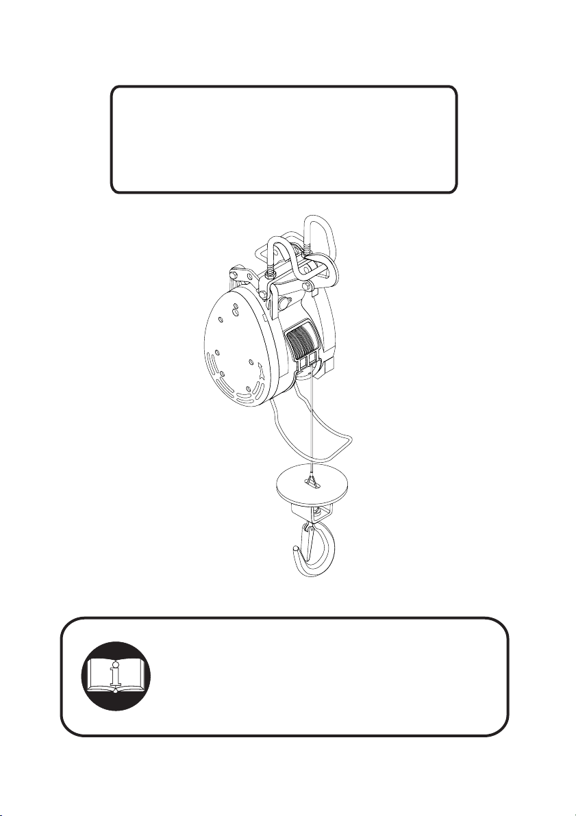
Instruction Manual
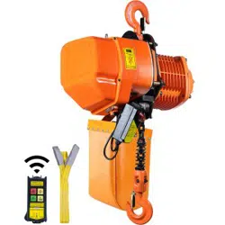
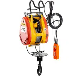
Mini Electric Winch
S-series,T-series,M-series
READY THIS MANUAL BEFORE USING THESE PRODUCTS
This manual contains important safety, installation, operation
and maintenance information. Make this manual available
to all persons responsible for the operation, installation and
maintenance of the mini electric winch.

1 18
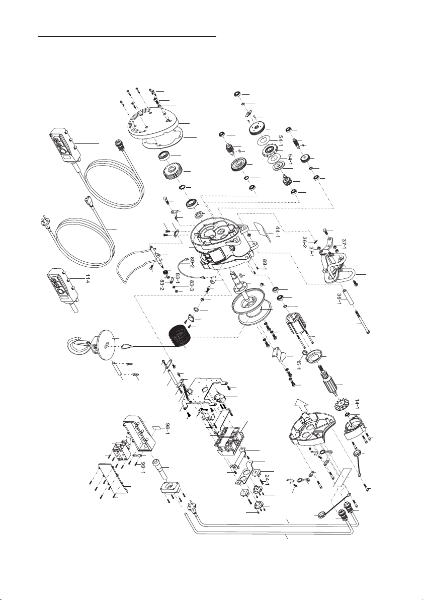
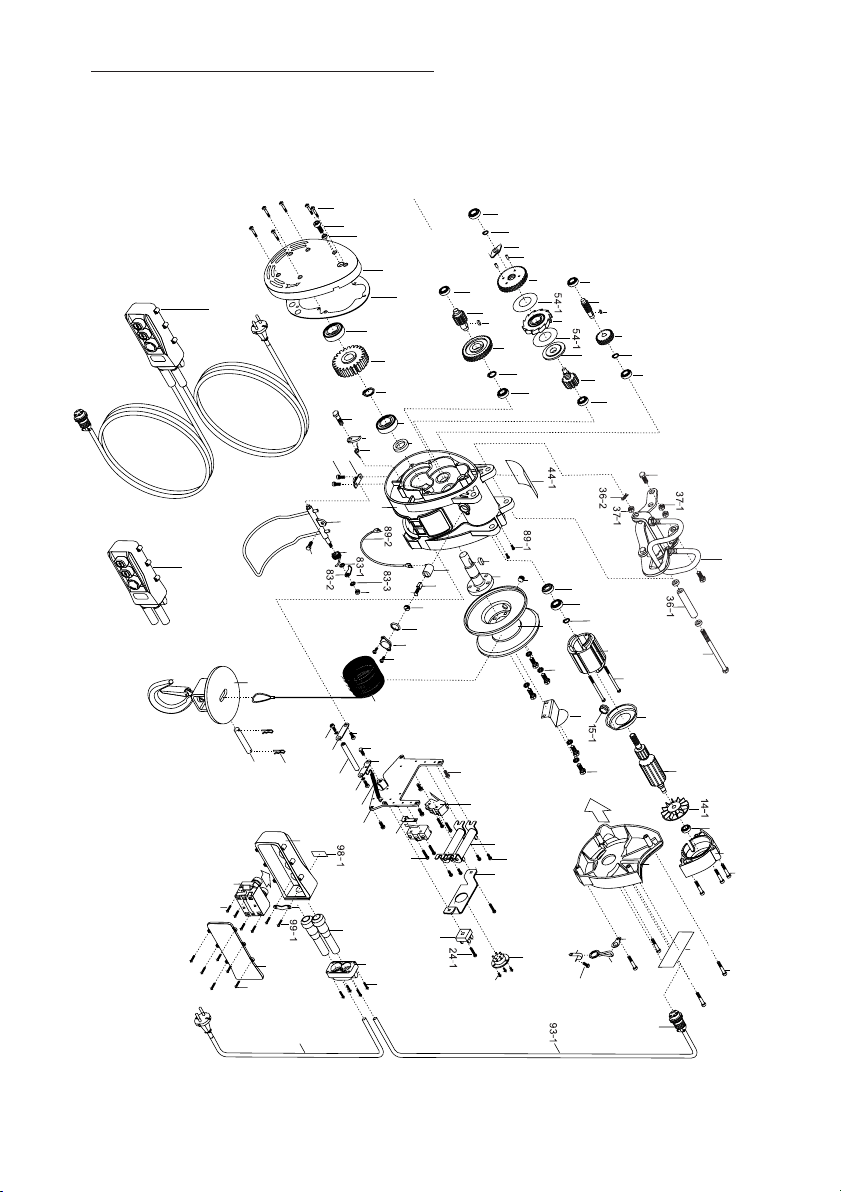
10. Parts list
Table of Contents
No. Parts Description
1 Motor Cover
2 Socket Bolt
3 Socket Bolt
4 Label
5 Rectifier Fixing Plate (M)
5-1 Screw (M)
6 Wiring Box Cover
7 Power Cable Connector
7-1 Screw
8 Contact Fixing Plate (M)
9 Control Connector Fixing Plate
10 Micro Switch
11 Screw
11-1 Fixing Plate
12 Switch Cable Connector
12-1 Screw
13 Bearing
14 Rotator
14-1 Fan
15 Air Guiding Cover
15-1 Insulating Sleeve
16 Circlip
17 Bearing
18 Oil Seal
19 Stator
20 Socket Bolt
21 Terminal Block(T)
22 Screw (T)
23 Electromagnetic Contactor (M)
24 Bridge Rectifier
24-1 Screw
25 Resistor
26 Screw
27 Wiring Rack
28 Screw
28-1 Washer
29 Limit Lever Fixing Plate
30 Limit Lever Fixing Plate
30-1 Screw
31 Anti-reverse Reel Push Rod
32 Spring
33 Screw
34 Screw
35 Upper Hook Set
36 Hex Bolt
36-1 Sleeve
No. Parts Description
37-1 Nut
37 Hex Bolt
36-2 R Pin
38 Reel Drum
39 Wire Rope Fixing Screw
40 Screw
40-1 Spring Washer
41 Wire Rope Side Cover
42 Output Shaft
43 key
44 Main Body Base
44-1 Sticker
45 Bearing
46 Circlip
47 First Reduction Gear
48 Key
49 First Reduction Pinion
50 Bearing
51 Bearing
52 Second Reduction Pinion
53 Brake Disk
54 Ratchet Disc
54-1 Copper Washer
55 Second Reduction Gear
56 Spring Pin
57 Rotary Stop Plate
58 Circlip
59 Bearing
60 Gasket
61 Gear Cover
62 Oil Seal
63 Socket Bolt
65 Socket Bolt
66 Bearing
67 Circlip
68 Third Reduction Gear
69 Key
70 Third Reduction Pinion
71 Bearing
72 Oil Seal
73 Bearing
74 Circlip
75 Fourth Reduction Gear
76 Bearing
77 Pawl Screws
78 Pawl
79 Pawl Spring
80 Screw
No. Parts Description
81 Screw
82 Upper Limit Holder
83 Spring
83-1 Washer
83-2 Upper Limit Push Rod
83-3 Washer
83-4 Nut
84 Upper Limit
85 Wire Rope
86 R Pin
87 Wire Rope Fixing Pin
88 Lower Hook Set
89 Carbon Brush Base
89-1 Screw
89-2 Carbon Base Cable
90 Carbon Brush
91 Carbon Brush Cover
92 O Ring
92-1 Protective Cap
92-2 Screw
93 Switch with Cable Set
93-1 Switch Cable
93-2 Switch Cable Connector
94 Power Cable Set
94-1 Power Cable With Plug
94-2 Power Cable Connector
95 Cable Support
96 Cable Support Socket
97 Screw
98 Switch Box
98-1 Sticker
99 Cable Fixing Plate
99-1 Screw
100 Internal Switch Contact
101 Screw
102 Switch Cover
103 Screw
104 PLT Cover Protection(T)
105 PLT Cover Protection(T)
106 Twin -Hole Hook
107 Switch Cable Hanger
108 Screw
109 Cable Fixing Clip
114 Switch without Cable
1.Specifications and Dimensions ..................................2
2. Precautions
2.1 General Safety Precautions ................................3
2.2 Environmental Precaution ....................................3
2.3 Handing Precautions .........................................4
3.Installation ...................................................................5
3.1 Winch Assembly....................................................5
3.2 Mounting...............................................................5
3.3 Plug Insertion............................................... ........5
4.Winch Principles
4.1
4.2
5. Maintenance and Replacement
5.1 Carbon Brush Replacement ...............................7
5.2 Wire Rope Replacement ....................................8
5.3 Oil Lubrication.......................................................8
6.Checking Reference.....................................................9
7.Trouble Shootings....... ..............................................10
8. Wiring Diagram..........................................................11
9. Parts Drawing S-Series-160kg,180kg,230kg,250kg,300kg.....12
Parts Drawing T-Series-160kg,180kg,230kg,250kg,300kg......13
Parts Drawing M-Series-160kg,180kg,230kg,250kg,300kg.....14
Parts Drawing S-Series-280kg,360kg,500kg...........................15
Parts Drawing T-Series-280kg,360kg,500kg...........................16
Parts Drawing M-Series-280kg,360kg,500kg..........................17
10. Parts List .............................................................18
Percentage Duty Cycle (%ED) ...........................6
Load Rated...........................................................6
4.3 Braking.................................................................6
4.4 Over-winding Lift Prevention................................7
4.5 Reverse-Winding Prevention...............................7

1 18
10. Parts list
Table of Contents
No. Parts Description
1 Motor Cover
2 Socket Bolt
3 Socket Bolt
4 Label
5 Rectifier Fixing Plate (M)
5-1 Screw (M)
6 Wiring Box Cover
7 Power Cable Connector
7-1 Screw
8 Contact Fixing Plate (M)
9 Control Connector Fixing Plate
10 Micro Switch
11 Screw
11-1 Fixing Plate
12 Switch Cable Connector
12-1 Screw
13 Bearing
14 Rotator
14-1 Fan
15 Air Guiding Cover
15-1 Insulating Sleeve
16 Circlip
17 Bearing
18 Oil Seal
19 Stator
20 Socket Bolt
21 Terminal Block(T)
22 Screw (T)
23 Electromagnetic Contactor (M)
24 Bridge Rectifier
24-1 Screw
25 Resistor
26 Screw
27 Wiring Rack
28 Screw
28-1 Washer
29 Limit Lever Fixing Plate
30 Limit Lever Fixing Plate
30-1 Screw
31 Anti-reverse Reel Push Rod
32 Spring
33 Screw
34 Screw
35 Upper Hook Set
36 Hex Bolt
36-1 Sleeve
No. Parts Description
37-1 Nut
37 Hex Bolt
36-2 R Pin
38 Reel Drum
39 Wire Rope Fixing Screw
40 Screw
40-1 Spring Washer
41 Wire Rope Side Cover
42 Output Shaft
43 key
44 Main Body Base
44-1 Sticker
45 Bearing
46 Circlip
47 First Reduction Gear
48 Key
49 First Reduction Pinion
50 Bearing
51 Bearing
52 Second Reduction Pinion
53 Brake Disk
54 Ratchet Disc
54-1 Copper Washer
55 Second Reduction Gear
56 Spring Pin
57 Rotary Stop Plate
58 Circlip
59 Bearing
60 Gasket
61 Gear Cover
62 Oil Seal
63 Socket Bolt
65 Socket Bolt
66 Bearing
67 Circlip
68 Third Reduction Gear
69 Key
70 Third Reduction Pinion
71 Bearing
72 Oil Seal
73 Bearing
74 Circlip
75 Fourth Reduction Gear
76 Bearing
77 Pawl Screws
78 Pawl
79 Pawl Spring
80 Screw
No. Parts Description
81 Screw
82 Upper Limit Holder
83 Spring
83-1 Washer
83-2 Upper Limit Push Rod
83-3 Washer
83-4 Nut
84 Upper Limit
85 Wire Rope
86 R Pin
87 Wire Rope Fixing Pin
88 Lower Hook Set
89 Carbon Brush Base
89-1 Screw
89-2 Carbon Base Cable
90 Carbon Brush
91 Carbon Brush Cover
92 O Ring
92-1 Protective Cap
92-2 Screw
93 Switch with Cable Set
93-1 Switch Cable
93-2 Switch Cable Connector
94 Power Cable Set
94-1 Power Cable With Plug
94-2 Power Cable Connector
95 Cable Support
96 Cable Support Socket
97 Screw
98 Switch Box
98-1 Sticker
99 Cable Fixing Plate
99-1 Screw
100 Internal Switch Contact
101 Screw
102 Switch Cover
103 Screw
104 PLT Cover Protection(T)
105 PLT Cover Protection(T)
106 Twin -Hole Hook
107 Switch Cable Hanger
108 Screw
109 Cable Fixing Clip
114 Switch without Cable
1.Specifications and Dimensions ..................................2
2. Precautions
2.1 General Safety Precautions ................................3
2.2 Environmental Precaution ....................................3
2.3 Handing Precautions .........................................4
3.Installation ...................................................................5
3.1 Winch Assembly....................................................5
3.2 Mounting...............................................................5
3.3 Plug Insertion............................................... ........5
4.Winch Principles
4.1
4.2
5. Maintenance and Replacement
5.1 Carbon Brush Replacement ...............................7
5.2 Wire Rope Replacement ....................................8
5.3 Oil Lubrication.......................................................8
6.Checking Reference.....................................................9
7.Trouble Shootings....... ..............................................10
8. Wiring Diagram..........................................................11
9. Parts Drawing S-Series-160kg,180kg,230kg,250kg,300kg.....12
Parts Drawing T-Series-160kg,180kg,230kg,250kg,300kg......13
Parts Drawing M-Series-160kg,180kg,230kg,250kg,300kg.....14
Parts Drawing S-Series-280kg,360kg,500kg...........................15
Parts Drawing T-Series-280kg,360kg,500kg...........................16
Parts Drawing M-Series-280kg,360kg,500kg..........................17
10. Parts List .............................................................18
Percentage Duty Cycle (%ED) ...........................6
Load Rated...........................................................6
4.3 Braking.................................................................6
4.4 Over-winding Lift Prevention................................7
4.5 Reverse-Winding Prevention...............................7
17 2
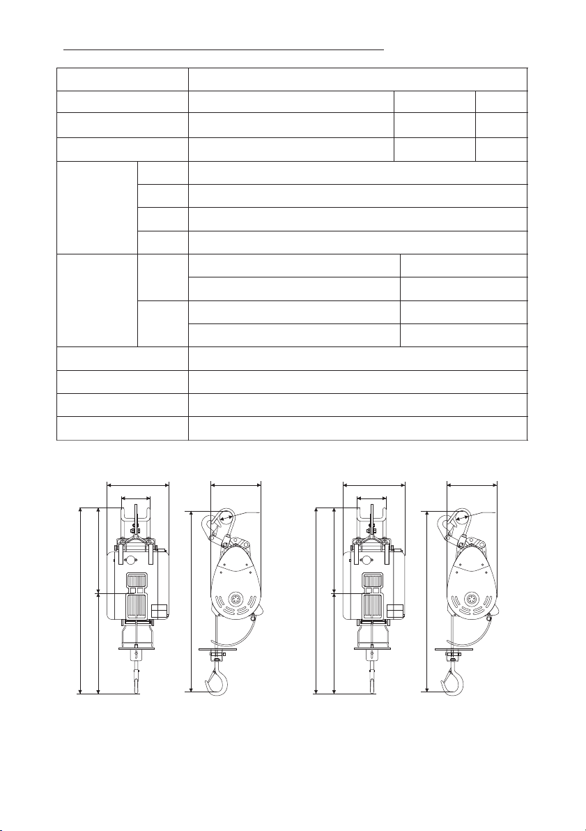
1. Specifications and Dimensions
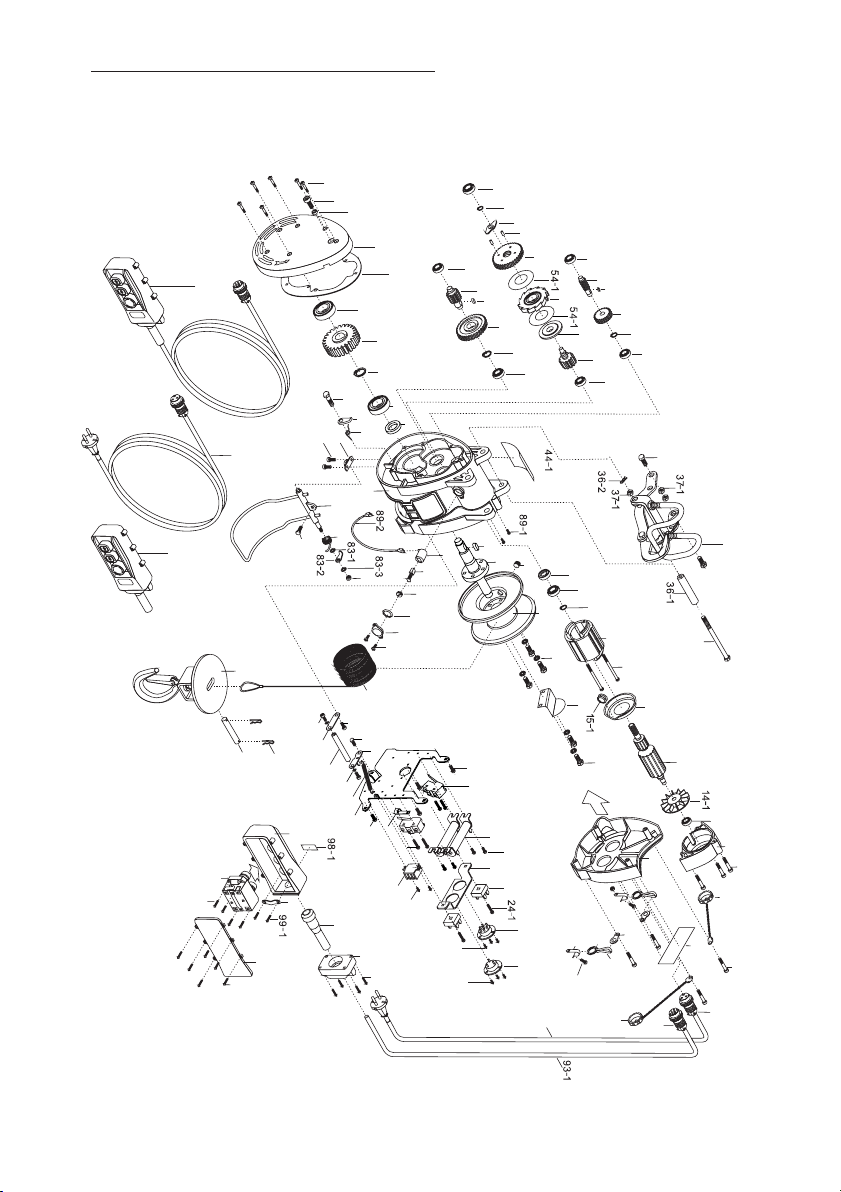
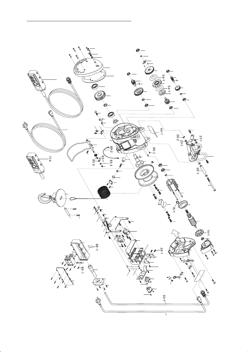
9.Parts drawing M-Series
280kg,360kg,500kg
Model S-series T-series M-series
Rated Load 160kg/180kg/230kg/250kg/300kg 280kg/360kg 500kg
Lifting Height 30m 60m 30m
Wire Rope Dia. 5mm 5mm 6mm
1200W 160kg
1300W 180kg/230kg/280kg
1600W 300kg/360kg/500kg
1500W 250kg
Motor
Lifting
Speed
50Hz
60Hz
160kg/180kg/230kg/250kg/300kg 19m/min
160kg/180kg/230kg/250kg/300kg 23m/min
280kg/360kg/500kg 13m/min
280kg/360kg/500kg 15m/min
Power Supply Single-phase, 110V-220V, 220-240V, AC 50/60Hz
Duty Cycle ED 25% Max. on time: 15min/hr. Max. number of starts: 150/hr
International protect 54
Insulation Class F
240
182
115
360 280
640
695
Ø60
160Kg,180Kg,230Kg,250KG,300KG
238
210
145
400 300
750
695
Ø60
280Kg 360Kg 500Kg
37
36
35
50
49
48
47
46
45
51
52
54
65
59
58
57
56
55
71
70
69
68
67
66
75
76
74
73
79
78
77
82
81
63
62
61
60
44
85
89
90
91
88
80
43
38
16
17
18
19
20
41
15
14
13
1
104
2
3
4
94-2
93-2
107
93-1
6
109
108
97
99
98
100
101
102
103
95
3
9
9
28
29
31
32
27
25
26
12
12-1
7
23
24
72
40-1
40
39
83-4
105
9
4
106
94-1
28-1
11-1
11
34
30
33
30-1
34
92
92-1
92-2
7-1
23
11-1
11
34
8
26
10
53
83
84
42
96
86
87
17 2
1. Specifications and Dimensions
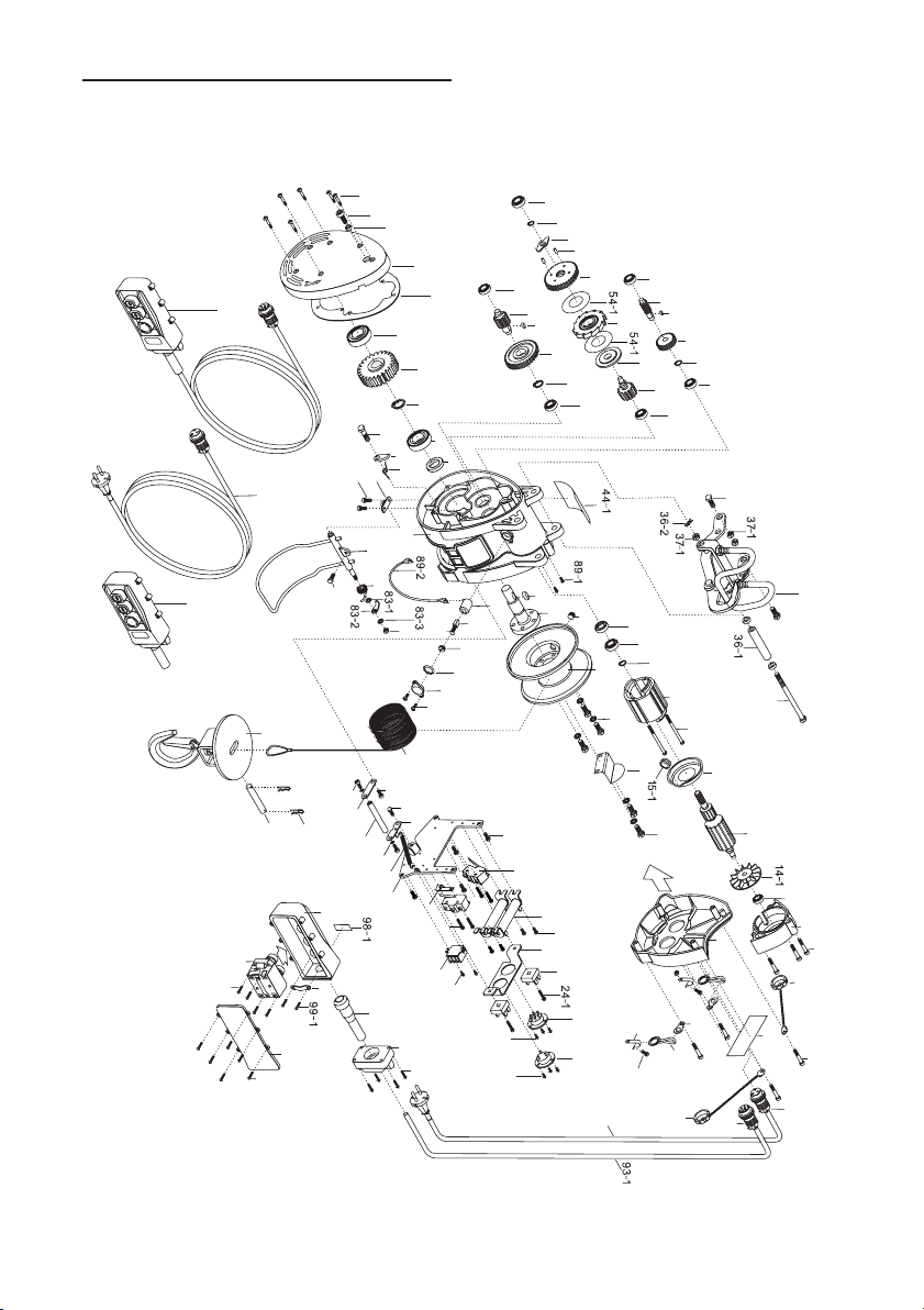
9.Parts drawing M-Series
280kg,360kg,500kg
Model S-series T-series M-series
Rated Load 160kg/180kg/230kg/250kg/300kg 280kg/360kg 500kg
Lifting Height 30m 60m 30m
Wire Rope Dia. 5mm 5mm 6mm
1200W 160kg
1300W 180kg/230kg/280kg
1600W 300kg/360kg/500kg
1500W 250kg
Motor
Lifting
Speed
50Hz
60Hz
160kg/180kg/230kg/250kg/300kg 19m/min
160kg/180kg/230kg/250kg/300kg 23m/min
280kg/360kg/500kg 13m/min
280kg/360kg/500kg 15m/min
Power Supply Single-phase, 110V-220V, 220-240V, AC 50/60Hz
Duty Cycle ED 25% Max. on time: 15min/hr. Max. number of starts: 150/hr
International protect 54
Insulation Class F
240
182
115
360 280
640
695
Ø60
160Kg,180Kg,230Kg,250KG,300KG
238
210
145
400 300
750
695
Ø60
280Kg 360Kg 500Kg
37
36
35
50
49
48
47
46
45
51
52
54
65
59
58
57
56
55
71
70
69
68
67
66
75
76
74
73
79
78
77
82
81
63
62
61
60
44
85
89
90
91
88
80
43
38
16
17
18
19
20
41
15
14
13
1
104
2
3
4
94-2
93-2
107
93-1
6
109
108
97
99
98
100
101
102
103
95
3
9
9
28
29
31
32
27
25
26
12
12-1
7
23
24
72
40-1
40
39
83-4
105
9
4
106
94-1
28-1
11-1
11
34
30
33
30-1
34
92
92-1
92-2
7-1
23
11-1
11
34
8
26
10
53
83
84
42
96
86
87

The winch has been designed to give safe and dependable service if operated according
to the instructions. Please read and understand this manual before installation and
operation of the winch.
Follow these general safety precautions:
● Confirm that the winch complies with the using conditions.
● Keep the winch secure strongly and the rope is not wound to be deviated to the drum.
● Don't use unsuitable pulleys or accessories concerned.
● Don't use unsuitable rope in construction, strength or having any defects.
● Pay attention to the grounding, it provides a path of least resistance for electric
current to reduce the risk of shock.
● Check the winch for smooth operation without load before loading operation.
● Make sure the wire rope to be wound evenly in the first layer on the drum, rewind it
if a mixed windings in existence.
● If a wire rope is found an uneven winding or accumulated at one side of the drum,
align it adequately.
1. The winch is not to be used to life, support or otherwise transport personnel.
2. A minimum of five (5) wraps of rope around the drum is necessary to support the load
rated.
3. The owner and / or the operator shall have an understanding of these operating
instructions and the warning before operating the electrical winch. Failure to follow
these warnings may result in loss of load, damage to the winch, property damage,
personal, or fatal injury.
4. The owner shall retain this manual for further reference to important warnings,
installation, operating and maintenance instructions.
2.1 General Safety Precautions
2.2 Environmental Precaution
The following environmental conditions may result in the possible causes of
winch trouble.
● Low temperature below -10°, high temperature above 40° or humidity
above 90% conditions.
● In an organic chemistry or explosive power conditions.
● In heavy acid or salty conditions.
● In the rain or snow condition.
● In a heavy general powder conditions.
3 16
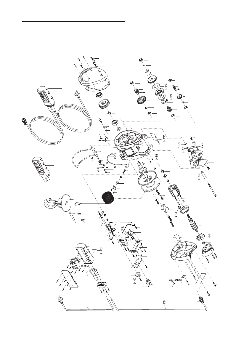
9. Parts drawing T-Series
2. Precautions
280kg,360kg,500kg
WARNING
WARNING
50
49
48
47
46
45
51
52
54
65
59
58
57
56
55
71
70
69
68
67
66
75
76
74
73
79
78
77
82
81
63
62
61
60
44
85
89
90
91
88
43
38
16
17
18
19
20
41
15
14
13
1
104
2
3
6
4
105
107
109
108
97
99
98
100
101
102
103
95
3
9
9
4
11
4
9
28
29
31
32
27
25
24
12
12-1
7
21
22
72
106
40-1
40
39
83-4
94-1
94-2
93-2
28-1
26
11-1
11
34
30
33
30-1
92
92-1
92-2
7-1
34
10
53
83
84
80
42
96
86
87
37
36
35
The winch has been designed to give safe and dependable service if operated according
to the instructions. Please read and understand this manual before installation and
operation of the winch.
Follow these general safety precautions:
● Confirm that the winch complies with the using conditions.
● Keep the winch secure strongly and the rope is not wound to be deviated to the drum.
● Don't use unsuitable pulleys or accessories concerned.
● Don't use unsuitable rope in construction, strength or having any defects.
● Pay attention to the grounding, it provides a path of least resistance for electric
current to reduce the risk of shock.
● Check the winch for smooth operation without load before loading operation.
● Make sure the wire rope to be wound evenly in the first layer on the drum, rewind it
if a mixed windings in existence.
● If a wire rope is found an uneven winding or accumulated at one side of the drum,
align it adequately.
1. The winch is not to be used to life, support or otherwise transport personnel.
2. A minimum of five (5) wraps of rope around the drum is necessary to support the load
rated.
3. The owner and / or the operator shall have an understanding of these operating
instructions and the warning before operating the electrical winch. Failure to follow
these warnings may result in loss of load, damage to the winch, property damage,
personal, or fatal injury.
4. The owner shall retain this manual for further reference to important warnings,
installation, operating and maintenance instructions.
2.1 General Safety Precautions
2.2 Environmental Precaution
The following environmental conditions may result in the possible causes of
winch trouble.
● Low temperature below -10°, high temperature above 40° or humidity
above 90% conditions.
● In an organic chemistry or explosive power conditions.
● In heavy acid or salty conditions.
● In the rain or snow condition.
● In a heavy general powder conditions.
3 16
9. Parts drawing T-Series
2. Precautions
280kg,360kg,500kg
WARNING
WARNING
50
49
48
47
46
45
51
52
54
65
59
58
57
56
55
71
70
69
68
67
66
75
76
74
73
79
78
77
82
81
63
62
61
60
44
85
89
90
91
88
43
38
16
17
18
19
20
41
15
14
13
1
104
2
3
6
4
105
107
109
108
97
99
98
100
101
102
103
95
3
9
9
4
11
4
9
28
29
31
32
27
25
24
12
12-1
7
21
22
72
106
40-1
40
39
83-4
94-1
94-2
93-2
28-1
26
11-1
11
34
30
33
30-1
92
92-1
92-2
7-1
34
10
53
83
84
80
42
96
86
87
37
36
35
2.3 Handing Precautions
●To prevent the risk of electric shock, the power plug must be plugged into a matching
outlet and grounded in good condition.
●Never try to lift a load higher than the rated cap.
●Never hitch a ride on the hook, sling or load being moving.
●Winches are not to be used for lifting or lowering people.
●Don't work, walk or stand under an operating winch.
●Always remain in control. Never neglect the winch while actually hoisting a load.
●While working, never stand under a lifting load or within the conveying area.
●Always look up when working around winch, there is potential danger overhead.
●Never gravitate a load free.
●Be sure to lift a load vertically. Slack may allow wires to be caught in The drum.
●Prior to starting of use, carry out the daily checking without fail, and after confirming
the safety of function. If having a counter rotation incurred, make sure to correct
its rotation direction.
●Prior to lifting. Make sure to have a precise performance of brake. If any malfunction
of brake happened, stop the operation immediately.
●When load suspended in air, it will not allow to be welding.
●Wire rope with one or more of the following defects shall be removed or replaced
immediately.
1) kink, 2) distortion, 3) corrosion, 4) Broken wires more than 10%,
5). Decreasing of diameter more than 7%
●Stop the operation if there is any queer noise or vibration in the gear box
to be happened.
●Do not connect the wire rope with the grounding of welding machine.
●While welding, do not have any contact with the welding objects because of
having spark.
●Do not pull the switch.
●Never plugging (instant reverse-winding) or inching.
●Do not over the short time ratings of the winch.
●In order to prevent the layer down due to over loosening of rope irregular winding,
etc., operate according to the suitable operating method.
●Use a winch by fixing so securely that the rope around the drum is even.
●Be sure to fix a rope in the center of weight hook.
●Avoid catching the hook or lifting a load on a fixed obstruction.
●Always leave the pendant switch positioned immediately after use.
●Make sure that the load being lifting is well balanced and secured before starting.
●Avoid water splashes on the pendant switch.
15 4
2. Precautions
9. Parts drawing S-Series
280kg,360kg,500kg
●Never wrap the load with the wire rope.
50
49
48
47
46
45
51
52
54
65
59
58
57
56
55
71
70
69
68
67
66
75
76
74
73
79
78
77
82
81
63
62
61
60
44
83
85
89
90
91
88
86
87
43
38
16
17
18
19
20
41
15
14
13
1
2
3
6
4
107
109
108
97
99
98
100
101
102
103
95
93
114
9
28
29
31
32
27
25
24
7
72
106
40-1
40
39
83-4
94-1
93-2
28-1
26
11-1
11
30
33
30-1
92
92-1
92-2
7-1
34
10
53
84
80
42
96
37
36
35
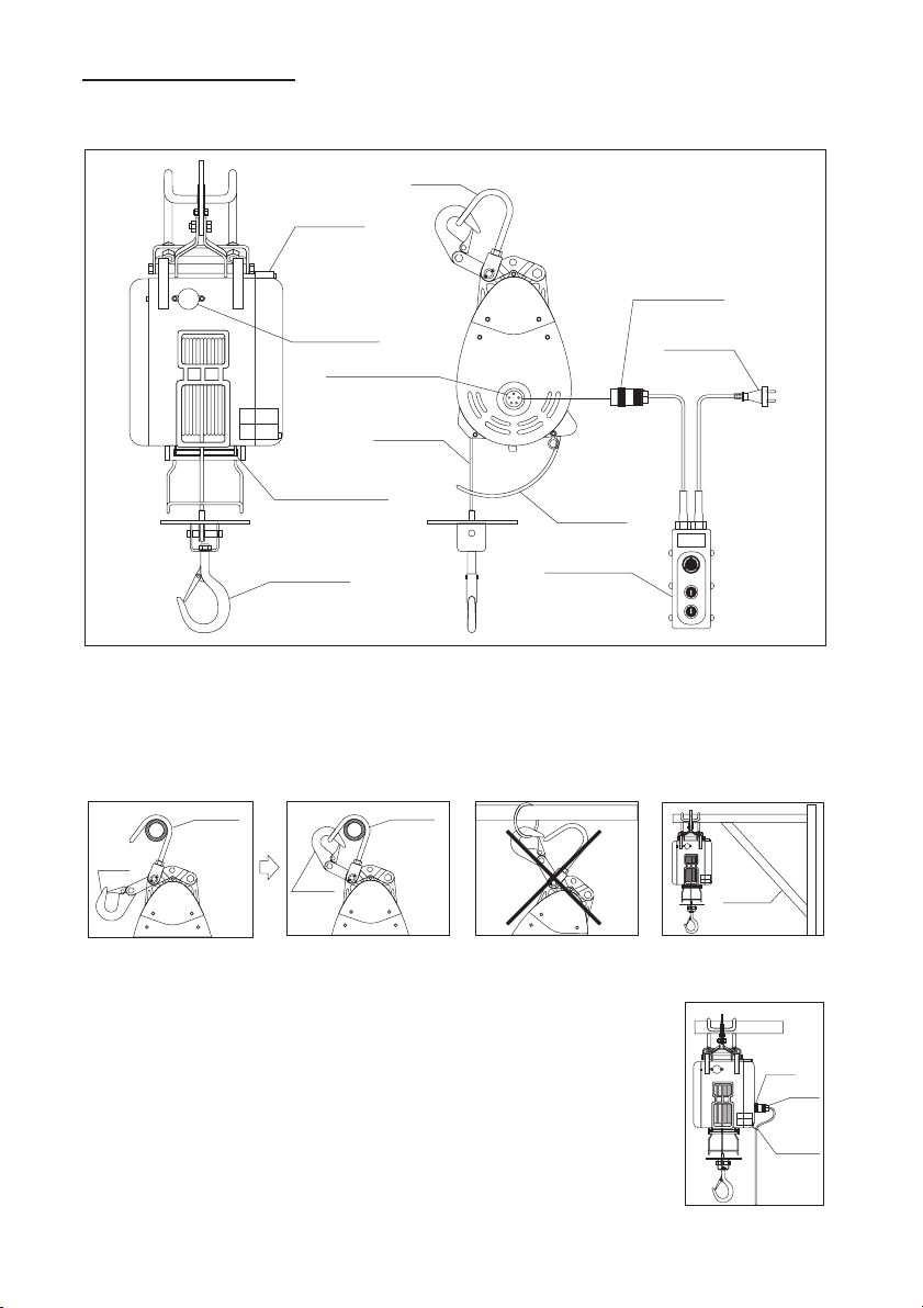
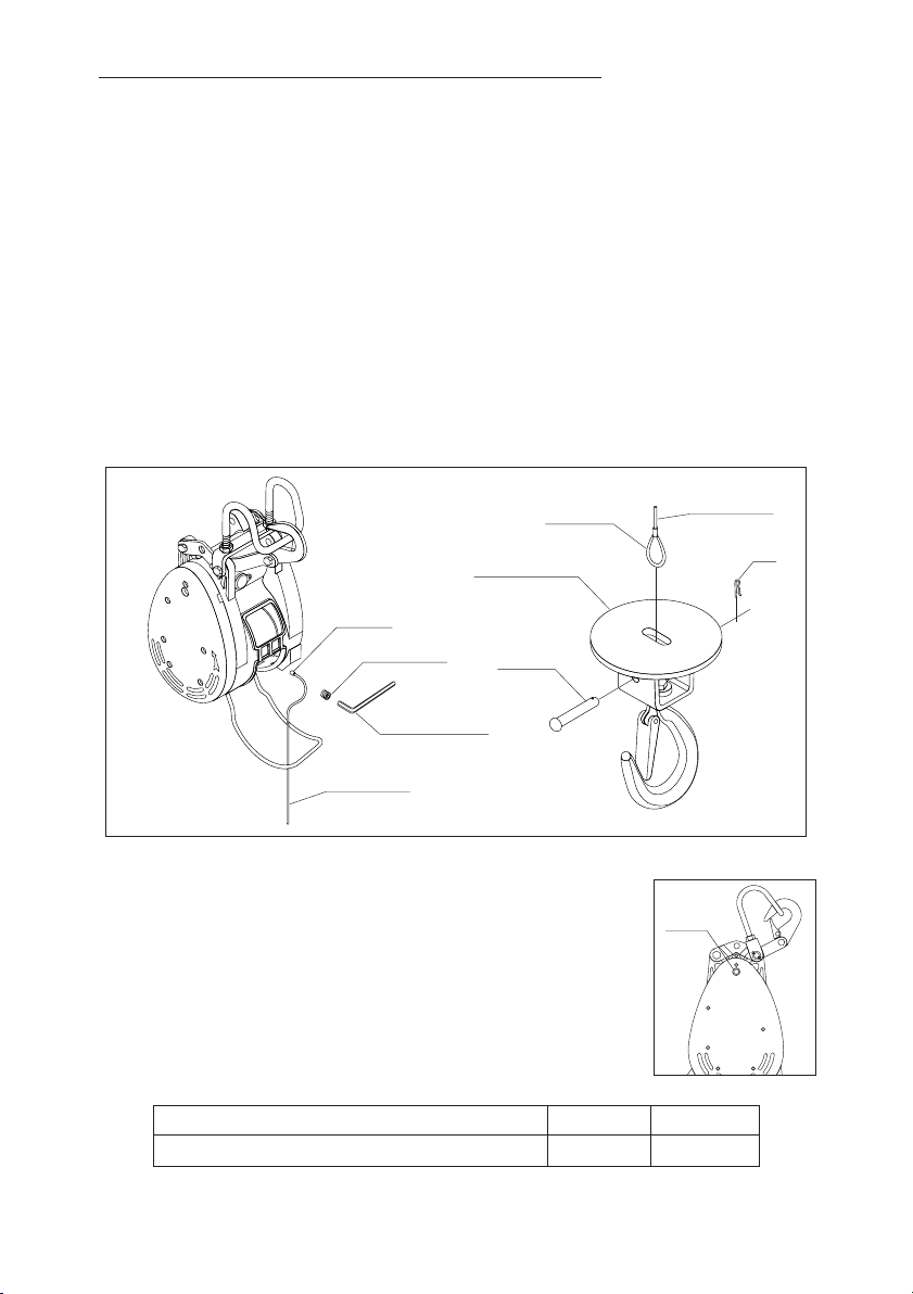
3.1 Winch Assembly
STOP
Winch body
Brush holder
Reverse winding
limit lever
Hanger
Wire rope
Over -winding
limit lever
Switch receptacle
Switch connector
Power plug
Pendant switch
Weight hook
3.2 Mounting
Hook
Hanger
Hanger
Hook
3.3 Plug insertion
●
and clockwise tighten it by turning the locking ring.Be sure to
lock the lead by a holder. Do not allow it to be caught by wire
rope, drum or other obstacle.
Insert the power plug into the power receptacle of the winch,
● The length of power cord is subject to the distance of 20
meter, for any other cases, please use a bigger section cord
such as 2.0 mm or 3.5 mm or a magnetic switch equipped to
prevent a considerable voltage drop to be happened.
Bracket
Fixing
ring
Plug
Holder
The winch designed to be hanged or mounted on a firm or stable bar or a bracket. When
hanging, do not allow the body or load to be caught by any construction of frame, or
other obstruction. Be sure to lock the hanger for extra safety.
5 14
9. Parts drawing M-Series
3. Installation
160kg,180kg,230kg,250kg,360kg
50
49
48
47
46
45
51
52
54
65
59
58
57
56
55
71
70
69
68
67
66
75
76
74
73
79
78
77
82
81
63
62
61
60
44
85
89
90
91
88
43
38
16
17
18
19
20
41
15
14
13
1
2
3
4
107
94
6
109
108
97
99
98
100
101
102
103
95
3
9
9
5
28
29
31
32
27
8
25
12
7
23
26
24
83-4
39
72
106
40-1
40
9
4
93-2
28-1
11-1
11
30
33
30-1
12-1
7-1
5-1
92
92-1
92-2
34
10
53
83
84
80
42
96
86
87
37
36
35
4.1 Percentage Duty Cycle
Never hoist over the rated percentage duty cycle.
WARNING
The life of the winch is depending on the conditions of the load and working frequency.
In the long time operation, make sure to use the machine within its short time ratings.
Short time ratings means the working duty cycle is subject to the rated voltage, rated
frequency and a 63% of rated load. All mini winches are rated 25% percentage duty cycle.
percentage duty cycle= %
Operating hours
Operating hours+ stopping hours.
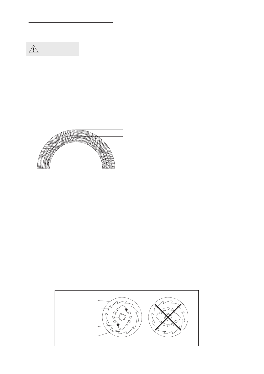
4.2 Load Rated
Top layer (Max.speed Min.load)
Half layer (Med.speed Med.load)
First layer (Min.speed Max.load)
4.3 Braking
2nd /3rd Gear
3rd /4th Shaft
Ratchet
Spring pin
Fix plate
●Braking device is composed of a mechanic brake and an electronic generated brake.
The brake distance from the time of braking until stopping completely should be within
1.5% of rope length to the wound in during 1 minute.
●Owing to the rope speed on no load is 1.5 -1.8 times faster than that on rated load,
the brake distance on no load will be longer, but still within 1.5% of rope length.
●It is highly recommended that any adjustments are carried out by a qualified technician
at an authorized service center.
●Brake adjustment procedures.
Step 1. Remove retaining ring and spring pin.
Step 2. Tighten 3rd gear / 4th shaft counter-clockwise until holding to the ratchet.
Step 3. Find the closed pole between spring pins and fit plate
(one between
four selections), then put the fix plate onto the square hole
of 3rd or 4th shaft.
Step 4. Insert spring pins and lock retaining ring.
13 6
4. Winch principles
8. Parts drawing T-seriel
160kg, 180kg, 230kg,250kg,300kg
50
49
48
47
46
45
51
52
54
65
59
58
57
56
55
71
70
69
68
67
66
75
76
74
73
79
78
77
82
81
63
62
61
60
44
85
89
90
91
88
43
38
16
17
18
19
20
41
15
14
13
1
104
2
3
6
4
105
107
109
108
97
99
98
100
101
102
103
95
3
9
9
4
11
4
9
28
29
31
32
27
25
24
12
7
21
22
39
83-4
72
106
40-1
40
94-1
94-2
93-2
28-1
26
11-2
11-1
33
34
33-1
12-1
92
92-1
92-2
7-1
34
10
53
83
84
80
42
96
86
87
37
36
35
4.1 Percentage Duty Cycle
Never hoist over the rated percentage duty cycle.
WARNING
The life of the winch is depending on the conditions of the load and working frequency.
In the long time operation, make sure to use the machine within its short time ratings.
Short time ratings means the working duty cycle is subject to the rated voltage, rated
frequency and a 63% of rated load. All mini winches are rated 25% percentage duty cycle.
percentage duty cycle= %
Operating hours
Operating hours+ stopping hours.
4.2 Load Rated
Top layer (Max.speed Min.load)
Half layer (Med.speed Med.load)
First layer (Min.speed Max.load)
4.3 Braking
2nd /3rd Gear
3rd /4th Shaft
Ratchet
Spring pin
Fix plate
●Braking device is composed of a mechanic brake and an electronic generated brake.
The brake distance from the time of braking until stopping completely should be within
1.5% of rope length to the wound in during 1 minute.
●Owing to the rope speed on no load is 1.5 -1.8 times faster than that on rated load,
the brake distance on no load will be longer, but still within 1.5% of rope length.
●It is highly recommended that any adjustments are carried out by a qualified technician
at an authorized service center.
●Brake adjustment procedures.
Step 1. Remove retaining ring and spring pin.
Step 2. Tighten 3rd gear / 4th shaft counter-clockwise until holding to the ratchet.
Step 3. Find the closed pole between spring pins and fit plate
(one between
four selections), then put the fix plate onto the square hole
of 3rd or 4th shaft.
Step 4. Insert spring pins and lock retaining ring.
13 6
4. Winch principles
8. Parts drawing T-seriel
160kg, 180kg, 230kg,250kg,300kg
50
49
48
47
46
45
51
52
54
65
59
58
57
56
55
71
70
69
68
67
66
75
76
74
73
79
78
77
82
81
63
62
61
60
44
85
89
90
91
88
43
38
16
17
18
19
20
41
15
14
13
1
104
2
3
6
4
105
107
109
108
97
99
98
100
101
102
103
95
3
9
9
4
11
4
9
28
29
31
32
27
25
24
12
7
21
22
39
83-4
72
106
40-1
40
94-1
94-2
93-2
28-1
26
11-2
11-1
33
34
33-1
12-1
92
92-1
92-2
7-1
34
10
53
83
84
80
42
96
86
87
37
36
35
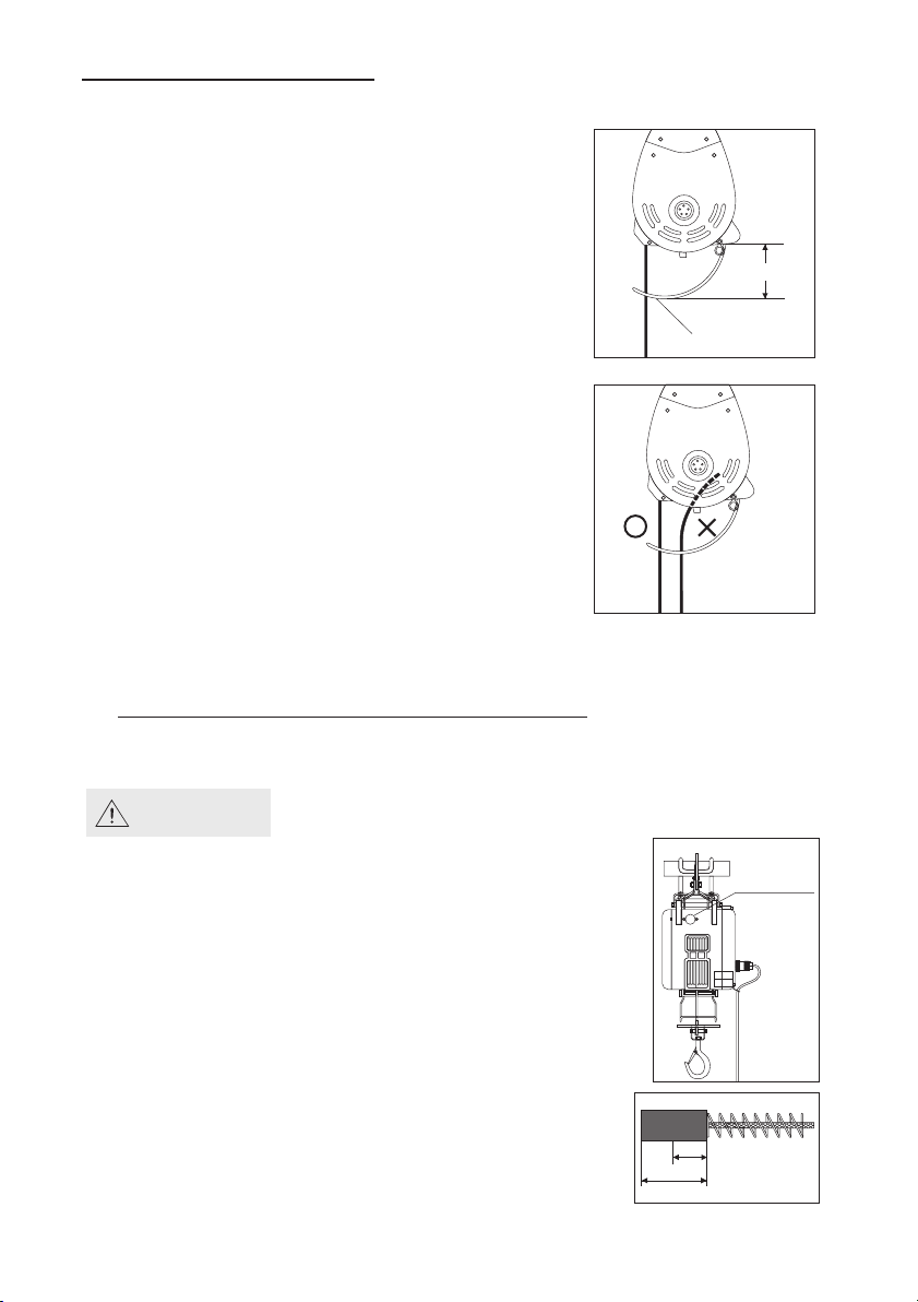
Over-winding
limit lever
70-90mm
●A special mechanism prevents an over-winding
when lifting.
●When the weight hook touches the limit lever.
Lifting is automatically stopped.
●However, if the limit lever is set too close to the
winch body, it will cause serious damage to the
limit lever and the winch body.
●A suggested distance (S) between the limit lever
and winch bottom is as follows.
4.4 Over-winding Lift Prevention
4.5 Reverse-Winding Prevention
●A special mechanism prevents a reverse-winding
when lowering.
●When lowering, a wire rope is fully extended,
the wire rope will be shifted its position from O to X.
●When a wire rope touches the limit lever of
over-winding prevention device. Lowing will be
automatically stopped.
●When the wire rope is shifted to the position of X,
pull it and press the ↑ button to return its position to O.
5. Maintenance and Replacement
5.1 Carbon Brush Replacement
WARNING
Clean the accumulated powder of carbon brush
periodically to ascertain the insulation resistance
up to 1 MΩ.
●It is essential to check the carbon brush periodically. If its
length is left less than 7.5 mm resulting from wear, it is
absolute necessary to replace carbon brush immediately.
While replacing, smoothly insert carbon brush into carbon●
holder in the first place, then put brush cap into the hole.
Before tightening the carbon brush holder, make sure to●
position O-ring.
A set of carbon brush consists 2 piece of carbon brush.●
Ascertain to replace 2 pieces of carbon brush on opposite
sides of winch body at the same time.
7.5
17
Carbon brush
carbon brush
holder
7
12
1. Parts drawing S-Series
4. Winch principles
160kg,180kg,230kg,250kg,300kg
50
49
48
47
46
45
51
52
53
54
65
59
58
57
56
55
71
70
69
68
67
66
75
76
74
73
72
79
78
77
82
81
63
62
61
60
44
83-4
84
85
89
90
91
88
43
42
38
16
17
18
19
40-1
20
41
40
15
14
13
1
2
3
6
4
106
107
94-1
109
108
97
99
98
100
101
102
103
95
93
114
9
33
28
29
31
28-1
30
30-1
32
27
10
11-1
25
24
11
26
7
7-1
39
92
92-1
92-2
93-2
34
83
80
96
86
87
37
36
35
P.T.screw
Hex.wrench
Clamp
Wire rope
Weight hook
Sleeve
Pin
Thimble
Wire rope
5.2 Wire Rope Replacement
Weight hook
●Put a new wire rope through the hole of the round plate of weight hook.
●Insert a sleeve pin through the thimble of wire rope.
●Insert a pin through the sleeve pin and bent it by pliers.
Drum
●Let a new wire rope w/clamp through the limit lever and insert it into the
hole of the drum.
●Put a P.T. screw into the hole of the drum and tighten it by a hexagon
wrench.
●Press the ↑ button to rotate the drum in the lifting direction.
●An uneven winding of wire rope may cause the load to be swing, that will
damage the rope and reducing its service life.
5.3 Oil Lubrication
Gear lubrication is an important component in insuring the
long life of your winch. The type of lubricant will have a great
influence. Winch are pre-lubricated at the factory and do not
require initial lubrication. Re-lubrication interval depends
upon service. Consult your local lubricant distributor on the
selection that best fits your climate and application.
Oil hole
Grease Grade Quantity Intervals
Caltex Multifak EP, Cosmogear Sp460 250 cc 1 Year
1
2
3
4
5
5
4
3
2
1
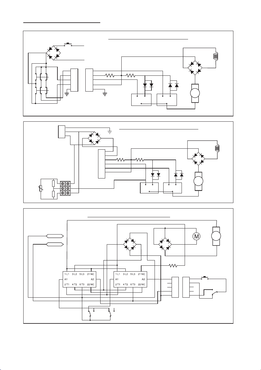
NO NC
COM
NO NC
COM
Yellow
Yellow
Black
Red
Up
Middle
Down
Red
Black
SW1
R2
16R 40W
P1 P0
Header5Header5
DR1
Bridge1
DR2
Bridge2
Motor
Stator
AC input2
AC input1
Control Circuit For M-series
1
2
3
4
5
Green
Yellow
White
Red
Black
NO
NC
NO
NC
Motor
Rotor
Motor
Rotor
Motor
Rotor
16Ω 16Ω
Bridge
Rectifier
Motor
Stator
Switch cord receptacle
1
2
3
4
5
Up
Down
Emergency
Button
ACV
Input
Control Circuit for S-series
1
2
3
4
5
6
7
White
Red
Black
NO
NC
NO
NC
16Ω 16Ω
Bridge
Rectifier
Motor
Stator
1
2
3
Control Circuit for T-series
Brown
Grey
Yellow
120K
120K
14D471K
Ar
Ar
Ar
L
L
L
R
R
R
11 8
5. Maintenance and Replacement
8. Wiring Diagram
P.T.screw
Hex.wrench
Clamp
Wire rope
Weight hook
Sleeve
Pin
Thimble
Wire rope
5.2 Wire Rope Replacement
Weight hook
●Put a new wire rope through the hole of the round plate of weight hook.
●Insert a sleeve pin through the thimble of wire rope.
●Insert a pin through the sleeve pin and bent it by pliers.
Drum
●Let a new wire rope w/clamp through the limit lever and insert it into the
hole of the drum.
●Put a P.T. screw into the hole of the drum and tighten it by a hexagon
wrench.
●Press the ↑ button to rotate the drum in the lifting direction.
●An uneven winding of wire rope may cause the load to be swing, that will
damage the rope and reducing its service life.
5.3 Oil Lubrication
Gear lubrication is an important component in insuring the
long life of your winch. The type of lubricant will have a great
influence. Winch are pre-lubricated at the factory and do not
require initial lubrication. Re-lubrication interval depends
upon service. Consult your local lubricant distributor on the
selection that best fits your climate and application.
Oil hole
Grease Grade Quantity Intervals
Caltex Multifak EP, Cosmogear Sp460 250 cc 1 Year
1
2
3
4
5
5
4
3
2
1
NO NC
COM
NO NC
COM
Yellow
Yellow
Black
Red
Up
Middle
Down
Red
Black
SW1
R2
16R 40W
P1 P0
Header5Header5
DR1
Bridge1
DR2
Bridge2
Motor
Stator
AC input2
AC input1
Control Circuit For M-series
1
2
3
4
5
Green
Yellow
White
Red
Black
NO
NC
NO
NC
Motor
Rotor
Motor
Rotor
Motor
Rotor
16Ω 16Ω
Bridge
Rectifier
Motor
Stator
Switch cord receptacle
1
2
3
4
5
Up
Down
Emergency
Button
ACV
Input
Control Circuit for S-series
1
2
3
4
5
6
7
White
Red
Black
NO
NC
NO
NC
16Ω 16Ω
Bridge
Rectifier
Motor
Stator
1
2
3
Control Circuit for T-series
Brown
Grey
Yellow
120K
120K
14D471K
Ar
Ar
Ar
L
L
L
R
R
R
11 8
5. Maintenance and Replacement
8. Wiring Diagram
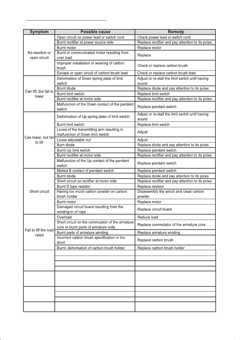
Fail to hold the
load after
stopping
The gap of ratchet brake is too large Adjust the ratchet brake
Malfunction of pressed spring of ratchet brake Replace pressed spring
The oil is too dirty or includes contamination Replace oil
Having too much oil in gear box Reduce the quantity of oil
Brake distance is
too long at no
load
Malfunction of D type resistor Check or replace D type resistor
Having smell or
smoke
Malfunction of pressed spring of ratchet brake Replace pressed spring
Burnt D type resistor Replace D type resistor
Malfunction of B contact of the pendant switch Replace pendant switch
Too noise whiling
lifting
The noise result from the click between ratchet
stopper and wheel
It is normal
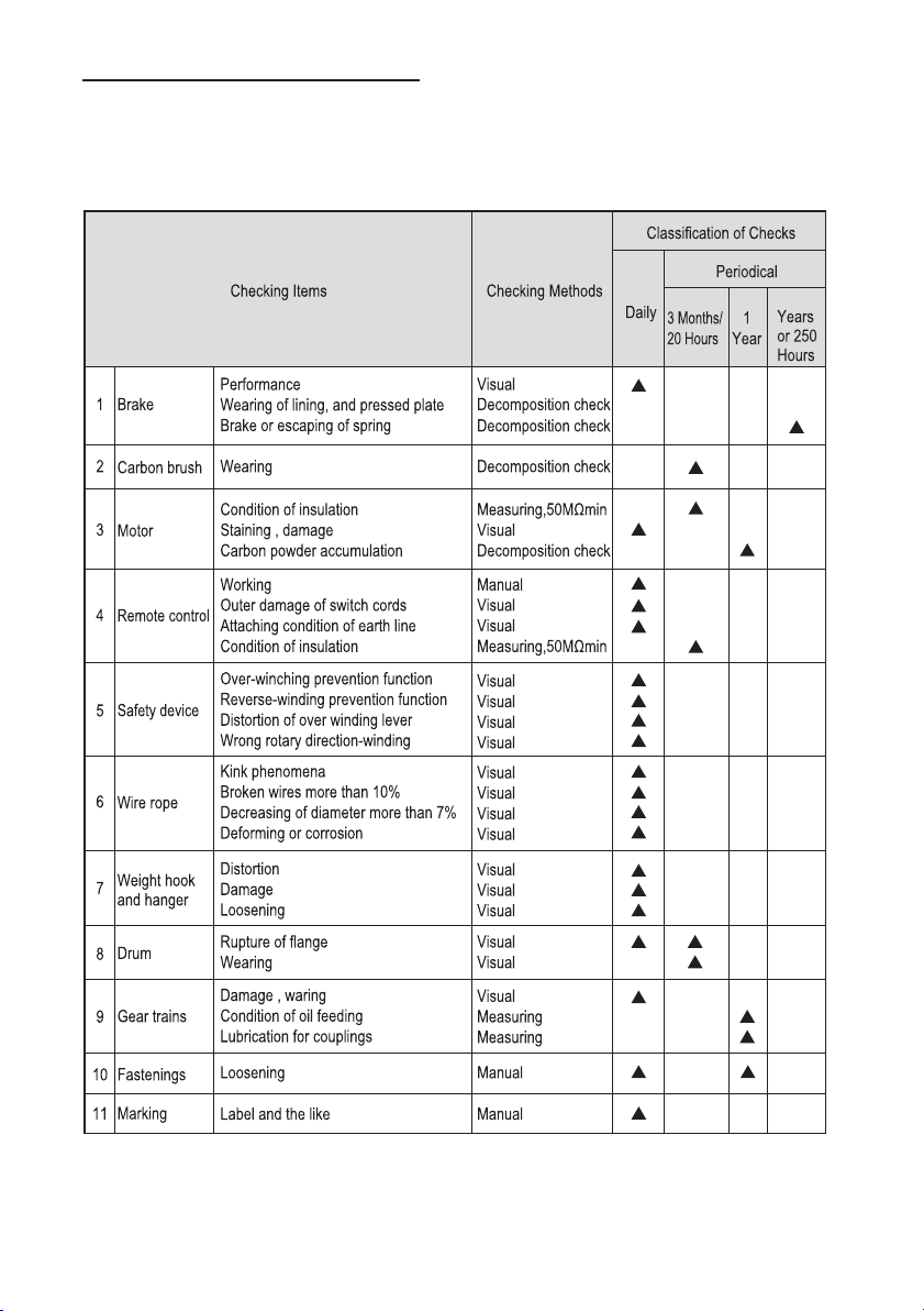
•The specified person performs the checking of winch.
•Divide the checking into daily checking and periodic checking.
•The checking items and checking method in daily and periodic checking
shall be carried out and different according to the using frequency.
9 10
7. Trouble Shootings
6. Checking reference
Fail to hold the
load after
stopping
The gap of ratchet brake is too large Adjust the ratchet brake
Malfunction of pressed spring of ratchet brake Replace pressed spring
The oil is too dirty or includes contamination Replace oil
Having too much oil in gear box Reduce the quantity of oil
Brake distance is
too long at no
load
Malfunction of D type resistor Check or replace D type resistor
Having smell or
smoke
Malfunction of pressed spring of ratchet brake Replace pressed spring
Burnt D type resistor Replace D type resistor
Malfunction of B contact of the pendant switch Replace pendant switch
Too noise whiling
lifting
The noise result from the click between ratchet
stopper and wheel
It is normal
•The specified person performs the checking of winch.
•Divide the checking into daily checking and periodic checking.
•The checking items and checking method in daily and periodic checking
shall be carried out and different according to the using frequency.
9 10
7. Trouble Shootings
6. Checking reference

ELECTRIC MINI WINCH
a
t
i
o
n
z
i
f
n
o
a
r
g
S
r
t
a
O
n
l
d
a
a
n
r
o
i
d
t
i
a
z
a
n
r
t
i
e
o
t
n
n
I
9001
Instruction Manual
Mini Electric Winch
S-series,T-series,M-series
READY THIS MANUAL BEFORE USING THESE PRODUCTS
This manual contains important safety, installation, operation
and maintenance information. Make this manual available
to all persons responsible for the operation, installation and
maintenance of the mini electric winch.