Loading ...
Loading ...

2 | ENGLISH
4. Use a Phillips-head screwdriver to carefully unthread and
remove the screws that connect the telescope’s corrector
retaining ring to the front cell (Figure 5). For 5” through 9.25”
telescopes, there will be six screws to remove. For 11” and 14”
telescopes, there will be eight screws to remove.
5. Carefully remove the retaining ring from the telescope.
Also remove the gasket material ring underneath the plastic
retaining ring.(Figure 5b)
For 8”, 9.25”, and 11” telescopes only, there are two pins on
the interior of the front cell that are for the telescope’s lens cap.
These will interfere with removing the retaining ring. Slightly
bend the plastic ring to provide clearance with one of the pins
so you can remove the ring.
Fig 5
Fig 5b
Retaining Ring
Gasket Ring
7. Reinstall the screws removed previously. Only fi nger tighten
initially. Then, when tightening the screws with your Phillips-head
screwdriver, use a cross pattern among the screws (Figure 7).
Only lightly tighten screws at fi rst, so the head of the screw is just
above the retaining ring. When all screws are lightly installed,
begin fi nal tightening of the screws, again in a cross pattern.
Make sure the screws are fi rmly tightened but do not overtighten
them or you may strip the threads.
Fig 6b
Pin
Notch
Compliance labeling
Dovetail
Fig 6
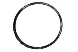
6. Carefully place the dew heater ring where the retaining
ring was previously. Orient the dew heater ring so that the
compliance labeling on the ring is just to the right of the
telescope’s dovetail when looking at the front of the tube
(see Figure 6). Line up the through holes in the dew heater
ring with the threaded holes in the telescope’s front cell.
For 8”, 9.25”, and 11” telescopes only, the pins on the interior
of the front cell will interfere with installation of the of the
aluminum ring, but there is a notch in the ring’s perimeter to
account for this. First, place the outer edge of the ring under
one of the pins. Then, rotate the ring until the notch lines up with
the other pin (Figure 6b), and you can now seat the ring onto
the lens cell. Once seated, rotate the ring until it is oriented as
indicated in Figure 6.
2. Remove the dust cover and any dew shield connected to the
optical tube.
3. Use the included paper installation shield to cover the optics
during dew heater ring installation. This will help protect the
Schmidt corrector lens from inadvertent scratching, fi ngerprints,
and dust. Place the paper shield over the Schmidt corrector
so the secondary obstruction fi ts within the central hole in the
shield (Figure 4).
Fig 4
Loading ...
Loading ...
Loading ...