Loading ...
Loading ...
Loading ...
- 9
Install the attachment set for suction
pipes or the attachment set for storage
tank according to the enclosed assem-
bling instructions.
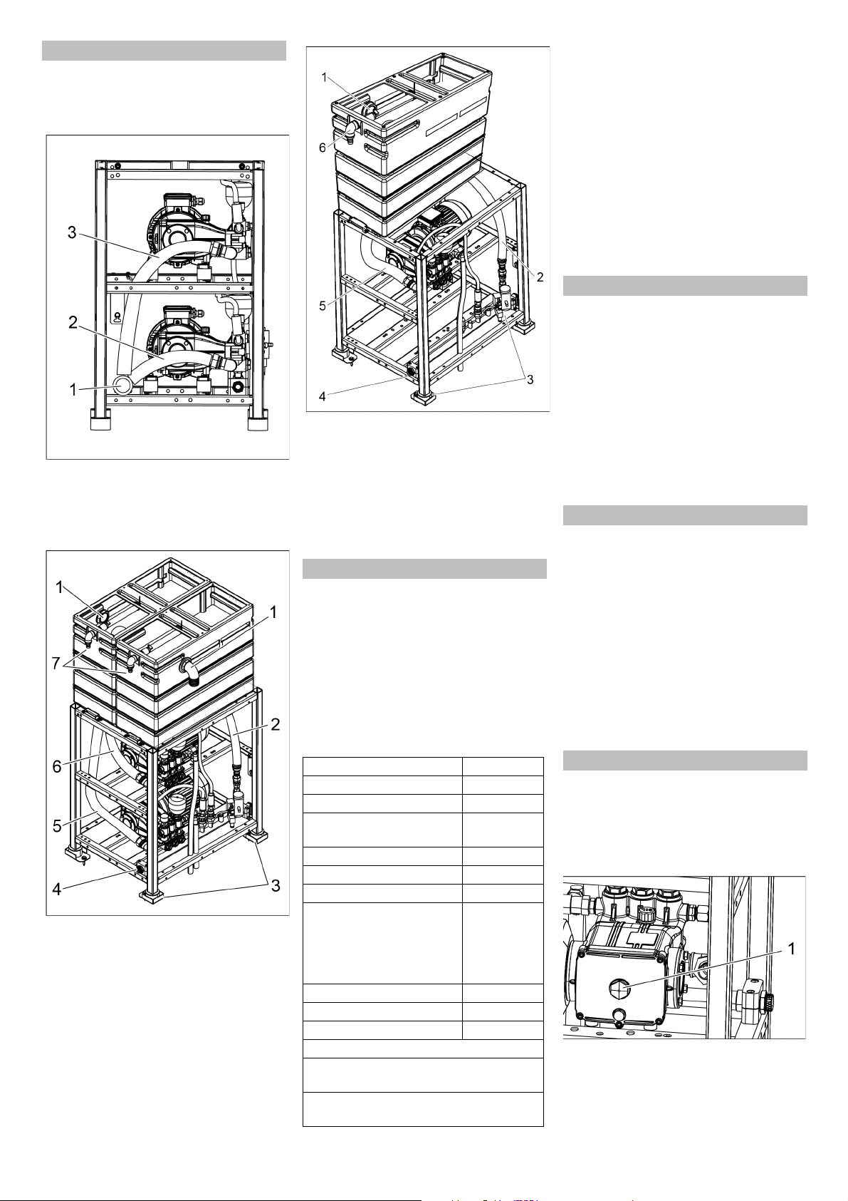
High-pressure module with upgrade kit
suction pipe
1 Water inlet
2 Inlet hose for pump 2
3 Inlet hose for pump 1
HD 60/6 K2, HD 60/10 K2 with attachment
kit for storage tank
1 Overflow storage tank
2 Bypass connection
3 Anti-skid clamp
4 High-pressure outlet
5 Inlet hose for pump 2
6 Inlet hose for pump 1
7 Water inlet
HD 30/6 with attachment kit for storage
tank
1 Overflow storage tank
2 Bypass connection
3 Anti-skid clamp
4 High-pressure outlet
5 Pump supply hose
6 Water inlet
Note:
Impurities in the inlet water can damage the
unit. Kärcher recommends the use of a wa-
ter filter (see "accessories").
While connecting to the drinking water
pipes, please follow the local regulations
about separating the supplies.
ATTENTION
Risk of damage to the plant if water supply
is not of suitable quality.
Quality requirements for tap water:
For connection values refer to technical
specifications.
Connect water inlet to the high pressure
module. For minimum diameter of inlet
pipe refer technical specifications.
Lay the pipe from the bypass valve to
the storage tank.
For ABS storage tank: Lay the pipe
from overflow of the storage tank to the
water drainage.
Provide compressed air to the bypass
valve.
For ABS underbody cleaning: Provide
compressed air to the high pressure
distributor.
– Establish the connection between the
fixed pipes and the high pressure mod-
ule as a high pressure hose connection.
– Lay the fixed pipes as straight as possi-
ble.
– Fasten pipes with dampened flexible
(loose and tight) clips on account of
changes in length due to effects of pres-
sure and temperature.
– Nominal pipe diamter minimum 25 mm/
1 inch.
– Nominal diameter of hose pipes mini-
mum 20 mm.
DANGER
Risk of electrical voltage! All electrical in-
stallations may only be done by an electri-
cian according to the local regulations.
The mains must be connected by an expe-
rienced technician and the requirements of
the IEC 60664-1 must be fulfilled.
The pump module may only be connected
to a electricity source with proper earthing.
All current-conducting parts in the working
area must be protected against jet water.
Connect power supply and control
wires in the switching cabinet according
to the circuit plan.
Rinse the firmly installed pipe at the in-
stallation site.
Check that all high pressure pipes are
assembled correctly and are not leaky.
Check that water inlet has the required
flow and the permissible temperature.
1 Oil level indicator
Check oil level in both the pumps. The
oil level must be at the centre of the oil
level display.
Assemble the installation parts
Water connection
pH value 6,5...9,5
electrical conductivity < 2000 µS/cm
removable materials * < 0,5 mg/l
filterable materials (grain
size below 0.025 mm)
< 20 mg/l
Hydrocarbons < 20 mg/l
Chloride < 300 mg/l
Calcium ** < 85 mg/l
Total hardness < 15 °dH
< 26,7 °fH
< 18,75 °eH
< 267 ppm
< 15,6 gr/gal
Iron < 0,5 mg/l
Manganese < 0,05 mg/l
Copper < 0,02 mg/l
free of bad odours
* Test volume 1litre, Settling time 30 min-
utes
** decalcification measures are necessary
if the values are higher
High pressure connection
Electrical connection
Initial Start-Up
21EN
Loading ...
Loading ...
Loading ...