Loading ...
Loading ...
Loading ...
Y
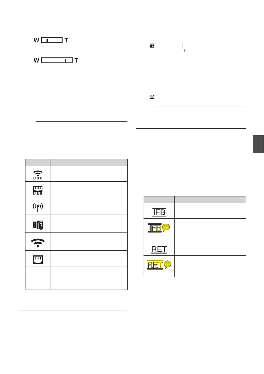
Zoom Display
0
Displays the zoom position. (Zoom bar or
value)
Dynamic Zoom Off:
.
Dynamic Zoom On:
.
0
The zoom bar will only be displayed for 3
seconds after the zoom operation is
activated.
0
The value will always be displayed.
Dynamic Zoom Off: Z00 to Z99
Dynamic Zoom On: DZ000 to DZ149
0
When [Digital Extender] is configured to “On”,
“F” is displayed to the right of the zoom
display.
Memo :
0
The mode of display (value or bar) can be
configured in [LCD/VF] B [Display Type] B
[Zoom].
Z
Network Connection Icon
The network connection status is displayed.
Icon Status
.
Wireless LAN connection from the
host terminal (USB) is established
.
Wired LAN connection from the
host terminal (USB) is established
.
Cellular adapter connection from
the host terminal (USB) is
established
.
When a USB adapter different
from the connection settings is
detected
.
Built-in wireless LAN connection is
established
A
.
LAN terminal connection is
established
(No
display)
0
When an unusable USB
adapter is detected
0
When the LAN cable is not
connected
Memo :
0
Yellow display indicates preparation for
connection in progress.
a
Time Code (I)/User’s Bit (J) Display
0
Displays the time code (hour: minute:
second: frame) or user’s bit data.
0
Example of time code display:
Display Screen
.
00:00:00:00
*
* Colon (:) denotes non-drop frames and dot
(.) denotes drop frames.
0
Example of user’s bit display:
Display Screen
.
FF EE DD 20
Memo :
0
Use [LCD/VF] B [Display Type
] B [TC/UB] to
toggle between the time code display and user’s
bit display.
b
Time Code Lock Indicator
0
When the built-in time code generator is
synchronized to the external time code data
input during the synchronization of time code
with another camera recorder, Z lights up.
0
Z lights up when [TC/UB] B [TC Generator]
is configured to “Free Run(NTP)” and the unit
has detected and synchronized to the NTP
server.
c
IFB/RET Mark
Displays the status of the IFB or Return over IP.
Icon Status
.
During audio feed only
.
(Yellow)
When an error occurs during
audio feed only
.
During video+audio feed
.
(Yellow)
When an error occurs during
video+audio feed
Display Screen in Camera Mode
169
Display/Status Screen
Loading ...
Loading ...
Loading ...