Loading ...
Loading ...
Loading ...

- 2
The safety valve opens when the admissi-
ble operating pressure is exceeded.
DANGER
Immediate danger that can cause severe
injury or even death.
몇 WARNING
Possible hazardous situation that could
lead to severe injury or even death.
CAUTION
Possible hazardous situation that could
lead to mild injury to persons or damage to
property.
– When the pistol trigger is pressed, com-
pressed air flows through the air nozzle.
– The negative pressure that is generat-
ed by the injector sucks the spray agent
out of the open spray agent container
through the spray agent hose and the
suction pipe.
– The spray agent is accelerated and out-
put by the air blast in the jet nozzle.
– The spraying agent volume can be con-
tinuously adjusted to the cleaning task
by means of the spray agent control.
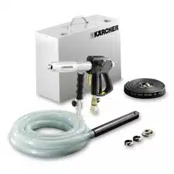
Your sales outlet should be informed about
any transit damage noted when unpacking
the product.
Secure the spray agent hose by means
of the hose clips.
Connect the air hose to the compressor
by means of the hose coupling.
Ensure that the couplings are seated
properly.
For connection values refer to technical
specifications.
A water filter inside the inlet prevents faults.
몇 WARNING
Observe regulations of water supplier.
According to the applicable regula-
tions, the appliance must never be
used on the drinking water supply
without a system separator. Use a
suitable system separator manufactured by
KÄRCHER; or, as an alternative, a system
separator as per EN 12729 Type BA. Water
flowing through a system separator is con-
sidered non-drinkable.
-CAUTION
Always connect the system separator to
the water supply, never directly to the appli-
ance!
Connect the water inlet hose (not in-
cluded in the delivery) with the appli-
ance and the water supply.
The jet performance depends on the size of
the compressor used.
The following table shows the correlation
between the air quantity and the attainable
jet pressure.
The operating pressure is continuously ad-
justed by means of the air volume control
button.
The maximum admissible operating pres-
sure is 1.2 MPa (12 bar).
Push the suction pipe in the spray me-
dium and ensure that the air inlets are
not covered.
Maximum spray medium suction height: 4 m.
Switch on compressor.
Open the water supply.
Unlock trigger safety.
Pull the pistol trigger and perform clean-
ing task.
In order to avoid the formation of dust, wa-
ter can be added to the mixture of spray
agent and air.
Set selection switch water to ON.
Adjust the quantity of water at the water
quantity regulator.
Note:
The water supply is only active when the
pistol trigger is pulled.
For the binding of dust only a small quantity
of water (maximum 20 l/h) is required.
Close the spray quantity control.
Open the water volume regulation.
Pull pistol trigger.
After operation:
Set selection switch water to OFF.
Pull the pistol trigger and blow residual
water out of the pistol.
Release pistol trigger.
Lock pistol trigger by means of the trig-
ger safety to avoid accidental opera-
tion.
Thoroughly wash hands after finishing
spraying tasks.
몇 WARNING
Risk of injury. Close compressed air sup-
ply, depressurize and disconnect the appli-
ance from the compressed air supply prior
to performing work on the appliance.
Note:
Mixing chamber and air nozzle are wear
parts and are not subject to the warranty
provisions.
You can sign with your dealer a contract for
regular safety inspection or even sign a
maintenance contract. Please take advice
on this matter.
Check the hose connections for tight
seating
Check spray agent hose for wear and
tear.
Check compressed air hose for wear
and tear.
Check the spray nozzle for wear.
The jet performance is significantly re-
duced with a worn spray nozzle.
Check mixing chamber for wear and re-
place if severely worn.
Dismantle mixing chamber and check
air nozzle for wear.
1 Part to be screwed
2 Screw
3 Stream nozzle
4 Air nozzle
5 Mixing chamber
6 Add-on components mixing chamber
Dismantle add-on components of the
mixing chamber.
Loosen the screws.
Remove the mixing chamber from the
screw connection and spray nozzle.
Safety Devices
Symbols in the operating instruc-
tions
Function
Start up
Attaching the Accessories
Compressed air connection
Water connection
Operations
Jet performance
Air
quanti-
ty [m
3
/
min]
Pres-
sure
[MPa
(bar)]
Air
quanti-
ty [m
3
/
min]
Pres-
sure
[MPa
(bar)]
2,4 0,3 (3) 5,4 0,8 (8)
3,0 0,4 (4) 6,1 0,9 (9)
3,6 0,5 (5) 6,7 1,0 (10)
4,2 0,6 (6) 7,3 1,1 (11)
4,8 0,7 (7) 8,0 1,2 (12)
Operating pressure
Spray medium suction
Operation
Operation with water
Rinse spray medium residues
Shutting down
Care and maintenance
Safety inspection/ maintenance
contract
Daily
Weekly
Monthly
Replace mixing chamber and air
nozzle
8 EN
Loading ...
Loading ...
Loading ...