Loading ...
Loading ...
Loading ...
7
805757 v1.05 06.21 Miniboil Install Instructions
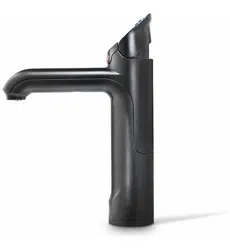
Flow Direction
Pressure
Limiting
Valve
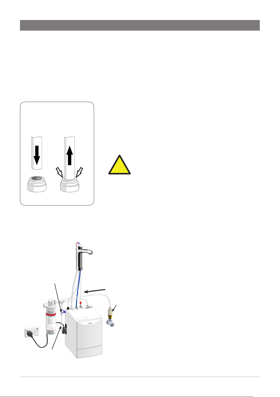
Fig. 2 External Filter Connection
Flush Tube
Flush Valve
Installation
Step B - Installing the filter
Miniboil is supplied with an external filter (see diagram below). It is
important the filter be securely fixed adjacent to the under sink unit in
such a manner as to allow for easy access to the filter, for service and
regular replacement.
The ¼” LDPE tube supplied must be carefully measured and cut to
allow for the connection of the filter, double check valve and JG
fittings.
Step C - Installing the Command Centre
Position the Command Centre as close as possible to the tap.
The connection tubes supplied with the tap assembly CANNOT be
lengthened.
Allow at least a 50 mm air-gap to the RHS for air circulation.
Allow a 70 mm clearance on the LHS of the appliance to ensure the
power lead is free from external force.
IMPORTANT: Proper air circulation and adequate
cupboard ventilation is necessary for efficient
operation.
Adjust cupboard door hinges and attach the supplied silicone
door buffers to create a 4 mm air-gap between the doors and the
cupboard. This is the minimum ventilation requirement for low
usage installations. Failure to do this may cause the appliance to
overheat and operate inefficiently.
Step D - Connecting the water supply
To prevent sediment from the in-wall plumbing entering the
Command Centre at connection, flush water through the supply line
thoroughly before connection.
!
Filter assembly sequence: (see Fig 2)
Fit the pressure limiting valve to the outlet side of the
isolating valve (not supplied).
Mount the filter and flush valve assemblies in a convenient
position using the angle bracket supplied.
Connect the filter assembly plumbing between the
pressure limiting valve and the inlet of the Command
Centre using the ¼” JG fittings supplied (see Fig 1). Take
note of the flow direction, marked with an arrow on the top
of the filter head.
Ensure the flush valve is accessible after installation as this
will be required to flush water through the filter, when the
filter is installed or changed.
Fig 1. John Guest (JG)
fittings - Assembly and
Removal
Loading ...
Loading ...
Loading ...