1
805757 v1.05 06.21 Miniboil Install Instructions
Installation instructions & user manual
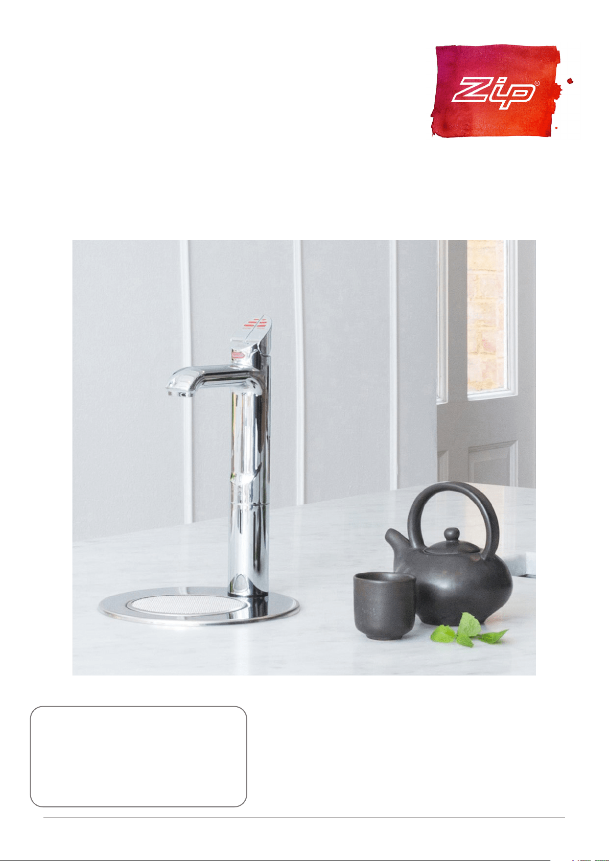
Zip Miniboil
AFFIX PRODUCT LABEL HERE
805757
Models: Boiling/Ambient, Boiling Only

2 805757 v1.05 06.21 Miniboil Install Instructions
Before Installation:
A. Read the instructions.
B. Note: Not all fittings are supplied with the appliance kit. Isolation valves are not
supplied.
C. The pressure limiting valve must be fitted as part of the kit.
D. Check the water quality to determine if extra filtration will be required.
E. Check the appliance rating plate and ensure correct power is available for the
appliance.
F. Check the underbench cupboard supporting the appliance is adequate for
the total weight of the appliance, when full of water.
Before Commissioning:
1. Check the unit has been secured correctly.
2. Flush the supply line before connecting.
3. Check all plumbing fittings have been tightened.
4. Ensure the outlet and vent pipes are positioned to drain correctly.
5. For command centres ensure there is adequate ventilation.
6. Check all tubes from the Command Centre to the tap, have a constant rise and
there are no ‘S’ traps or kinks in the hoses.
7. Check all electrical connections are correct and there are no loose wires.
Commission:
8. Turn on the water and check for leaks.
9. Turn on the power.
10. Flush 7 - 10 litres of water through the filter.
11. Allow sufficient time for the unit to heat up, before using.
Checklist

3
805757 v1.05 06.21 Miniboil Install Instructions
Contents
Contents
WARNINGS AND PRECAUTIONS .....................................4
Technical specification .................................................. 5
Installation requirements .............................................. 5
Special tools required .................................................... 6
Installation .................................................................... 6
Step A - Installing the tap ..................................................6
Step B - Installing the filter ................................................ 7
Step C - Installing the Command Centre .......................... 7
Step D - Connecting the water supply .............................. 7
Step E - Connecting the tap .............................................. 8
Step F - Testing and commissioning .................................8
Operation ......................................................................9
Font installation .......................................................... 10
Cleaning ....................................................................... 11
End of Life Disposal ...................................................... 11
4 805757 v1.05 06.21 Miniboil Install Instructions
WARNINGS AND PRECAUTIONS
!
For continued safety of this appliance it must be installed, operated
and maintained in accordance with the manufacturer’s instructions.
This appliance may deliver water at high temperature. Refer to the
Plumbing Code of Australia (PCA), local requirements and installation
instructions to determine if additional delivery temperature control is
required.
• All plumbing must comply with AS3500.4.1 & AS3500.4.2
• All electrical must comply with AS3300 wiring rules
Safety
This appliance is not intended for use by persons (including children)
with reduced physical, sensory or mental capabilities, or lack of
experience and knowledge, unless they have been given supervision
or instruction concerning use of the appliance by a person responsible
for their safety. Children should be supervised to ensure they do not
play with the appliance
Qualifications
If any power cord or plug is damaged it must be repaired only by a
qualified technician. To avoid hazards, all installation procedures
must be carried out by a suitably qualified trades person. The power
cord and general power outlet must be in a safe visible position for
connection.
Venting
Sometimes steam and / or boiling water may discharge through a vent
outlet at the mouth of the tap. If the tap is not installed using the Font
pedestal, ensure the tap body is located so the tap outlet safely drains
into the sink bowl area.
Lifting
Take care when lifting the Command Centre. Some units may
exceed safe lifting limits. Do not lift without assistance. The weights
of the units are given in the table under the heading “Installation
Requirements”.
Airflow
The ambient temperatures this unit should operate within are 5ºC
- 35ºC. The system will operate satisfactorily only if the recommended
air gaps are provided, as noted in the installation procedure.
Intended use
This appliance is intended to be used in household and similar
applications such as: staff kitchen areas in shops, offices and other
working environments; by clients in hotels, motels and other
residential-type environments; catering and similar non-retail
applications.
Frost protection
If this appliance is located where the ambient air temperature could
fall below 5ºC, do not turn off the appliance electrically. This safeguard
does not offer the same protection to the connecting pipework and
fittings.
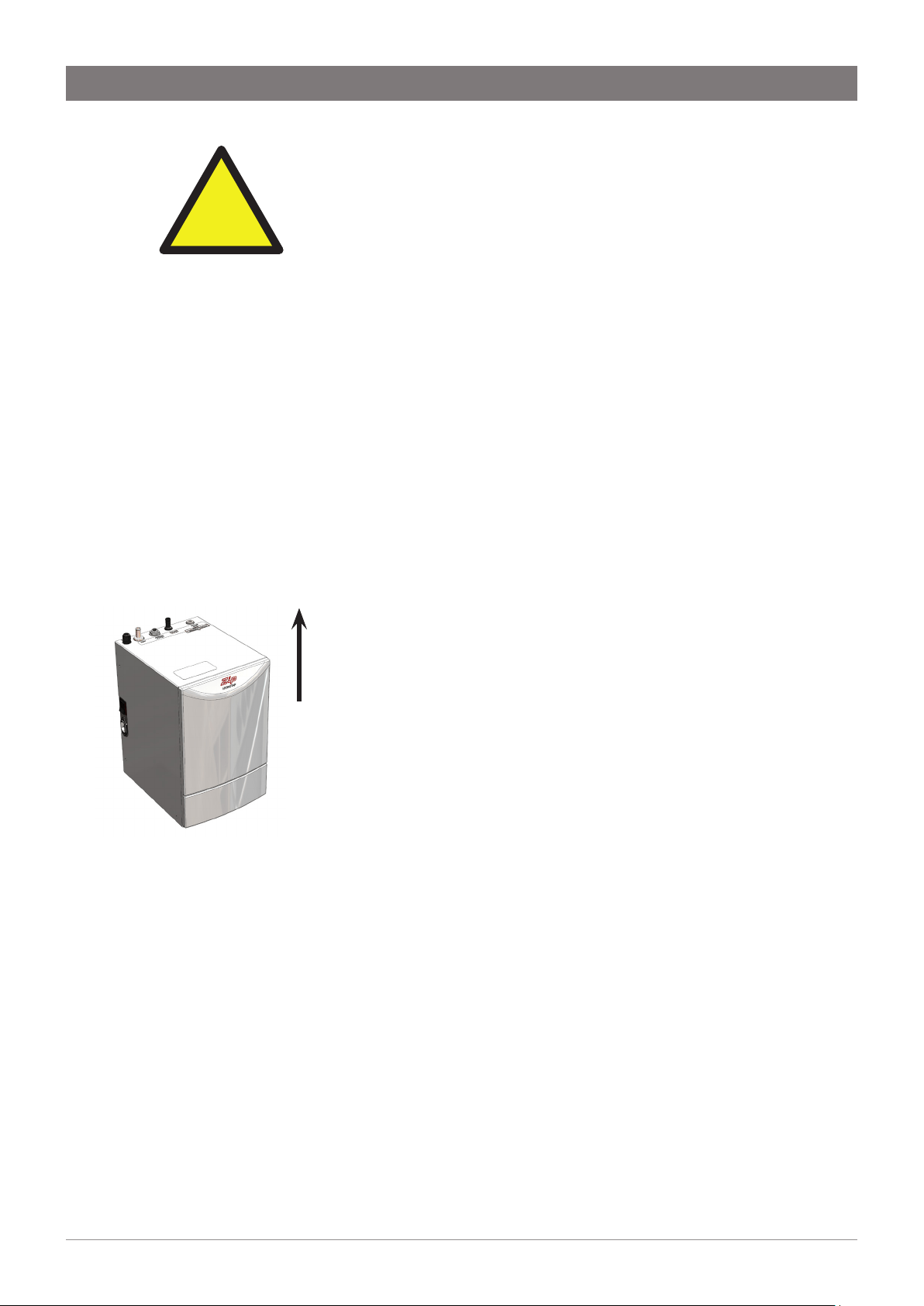
The power point must be
located within reach of its
cable. The appliance must be
positioned so that the plug is
accessible.
Zip Miniboil Command
Centre.
The appliance must be
placed on a horizontal
surface in an upright
position, as shown above.
This way up
5
805757 v1.05 06.21 Miniboil Install Instructions
WARNINGS AND PRECAUTIONS
!
Installation environment considerations
This unit is intended for indoor use only and should never be installed
outdoors or exposed to the elements of nature. This unit must not be
positioned in an area that may be cleaned by a water jet. This unit must
not be cleaned by a water jet.
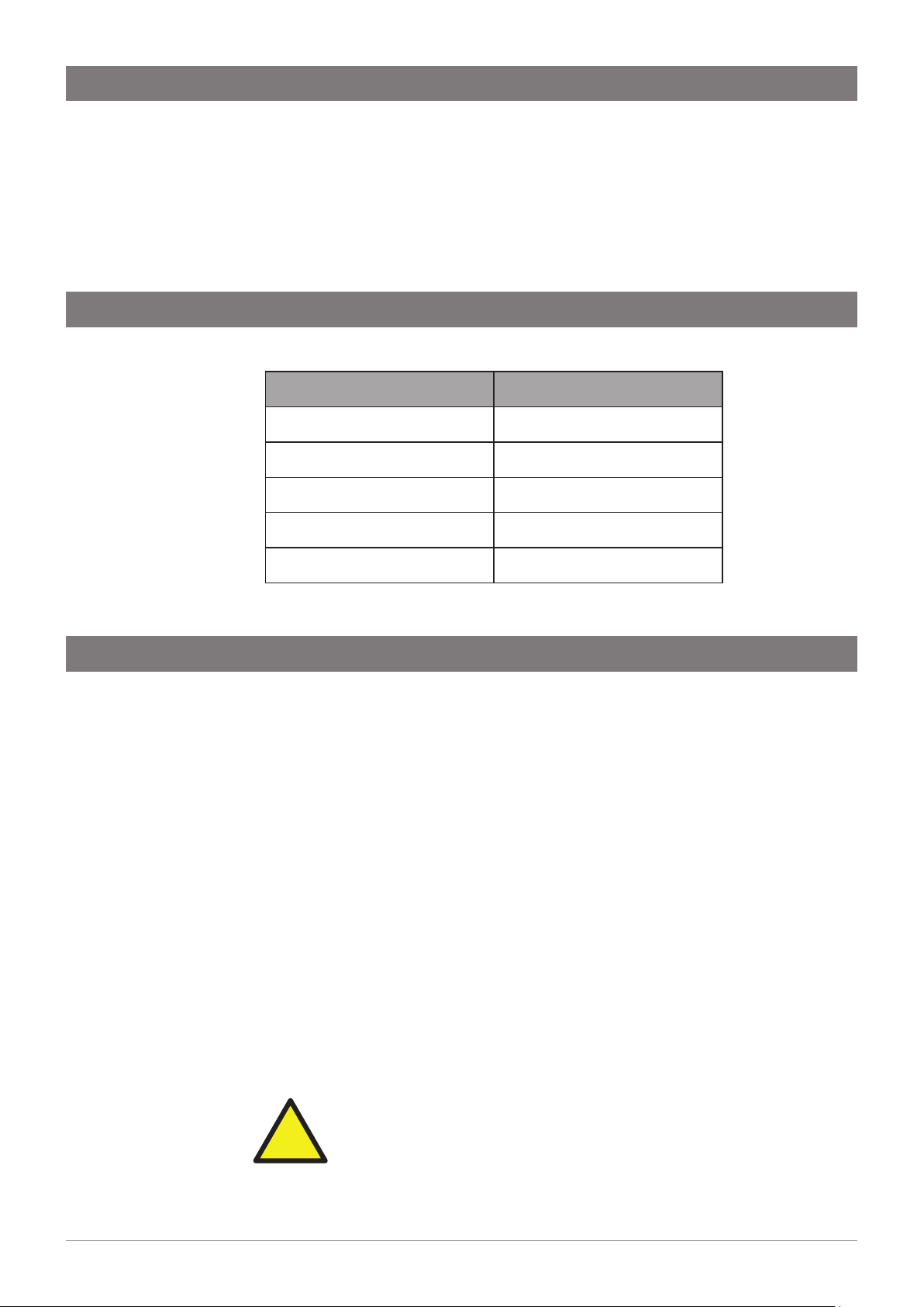
Technical specification
Installation requirements
MODEL Miniboil BA, Miniboil BO
Capacity 1.8 Litres
Power rating 1500 Watts
Width x Depth x Height (mm) 212 x 269 x 338
Weight (dry) 6.5 kg
Weight (full) 8.3 kg
Before installing ensure that the following have been provided at the
installation site:
• Sufficient space in the cupboard to install the command centre
in accordance with these Installation Instructions.
NOTE: Allow clearance of 50 mm around all sides and 200mm
above the command centre for air circulation.
• A water supply connection with isolating valve inside the
cupboard within reach of the 750 mm flexible connection and
positioned so that the connection point and the stop cock will
not be obstructed when the command centre is installed.
• Power supply 220-240 Volt AC, for connection to the appliance
via a 10 amp G.P.O.
• Cold water supply with a minimum working pressure of 150 kPa
and a maximum working pressure of 700 kPa connected via an
isolation valve.
• A 350kPa pressure limiting valve/DNR is supplied with the filter
kit and must be installed.
IMPORTANT! Do not proceed with the installation if these
requirements are not met.
6 805757 v1.05 06.21 Miniboil Install Instructions
In addition to normal tools, the following will be required:
• 35mm diameter sheet metal hole punch for sink tops (not
supplied)
• 35mm diameter hole saw for timber bench tops (not supplied)
• Nut runner tube spanner (supplied) for fixing tap assembly.
Special tools required
Installation
Step A - Installing the tap
The vertical distance between the base of the Tap
assembly and the top of the Command Centre must be
BETWEEN 400 - 900mm. Failure to install within these
parameters may result in poor water delivery.
1. Make sure that the tap location will allow the nozzle to drain into
the sink.
2. Cut a 35mm hole in the bench / sink top.
3. Install the black plastic spacer to the base of the tap and ensure
it remains in place as this is the moisture seal against the bench /
sink top. A light smearing of silicon sealant on the underside of the
spacer will ensure a watertight fit.
4. Pass the hoses through the 35mm hole and carefully locate the
Head Assembly and black spacer on the bench / sink area.
5. From the underside of the bench / sink area re-locate the S/S
washer and “Spider Clamp” by feeding each of the tubes and
electrical cable evenly in between the legs of the “Spider Clamp”.
Slide it up to meet the “All Thread”, and pass the “All Thread”
through the centre of the “Spider Clamp”.
6. Hold the “All Thread” steady and re-fit the 6mm nut to the “All
Thread” using the tube spanner supplied in the kit. Check the Tap
Head position before securing it tightly against the bench / sink
top.
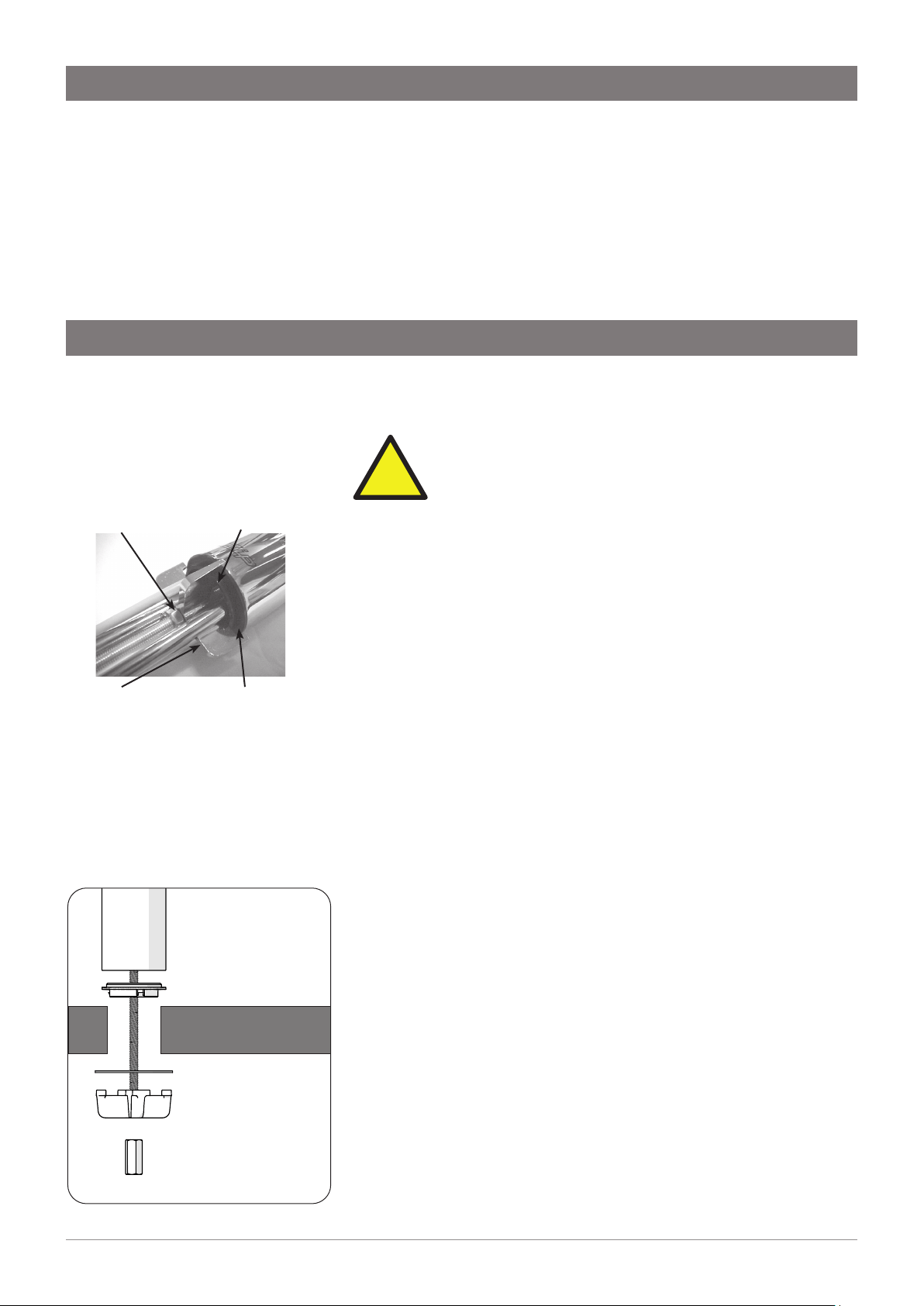
Under no circumstances should the Tap be twisted after the
installation is complete.
Fixing nut Black spacer
Smear silicon on
underside of flat
surface
Tap
all-thread rod
black plastic spacer
benchtop
s/s washer
spider clamp
fixing nut
Spider
clamp
!
7
805757 v1.05 06.21 Miniboil Install Instructions
Flow Direction
Pressure
Limiting
Valve
Fig. 2 External Filter Connection
Flush Tube
Flush Valve
Installation
Step B - Installing the filter
Miniboil is supplied with an external filter (see diagram below). It is
important the filter be securely fixed adjacent to the under sink unit in
such a manner as to allow for easy access to the filter, for service and
regular replacement.
The ¼” LDPE tube supplied must be carefully measured and cut to
allow for the connection of the filter, double check valve and JG
fittings.
Step C - Installing the Command Centre
Position the Command Centre as close as possible to the tap.
The connection tubes supplied with the tap assembly CANNOT be
lengthened.
Allow at least a 50 mm air-gap to the RHS for air circulation.
Allow a 70 mm clearance on the LHS of the appliance to ensure the
power lead is free from external force.
IMPORTANT: Proper air circulation and adequate
cupboard ventilation is necessary for efficient
operation.
Adjust cupboard door hinges and attach the supplied silicone
door buffers to create a 4 mm air-gap between the doors and the
cupboard. This is the minimum ventilation requirement for low
usage installations. Failure to do this may cause the appliance to
overheat and operate inefficiently.
Step D - Connecting the water supply
To prevent sediment from the in-wall plumbing entering the
Command Centre at connection, flush water through the supply line
thoroughly before connection.
!
Filter assembly sequence: (see Fig 2)
Fit the pressure limiting valve to the outlet side of the
isolating valve (not supplied).
Mount the filter and flush valve assemblies in a convenient
position using the angle bracket supplied.
Connect the filter assembly plumbing between the
pressure limiting valve and the inlet of the Command
Centre using the ¼” JG fittings supplied (see Fig 1). Take
note of the flow direction, marked with an arrow on the top
of the filter head.
Ensure the flush valve is accessible after installation as this
will be required to flush water through the filter, when the
filter is installed or changed.
Fig 1. John Guest (JG)
fittings - Assembly and
Removal
8 805757 v1.05 06.21 Miniboil Install Instructions
Installation
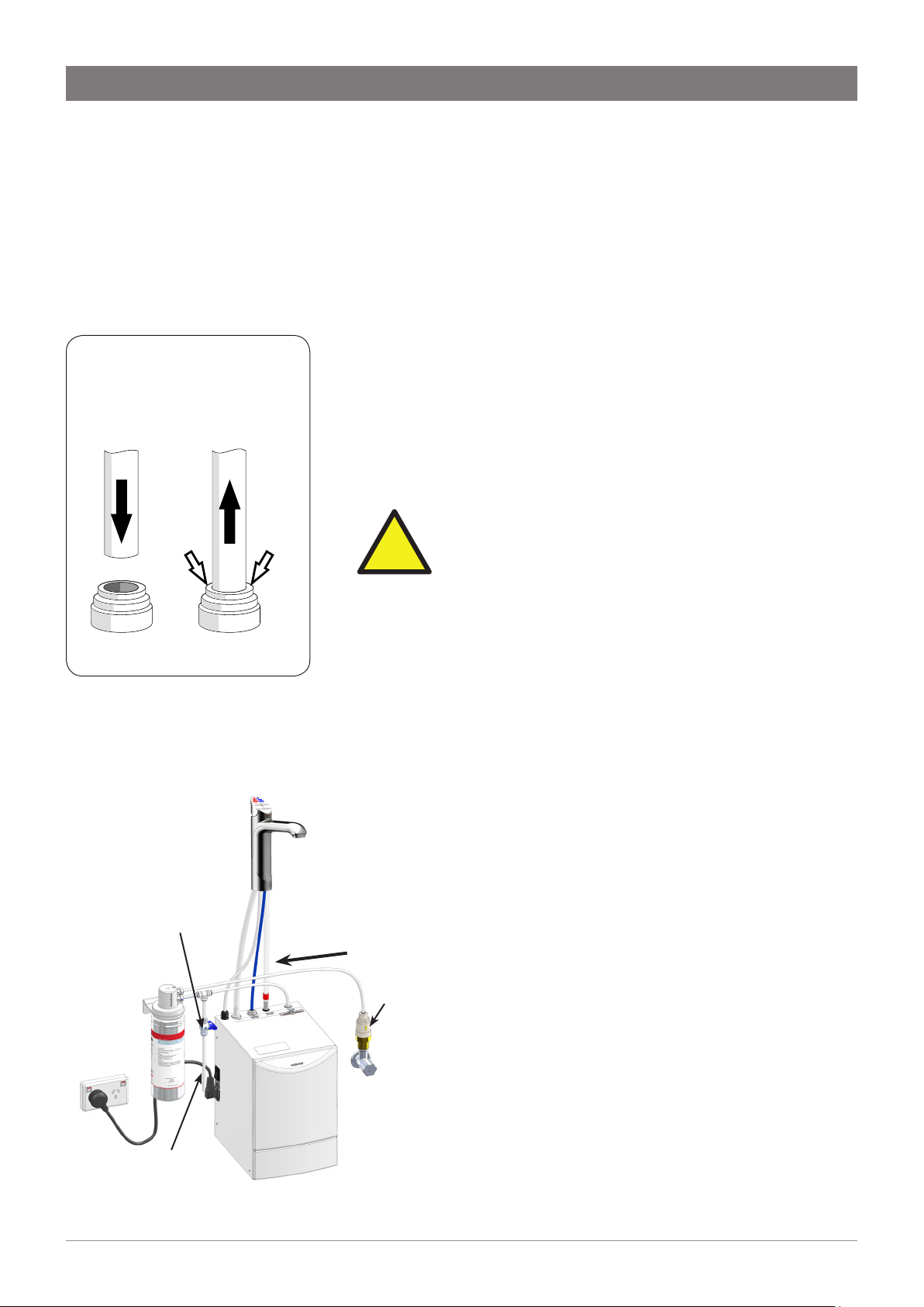
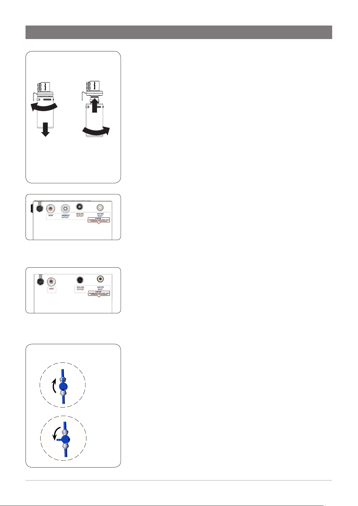
Filter insertion and replacement (Fig 3)
Align the tabs of the cartridge with the filter housing and insert it up
into the socket.
Turn the cartridge a quarter turn to the right until it locks into position.
Reverse this procedure for removal.
Step E - Connecting the tap
• Trim excess silicone tubes to ensure a continuous fall back to
the Command Centre.
• New hose sets supplied with the unit should be used. Do not
use old hose sets.
• Do not loop or allow sagging or kinking of the tubes, to
prevent water from being trapped inside.
• When connecting, slide the tube over the pipe at least 15mm.
Measure and trim the Red silicone tube and connect it to the BOILING
outlet located on the top of the Command Centre.
Measure and trim the CLEAR silicone tube and connect it to the vent
outlet located on the top of the Command Centre.
For Boiling Ambient models, measure and trim the blue LDPE tube and
connect it to the AMBIENT outlet located on the top of the Command
Centre (see Fig 4).
Connect the tap USB connector to the USB lead on the Command
Centre. It should be fitted together tightly until a "click" is felt. Failure to
fully insert the connector will prevent tap operation. Once connected,
fix the cable to the wall, ensuring it is off the floor and away from any
possible water splashes.
Turn on water and check for leaks.
Step F - Testing and commissioning
The appliance is now running in normal operating mode. The Red LED
will flash until factory set temperature is reached.
Filter flush
When commissioning, it is advisable to flush the filter for several
minutes to remove any fine filter particles. Use a bucket to collect and
dispose of the waste water.
To flush the filter, first turn on the water supply and then turn on the
flush valve (see Fig 6.). Discharge approximately 7.5L of water into the
bucket.
Once the filter has been flushed, turn the flush valve off.
Wait 5 minutes after this point to allow adequate fill time.
The unit is now ready for use. Test water delivery from the tap and
check for appropriate temperatures. Use cable clips to tidy and secure
wiring.
ON
OFF
Fig 6. Flush Valve
Open
position
Closed
position
Fig 3. Cartridge replacement
Cartridge
Removal
Cartridge
Insertion
ROTATE
PULL
DOWN
1
2
1
2
ROTATE
INSERT
Fig 5. Boiling Only model:
Connection viewed from the top
Fig 4.Boiling/Ambient models:
Connection viewed from the top
9
805757 v1.05 06.21 Miniboil Install Instructions
Operation
Note: If the appliance has not been used for several days, allow the tap to
run ambient water for about one minute.
Tap Operation
Press the RED lever and the SAFETY button to dispense boiling water.
Pull the RED lever up while holding the SAFETY button to dispense boiling water
continually. The water will flow for about 15 seconds. Then manually return the
lever to the off position.
Press the BLUE lever to dispense cold (ambient) water. Pull the lever up to
dispense ambient water continually. The water will flow for about 15 seconds.
Then manually return the lever to the off position.
Tap Lights
Red LED: Boiling water
• Steady light: boiling water is ready and can be dispensed.
• Flashing: the water temperature is below the set value. Boiling water
cannot be dispensed.
• Flashing slowly: the unit is in Sleep mode.
Blue LED: Cold (ambient) water (for BA model only)
• Steady light: ambient-temperature water can be dispensed.
All LEDs: Fault
• Flashing: there is a fault in the unit. In that case, switch off the unit for
at least 20 seconds. If the fault has not been corrected when the unit is
switched on again, contact customer service.
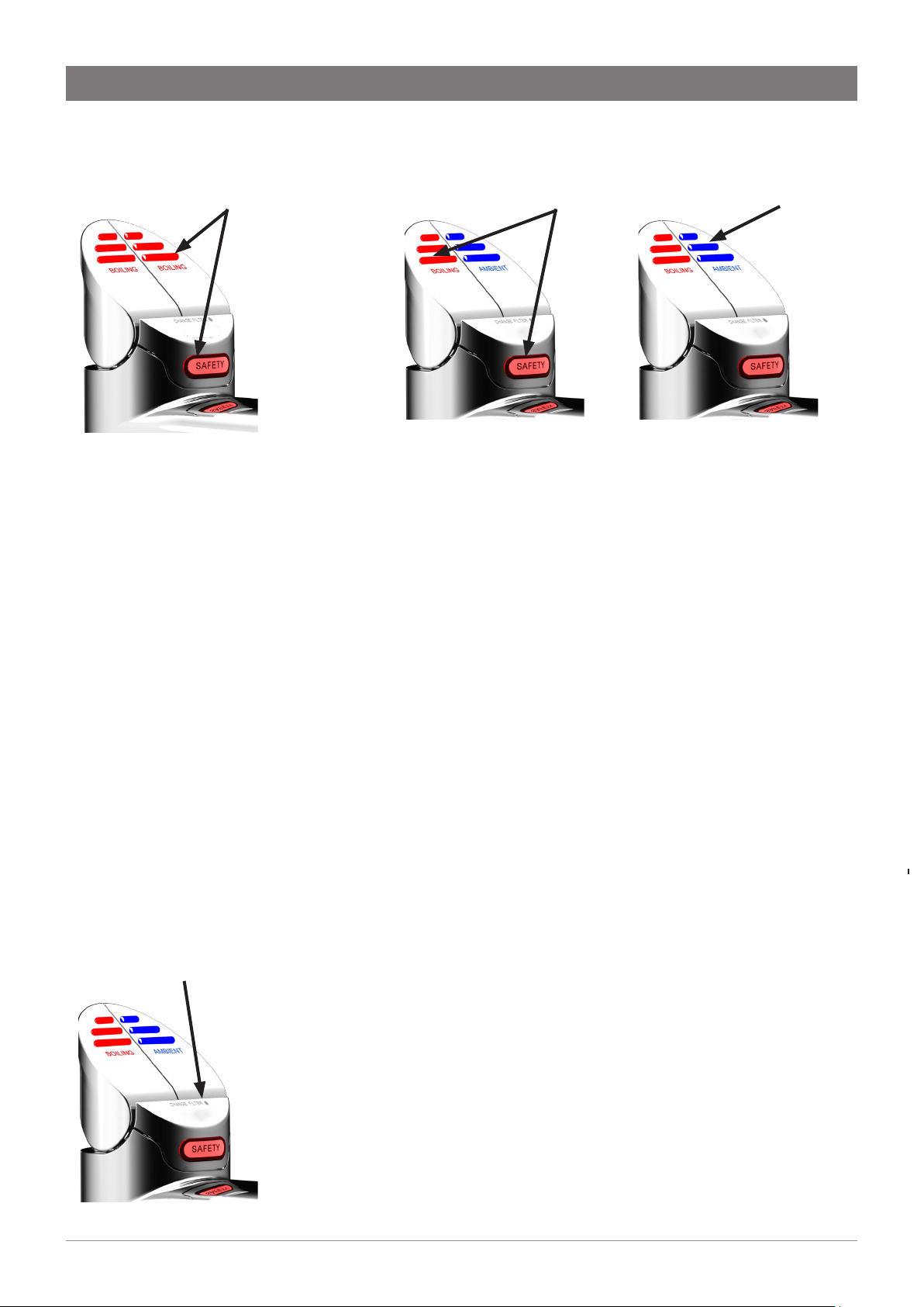
Change Filter light
• Off: Indicates the water filter is operating within its normal specified
lifespan.
• Flashing slowly: Indicates the water filter is due for replacement, after 12
months of use or after dispensing 4000 litres, whichever occurs first. To
replace the filter, refer to Fig 3. After the filter is changed, it should be
flushed. Refer to Filter flush on previous page.
• Reset filter counters: After filter is changed, hold down BOTH LEVERS for
10 seconds. The Filter Change light will turn ON, and after 10 seconds will
turn OFF. This will reset the filter counters to zero.
Boiling water (BA model):
Press or pull the red lever,
and cover the Safety button
at the same time.
Boiling water will be
dispensed.
Change Filter light
Boiling Only model:
Press or pull either red
lever, and cover the Safety
button at the same time.
Boiling water will be
dispensed.
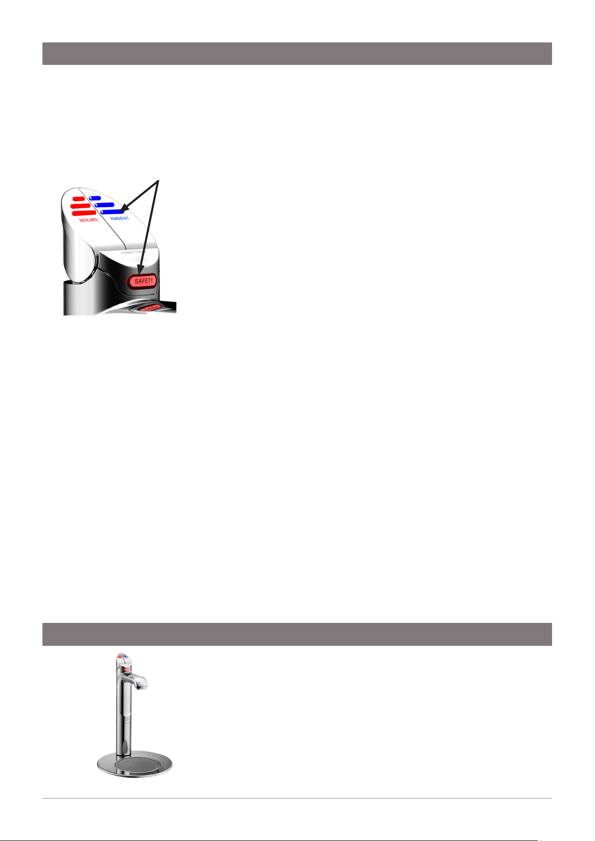
Cold (ambient) water
(BA model):
Press or pull the blue lever.
Cold water will be
dispensed.
10 805757 v1.05 06.21 Miniboil Install Instructions
Sleep mode (for BA model only)
The unit can be set to Sleep mode to save energy. If Sleep mode is
enabled, the unit will switch to Sleep if it has not been used for two
hours. The water temperature will be maintained at 64 °C. Operation
of the tap during this time will wake the system from sleep and the
water will start heating up again. Boiling water is available as soon as
the red LED shows a steady light.
Press the BLUE lever and the SAFETY button and hold them for about 5
seconds to enable or disable Sleep mode.
The red LED and the white LED will flash simultaneously to confirm
that Sleep is enabled. They will flash alternately to confirm that Sleep is
disabled.
Long period of non-use
Note: In ambient / warm water, microorganisms can multiply
faster. It is recommended to leave your drinking water system
switched on even during long periods of non-use.
If you still want to shut down your drinking water system for an
extended period of time, proceed as follows:
1. Turn off the water supply.
2. Use the tap to dispense ambient and hot water until no more water
flows to empty the system.
3. Disconnect the appliance from the power supply.
After prolonged non-use
1. Reconnect the water supply. Pay attention to any leaks.
2. Reconnect the appliance to the power supply.
3. After non-use of several days: Drain at least four litres of ambient
water from the fitting. If necessary collect the water in a suitable
container. As soon as the LED in red lever lights up continuously,
drain hot water. Repeat this process until the LED flashes again.
CAUTION! Hot water will be dispensed.
4. The appliance is now ready for use.
Operation
A font kit is available for this product, sold separately as an accessory.
For details of the available font kits, please contact your Zip customer
service provider. The font installation instructions and mounting
template are supplied with the font kit.
Part No. 90915Z00: Font Kit, Chrome
Font installation
Activate / deactivate sleep mode
(BA model):
Press the blue lever and the Safety
button and hold them for about
five seconds.
LEDs light up simultaneously when
sleep mode is activated.
LEDs light up alternating when
sleep mode is deactivated.
11
805757 v1.05 06.21 Miniboil Install Instructions
Symptom Possible Cause Solution
No LED display, no tap head
lights or, no water when tap is
operated.
No power.
Plug is not located in power socket.
Tap loom is not connected to the
unit.
Possible internal fault.
Check power supply.
Ensure power plug is correctly fitted
and switch is turned ON.
Check loom connection.
Contact local Zip Service Provider.
No water flow. Water supply isolated.
Water supply not connected.
Power supply not connected.
Tap loom is not connected to the
unit.
Possible internal fault.
Check water supply is on.
Check to ensure plumbing
connection is made.
Check power plug is correctly fitted
and switch is turned on.
Check for loom connection.
Slow water recovery after use. Unit is in Sleep Mode.
Possible internal fault.
Touch Hot lever and wait for Red
LED to stop flashing.
Wait for Red LED to stop flashing.
Contact local Zip Service Provider.
All the lights are flashing Power interruption
Water interruption
System Fault
Turn OFF power for 20 seconds and
then turn back on.
Check for blockages
Contact local Zip Service Provider
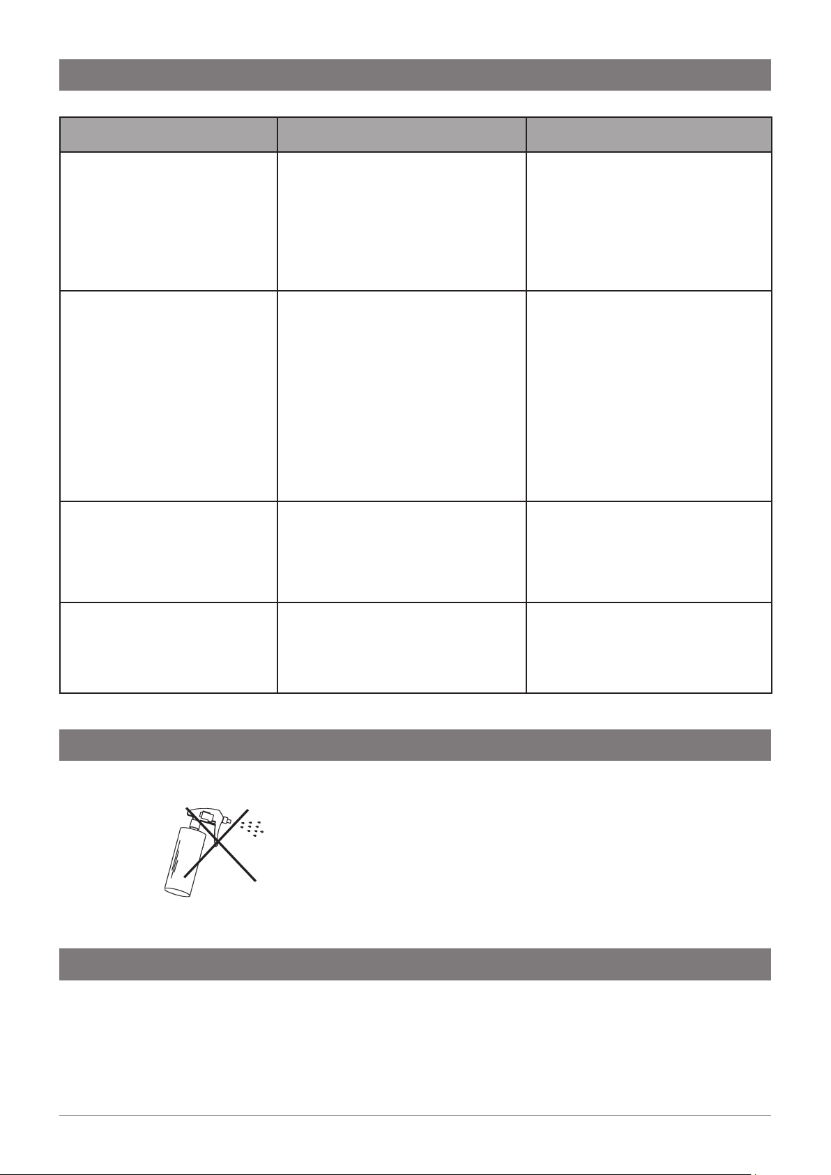
Do not use strong, corrosive, spray or abrasive cleaners. Clean
with a soft cloth or brush and mild soap and water.
Do not spray water over the tap as it may damage the low-
voltage electronics.
Command Centre units must never be cleaned with water jets.
In order to help preserve our environment we ask that you dispose of this product correctly.
Please contact your local city council for collection centre details.
Cleaning
End of Life Disposal
Troubleshooting

12 805757 v1.05 06.21 Miniboil Install Instructions
WMKA00099
AS 3498
Zip Water (Aust) Pty Ltd ABN 46 000 578 727
67-77 Allingham St, Condell Park NSW 2200
Postal: Locked Bag 80, Bankstown 1885 Australia
T: +(61 2) 9796 3100
zipwater.com | 1800 ZIP TAP (1800 947 827)
The terms “Zip” and “HydroTap” are registered trade marks of Zip
Water (Aust) Pty Ltd. Zip products described in this publication
are manufactured under one or more patents and further patent
applications are pending.
As Zip policy is one of continuous product improvement, changes
to specifications may be made without prior notice. Images in this
booklet have been modified and may not be true representations of
the finished goods.
© 2021 Zip Water (Aust) Pty. Ltd.