Loading ...
Loading ...
Loading ...
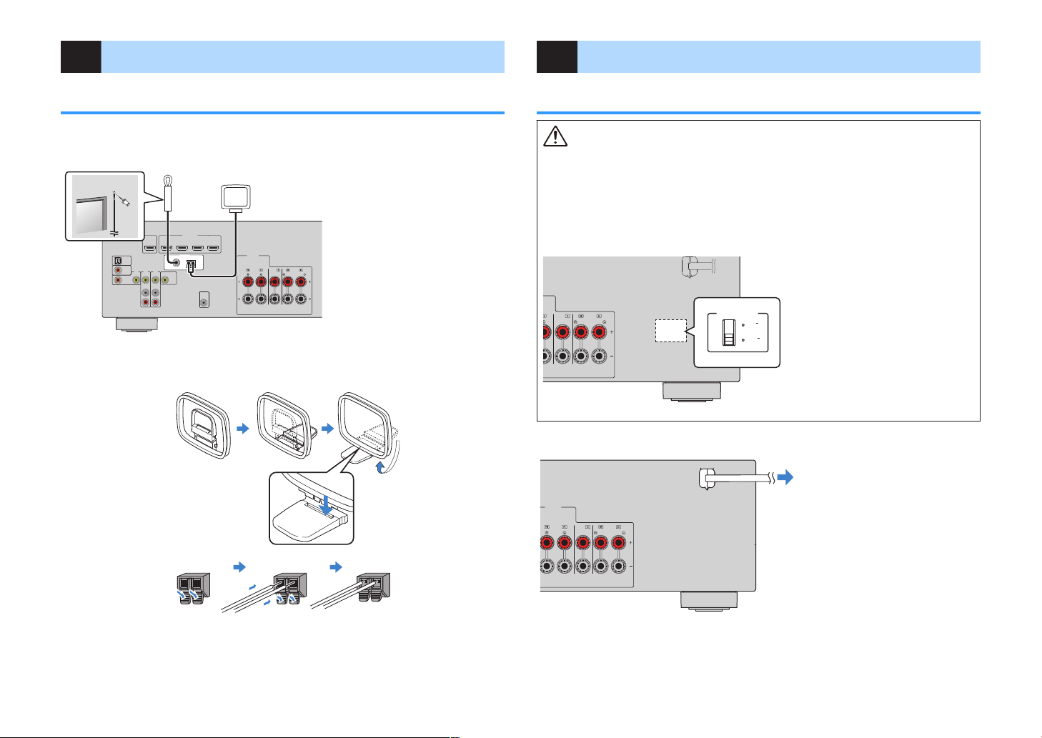
4 Connecting the FM/AM antennas
Connecting the FM/AM antennas
Connect the supplied FM/AM antennas to the unit.
Fix the end of the FM antenna to a wall, and place the AM antenna on a flat surface.
OPTICAL
COAXIAL
COAXIAL
VIDEO
VIDEO
VIDEO
AM
FM
75Ω
ANTENNA
(RADIO)
MONITOROUT
PR
EOUT
SUBWOOFER
HDMI
(HDCP2.2)
(BD/DVD)
2
3
1
4
HDMIOUT
(HDCP2.2)
ARC
FRONT
CENTER
SPEAKERS
SURROUND/BI-AMP
AV3
AUDIO1
AUDI02
AV2
AV1
(TV)
The unit (rear)
FM antenna
AM antenna
Assembling and connecting the AM antenna
ReleaseHold down Insert
Note
▪ Unwind only the length of cable needed from the AM antenna unit.
▪ The wires of the AM antenna have no polarity.
5 Plugging in the power cable
Plugging in the power cable
Warning
(Taiwan, Brazil and Central and South America models only)
Make sure you set VOLTAGE SELECTOR of the unit BEFORE plugging the power cable into an AC wall
outlet. Improper setting of VOLTAGE SELECTOR may cause damage to the unit and create a potential
fire hazard.
Before plugging in the power cable
Set the switch position of VOLTAGE SELECTOR according to your local voltage. Voltages are AC 110–
120/220–240 V, 50/60 Hz.
OPTICAL
COAXIAL
COAXIAL
VIDEO
VIDEO
VIDEO
AM
FM
75Ω
ANTENNA
(RADIO)
MONITOROUT
PR
EOUT
SUBWOOFER
HDMI
(HDCP2.2)
(BD/DVD)
2
3
1
4
HDMIOUT
(HDCP2.2)
ARC
FRONT
CENTER
SPEAKERS
SURROUND/BI-AMP
AV3
AUDIO1
AUDI02
AV2
AV1
(TV)
110V
120V
2
20V
2
40V
VOLT
A
GESELE
CTOR
The unit (rear) VOLTAGE SELECTOR
After all the connections are complete, plug in the power cable.
OPTICAL
COAXIAL
COAXIAL
VIDEO
VIDEO
VIDEO
AM
FM
75Ω
ANTENNA
(RADIO)
MONITOROUT
PR
EOUT
SUBWOOFER
HDMI
(HDCP2.2)
(BD/DVD)
2
3
1
4
HDMIOUT
(HDCP2.2)
ARC
FRONT
CENTER
SPEAKERS
SURROUND/BI-AMP
AV3
AUDIO1
AUDI02
AV2
AV1
(TV)
The unit (rear)
To an AC wall outlet
En
24
Loading ...
Loading ...
Loading ...