

OWNER’S MANUAL
MANUALE UTENTE
XPS 16K
FOUR CHANNELS DSP AMPLIFIER
XPS 16KD
FOUR CHANNELS DSP AMPLIFIER
WITH DANTE


3
CONTENTS
CONTENTS .................................................................................................................................................................. 3
SAFETY PRECAUTIONS AND GENERAL INFORMATION ................................................................................................. 5
SUPPLIED IN THE PACKAGING ................................................................................................................................... 13
XPS 16K CONCEPT .................................................................................................................................................... 14
FRONT PANEL ........................................................................................................................................................... 15
REAR PANEL .............................................................................................................................................................. 16
PROTECTIONS ........................................................................................................................................................... 18
PROCESSING ............................................................................................................................................................. 19
INSTALLATION ........................................................................................................................................................... 21
CONNECTIONS .......................................................................................................................................................... 23
CONTROL .................................................................................................................................................................. 26
DANTE ...................................................................................................................................................................... 29
GPIO ......................................................................................................................................................................... 30
FRONT PANEL HMI .................................................................................................................................................... 32
DIMENSIONS ............................................................................................................................................................. 55
TECHNICAL SPECIFICATIONS ..................................................................................................................................... 56
4
ATTENTION
CAUTION
RISK OF ELECTRIC SHOCK
DO NOT OPEN
CAUTION
WARNING: SHOCK HAZARD – DO NOT OPEN
AVERTISSEMENT : RISQUE D’ELÉCTROCUTION - NE PAS OUVRIR
WARNING: TO REDUCE THE RISK OF FIRE OR ELECTRIC SHOCK DO NOT EXPOSE
THIS EQUIPMENT TO RAIN OR MOISTURE
AVERTISSEMENT : NE PAS EXPOSER CE MATÉRIEL À LA PLUIE OU L’HUMIDITE AFIN
DE REDUIRE LE RISQUE D’INFLAMMATION OU DE CHOC ELÉCTRIQUE
PROTECTING EARTHING TERMINAL. THE APPARATUS SHOULD BE
CONNECTED TO A MAINS SOCKET WITH A PROTECTIVE EARTH
CONNECTION BY 3 POLE POWER CORD.
PROTECTION PAR MISE À LA TERRE. CET APPAREIL DOIT ÊTRE
RACCORDÉ À UNE PRISE DE COURANT AVEC MISE À LA TERRE PAR UN
CORDON D'ALIMENTATION À 3 BROCHES.
5
RCF S.p.A. thanks you for purchasing this product, which has been designed to guarantee reliability and
high performance.
SAFETY PRECAUTIONS AND GENERAL INFORMATION
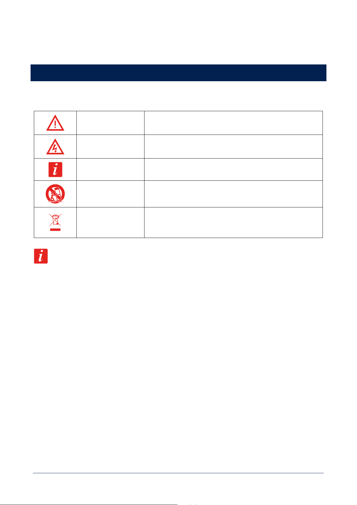
Symbols used in this document give notice of important operating instructions and warnings which must be strictly
followed.
CAUTION
Important operating instructions: explains hazards that could damage a
product, including data loss.
WARNING
Important advice concerning the use of dangerous voltages and the
potential risk of electric shock, personal injury or death.
IMPORTANT NOTES Helpful and relevant information about the topic.
SUPPORTS, TROLLEYS
AND CARTS
Information about the use of supports, trolleys and carts. Reminds to
move with extreme caution and never tilt.
WASTE DISPOSAL
This symbol indicates that this product should not be disposed with your
household waste, according to the WEEE directive (2012/19/EU) and
your national law.
IMPORTANT NOTES
This manual contains important information about the correct and safe use of the device. Before connecting and using
this product, please read this instruction manual carefully and keep it on hand for future reference. The manual is to be
considered an integral part of this product and must accompany it when it changes ownership as a reference for correct
installation and use as well as for the safety precautions. RCF S.p.A. will not assume any responsibility for the incorrect
installation and / or use of this product.
SAFETY PRECAUTIONS
All the precautions, in particular the safety ones, must be read with special attention, as they provide important
information.
1. This is a professional product. Its use is reserved to instructed persons, in relation to the connected risks, as defined
in the IEC 62368-1 3rd Ed. Interfaces at ES2 level present.
2. This equipment is not suitable for use in locations where children are likely to be present.
3. Power supply from mains.
a. The mains voltage is sufficiently high to involve a risk of electrocution; install and connect this product before
plugging it in.
b. Before powering up, make sure that all the connections have been made correctly and the voltage of your mains
corresponds to the voltage shown on the rating plate on the unit, if not, please contact your RCF dealer.
c. The metallic parts of the unit are earthed through the power cable. An apparatus with CLASS I construction shall
be connected to a mains socket outlet with a protective earthing connection.

6
d. Protect the power cable from damage; make sure it is positioned in a way that it cannot be stepped on or crushed
by objects.
e. To prevent the risk of electric shock, never open this product: there are no parts inside that the user needs to
access.
f. Be careful: in the case of a product supplied by manufacturer only with POWERCON connectors and without a
power cord, all power cords and plug assemblies shall be in compliance with the requirements of the IEC 62368-
1 and certified and suitable for use in the particular countries where the product shall be installed.
4. Make sure that no objects or liquids can get into this product, as this may cause a short circuit. This apparatus shall
not be exposed to dripping or splashing. No objects filled with liquid, such as vases, shall be placed on this apparatus.
No naked sources (such as lighted candles) should be placed on this apparatus.
5. Never attempt to carry out any operations, modifications or repairs that are not expressly described in this manual.
Contact your authorized service centre or qualified personnel should any of the following occur:
- The product does not function (or functions in an anomalous way).
- The power cable has been damaged.
- Objects or liquids have got in the unit.
- The product has been subject to a heavy impact.
6. This product does not contain user replaceable fuses. Fuses replacement is a service operation and must be performed
by qualified personnel.
7. The fuse on the AC mains input may be on the neutral, the AC mains shall be disconnected to de-energize the phase.
8. If this product is not used for a long period, disconnect the power cable.
9. If this product begins emitting any strange odours or smoke, switch it off immediately and disconnect the power
cable.
10. Do not connect this product to any equipment or accessories not foreseen. For suspended installation, only use the
dedicated anchoring points and do not try to hang this product by using elements that are unsuitable or not specific
for this purpose. Also check the suitability of the support surface to which the product is anchored (wall, ceiling,
structure, etc.), and the components used for attachment (screw anchors, screws, brackets not supplied by RCF etc.),
which must guarantee the security of the system / installation over time, also considering, for example, the mechanical
vibrations normally generated by transducers. To prevent the risk of falling equipment, do not stack multiple units of
this product unless this possibility is specified in the user manual.
11. RCF S.p.A. strongly recommends this product is only installed by professional qualified installers (or
specialised firms) who can ensure correct installation and certify it according to the regulations in
force. The entire audio system must comply with the current standards and regulations regarding
electrical systems.
12. Supports, trolleys and carts.
The equipment should be only used on supports, trolleys and carts, where necessary, that are recommended
by the manufacturer. The equipment / support / trolley / cart assembly must be moved with extreme caution. Sudden
stops, excessive pushing force and uneven floors may cause the assembly to overturn. Never tilt the assembly.
13. There are numerous mechanical and electrical factors to be considered when installing a professional audio system
(in addition to those which are strictly acoustic, such as sound pressure, angles of coverage, frequency response, etc.).
14. Hearing loss. Exposure to high sound levels can cause permanent hearing loss. The acoustic pressure level that leads
to hearing loss is different from person to person and depends on the duration of exposure. To prevent potentially
dangerous exposure to high levels of acoustic pressure, anyone who is exposed to these levels should use adequate
protection devices. When a transducer capable of producing high sound levels is being used, it is therefore necessary
to wear ear plugs or protective earphones. See the manual technical specifications to know the maximum sound
pressure level.
7
OPERATING PRECAUTIONS
- Place this product far from any heat sources and always ensure an adequate air circulation around it.
- Do not overload this product for a long time.
- Never force the control elements (keys, knobs, etc.).
- Do not use solvents, alcohol, benzene or other volatile substances for cleaning the external parts of this product.
IMPORTANT NOTES
To prevent the occurrence of noise on line signal cables, use screened cables only and avoid putting them close to:
- Equipment that produces high-intensity electromagnetic fields
- Power cables
- Loudspeaker lines
WARNING! CAUTION! To prevent the risk of fire or electric shock, never expose this
product to rain or humidity.
WARNING! to reduce the risk of electric shock, do not disassemble this product
unless you are qualified. Refer servicing to qualified service personnel.
CORRECT DISPOSAL OF THIS PRODUCT
This product should be handed over to an authorized collection site for recycling waste electrical and electronic equipment
(EEE). Improper handling of this type of waste could have a possible negative impact on the environment and human
health due to potentially hazardous substances that are generally associated with EEE. At the same time, your cooperation
in the correct disposal of this product will contribute to the effective usage of natural resources. For more information
about where you can drop off your waste equipment for recycling, please contact your local city office, waste authority or
your household waste disposal service.
CARE AND MAINTENANCE
To ensure a long-life service, this product should be used following these advices:
- If the product is intended to be set up outdoors, be sure it is under cover and protected to rain and moisture.
- Always use a dry cloth to clean the exterior surfaces of the speaker and always do it when the power is turned off.
CAUTION: to avoid damaging the exterior finishes do not use cleaning solvents or
abrasives.

8
FCC NOTES
This equipment has been tested and found to comply with the limits for a Class A digital device, pursuant to Part 15 of
the FCC Rules. These limits are designed to provide reasonable protection against harmful interference when the
equipment is operated in a commercial environment. This equipment generates, uses, and can radiate radio frequency
energy, and if it is not installed and used in accordance with the instruction manual, it may cause harmful interference to
radio communications. Operation of this equipment in a residential area is likely to cause harmful interference, in which
case the user will be required to correct the interference at his own expense.
Modifications: Any modifications made to this device that are not approved by RCF may void the authority granted to
the user by the FCC to operate this equipment.
RCF S.p.A. reserves the right to make changes without prior notice to rectify any errors and / or
omissions. Always refer to the latest version of the manual on www.rcf.it.
9
MESURES DE SÉCURITÉ ET INFORMATIONS GÉNÉRALES
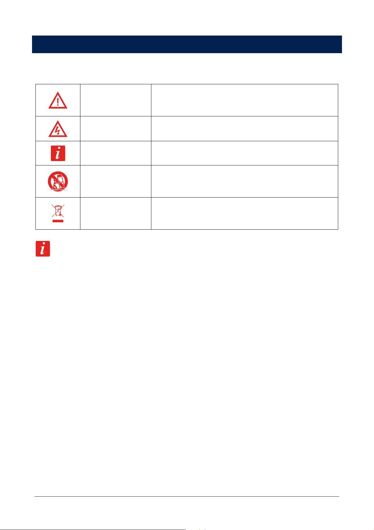
Les symboles utilisés dans ce document signalent des instructions d'utilisation et des avertissements importants qui doivent
être strictement respectés.
ATTENTION
Instructions d'utilisation importantes: expliquent les situations où le
produit pourrait subir des dommages, pouvant impliquer une perte de
données.
AVERTISSEMENT
Conseil important à propos de l'utilisation de tensions dangereuses et le
risque éventuel d’électrisation, de blessure ou de mort.
REMARQUES
IMPORTANTES
Informations utiles et pertinentes sur le sujet.
SUPPORTS, CHARIOTS
ET DIABLES
Informations sur l'utilisation de supports, de chariots et de diables. Nous
vous rappelons que le transport doit s’effectuer avec une extrême
prudence, sans fortes inclinaisons.
ÉLIMINATION DES
DÉCHETS
Ce symbole indique que conformément à la directive DEEE (2012/19/UE)
et à votre législation nationale, ce produit ne doit pas être éliminé en
même temps que vos déchets ménagers.
REMARQUES IMPORTANTES
Ce manuel contient des informations importantes pour utiliser correctement et en toute sécurité l’appareil. Avant de
brancher et d'utiliser ce produit, veuillez lire attentivement ce manuel d'instructions et le garder à portée de main pour le
consulter ultérieurement. Ce manuel doit être considéré comme faisant partie intégrante du produit et doit l'accompagner
lorsqu'il change de propriétaire, afin qu’il serve de référence pour une installation et une utilisation correcte ainsi que pour
les consignes de sécurité. RCF S.p.A. n'assumera aucune responsabilité en cas d'installation et/ou d'utilisation incorrecte
de ce produit.
CONSIGNES DE SÉCURITÉ
Toutes les consignes, en particulier celles relatives à la sécurité, doivent être lues avec attention, car elles donnent des
informations importantes.
1. Ceci est un produit professionnel. Son utilisation est réservée aux personnes formées, en fonction des risques associés,
tels que définis dans la norme IEC 62368-1 3rd Ed. Interfaces de niveau ES2 présentes.
2. Cet appareil ne doit pas être utilisé dans des lieux où des enfants sont susceptibles d'être présents.
3. Alimentation sur secteur.
a. La tension secteur est suffisamment élevée pour entraîner un risque d’électrisation. Installez et connectez ce
produit avant de le brancher au secteur.
b. Avant de le mettre sous tension, assurez-vous que toutes les connexions ont été effectuées correctement et que
la tension secteur correspond à celle indiquée sur la plaque signalétique de l'appareil. Si ce n'est pas le cas,
veuillez contacter votre revendeur RCF.
c. Les parties métalliques de l'appareil sont mises à la terre via le câble secteur. Un appareil de construction de
CLASSE I doit être relié à une prise de courant équipée d’une mise à terre.
d. Protégez le câble d'alimentation contre les dommages. Assurez-vous qu'il est placé de sorte qu'on ne puisse pas
marcher dessus ou l'écraser avec des objets.

10
e. Pour éviter tout risque d’électrisation, n'ouvrez jamais ce produit : il ne contient aucune pièce à laquelle
l'utilisateur a besoin d’accéder.
f. Attention : dans le cas d'un produit fourni par le fabricant uniquement avec des connecteurs POWERCON et sans
cordon d'alimentation, tous les cordons d'alimentation et les prises doivent être conformes à la norme IEC
62368-1 et certifiés et adaptés à l'utilisation dans les pays spécifiques où le produit doit être installé.
4. Assurez-vous qu'aucun objet ou liquide ne peut pénétrer dans ce produit, cela pourrait provoquer un court-circuit.
Cet appareil ne doit pas être exposé à des gouttes ou à des éclaboussures de liquides. Aucun objet contenant un
liquide, un vase par exemple, ne doit être posé sur cet appareil. Aucune source de flamme nue (telle que des bougies
allumées) ne doit être placée sur cet appareil.
5. N'essayez jamais d'effectuer des modifications, des réparations ou de faire fonctionner l’appareil d’une manière non
expressément décrite dans ce manuel. Contactez votre centre de service agréé ou un technicien qualifié dans l’un des
cas suivants :
- Le produit ne fonctionne pas (ou fonctionne de manière anormale).
- Le câble secteur a été endommagé.
- Des objets ou des liquides ont pénétré dans l'appareil.
- Le produit a subi un gros choc.
6. Ce produit ne contient pas de fusibles remplaçables par l'utilisateur. Le remplacement des fusibles est une opération
de réparation qui doit être effectuée par du personnel qualifié.
7. Le fusible de l'alimentation peut être sur le circuit du neutre, l’alimentation secteur doit donc être déconnectée pour
mettre la phase hors tension.
8. Si ce produit n'est pas utilisé pendant une longue période, débranchez le câble secteur.
9. Si ce produit commence à émettre des odeurs inhabituelles ou de la fumée, éteignez-le immédiatement et débranchez
le câble secteur.
10. Ne connectez pas ce produit à des équipements ou accessoires non prévus à cet effet. Pour une exploitation en
accroche, utilisez uniquement les points d'ancrage prévus à cet effet et n'essayez pas d’accrocher ce produit en
utilisant des éléments inadaptés ou non spécifiquement conçus pour cet usage. Vérifier également la compatibilité de
la surface à laquelle le produit est accroché (mur, plafond, structure, etc.), et des composants utilisés pour la fixation
(chevilles, vis, supports non fournis par RCF, etc.), qui doivent garantir la sécurité du système / de l'installation sur la
durée, en tenant compte également, par exemple, des vibrations mécaniques normalement générées par les haut-
parleurs. Pour éviter tout risque de chute de matériel, n'empilez pas plusieurs unités de ce produit, sauf si cette
possibilité est spécifiée dans le manuel d'utilisation.
11. RCF S.p.A. recommande vivement que ce produit soit installé uniquement par des intégrateurs
professionnels qualifiés (ou des entreprises spécialisées) qui pourront garantir une installation
correcte et la certifier selon les normes. L'ensemble du système audio doit être conforme aux normes
et réglementations en vigueur concernant les systèmes électriques.
12. Supports, chariots et diables.
Cet appareil ne doit être utilisé que sur des supports, des chariots et des diables, le cas échéant,
recommandés par le fabricant. L'ensemble appareil/support/chariot/diable doit être déplacé avec une extrême
prudence. Les arrêts soudains, une force de poussée excessive et des sols irréguliers peuvent provoquer le basculement
de l'ensemble. Ne jamais incliner l'ensemble.
13. De nombreux facteurs mécaniques et électriques doivent être pris en compte lors de l'installation d'un système audio
professionnel (en plus des critères strictement acoustiques, comme le niveau de pression sonore, la dispersion, la
réponse en fréquence, etc.).
14. Perte d’audition. L'exposition à des niveaux sonores élevés peut entraîner une perte auditive permanente. Le niveau
de pression acoustique entraînant une perte d'audition est différent d'une personne à l'autre, et dépend de la durée
11
d'exposition. Pour éviter un cumul potentiellement dangereux de niveaux élevés de pression sonore, toute personne
exposée doit utiliser des dispositifs de protection adéquats. Dès que vous utilisez un haut-parleur capable de produire
des niveaux sonores élevés, il est nécessaire de porter des bouchons d'oreille ou un casque anti-bruit. Consultez les
caractéristiques techniques du manuel pour connaître le niveau de pression sonore maximal.
PRÉCAUTIONS D'UTILISATION
- Placez ce produit loin de toute source de chaleur et assurez toujours une circulation d'air adéquate tout autour.
- N’utilisez pas ce produit au-delà de ses spécifications techniques pendant de longues périodes.
- Ne forcez jamais les éléments de contrôle (touches, boutons, etc.).
- N'utilisez pas de solvants, d'alcool, de benzène ou d'autres substances volatiles pour nettoyer les parties externes de
ce produit.
REMARQUES IMPORTANTES
Pour éviter l'apparition de bruit sur les liaisons audio, utilisez uniquement des câbles blindés et évitez de les placer à
proximité :
- d’un appareil produisant des champs électromagnétiques de haute intensité
- de câbles secteur
- de câbles d’enceinte
AVERTISSEMENT ! ATTENTION ! Pour éviter tout risque d'incendie ou d’électrisation,
n'exposez jamais ce produit à la pluie ou à l'humidité.
AVERTISSEMENT ! Pour réduire le risque d’électrisation, ne démontez pas ce produit
à moins de posséder les qualifications requises. Pour les réparations, adressez-vous
à un professionnel qualifié.
ÉLIMINATION CORRECTE DE CE PRODUIT
Ce produit doit être remis à un site de collecte agréé pour le recyclage des déchets d'équipements électriques et
électroniques (EEE). Une manipulation incorrecte de ce type de déchets pourrait avoir un impact négatif sur
l'environnement et la santé humaine en raison de la présence de substances potentiellement dangereuses généralement
associées aux EEE. En même temps, votre coopération dans l'élimination correcte de ce produit contribuera à l'utilisation
raisonnée des ressources naturelles. Pour plus d'informations sur les endroits où vous pouvez déposer vos équipements
usagés pour le recyclage, veuillez contacter votre municipalité ou l'autorité chargée des déchets ou votre service
d'élimination des déchets ménagers.
ENTRETIEN ET MAINTENANCE
Pour garantir une longue durée de vie, voici quelques conseils d’utilisation :
- Si le produit est destiné à être installé à l'extérieur, assurez-vous qu'il est sous abri et protégé de la pluie et de
l'humidité.
- Utilisez toujours un chiffon sec pour nettoyer les surfaces extérieures de l'enceinte et faites-le toujours lorsque
l'appareil est éteint.

12
ATTENTION ! Pour éviter d'endommager les finitions extérieures, n'utilisez pas de
solvants, ni de produit abrasif.
REMARQUES DE LA FCC
Cet équipement a été testé et s’est avéré conforme aux limites d’un appareil numérique de classe A, conformément à la
partie 15 des règlements de la FCC. Ces limites sont conçues pour fournir une protection raisonnable contre les
interférences nuisibles lorsque l’équipement est utilisé dans un environnement commercial. Cet équipement génère, utilise
et peut émettre des ondes radio et, s'il n'est pas installé et utilisé conformément à ce manuel d’instructions, il peut causer
des interférences nuisibles aux communications radio. L’utilisation de cet équipement dans une zone résidentielle peut
causer des interférences nuisibles, que l’utilisateur devra corriger à ses frais.
Modifications : Toute modification apportée à cet appareil et non approuvée par RCF peut annuler l'autorisation
accordée à l'utilisateur par la FCC d'utiliser cet équipement.
RCF S.p.A. se réserve le droit d'apporter des modifications sans préavis afin de rectifier toute erreur
et/ou omission. Consultez toujours la dernière version du manuel sur www.rcf.it.
13
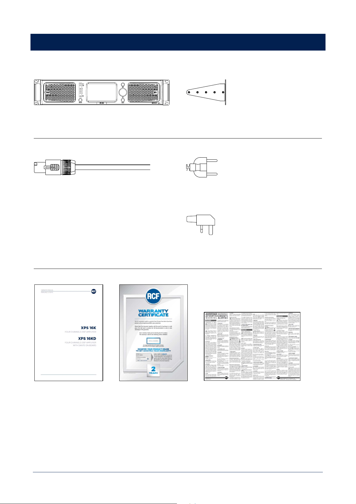
SUPPLIED IN THE PACKAGING
DEVICE (Depending on the part number)
XPS 16K | XPS 16KD
RACK MOUNT ACCESSORIES
2 x rear brackets
POWER CORD
CABLE H07RN-F, 3G2.5, BLACK, 1.2m long
PLUGS (depending on the part number)
SCHUCKO 16A - 250V | IEC 60884-1, CEE7/4, IP 44
POWER PLUG 13A – 250V WITH FUSE | BS1363A/95
DOCUMENTATION
USER MANUAL 2 YEARS WARRANTY WARNING SHEET

14
XPS 16K CONCEPT
XPS 16K represents the new generation of RCF four-channels DSP amplifiers, and offers a full package of extremely high-
power amplification, innovative processing and analogue/digital audio management in a single solution.
It features four, independent processed, channels of audio amplification and can optimize RCF professional speakers’ and
systems’ performance thanks to the on-board dedicated presets library. The powerful multi-DSP architecture, based on
Analog Devices SHARC platform, allows refined equalization and advanced speakers’ management strategies.
XPS implements several safety strategies, both at hardware and firmware levels, to ensure safe and continuous operability
in all operating conditions.
The main user interface is RDNet, the RCF proprietary control and monitoring software that allows to discover, configure,
monitor and control a virtually unlimited number of amplifiers. Users will find ready to use definable parametric
equalizations, multiband compressors, RCF bass shaper, air absorption compensation, delays and levels.
Most of these settings and monitored parameters are also accessible on the front capacitive 4.3’’ touch screen display,
that together with a rotary encoder provides a complete, ergonomic and user friendly HMI.
Third parties control is allowed over OSC protocol, providing interoperability, accuracy, flexibility and other advantages.
XPS 16K has been conceived for both installed sound and touring installation.
15
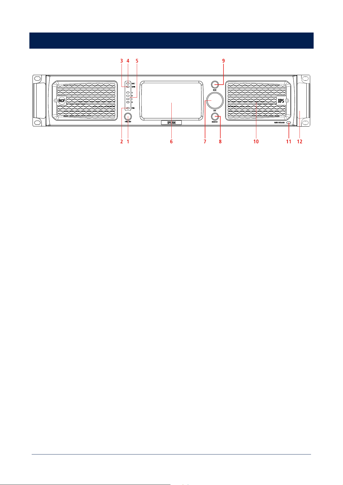
FRONT PANEL
XPS 16K front panel provides a complete set of commands and information useful to configure, monitor and control
amplifier status, behaviour and operability.
1 POWER/STANDBY button
When the amplifier is connected to main supply, press the button switch from STAND BY to ON status.
2 Power LED
RED – standby
YELLOW – starting up
GREEN – device ON
3 Communication LED
YELLOW
4 General fault LED
YELLOW – indicates a general fault has been detected (connected to the FAULT GPO on the rear panel)
5 Output status LED
Show if the signal is:
OFF absent
GREEN present
YELLOW higher than +34 dBu
RED clipping – higher than +43 dBu
6 4.3’’ TFT capacitive touch screen display
Implements all amplifier configuration controls and monitoring information
7 Multifunctional encoder
Allows to navigate the user interface on the display as a support to touch screen interaction
16
8 BACK/ESC button
Short press goes back to previous HMI panel
Long press goes to HOME screen
9 MENU button
Open amplifier MAIN MENU
10 Removable grille with dust filter behind
11 Mains Overload LED
RED – indicated an overload on the mains voltage
12 Metal handles
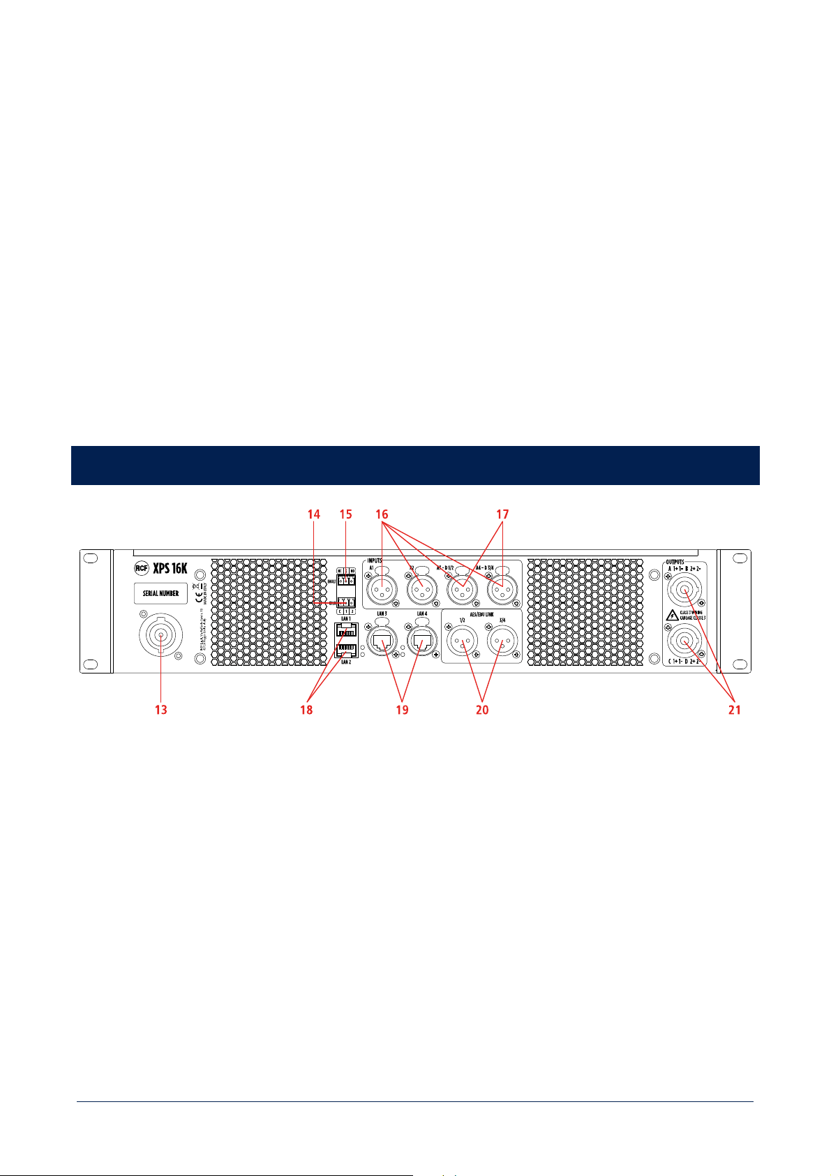
REAR PANEL
13 Mains socket
PowerCON connector
14 2 programmable GPIO
3 pole Euroblock connector
15 General fault GPO
3 pole Euroblock connector working both as NC and NO
16 4 analogue inputs A1 A2 A3 A4
XLR connectors
17 4 digital inputs D1 D2 D3 D4 (alternative to A3 and A4)
Stereo inputs on XLR connectors
17
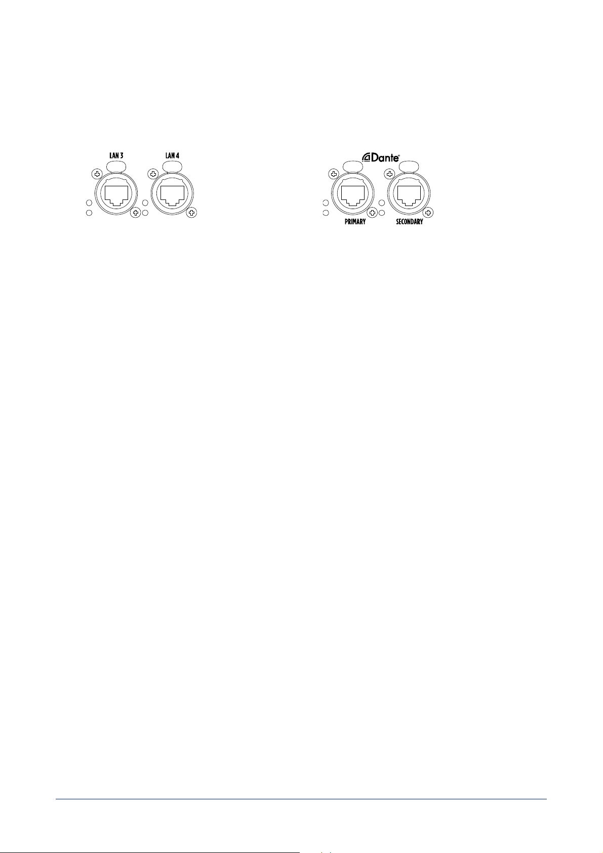
18 LAN1 LAN2 ports
Connect the amplifier for configuration, control and monitoring purpose. RJ 45 connectors.
19 LAN3 LAN4 / DANTE PRIMARY SECONDARY PORTS
XPS 16K
Connect the amplifier for configuration, control and
monitoring purpose. EtherCON connectors.
XPS 16KD
Connect to a DANTE network, for digital audio
distribution. EtherCON connectors.
20 4 digital signal output O1 O2 O3 O4
Stereo digital outputs on XLR connectors
21 Power output
2 outputs on each speakon connector

18
PROTECTIONS
XPS 16K implements several safety strategies, both at firmware and hardware level, to ensure safe and continuous
operability in all operating conditions.
FIRMWARE
1
RMS signal protection on speakers
>
protects transducers from thermal issues
2
Woofer excursion control
>
maintains a precise and powerful driving
3
Power supply output dynamic limitation
>
for high-performance and long-lasting bursts
4
Peak overvoltage protection
>
protects amplifiers in a very responsive way
5
RMS overcurrent protection
>
for short circuit protection
6
Gain modulation for thermal protection
>
calculated by weight
ing the signals of the various temperature
sensors applied to power and amplification modules
Protections 1) and 2) are specific for each RCF speaker, defined and calibrated by RCF electroacoustic technicians.
Firmware modules are written and optimized using the best closed loop control strategies to work in perfect synergy with
hardware protections, which work as fallback protections for the most critical situations.
HARDWARE
1
Current and voltage protections
2
Speakers' impedance measurement
>
allows to monitor power cables connections status, and to devise
speakers’ obsolescence protection strategies
3
Fans forced convection dissipation
>
speed controlled fans, to maximize dissipation with the lowest noise
Protections are classified as:
- Fast protections: very responsive, driven by fast signals, such as overvoltage or power absorptions.
- Slow protections: smooth response, driven by signals with longer inertia, such as thermal ones.

19
PROCESSING
PROCESSING FEATURES
For each channel, XPS 16K provide a full package of advanced processing functions.
Digital Signal Processing (DSP)
2 x SHARC, 40-bit floating point, 96 kHz
2 x ADAU 1442, 32-bit fixed point, 96 kHz
EQ Filters
Peaking
HI/LO-shelving
HI/LO-pass (Butterworth, Linkwitz-Riley, Bessel)
Advanced algorithms
FiRPHASE technology
BASS shaper
Air compensation
Mid-low correction driver excursion control
Dynamic PEQ
Multi-band compressor
Pilot tone & AES detection
Backup recovery strategy
Impedance load measurement
Compressors
RMS limiter
Dynamic compressor
Power limiter
Thermal compressor
Delay
0 ÷ 4000 ms (each channel)
PROCESSING CHAINS
All these features are combined into 4 PROCESSING CHAINS, each one dedicated to a specific speaker type:
- FULL RANGE SPEAKER
- SUBWOOFER
- BI-AMP SPEAKER
- QUAD-AMP SPEAKER
Choosing a specific speaker model, XPS 16K will automatically activate the dedicated processing chain, assuring an
optimized and safe configuration of the system.

20
Due to the complexity of processing chains, not all parameters are available to the final user.
SETTING AVAILABLE TO THE FINAL USER
These parameters can be freely set by the final user:
- Polarity
- User eq
- Delay
ADJUSTMENT AVAILABLE TO THE FINAL USER
There parameters can be adjusted choosing among a predefined set of values:
- Air compensation
- Mid-low correction driver excursion control
- BASS shaper
- Hi-pass filter
- Multiband FiR gain
All other processing parameters are included in the speakers’ preset library and for safety reason, they are not available
for the final user.
21
INSTALLATION
UNPACKING
Check the carton box and its contents and if there is any sign of damage (should the amplifier be damaged, immediately
inform your local distributor / dealer and the forwarder). It is always advisable to keep the packing materials, even if the
amplifier has arrived in good condition. Input and output cables are not included.
ENVIRONMENTAL REQUIREMENTS
XPS 16K amplifiers shall not be installed in a place with:
- too high temperature, dust or excessive humidity;
- exhaust air ventilators;
- permanent vibrations;
- high-intensity electromagnetic fields (due to transformers, transmitters, etc.).
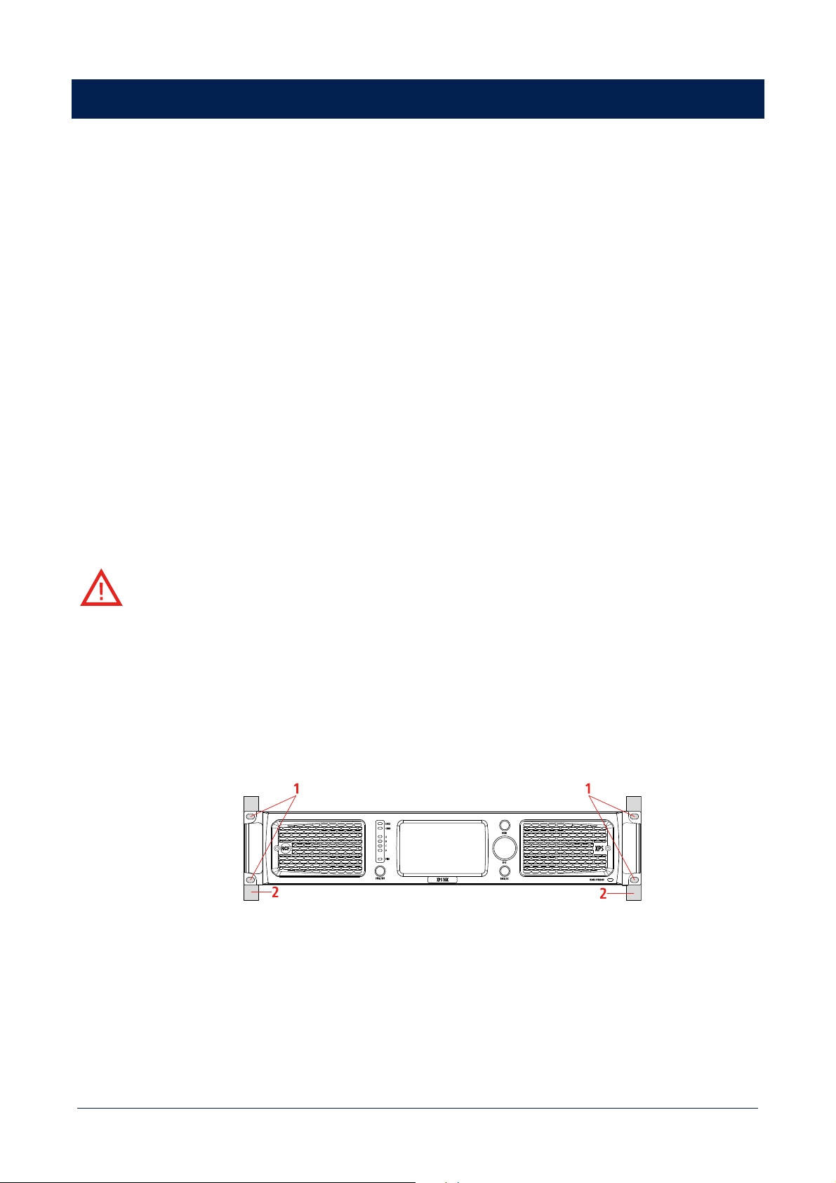
RACK MOUNT
[E] XPS 16K amplifier must be installed inside rack cabinets. Inside rack cabinets, it cannot be installed on slide rails.
[F] L'ampli XPS 16K doit être installé à l'intérieur d'un rack. A l'intérieur des racks, il ne peut pas être fixé sur des
glissières.
1 Fix the XPS 16K amplifier to the rack front uprights (2) using the holes (1) on the supports.
Provide a temporary support during the following steps, in order to avoid accidental product crash and potential
operator injuries.
22
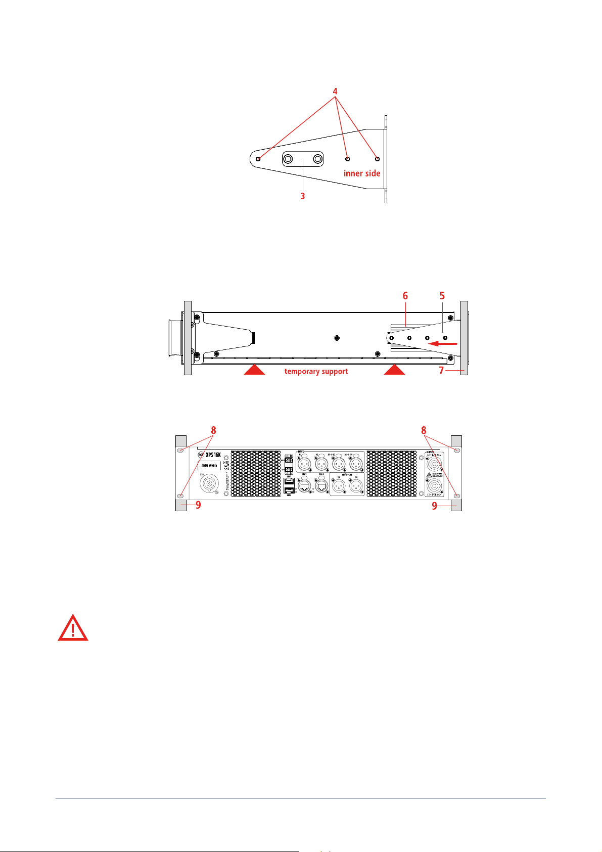
2
Using the holes (4), adjust the position of the bracket insert (3) depending on rack front and rear uprights distance.
3 Insert the rear brackets (5) into the side slides of the frame (6) and push them against the rear uprights of the rack
(7).
4 Fix the XPS 16K amplifier to the rack rear uprights (9) using the holes (8) of the rear brackets.
It is now possible to remove the temporary support.
COOLING
[E] To ensure amplifier operational safety it is crucial to maintain adequate thermal conditions in the installation
environment.
XPS 16K is equipped with 3 variable speed fans that provide the necessary airflow from the front to the rear panel of the
cabinet. In addition, it is necessary to:
- keep the front grilles free from obstacles;
- check the cleanliness of the filters behind the grilles;
- ensure an adequate cool airflow inside rack cabinets, also with additional ventilation modules if they are not vented.
23
[F] Pour garantir le fonctionnement en toute sécurité des amplis, il est essentiel de maintenir des conditions de
température adéquates dans l'environnement d'installation.
Le XPS 16K est équipé de 3 ventilateurs à vitesse variable qui assurent le flux d'air nécessaire, de l'avant vers l'arrière du
châssis. En outre, il est nécessaire de :
- maintenir les grilles avant libres de tout obstacle ;
- vérifier la propreté des filtres situés derrière les grilles ;
- assurer un flux d'air frais suffisant à l'intérieur des racks avec des ventilateurs supplémentaires s'ils ne sont pas
ventilés.
CONNECTIONS
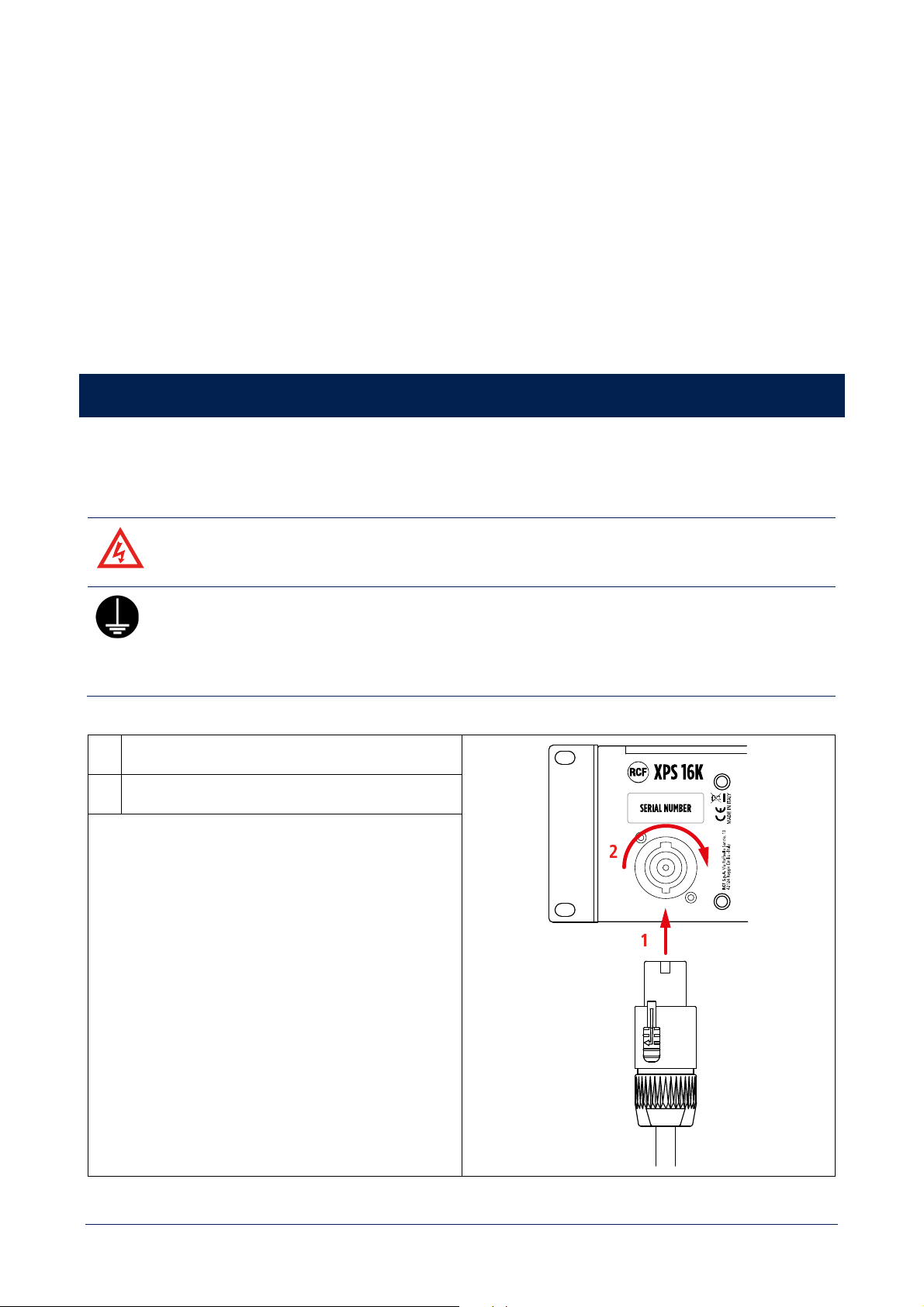
MAINS
[E] WARNING! RISK OF ELECTRIC SHOCK.
[F] AVERTISSEMENT: RISQUE D’ELÉCTROCUTION.
[E] PROTECTING EARTHING TERMINAL. THE APPARATUS SHOULD BE CONNECTED TO A
MAINS SOCKET WITH A PROTECTIVE EARTH CONNECTION.
[F] PROTECTION PAR MISE À LA TERRE. CET APPAREIL DOIT ÊTRE RACCORDÉ À UNE PRISE
DE COURANT AVEC MISE À LA TERRE PAR UN CORDON D'ALIMENTATION À 3 BROCHES.
1
Insert the power cord plug in the MAINS socket
2
Turn the connector clockwise to lock it
CONNECTOR SPECIFICATIONS
NEUTRIK NAC3FC-HC
The PowerCon socket is used to disconnect the device from
the main power source. It must therefore remain easily
accessible after installation.
24
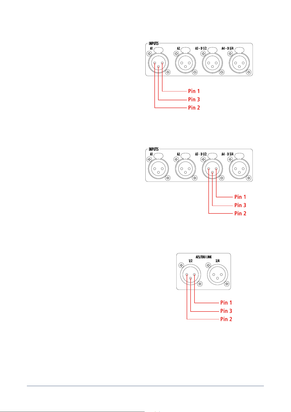
ANALOG INPUTS A1 - A2 - A3 - A4
Pin 1
GND
Pin 2
A1 – 2 – 3 - 4 Signal +
Pin 3
A1 – 2 – 3 - 4 Signal -
CONNECTOR SPECIFICATIONS
3-pole XLR male connector.
AES/EBU DIGITAL INPUTS D1/2 - D3/D4
Pin 1
GND
Pin 2
D1/2 - D3/4 Stereo Signal +
Pin 3
D1/2 - D3/4 Stereo Signal -
CONNECTOR SPECIFICATIONS
3-pole XLR male connector.
AES/EBU DIGITAL AUDIO LINKS O1/2 - O3/4
Pin 1
GND
Pin 2
O1/2 - O3/4 Stereo Signal +
Pin 3
O1/2 - O3/4 Stereo Signal -
CONNECTOR SPECIFICATIONS
3-pole XLR female connector.
25
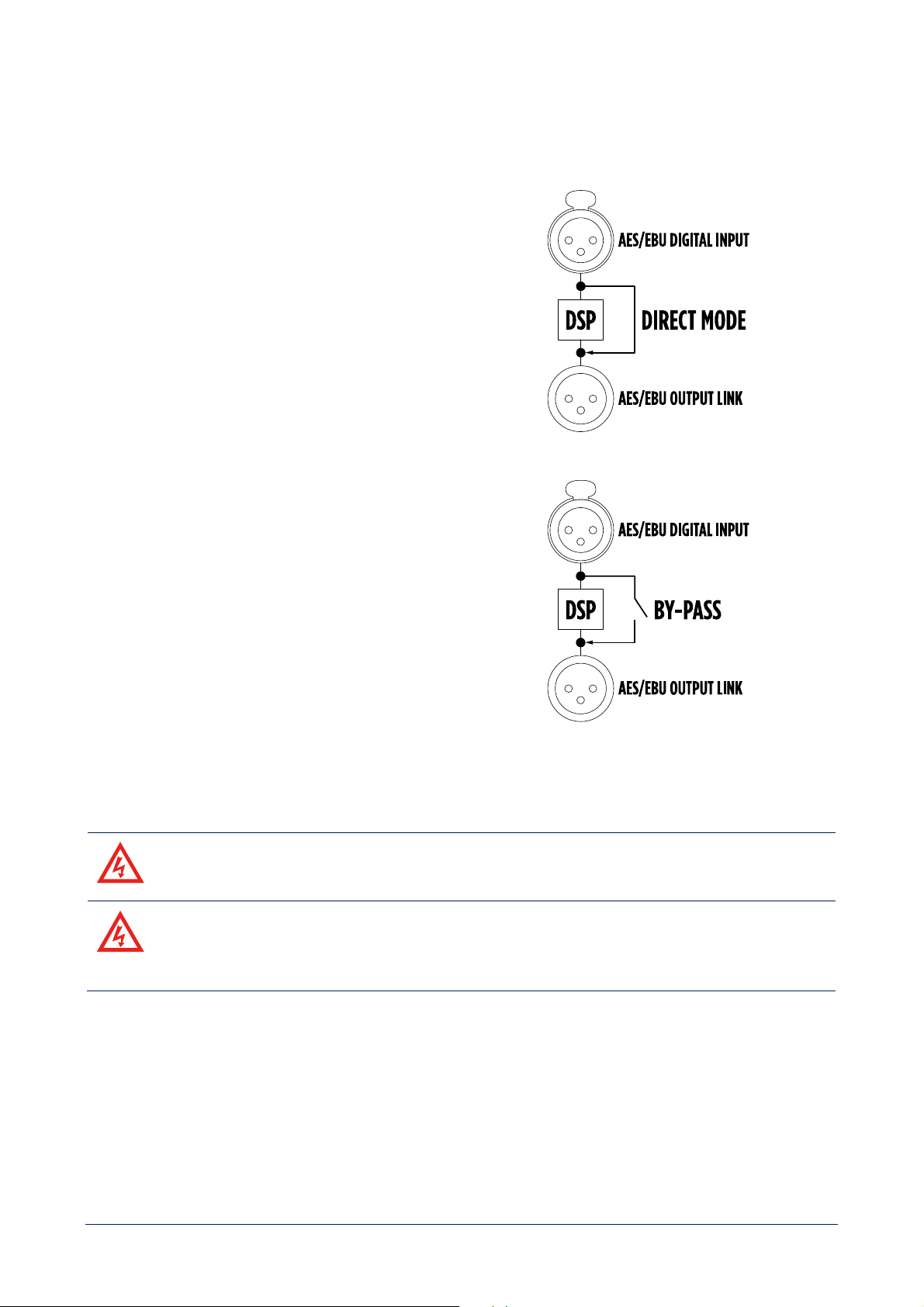
SIGNAL LINK BY-PASS
XPS 16K implements two different DSP by-pass strategies between digital inputs and outputs.
DIRECT MODE
It’s a firmware strategy that by-pass DSP in an active way,
with signal regeneration and negligible delay.
RELAY BY-PASS
It’s a hardware strategy that physically connects inputs and
outputs by closing a n.o. relay in case of absence of power
supply, in order to guarantee the integrity of the signal
path.
OUTPUTS
[E] WARNING! RISK OF ELECTRIC SHOCK.
[F] AVERTISSEMENT: RISQUE D’ELÉCTROCUTION.
[E] WARNING! CLASS 3 WIRING IS MANDATORY FOR THIS EQUIPMENT
[F] AVERTISSEMENT ! UN CÂBLAGE DE CLASSE 3 EST OBLIGATOIRE POUR CET
APPAREIL
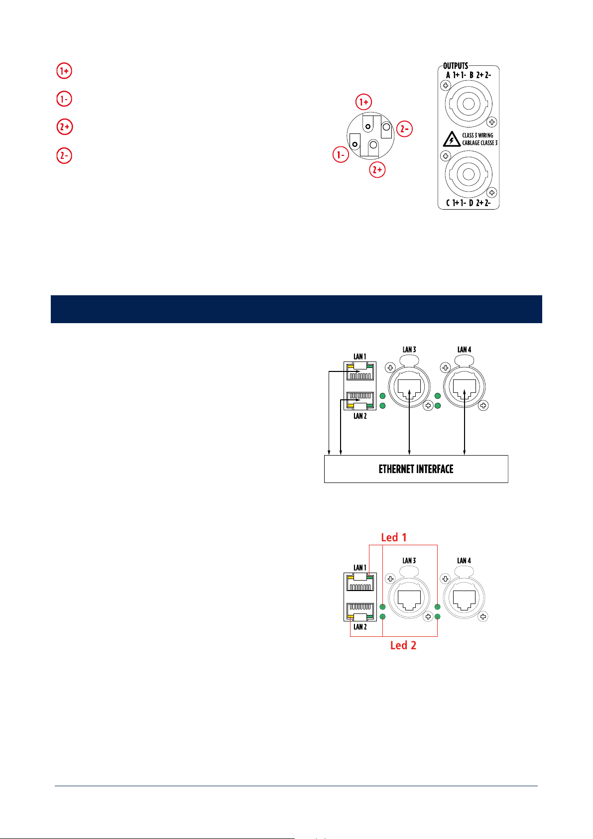
26
Out A – Out C Signal +
Out A – Out C Signal -
Out B – Out D Signal +
Out B – Out D Signal -
CONNECTOR SPECIFICATIONS
4-pole SPEAKON male connector.
CONTROL
XPS 16K features 4 Gigabit Ethernet network ports,
managed by a high-performance switch compliant with
IEEE802.1 AVB standard.
Any of the LAN port can be used as in/out.
It is strongly recommended to reserve a specific
VLAN to the control communication, in order to
guarantee connection performance and
integrity.
Led 1
GREEN – flashing - link/activity
Led 2
YELLOW (LAN 1 and LAN 2) –
GREEN (LAN 3
and LAN 4) – steady – device connected to a
gigabit network.
27
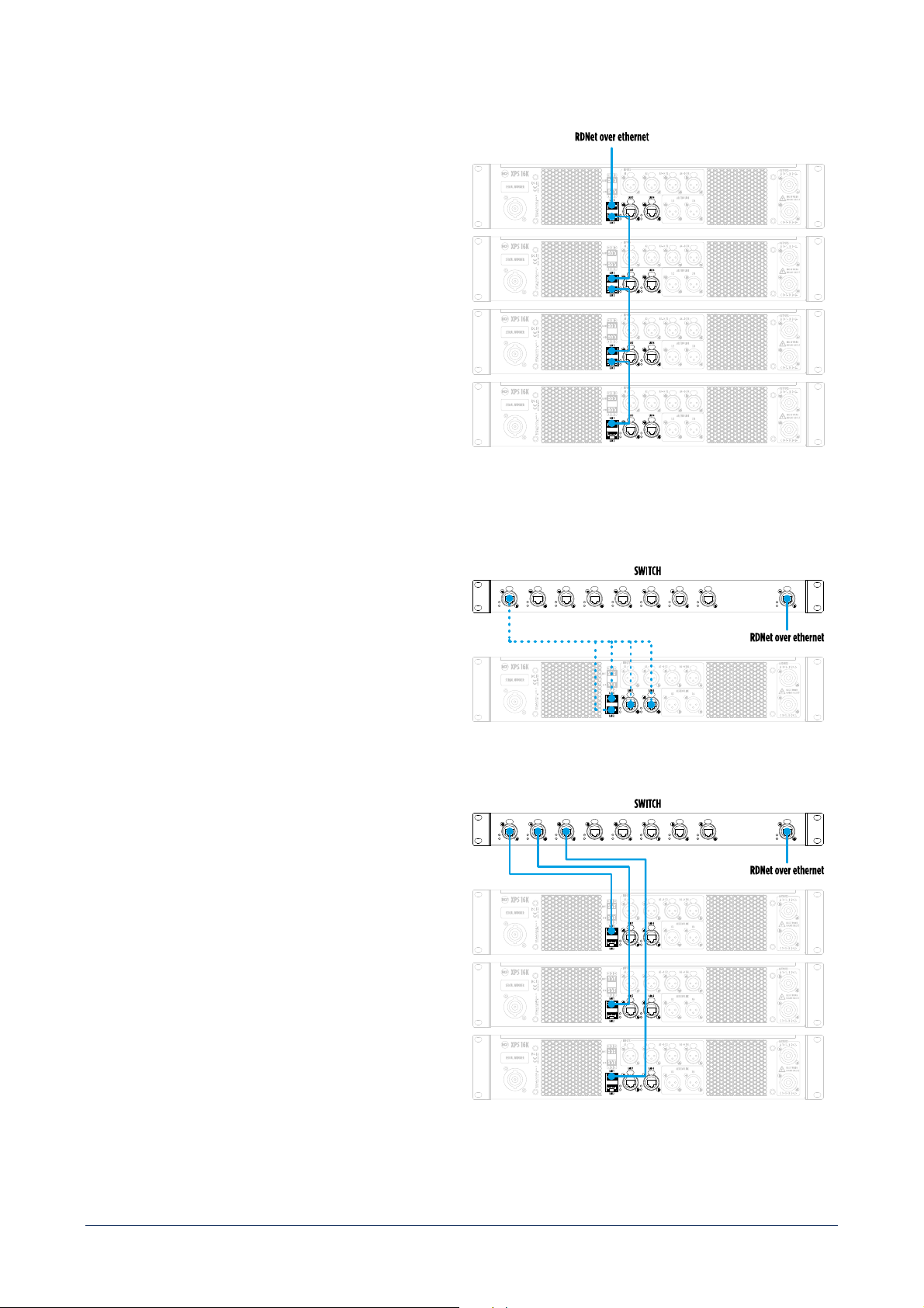
DAISY CHAIN TOPOLOGY
Thanks to the internal switch, XPS 16K can be directly
connected to an ethernet network, and a daisy chain
topology can be built.
The maximum number of devices that can be connected
in daisy-chain depends on the specific user needs in
terms of latency, that necessary increases with the
number of units.
It is good practice not to connect more than 8 units in
daisy chain.
STAR TOPOLOGY
To implement a star topology an external switch is
required.
It can be connected to any of the 4 LAN ports of the
device.
Each XPS 16K device must be connected to a
different switch port.
The maximum number of devices that can be
connected in the same LAN is determined by IPv4
protocol.
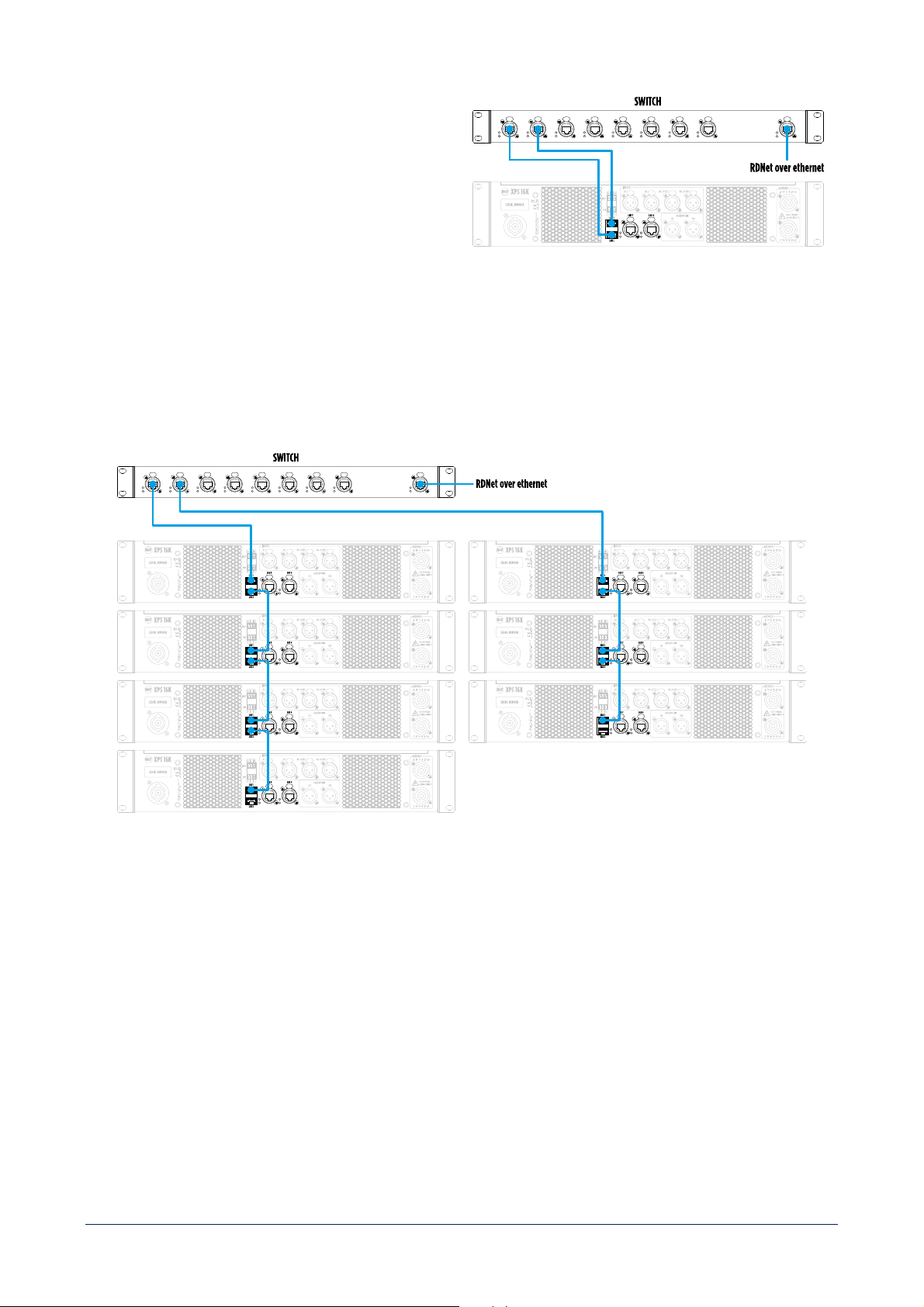
28
Connecting 2 different ports of the device to the
external switch a full redundancy is achieved.
The mandatory requirement is that the external
switch must be managed and support STP.
HYBRID TOPOLOGY
A hybrid topology can also be implemented, with the constraints mentioned above.
29
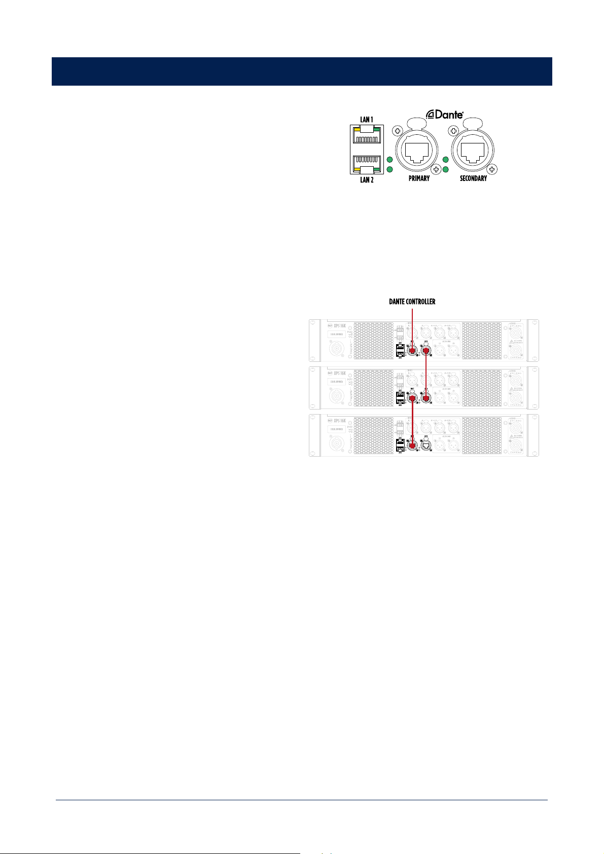
DANTE
The XPS 16KD model is equipped with an Audinate
Brooklyn module, which allows XPS 16K to become a
node in a Dante digital audio distribution network.
In this configuration, LAN 3 and LAN 4 ports become
DANTE primary and secondary ports.
DAISY CHAIN TOPOLOGY
Thanks to the internal switch, XPS 16K can be directly
connected to an ethernet network (and consequently to
DANTE CONTROLLER TOOL), and a daisy chain topology
can be built.
It is strongly recommended to not exceed the number of
3 units connected in daisy chain.
Thanks to the presence of PRIMARY and SECONDARY ports, XPS 16KD allows several configurations with external
switches.
Depending on specific installation needs, it will be necessary to choose the most suitable devices and
topology.
Moreover, in order to guarantee communication robustness and avoid the loss of data packages, it is strongly
recommended to keep audio and control separated into two different vlans.
Accessing Dante module using appropriate software (e.g. Dante Controller) it is possible to switch from the default
connection mode "Switched" to "Redundant". Please refer to the Audinate documentation for connections and possible
switch configurations.
30
GPIO
XPS 16K features General Purpose Inputs and Outputs
contacts, to be connected with other systems
, such as voice
alarm systems.
GPIO – INPUT
Two optoisolated contacts.
Operating modalities:
- LEVEL: high or low;
- TRIGGER: by rising or falling edge.
Available functions:
- POWER ON: (amplifier switched ON at the selected level and switched OFF at the opposite, or toggle ON/OFF by the
selected edge);
- SCENE RECALL: recalls a scene at the selected level or by the selected edge;
- MUTE OUTPUTS: MUTE the selected output channels at the selected level and UN-MUTE them when the level
changes, or toggle MUTE/UN-MUTE by the selected edge);
- INPUT OVERRIDE: enables the override input source at the selected level and disable it at the opposite, or toggle
ENABLE/DISABLE by the selected edge.
Minimum voltage (active input): 2.8V
Maximum voltage (non-active input): 1.5V
Maximum activation voltage: 48V
GPIO – OUTPUT
Two dry contacts.
Operating modalities:
- Normally Open (NO)
- Normally Closed (NC)

31
Available functions:
- FORCE INACTIVE: forces normal condition (test function);
- FORCE ACTIVE: forces opposite condition to the normal one (test function);
- OUTPUT CHANNELS FAULT: enters the opposite condition to the normal one when ALL output channels are in fault
condition.
Maximum voltage at the ends: 48V
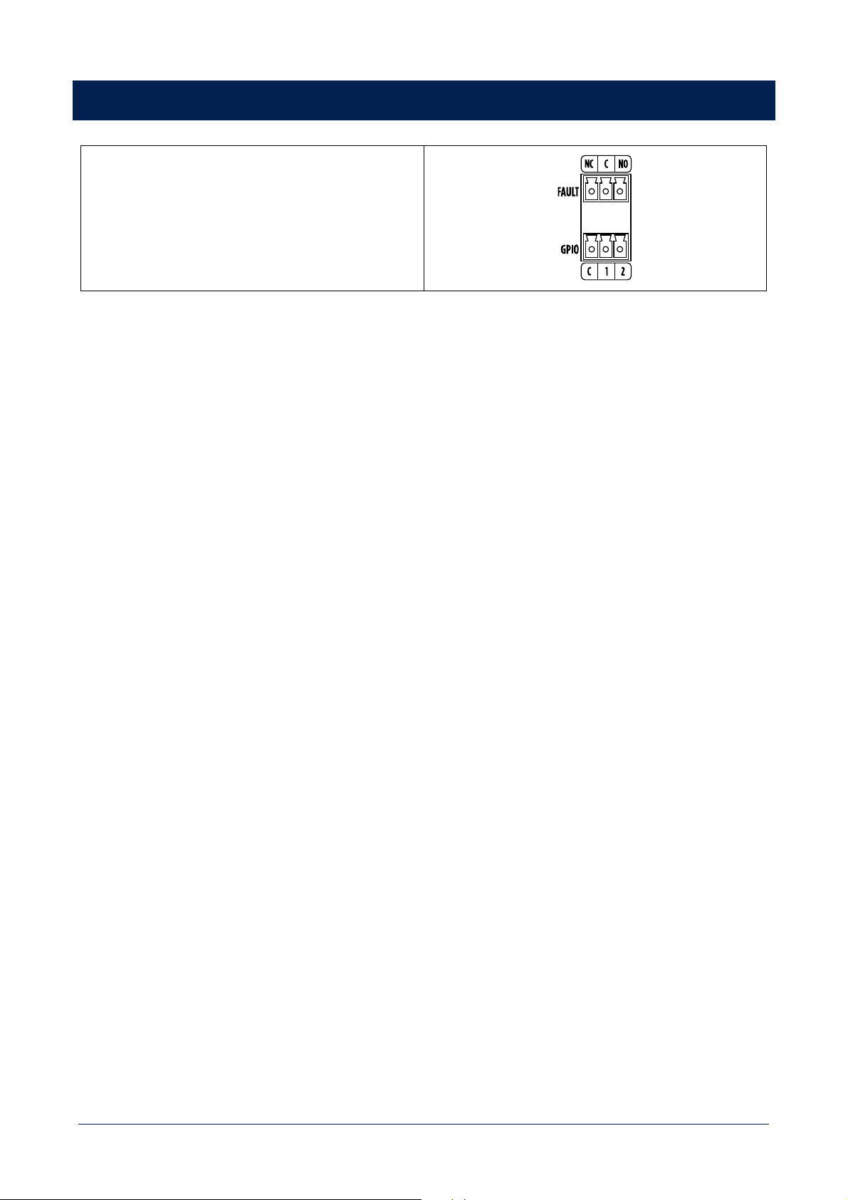
FAULT
Dry contacts.
Operating modalities:
- Normally Open (NO)
- Normally Closed (NC)
It warns of a unit’s GENERAL FAULT. The details of the fault will be shown in the dedicated fault screen.
32
FRONT PANEL HMI
XPS 16K features a complete and ergonomic front panel HMI that allows to configure, control and monitor each XPS 16K
unit.
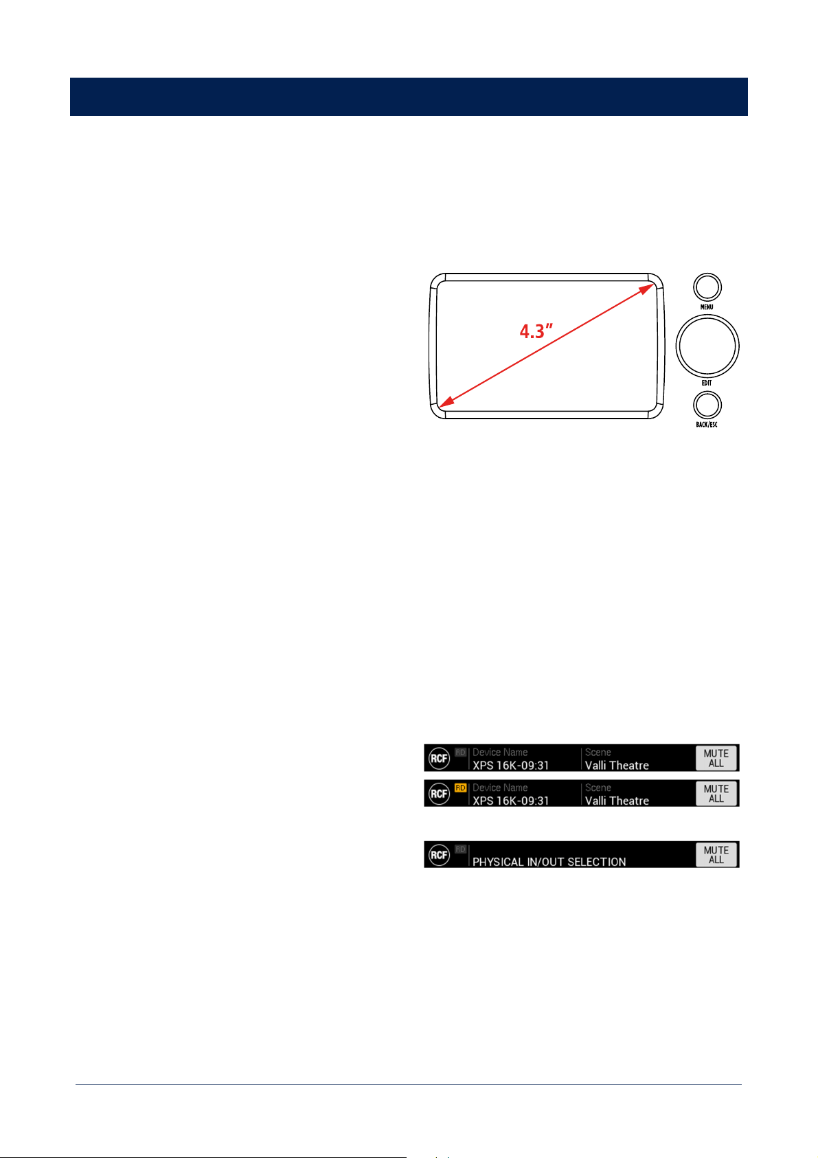
HMI ELEMENTS
DISPLAY
4.3’’ TFT capacitive touch panel with resolution 480*272
pixel.
MENU button
Always link to MAIN MENU screen.
EDIT knob
- Rotation – Navigates screen elements
- Short press – activates elements EDIT mode, confirm
values, change elements status.
BACK/ESC button
- Short press – steps back to the previous HMI screen.
- Long press – go to IDLE screen.
DISPLAY AREAS
HEADER
- RCF logo.
- RDNet connection icon (RD) – When lit YELLOW it
means the amplifier is connected to RDNet software.
- Device Name – shows the name assigned to the
device in the SETTINGS menu section.
- Scene – shows the name of the scene loaded in the
SCENES MANAGEMENT menu section.
- SCREEN TITLE – alternative to Device name and
Scene – contextually shows the screen title.
- MUTE ALL button – mutes all amplifier’s outputs
simultaneously.
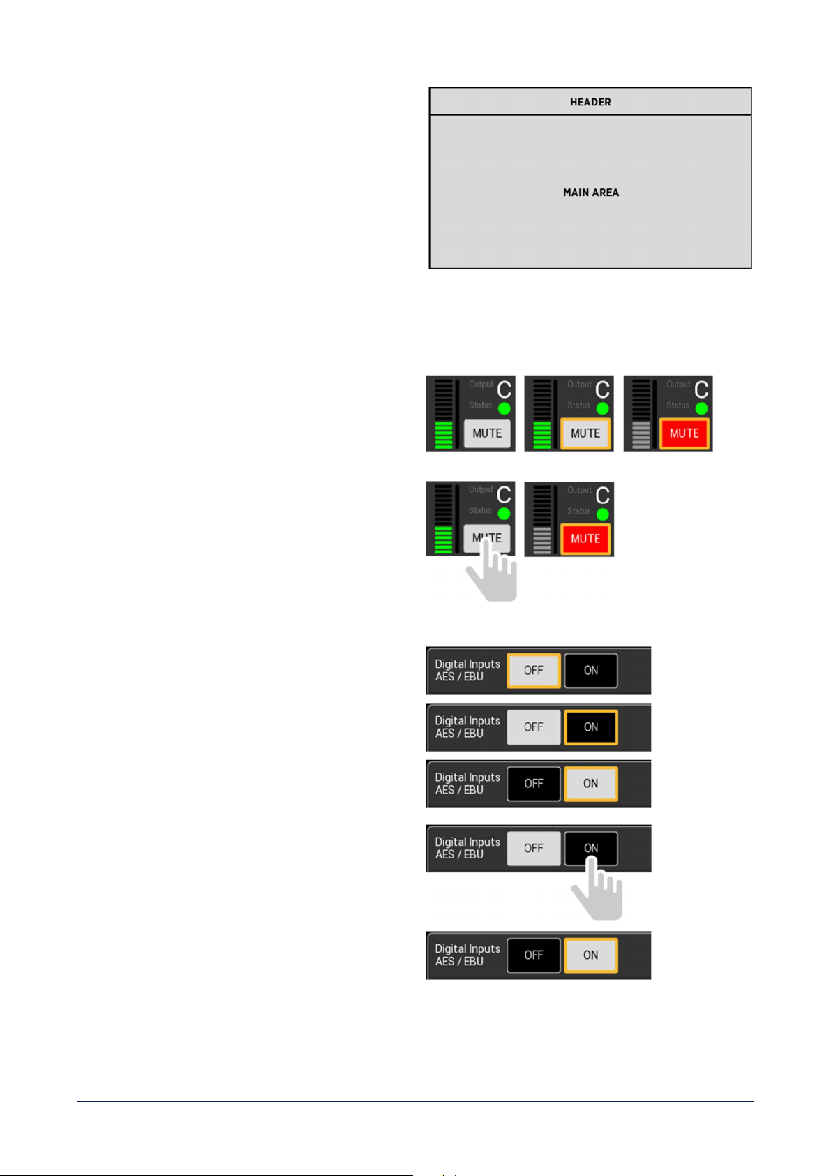
33
MAIN AREA
- Contextually shows information and controls available
in a specific screen.
INTERACTIVE ELEMENTS
BISTABLE BUTTONS
- Rotate the EDIT knob to select the button. Selected
elements are identified by a yellow frame.
- Press the EDIT knob to change the button status.
OR
- Press the button with a SHORT PRESS.
- The button will change its status once released.
- The button will remain selected after press.
TOGGLE BUTTONS
- Rotate the EDIT knob to select the second value.
- Press the EDIT knob to set the second value.
OR
- Press the second value with a SHORT PRESS.
- The value will be set once released.
- The button will remain selected after press.
34
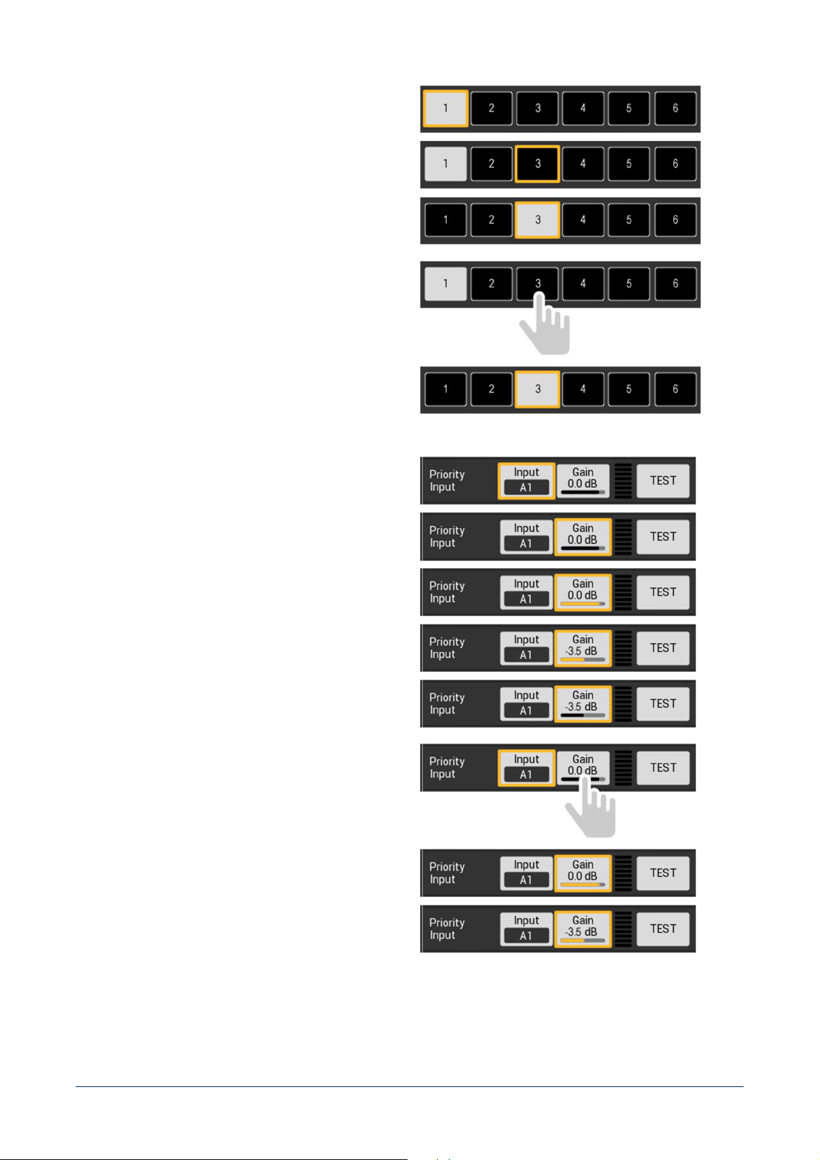
MULTIPLE CHOICE
- Rotate the EDIT knob to select the desired value.
- Press the EDIT knob to set the desired value.
OR
- Press the selected value with a SHORT PRESS.
- The value will be set once released.
- The button will remain selected after press.
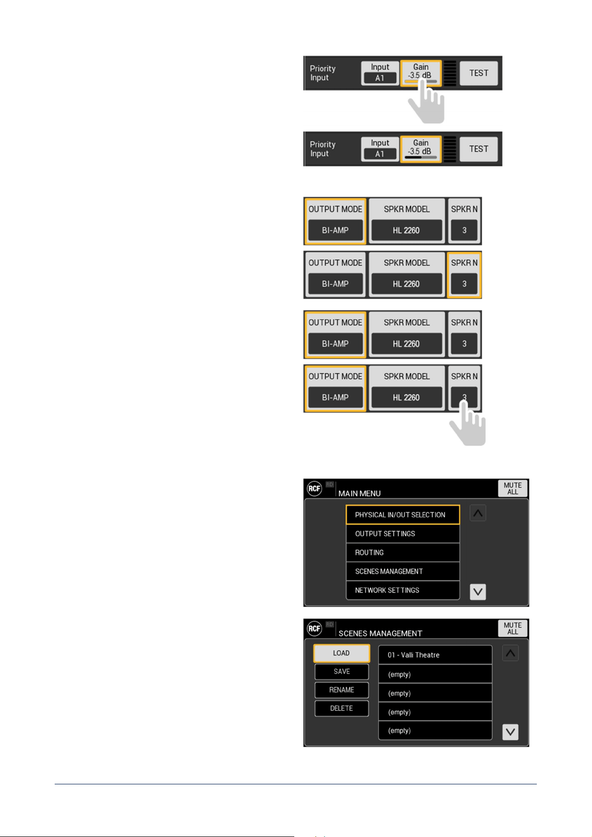
IN-BUTTON VALUE ADJUSTMENT
- Rotate the EDIT knob to select the button.
- Press the EDIT knob to activate adjustment.
- Rotate the EDIT knob to adjust the value.
- Press the EDIT knob to set the value.
A long press of the EDIT knob (1 second) will reset
the parameter to its default value.
OR
- Press the button with a SHORT PRESS.
- Adjustment will be activated once released.
- Rotate the EDIT knob to adjust the value.
- Press the button with a SHORT PRESS to set the
value.
35
SELECTION BUTTON
- Rotate the EDIT knob to select the button.
-
Press the EDIT knob to open the popup window to set
the parameter value.
OR
- Press the button with a SHORT PRESS.
- On button release the popup window to set the
parameter will be opened.
LIST
A list can be both:
- scrolled using the EDIT knob;
- managed by direct selection of the desired item.
Other commands can be present in a list screen
, as shown
in the example.
36
KEYBOARDS
Both alphanumeric and numeric only keyboards are
available, depending on the specific context, to provide
the best tool to user task.
Keyboards can be both:
- scrolled using the EDIT knob;
- managed by direct selection of the desired item.
POPUP WINDOW
It is made of a TITLE BAR and a contextual MAIN AREA
with different contents depending on the specific function.
37
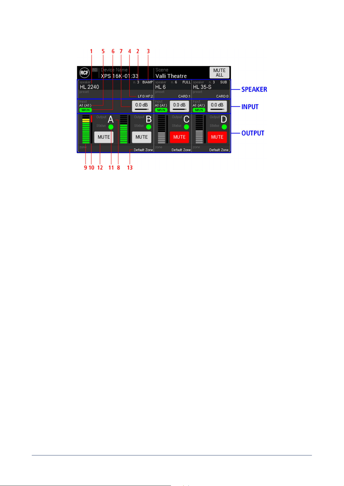
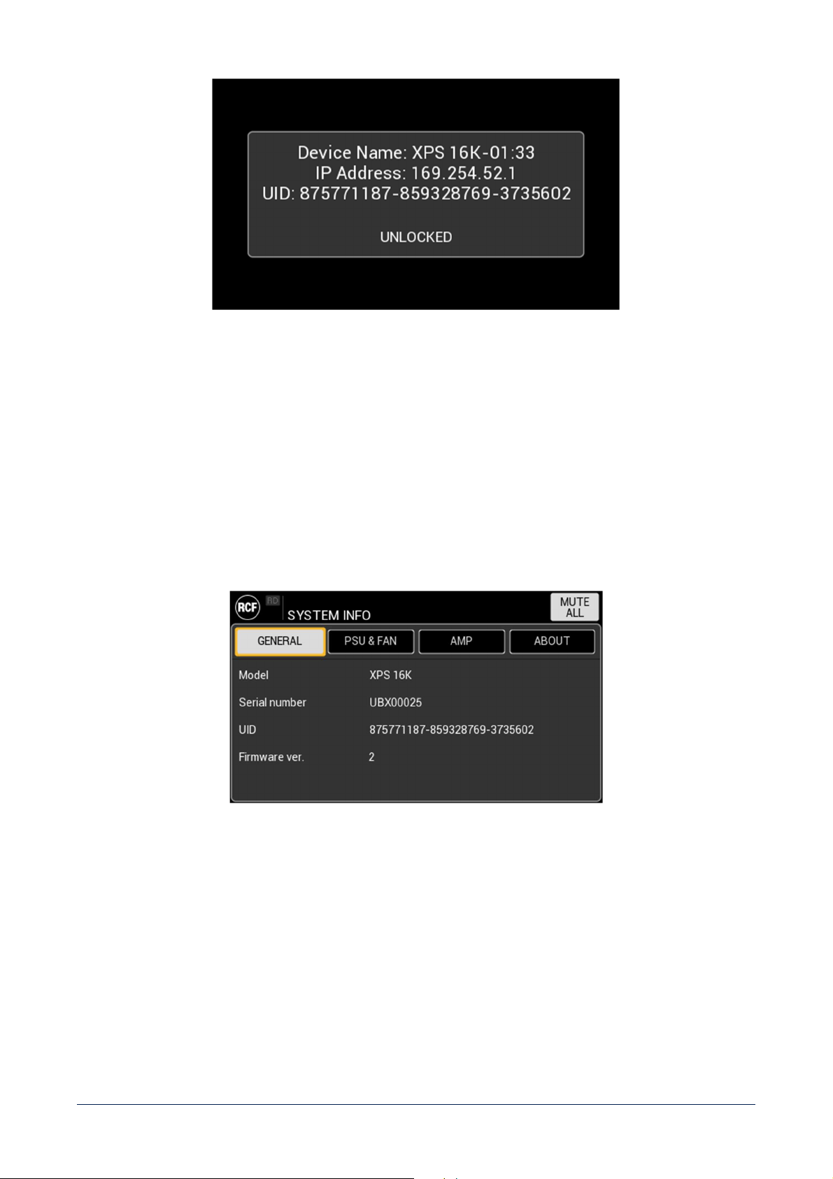
IDLE SCREEN
SPEAKER
1 - SPEAKER MODEL – shows the specific speaker connected to the output(s).
2 - SPEAKER NUMBER – shows the number of speakers connected in parallel to the output(s).
3 - OUTPUT MODE – shows if the speaker is FULL RANGE, SUB, LINE ARRAY, BI-AMP or QUAD-AMP.
4 - SPEAKER PRESET shows the specific preset chosen for the selected speaker.
INPUTS
5 - INPUTS – shows the MAIN and (BACKUP) inputs selected for the specific output.
6 - ACTIVE INPUT– shows the input that is currently routed to output(s).
7 - INPUT GAIN – allows to adjust input gain. It acts both on MAIN and BACKUP inputs gain.
OUTPUT
8 - OUTPUT CHANNEL (A – B – C – D) – shows the label of the specific output.
9 - OUTPUT VU METER
10 - GAIN REDUCTION METER – indicates the level of gain reduction from 0 dB to 60 dB (fully RED bar). The
graphic indicator is linear, so half red bar means a gain reduction of 30 dB.
11 - CHANNEL STATUS – depending on the colour:
- GREY channel works correctly, and the impedance monitoring is deactivated;
- GREEN channel works correctly, the impedance monitoring is active and it is measuring a
value within the range set;
- YELLOW channel works correctly, the impedance monitoring is active and it is measuring a
value out of range set;
38
- RED channel shutdown (the cause is detailed in the dedicated AMP tab in SYSTEM INFO).
12 - MUTE button – mutes the specific amplifier’s output(s) channel.
13 - ZONE – shows the name assigned to the output(s) zone.
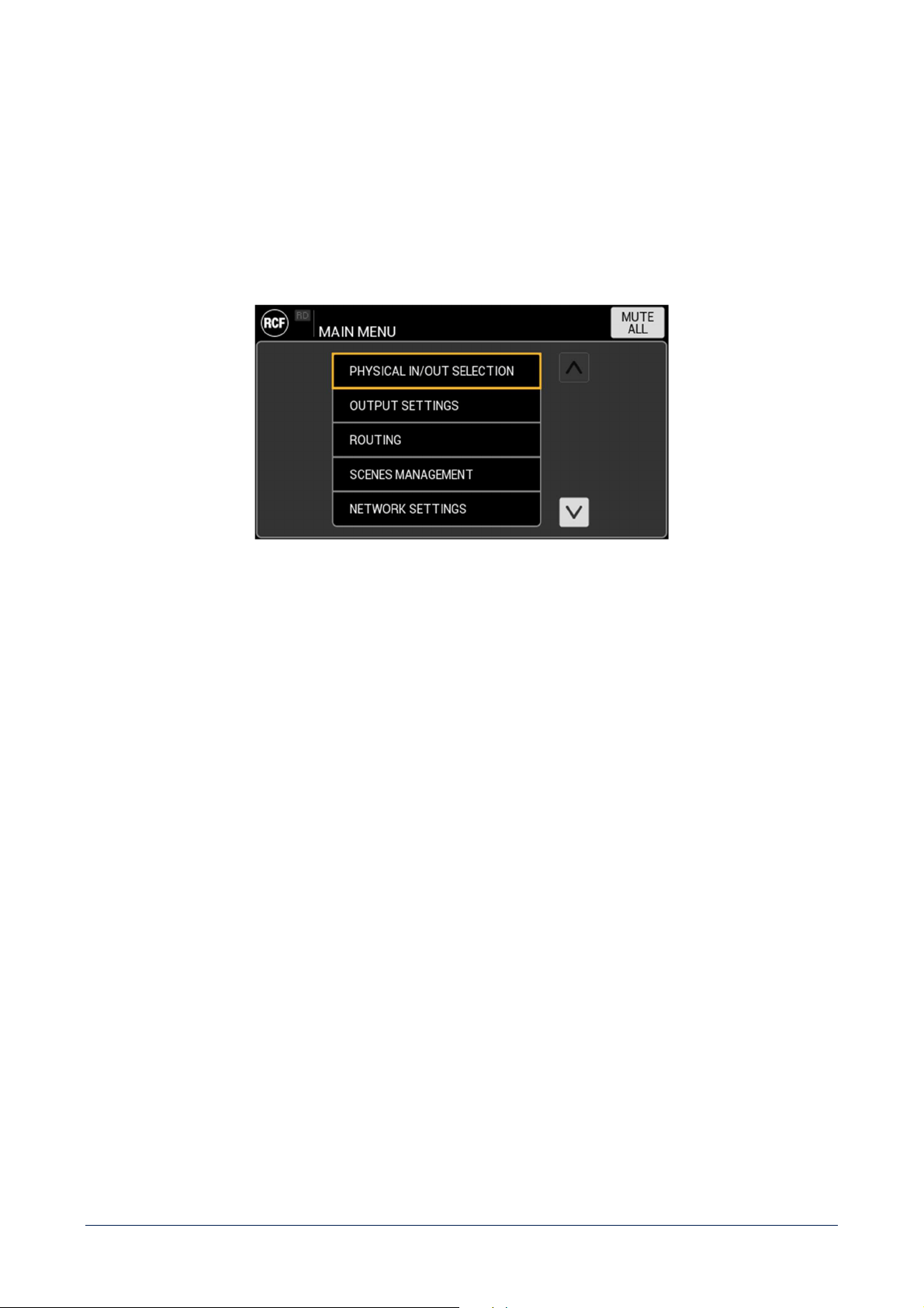
MAIN MENU
It is a list of the following items:
- PHYSICAL IN/OUT SELECTION
- OUTPUT SETTINGS
- ROUTING
- SCENES MANAGEMENT
- NETWORK SETTINGS
- REMOTE CONTROL
- DEVICE SETTINGS
- SYSTEM INFO
39
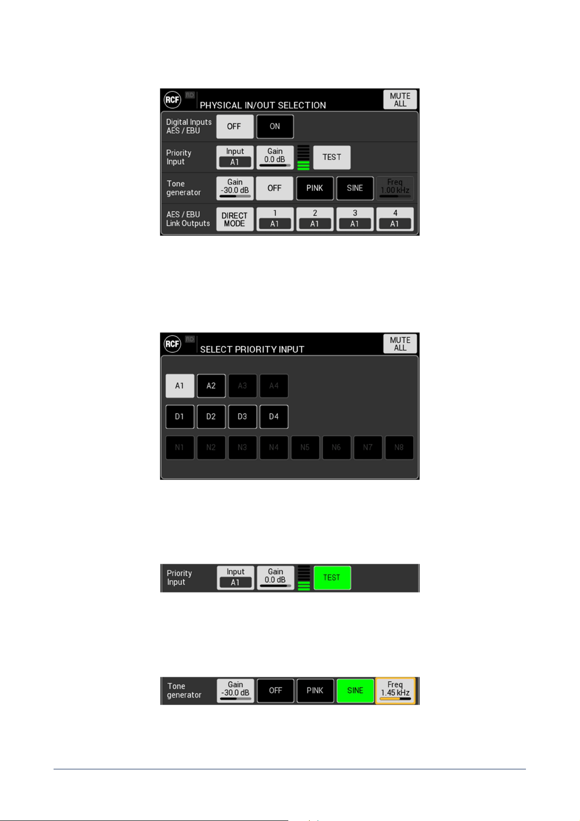
PHYSISCAL IN/OUT SELECTION
Digital Inputs AES/EBU – Enable / disable 4 digital inputs AES/EBU (D1 - D2 - D3 e D4) alternative to analogue
inputs A3 and A4. These inputs are physically allocated on two connectors.
Priority Input – set the Input to be used as priority over GPI command.
In the XPS 16KD model, DANTE input N1 – N8 are available.
Also adjusts Priority Input gain and shows VU meter.
TEST button routes Priority Input to all output for test purpose. When active, the button is GREEN.
Tone generator – adjust Tone generator gain and activate it choosing between PINK noise and SINE.
When SINE is active, it is possible to set the related frequency.
40
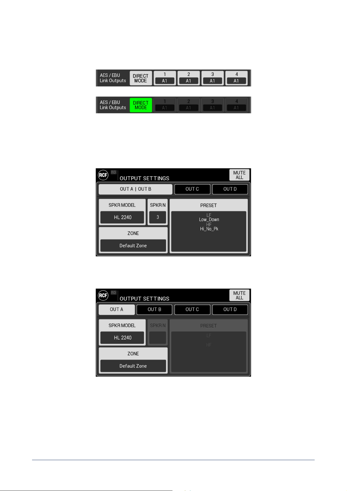
AES/EBU link outputs - set the Inputs to be routed on O1 – O4 digital signal outputs.
When Digital Inputs AES/EBU are active, DIRECT MODE function is available. If activated, it by-
bass the signal processing
and automatically assigns D1 to O1, D2 to O2, etc.
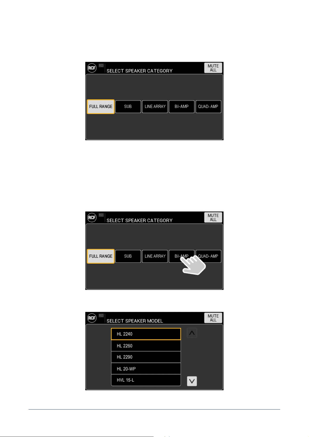
OUTPUT SETTINGS
This HMI section allows to completely configure amplifiers outputs channels. Starting from a blank screen, the
interaction flow is described in the following example.
41
SPKR MODEL
Allows to choose the specific speaker model connected to amplifier’s output(s) channel(s) within the RCF speakers’
library. This command links to the selection of the SPEAKER CATEGORY, and provide a first level filter of the library:
It is possible to choose among:
- FULL RANGE – full range speaker, connected to a single output channel.
- SUB – subwoofer, connected to a single output channel.
- LINE ARRAY – line array speaker, with specific chain features.
- BI-AMP – bi-amped speaker. One channel used for LF and one for HF (or MF + HF with crossover).
- QUAD-AMP – quad-amped speaker, with two different channels for LF, one for MF and one for HF.
After this choice, the list of available speakers in the specific category is provided:
42
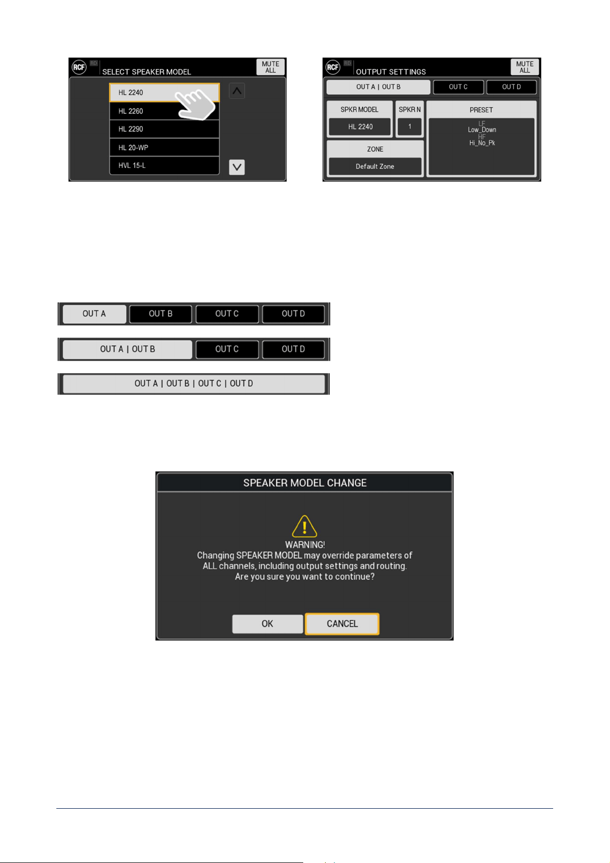
Choosing the speaker model from the list, the number of connected speakers (SPKR N) and PRESET will be set to the
default value.
Moreover, channels tabs automatically adapt to the SPEAKER CATEGORY setting:
TABS CONFIGURATION SPEAKER CATEGORY
FULL RANGE or SUB
BI-AMP
QUAD-AMP
Changing the SPEAKER MODEL setting, all outputs and routing parameters will be consequently reset.
A confirmation popup will ask user to confirm the action.
43
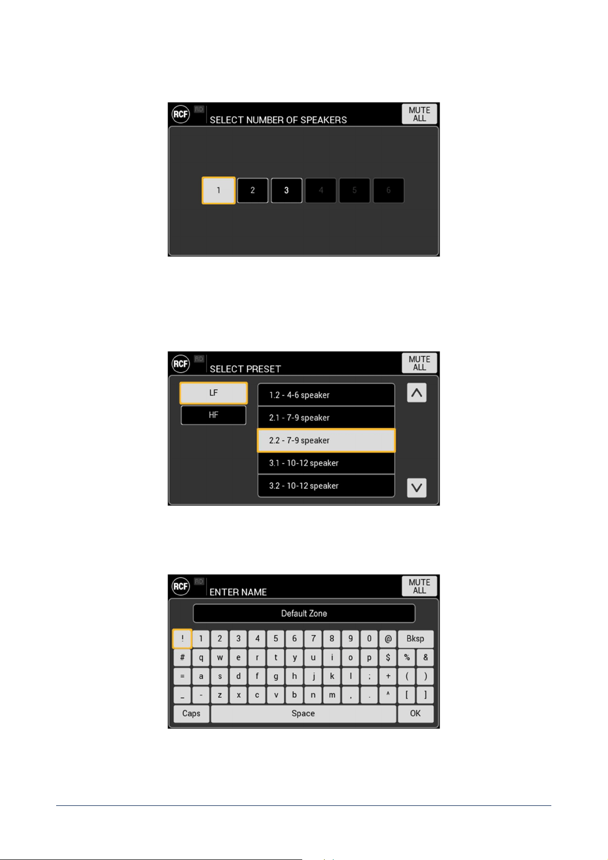
SPKR NUMBER – Set the number of speakers connected in parallel. The number will be coherent with SPEAKER
MODEL in terms of maximum power and impedance.
PRESET – set the preset for the selected SPEAKER MODEL. Its structure reflects the SPEAKER CATEGORY, and
automatically adapts to speaker type. Depending on it, different preset options will be offered, such as Low Frequencies
and High Frequencies for bi-amp speakers, Hi-Pass and Low-Pass filters for subwoofers, etc.
ZONE – Set the name of the zone served by the speakers connected to the output(s).
44
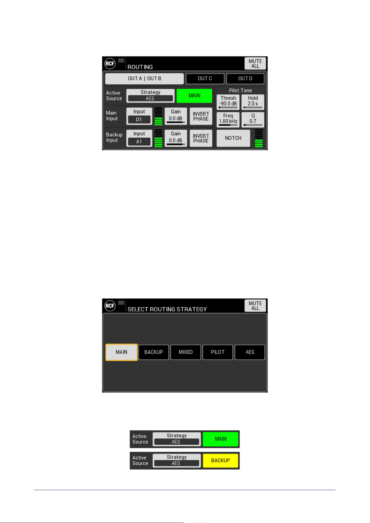
ROUTING
Set the parameters that define the routing configuration of the device. Settings are available for each output,
depending
on selected OUTPUT MODE.
Active Source
STRATEGY – choose the routing strategy among:
- FORCE MAIN – routes the MAIN INPUT on the selected output(s).
- FORCE BACKUP – routes the BACKUP INPUT on the selected output(s).
- MIXED – MAIN and BACKUP INPUTS are summed, and the resulting is attenuated by 6dB.
- PILOT TONE – routes the MAIN INPUT as long as the pilot tone is detected on the speaker line. In case of
absence, switches on BACKUP INPUT.
- AES – routes the MAIN INPUT as long as the clock is detected. In case of absence, switches on BACKUP INPUT.
This strategy is available only if a DIGITAL AES/EBU input is selected as MAIN input.
The active source is shown on the right side of the STRATEGY and automatically shows one of the following:
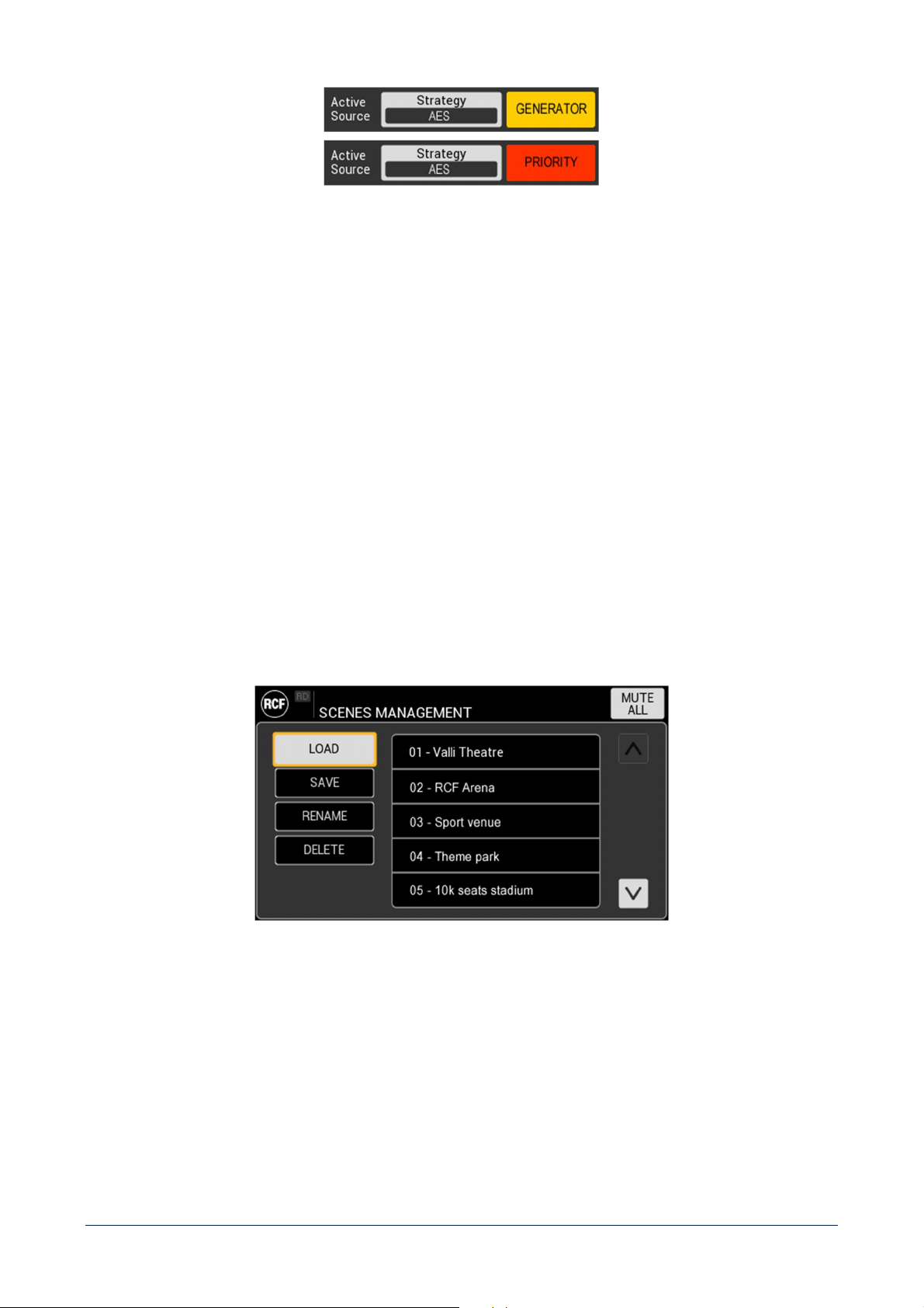
45
Main Input – Select input, shows VU meter, set gain and invert polarity.
Backup Input – Select input, shows VU meter, set gain and invert polarity.
Pilot Tone – Set function parameters:
- Threshold –the level under which the pilot tone is considered not detected, and trigger the switch from MAIN to
BACKUP inputs.
- Hold time – the time lapse the tone must stay under the threshold to be considered not detected.
- Frequency – frequency on which the pilot tone detection filter is tuned.
- Q – Quality Factor of the pilot tone detection filter.
- NOTCH – activates filter to cancel the pilot tone in reproduction.
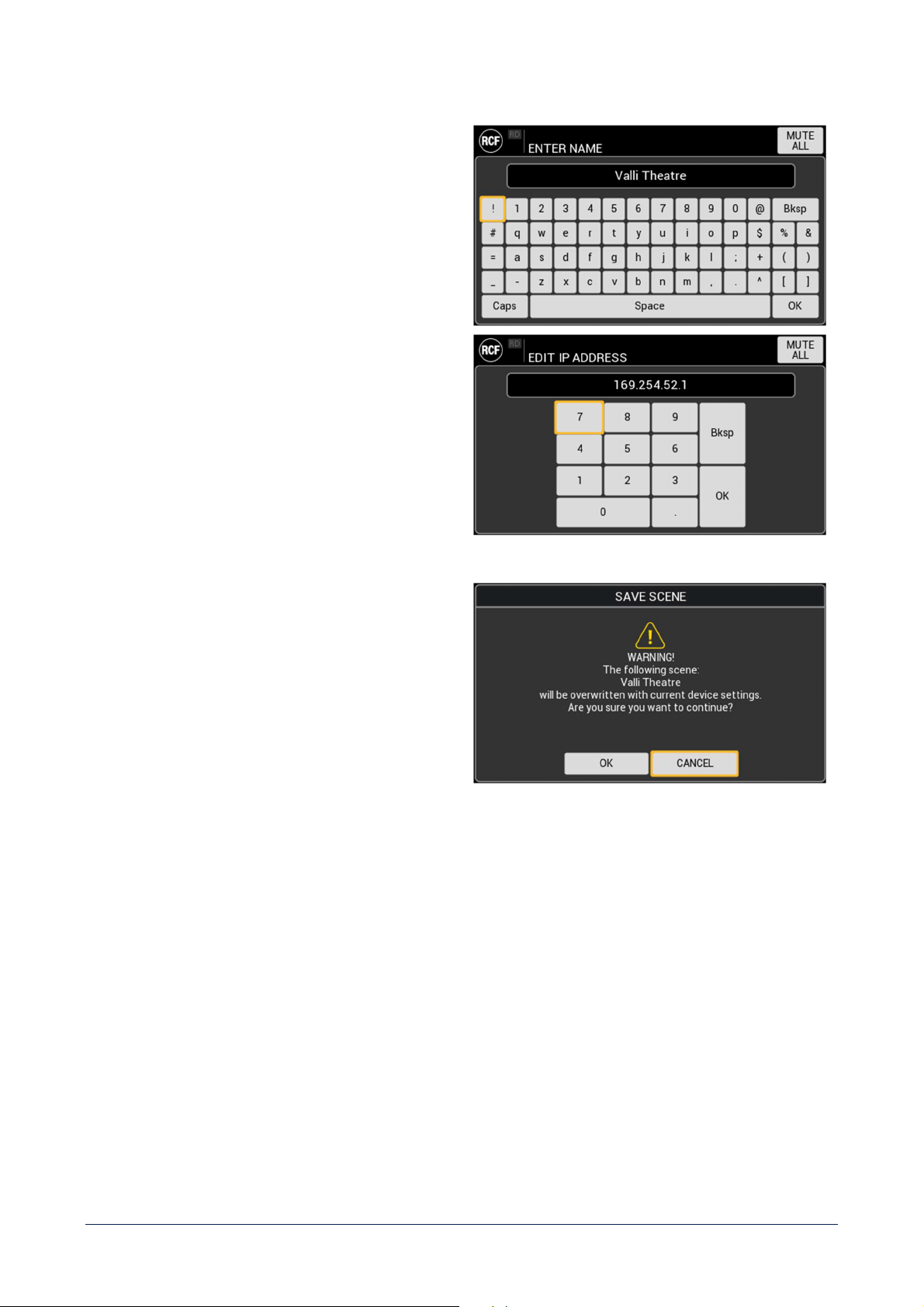
SCENES MANAGEMENT
It shows the list of the scenes saved on the device. The toggle buttons on the left side of the screen provide the related
function.
46
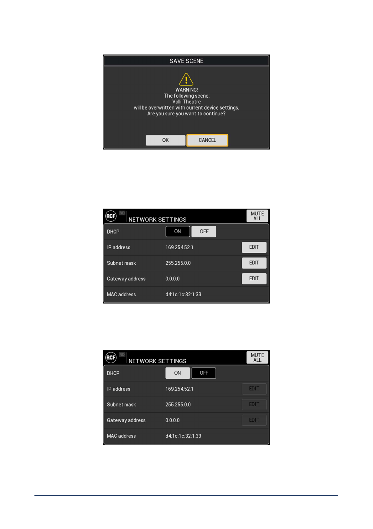
If the user tries to overwrite an existing SCENE, a popup will ask to confirm before proceeding.
NETWORK SETTINGS
DHCP – set Dynamic Host Configuration Protocol ON or OFF. If set ON, the following parameters IP address, Subnet
mask and Gateway address are assigned automatically and not editable.
47
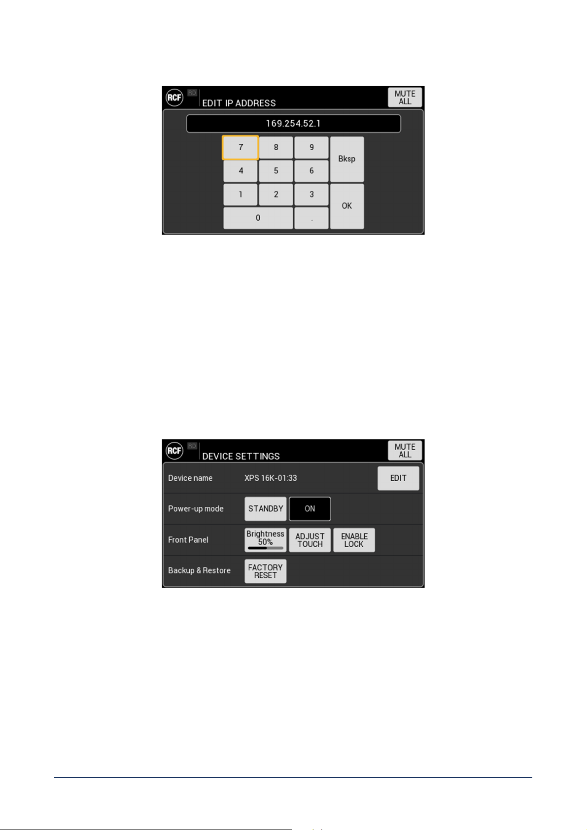
IP address – set the parameter using the context related keyboard (accepted formats 8.8.8.8, 8.8.16 and 8.24):
Subnet mask – set the parameter using the context related keyboard.
Gateway address – set the parameter using the context related keyboard.
MAC address – shows device MAC address (read only)
DEVICE SETTINGS
Device name – set a custom name for the device, to better identify it in a system.
Power-up mode – define the status the device will start up when connected to the main. If set to ON, the device will
completely power-up, automatically executing the POWER/STANDBY button function via firmware.
48
Front panel – set parameters related to front panel components behaviour:
- Brightness – adjust display brightness level
- ADJUST TOUCH – start touch screen calibration procedure
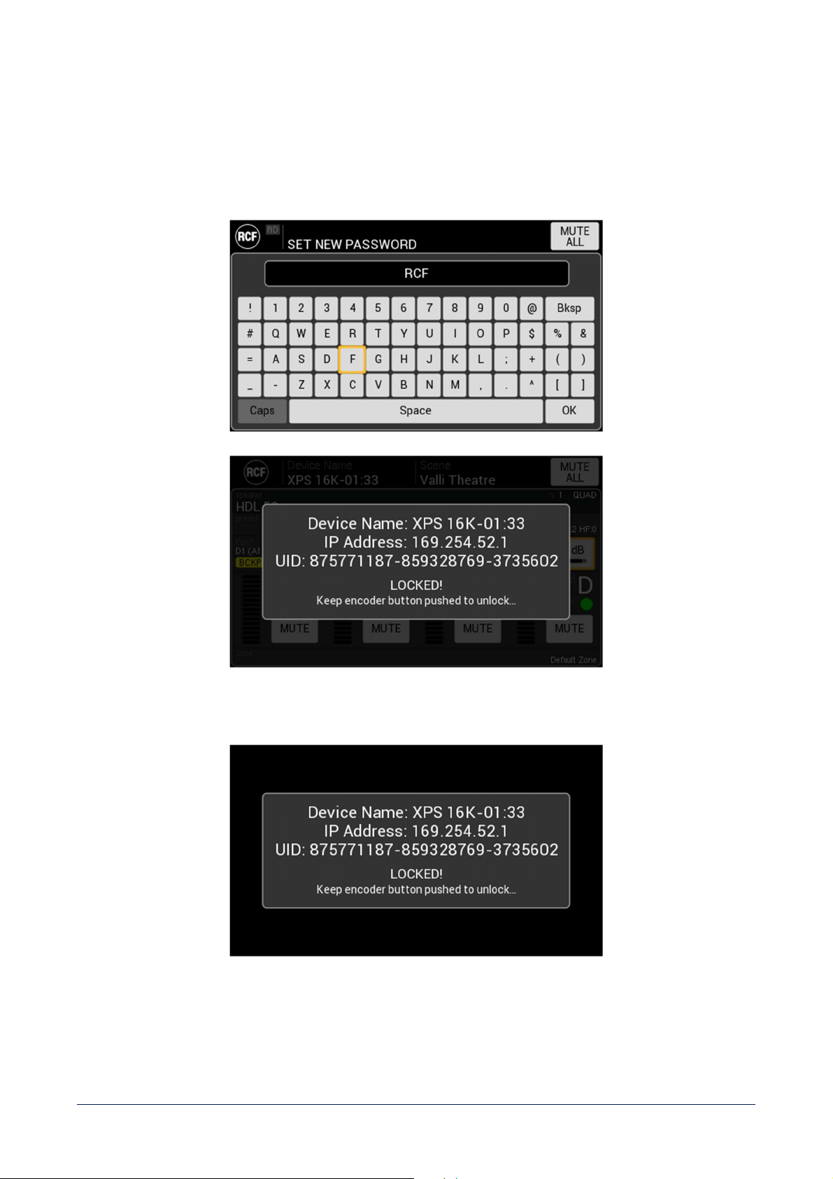
- ENABLE LOCK – activates front panel LOCK function. All front panel elements will be included in the block,
display, buttons and knob. To activate the function, it is required to set a password.
This function is available also when the unit is in the STAND BY status. With a knob short pr
ess it is possible to check if
the LOCK function is active (need knob long press and password) or not (unit can be switched on).
49
Backup & Restore – the FACTORY RESET button set all parameters to factory default value.
SYSTEM INFO
This page shows relevant, read only system information and it is divided into 4 tabs.
GENERAL
- Model.
- Serial number – reporting the device production period (year and month).
- UID – Unique IDentifier.
- Firmware version.
50
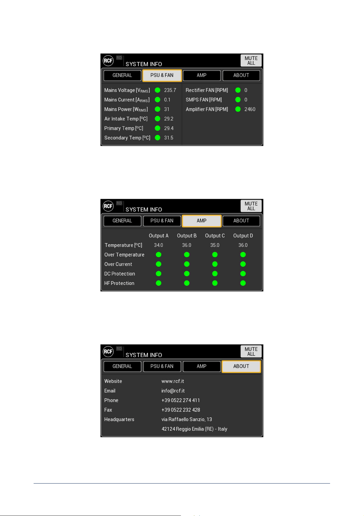
PSU & FAN
Shows the status of device power supply and fans operativity parameters.
AMP
Shows the status of device power amplifiers modules for each output, as well as the protections operativity.
ABOUT
Shows RCF information and contacts.
51
SYSTEM INFO
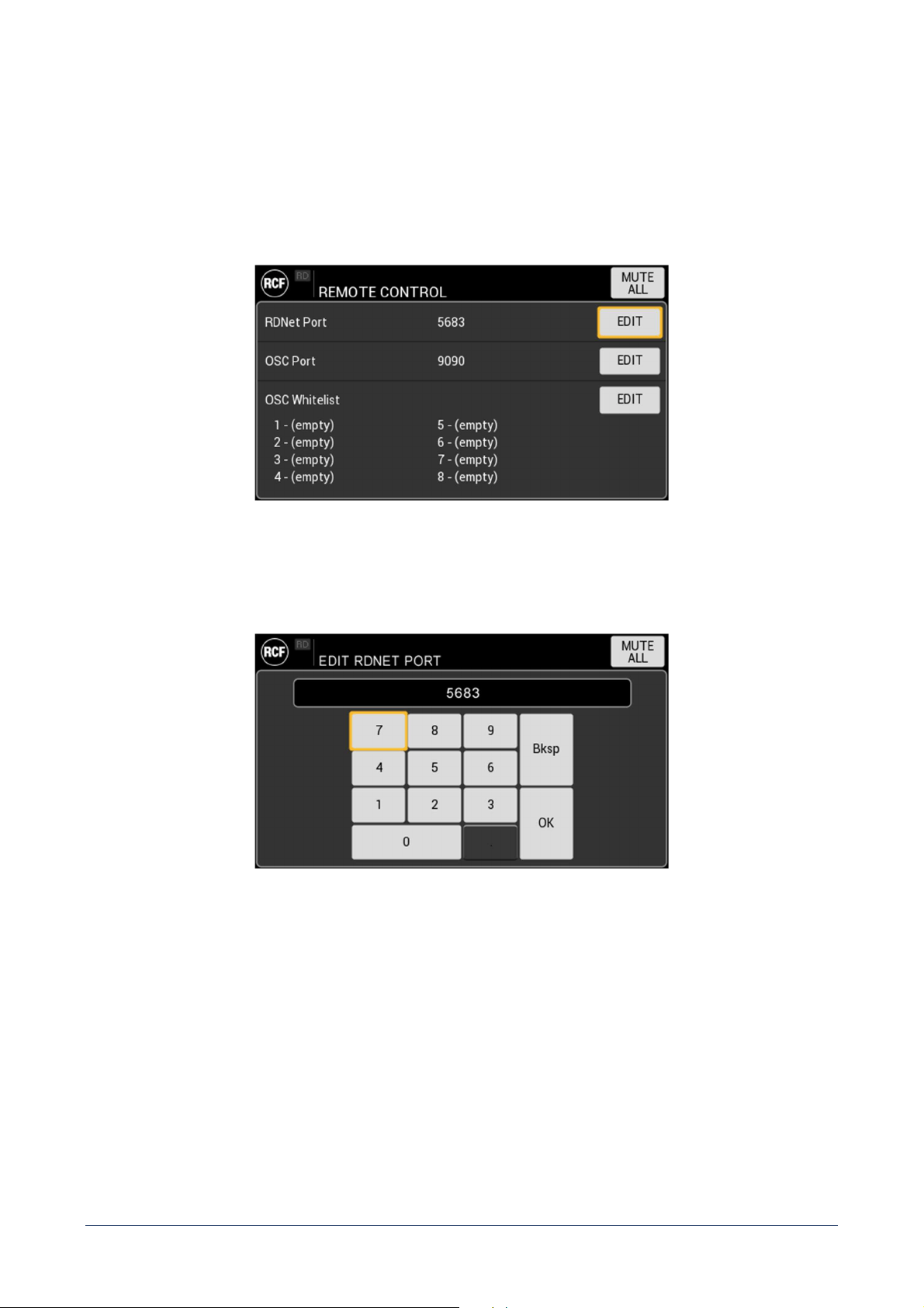
REMOTE CONTROL
This section contains the parameters to be set in order to implement a remote control of the amplifier unit.
RDNet port
It is the UDP port used by RCF proprietary software RDNet for a remote monitoring and control of the unit.
52
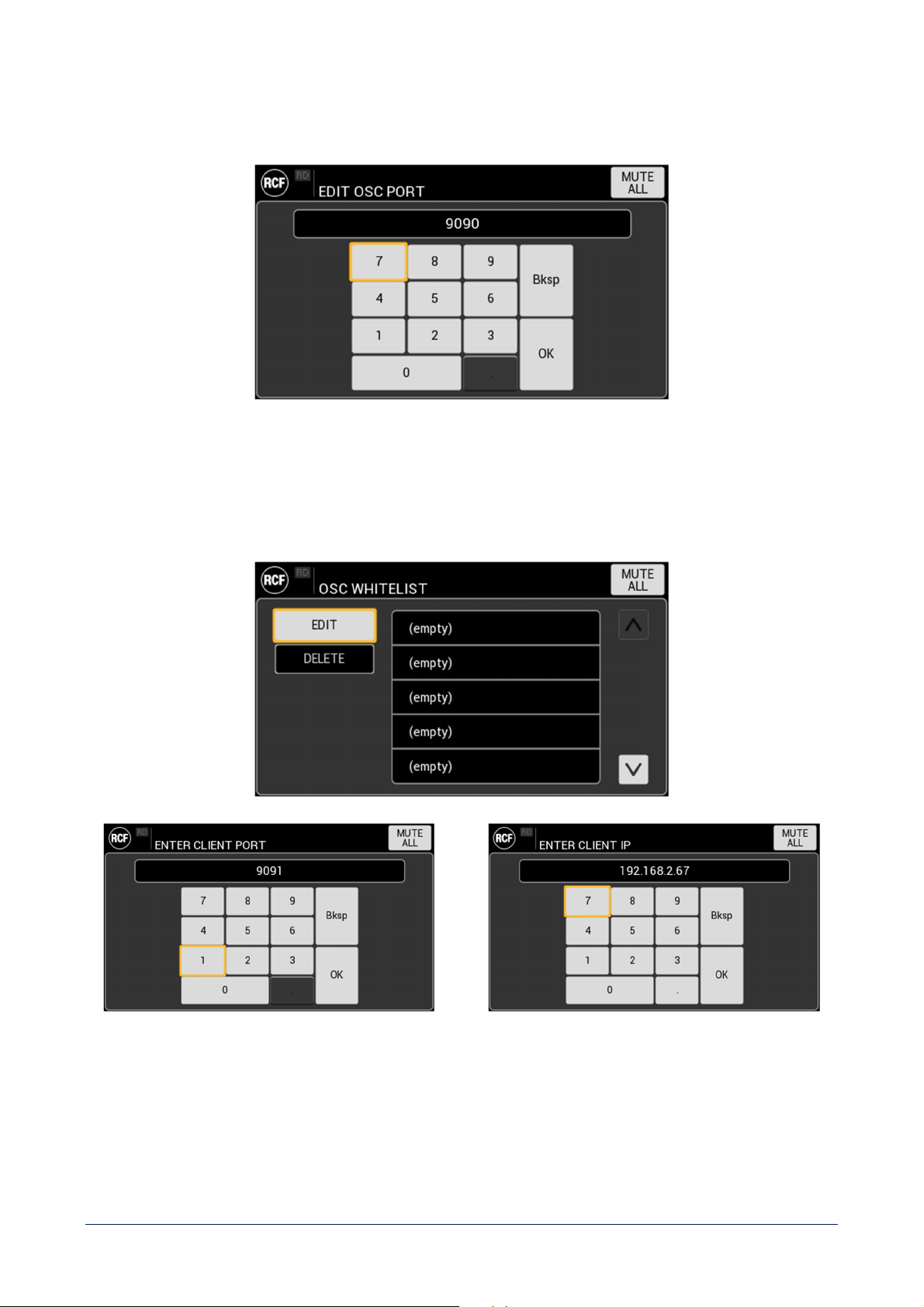
OSC port
It is the UDP port used by the OSC server resident on the amplifier unit.
OSC Whitelist
It is the list of the clients authorized to access the OSC server.
Starting from an empty list, each client shall be added specifying its port and IP address.
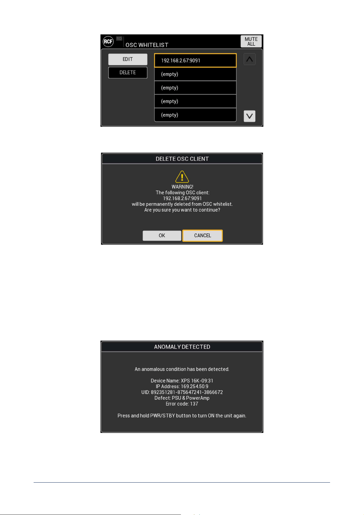
53
Each client can be modified or deleted from the list, after user confirmation.
FAULT SCREENS
These messages will be shown on the display as a consequence of 2 different kind of unit malfunctions.
ANOMALY
An anomaly means that a temporary malfunction has been detected, which is included in the normal unit functional
conditions, for example an overheating condition of all amplifier’s channels.

54
The unit will suggest a soft reset (application reboot) that will be positive as soon as the temporary condition will expire.
FATAL ERROR
A fatal error is an unexpected malfunction that could permanently compromise the unit functioning, for example
a
communication error with power amplifier, that could be due to a modules damage.
The unit will suggest a hard reset (equivalent to a disconnection of the power cord). If it won’t be successful, please
contact RCF service to receive assistance focused on the specific error code.
55
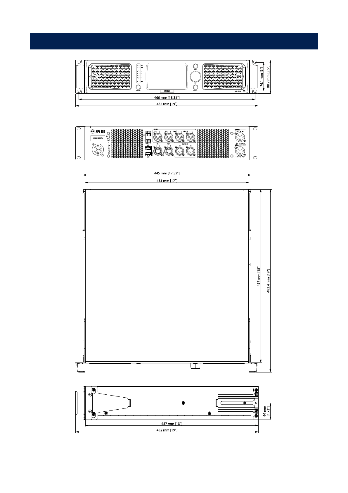
DIMENSIONS

56
TECHNICAL SPECIFICATIONS
Amplifier specifications
Amplifier Class: D
Output power (EIAJ 8:32 all channels driven): 4 x 4000 W @ 2.7 ohm
4 x 2600 W @ 4 ohm
4 x 1400 W @ 8 ohm
Frequency Response (-3dB): 20 Hz ÷ 23000 Hz
SNR (unweighted)
Analog inputs: 111 dB
Digital inputs: 115 dB
Crosstalk: <70 dB
THD+N (20 Hz ÷ 20000 Hz, 1000 W @ 4ohm): <0.2 %
Gain (linear mode @ 0 dB): 32 dB
Damping factor (@ 4 ohm, 20 Hz ÷ 1500 Hz): > 95
Max burst length (@ 50 Hz, CF = 7 dB, 4 ohm, 1% THD+N): 200 ms
Input section
Total number of inputs: 8 / 16 (XPS 16KD)
Line inputs: 4
Line connectors: XLR
Input impedance: 19 kohm (unbalanced)
Maximum input level: +24 dBU
Digital inputs: 4 / 12 (XPS 16KD)
Digital connectors: Ethercon, XLR
Digital type: 4 AES/EBU, 8 DANTE (XPS 16KD)
General Purpose Inputs (GPI): 2
Programmable GPI: Yes
Photo-coupled GPI: Yes
Output section
Signal output number: 4
Signal output connectors: XLR
Power output lines: 4
Power output connectors: Speakon
General Purpose Outputs (GPO): 3
Programmable GPO: Yes
Processing
Digital Signal Processing (DSP): 2 SHARC, 40-bit floating point, 96 kHz
2 ADAU, 32-bit fixed point, 96 kHz
EQ Filters: Peaking, HI/LO-shelving, HI-pass, LO-pass
Advanced algorithms:
FiRPHASE technology, BASS shaper, air compensation, mid-low
correction, driver excursion control, dynamic PEQ, multi-band
compressor, pilot tone & AES detection, backup recovery
strategy, impedance load measurement
Compressors:
RMS limiter, dynamic compressor, power limiter, thermal
compressor
Delay: 0 ÷ 4000 ms (each channel)

57
Configuration and control
Configuration: Front panel touch screen, PC Software
Speakers’ presets: RCF presets library
Control and monitoring protocols: Proprietary OSC based protocol, RDNet
Network: Gigabit ethernet
Protections
Protections:
Forced cooling, short circuit, thermal, DC, Fuses,
VHF (Very High
Frequencies)
Thermal
Temperature range
Continuous operation: -5°C ÷ +40°C / +23°F ÷ +104° F
Reduced output power: -5°C to +50°C / +23°F to +122°F
Fan noise idle: <35 dBA
Fan noise max: <64 dBA
Power supply
Operating voltage: 90-240 V~ 50/60Hz
Nominal current requirements (@ 100-120 V): 30 A
Nominal current requirements (@ 100-120 V): 16 A
Power consumption standby: 20 W
Power consumption idle: 90 W
Power consumption max: 5800 W
Mains fuse: Internal
Standard compliance
Marking: CE, UL
Physical specifications
Cabinet/Case Material: Metal
Handles: 2 metal handles for rack mount
Color: Black
Rack mounting: 19", 2U
Size
Height: 88.7 mm / 3.49 inches
Width: 482 mm / 18.98 inches
Depth: 482.4 mm / 18.99 inches
Weight: 15 kg / 33.07 lbs


RCF S.p.A. Via Raffaello Sanzio, 13 - 42124 Reggio Emilia – Italy 10307699 D
Tel +39 0522 274 411 - Fax +39 0522 232 428 - e-mail: [email protected] - www.rcf.it
