SONAMP MULTI-CHANNEL POWER
AMPLIFIER WITH SonARC V2
INSTRUCTION MANUAL
DSP 2-150 MKII
Sonance DSP2-150 MKII Amplifier
Rear Panel 4/ 2/ 2018
Die Line Do N ot Print
Prints W hite
2-R2-L
IN
OUT
1-R1-L
IN
OUT
1-LEFT
1-RIGHT
DSP 2-150 MKII
IN
OUT
BRIDGE
8 Ω MIN
CLASS 2 WIRING
3-30 VOLTS
AC or DC
VOLTAGE TRIGGER
TCP/IP
DHCP ON-DEFAULT
CAUTION
REPLACE FUSE ONLY WITH
SAME TYPE AND RATING
ATTENTION
REMPLACER UNIQUEMENT AVEC LE
MEME TYPE ET CA LIBRE DU FUSIBLE
IR
CONTROL
IR
STATUS
T5AL/250VAC
IN
OUT
MADE IN CHINA
AC 100-120V ~ 60Hz
AC 220-240V ~ 50Hz
S/N
81 WATTS
CAUTION
RISK OF ELECTRIC SHOCK
DO NOT OPEN
AVIS
RISQUE DE CHOC ELECTRIQUE
NE PAS OUVRIR
1L
1R
DSP 2-150 MKII

TABLE OF CONTENTS
Safety 2
Introduction/Box Contents 3
Front Panel/Rear Panel 4
Amplier Power Requirements 6
Connections & Volume Level Controls 7
Protection Circuitry & LEDs/Stacking 8
Network Connection Instructions 9
Basic Setup 9
Advanced Setup 10
Specications 15
Appendix A & B 16
Troubleshooting 17
Warranty 19
1
IMPORTANT SAFETY INFORMATION
1. Read Instructions — All these safety and operating
instructions should be read before you operate the unit.
2. Retain Instructions — These safety and operating
instructions should be retained for future reference.
3. Heed Warnings — All warnings on the unit and in the
operating instructions should be adhered to.
4. Follow Instructions — All operating and use instructions
should be followed.
5. Water and Moisture — The unit should not be used near
water — for example, near a bathtub, washbowl, kitchen
sink, in a wet basement, or near a swimming pool, etc.
6. Carts and Stands — The unit should be
used only with a cart or stand that is
recommended by the manufacturer.
A unit and cart combination should be
moved with care. Quick stops, excessive
force, and uneven surfaces may cause
the unit and cart combination to overturn.
7. CAUTION: To prevent electric shock, do not use the
subwoofer’s polarized plug with an extension cord,
receptacle, or other outlets unless the blades can be
fully inserted to prevent blade exposure.
8. Ventilation — The unit should be situated so that its
location or position does not interfere with its proper
ventilation. For example, the unit should not be placed in a
built-in installation, such as a bookcase or cabinet, that may
impedetheowofairoverthebackplate.
9. Heat — The unit should be situated away from heat
sources such as radiators, heat registers, stoves, or other
appliances (including other audio components) that
produce heat.
IMPORTANT: READ ALL OF THESE INSTRUCTIONS BEFORE YOU
INSTALL OR OPERATE YOUR SUBWOOFER AND SAVE THESE
INSTRUCTIONS FOR LATER USE.
IMPORTANT: READ ALL OF THESE INSTRUCTIONS BEFORE
YOU INSTALL OR OPERATE YOUR SUBWOOFER, AND SAVE
THESE INSTRUCTIONS FOR LATER USE.
1. Read Instructions — All these safety and operating instruc-
tions should be read before you operate the unit.
2. Retain Instructions — These safety and operating instruc-
tions should be retained for future reference.
3. Heed Warnings — All warnings on the unit and in the oper-
ating instructions should be adhered to.
4. Follow Instructions — All operating and use instructions
should be followed.
5. Water and Moisture — The unit should not be used near
water — for example, near a bathtub, washbowl, kitchen
sink, laundry tub, in a wet basement, or near a swimming
pool, etc.
6. Carts and Stands — The unit should be used only with a
cart or stand tha
t is recommended by the manufacturer.
A unit and cart combination should be moved with care.
Quick stops, excessive force, and uneven surfaces may cause
the unit and cart combination to overturn.
7. CAUTION: To prevent electric shock, do not use the
subwoofer’s polarized plug with an extension cord,
receptacle, or other outlets unless the blades can be
fully inserted to prevent blade exposure.
8. Ventilation — The unit should be situated so that its
location or position does not interfere with its proper
ventilation. For example, the unit should not be situated on
a bed, sofa, rug, or similar surface that may block
the ventilation openings; or be placed in a built-in
installation, such as a bookcase or cabinet, that may impede
th
e flow of air through the ventilation openings.
9. Heat — The unit should be situated away from heat sources
such as radiators, heat registers, stoves, or other
appliances (including other audio components) that
produce heat.
10. Power Sources — The unit should be connected to a power
supply only of the type described in the operating
instructions or as marked on the unit.
11. Grounding or Polarization — Precautions should be taken
so that the grounding or polarization means of the unit is not
defeated.
12. Power Cord Protection — Power cords should be routed so
that they are not likely to be walked on or pinched by items
placed upon or against them, paying particular attention to
cords at plugs, conve
nience receptacles, and the point where
they exit from the controller.
13. Cleaning — The unit should be cleaned only as
recommended by the manufacturer.
14. Non-Use Periods — The power cord of the unit should be
unplugged from the outlet when left unused for a long peri-
od of time.
15. Object and Liquid Entry — Care should be taken so that
objects do not fall and liquids are not spilled into the enclo-
sure through openings.
16. Damage Requiring Service — The unit should be
serviced by qualified service personnel when:
• The power cord or the plug has been damaged.
• Objects have fallen or liquid has been spilled into the unit.
• The unit has been exposed
to rain.
• The unit does not appear to operate normally or exhibits a
marked change in performance.
• The unit has been dropped or the enclosure damaged.
17. Servicing — The user should not attempt to service the unit
beyond that described in the operating instructions.
All other servicing should be referred to qualified service per-
sonnel.
Important Safety Information
The lightning flash with arrowhead
symbol, within an equilateral
triangle, is intended to alert the
user to the presence of uninsulated
dangerous voltage within the
product’s enclosure that may be of
sufficient magnitude to constitute a
risk of electric shock to persons.
The exclamation point within
an equilateral triangle is
intended to alert the user to the
presence of important operat-
ing and maintenance
(servicing) instructions in the
literature accompanying the
appliance.
TO PREVENT FIRE OR SHOCK
HAZARD, DO NOT EXPOSE THIS APPLI-
ANCE TO RAIN OR MOISTURE. THE
APPLIANCE SHALL NOT BE EXPOSED
TO DRIPPING OR SPLASHING. NO
OBJECTS FILLED WITH LIQUIDS SHALL
BE PLACED ON THE APPLIANCE.
TO REDUCE THE RISK OF ELECTRIC
SHOCK, DO NOT REMOVE COVER OR
BACK. NO USER-SERVICEABLE PARTS
INSIDE. REFER SERVICING TO AUTHO-
RIZED SERVICE PERSONNEL.
CAUTION:
10. Power Sources — The unit should be connected to a
power supply only of the type described in the operating
instructions or as marked on the unit.
11. Accessories and Attachments — Only use accessories
andattachmentsspeciedbythemanufacturer.
12. Grounding or Polarization — Precautions should be
taken so that the grounding or polarization means of the
unit is not defeated.
13. Power Cord Protection — Power cords should be routed
so that they are not likely to be walked on or pinched by
items placed upon or against them, paying particular
attention to cords at plugs, convenience receptacles, and
the point where they exit from the controller.
14. Cleaning — The unit should be cleaned only as
recommended by the manufacturer.
15. Non-Use Periods — The power cord of the unit should be
unplugged from the outlet when left unused for a long
period of time.
16. Object and Liquid Entry — Care should be taken so that
objects do not fall and liquids are not spilled into the
enclosure through openings.
17. Damage Requiring Service — The unit should be
servicedbyqualiedservicepersonnelwhen:
• The power cord or the plug has been damaged.
• Objects have fallen or liquid has been spilled into the unit.
• The unit has been exposed to rain.
• The unit does not appear to operate normally or exhibits
a marked change in performance.
• The unit has been dropped or the enclosure damaged.
18. Servicing — The user should not attempt to service the
unit beyond that described in the operating instructions.
Allotherservicingshouldbereferredtoqualied
service personnel.
This device complies with part 15 of the FCC Rules.
Operationissubjecttothefollowingtwoconditions:
(1) This device may not cause harmful interference
(2) This device must accept any interference received,
including interference that may cause
undesired operation.
InaccordancewiththeEuropeanUnionWEEE(WasteElectricalandElectronicEquipment)directiveeective
August 13, 2005, we would like to notify you that this product may contain regulated materials which upon
disposal, according to the WEEE directive, require special reuse and recycling processing. For this reason
Sonance has arranged with our distributors in European Union member nations to collect and recycle this
productatnocosttoyou.Tondyourlocaldistributorpleasecontactthedealerfromwhomyoupurchased
this product. Please note, only this product itself falls under the WEEE directive. When disposing of packaging
and other related shipping materials we encourage you to recycle these items through the normal channels.
DSP 2-150 MKII
Amplier
Tested to comply
with FCC Standards for
homeoroceuseonly.
2
Introduction
Thank you for purchasing the Sonance Sonamp DSP 2-150 MKII
amplier.Whenproperlyinstalled,thisamplierwillgiveyoumany
years of entertainment pleasure. To get the most out of your new
amplier,pleasereadthismanualthoroughlybeforeyou
begin installation.
To achieve the best performance, Sonance recommends that this
amplierbeinstalledbyaSonanceAuthorizedDealer/Installer.
3
Box Contents
(1) Instruction manual
(1) Network connection instructions
(1) Sonamp DSP 2-150 MKII amplier
(1) IEC power cord
(4) Removable rubber feet
(2) Long rack ears
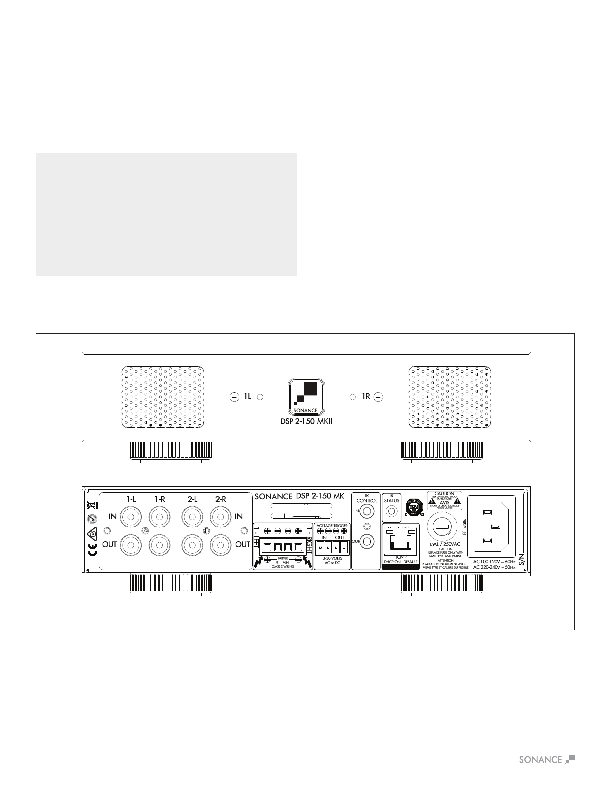
Figure1:SonampDSP2-150MKIIMulti-ChannelPowerAmplier
Unpacking
Save the carton and polystyrene inserts for future safe transport in
casetheamplierismovedorrequiresshippingforrepair.
Before proceeding with installation, locate the serial number on the
rearpaneloftheunitandnoteithereforfuturereference:
S/N:_____________________________________________________.
Placement
Placetheamplieronalevelsurface,inanuprightposition,out
of direct sunlight and away from windows through which rain
mayenter.Situatetheamplierawayfromheatsourcessuchas
hotairductsorradiators.Besurethattheamplierisadequately
ventilated by convection or suitable cabinet fans.
•Neverplaceanyobjectonoragainsttheamplier.
•Neveroperatetheamplieronacarpetedsurfaceasthiswill
compromise ventilation.
•Whentheamplierisinstalledinanycabinet,thefrontorback
must be open during operation. Alternately, install fans in the
cabinet to assure continuous ventilation.

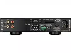
Figure3:SonampDSP2-150MKIIMulti-ChannelPowerAmplierRearPanel
4
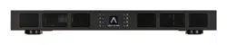
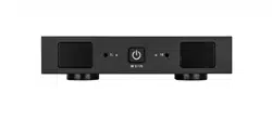
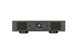
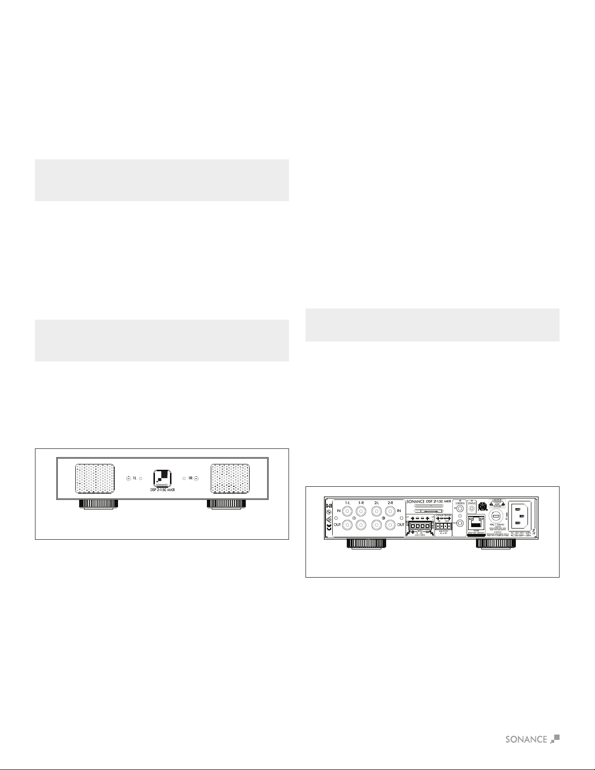
DSP 2-150 MKII Front Panel
1. Illuminated Power Button
2. Power, Active & Protection Indicator LED
3. Recessed Volume Level Control
Figure2:SonampDSP2-150MKIIMulti-ChannelPowerAmplierFrontPanel
1 2 3
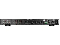
DSP 2-150 MKII Rear Panel
4.AnalogInput/OutCard(L/RLineIn,LoopOutputs)
5. Speaker Block Connector
6.TriggerInput/OutputConnector
7.IRControlIn/Out
8. IR Status Light
9. RJ-45 Input
10. AC Fuse Holder
11. Power Cord Connection
5 9
11
6 7
8 104
NOTE: L/R LINE IN/LOOP OUTPUT CARD CAN BE REPLACED WITH
SONANCE DIGITAL INPUT MODULE (SKU 93099 SOLD SEPARATELY) FOR
ULTIMATE PERFORMANCE ENHANCEMENT THROUGH DIRECT
CONNECTION TO A DIGITAL SOURCE.
5
Input/Output Lights
When each channel is active, the LED will light green as long as a
signalispresent.Input/OutputLEDsblinkingredindicatethatthe
associatedchannelisbeingover-driven.Input/OutputLEDsturning
solidredindicatethattheamplierisinprotectmode.Whilein
protect mode the LED lights will periodically light green to retest the
output to determine if the issue has been resolved. Protect mode
couldbecausedbyashortinthewire,overheatingoftheamplier
orotherinternalproblemwiththeamplier.
Front Panel
Power Button
Thepowerbuttonturnstheamplieronando.WhentheSonance
logo power button is engaged, the power button is illuminated
solidwhite.ThismeanstheamplierhaspowerandisturnedON
and ready to operate. When the Sonance logo button is slightly
dimmed,theamplierisinstandbymode.WhentheSonance
logobuttonblinkswhite,theamplierpowersupplyisinthermal
protection. In this situation, the channel LEDs will also illuminate
red, indicating that the power supply is in thermal protection mode.
NOTE: UPON INITIAL POWER UP, THERE WILL BE A 9-12 SECOND DELAY
BEFORE SOUND IS HEARD DURING THE BOOT UP CYLE. THE INDICATOR
LEDS WILL ILLUMINATE RED, THEN GREEN, THEN GO OUT. THIS IS NORMAL.
NOTE: WHEN ANY OF THE LEDS ARE RED, TURN THE AMPLIFIER OFF
IMMEDIATELY. DETERMINE THE CAUSE OF THE PROBLEM BEFORE
TURNING THE AMPLIFIER BACK ON.
Volume Level Control
Eachchannelontheamplierhasvolumeadjustmentscontrolled
in the SonARC software or on the front panel recessed volume
controls.Outputvolumewillreecttheoptionlastadjusted.The
DSP2-150MKIIampliershipsatthe+12ormaximumvolume
level.
Rear Panel
Line Inputs/Loop Outputs
TheDSP2-150MKIIamplierhaslineinputsandloopoutputs.
Theloopoutputsarenonbuered,themaximumnumberof
ampliersthatcanbeloopedtogetherwilldependontheoutput
capability of your source component
Speaker Connections
TheremovableblockconnectorsusedontheSonampampliers
will accept up to 12 gauge wire. Follow the connection layout on
therearpaneloftheamplier.Makesurenobarewirescomein
contactwiththeamplierchassis.Whenbridgingchannels,usethe
two outside connections on each connector. The positive wire from
the speaker should be on the left side connection and the negative
connection should be on the right side.
CAUTION: FOR CONTINUED PROTECTION AGAINST FIRE, REPLACE THE
FUSE WITH ONLY THE SAME TYPE AND RATING.
Power Cord
The Sonamp DSP 2-150 MKII features a removable power cord.
Plug the female end of the power cord into the Power Cord
Connectorontheamplierrearpanelandplugthemaleendintoa
grounded wall socket.
DONOTplugtheamplier’spowercordintoaconvenienceoutlet
on any other audio or video component. If you need to use an
extension cord, use only a heavy duty (14 GAUGE OR LARGER)
extensioncordtoavoidstarvingtheamplierofthecurrent
necessary for full operation.
Figure4:SonampDSP2-150MKIIAmplierFrontPanelView
Figure5:SonampDSP2-150MKIIAmplierRearPanelView
Auto On - Voltage In/Out Trigger
TheSonampamplierscanbeturnedonandousing3-30volts
AC or DC. The Voltage Output supplies a 12 volt DC signal to
controladditionalampliersorotherequipment.Theincludedred
wire is to prevent the amp from accidentally entering sleep mode
during setup. Remove the red wire when using the voltage trigger.
IR Control
IR control is established via the 3.5mm mono mini input jack on the
rearoftheamplier.IRcommandsincludevolume,mute,group,
powerandinputoptions.IRcontrolsglobalOn/O,groupvolume,
muting and input source selections. Connectivity can be seen with
IR status light.
IP Control
IPcontrolisviatheRJ-45input.IPcontrolspowerOn/O,volume,
muting and input source selections for either global control or
group control.
AC Fuse Holder
To replace the fuse, unplug the power cord from the Power Cord
Connector and use a screwdriver to remove the fuse holder.
DSP 2-150 MKII - 5 amp AC.
Model Input Voltage Output Power (sinewave) Draw Watts
15 Amp Breaker
Qty of Ampliers
20 Amp Breaker
Qty of Ampliers
DSP 2-150 MKII 100-120V AC Full Power All Channels @8 ohms 371 3 5
Full Power All Channels @4 ohms 392 3 4
1/8PowerAllChannels@8ohms 72 20 26
1/8PowerAllChannels@4ohms 74 19 25
@ Idle 17
Sleep Mode 1.5
Voltage or Green Audio 0.48
Model Input Voltage Output Power (sinewave) Draw Watts
13 Amp Breaker
Qty of Ampliers
20 Amp Breaker
Qty of Ampliers
DSP 2-150 MKII 220-240V AC Full Power All Channels @8 ohms 359 4 5
Full Power All Channels @4 ohms 376 3 5
1/8PowerAllChannels@8ohms 69 20 27
1/8PowerAllChannels@4ohms 71 20 27
@ Idle 15
Sleep Mode 1.1
Voltage or Green Audio 0.5
6
Powering the Amplier
The Sonamp DSP 2-150 MKII features a removable IEC power
cord (see Figure 6). A 14 gauge EIA standard 120 volt grounded
powercableisincludedwiththeamplier.Eachtimetheamplier’s
power cord is initially plugged in and the POWER switch is turned
ON,allchanneloutputsaredisconnectedforapproximately9-12
secondsandallPROTECTIONLEDswillilluminatebrieywhilethe
amp boots up.
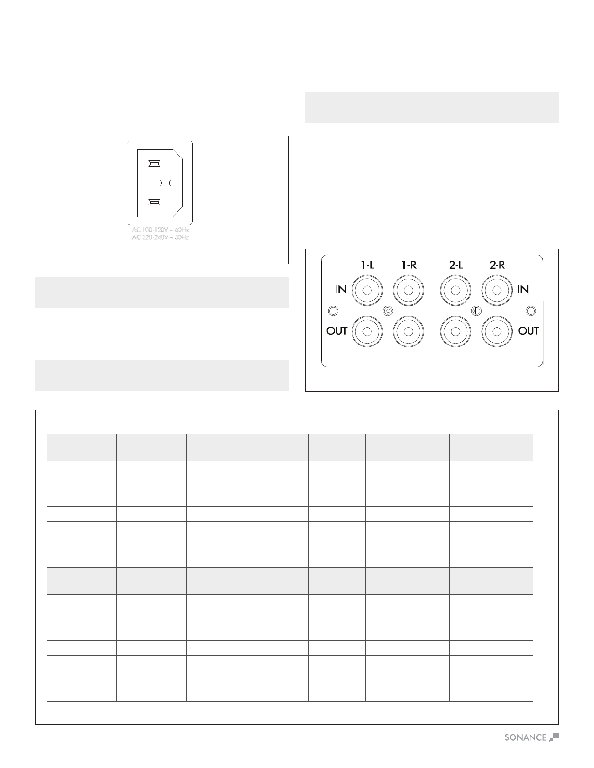
Figure6:IECPowerCordConnection
IMPORTANT: DO NOT PLUG THE POWER CORD INTO THE WALL OUTLET
UNTIL ALL SYSTEM CONNECTIONS HAVE BEEN MADE AND VERIFIED.
Source Connections
Selection DSP 2-150 MKII
There are two options when connecting audio inputs to the
DSP2-150MKIIamplier(seeFigure8):
Primary Line Inputs 1-L, 1-R: Use these inputs for primary
audio source.
Secondary Line Inputs 2-L, 2-R: Use these inputs for a
secondary audio source, paging or a doorbell.
Ampliers Power Requirements:
Figure8:SonampDSP2-150MKIILeft&RightLineInputs
Figure7:SonampDSP2-150MKIIMulti-ChannelAmplierPowerRequirements
IN
O
UT
1-L 1-R
LEVEL LEVEL
B
RIDGE
OFF ON
C
AUTION
RISK OF ELECTRIC SHOCK
D
O NOT OPEN
AVIS
RISQUE DE CHOC ELECTRIQUE
NE P
AS OUVRIR
S/N
T5AL / 250VAC
2-100
AC 100-120V ~ 60Hz
CAUTION
R
EPLACE FUSE ONLY WITH
S
AME TYPE AND RATING
ATTENTION
R
EMPLACER UNIQUEMENT AVEC LE
MEME TYP
E ET CALIBRE DU FUSIBLE
VOLTAGE TRIGGER
IN OUT
AUTO ON
OFF
1 - LEFT
1 - R
IGHT
BRIDGE
CLASS 2 WIRING
VOLTAGE
AUDIO
3-30 VOLTS
AC or DC
8 Ω MIN
AC 220-240V ~ 50Hz
52 watts
Plug the female end of the power cable into the Power Connector
ontheamplier’srearpanelandplugthemaleenddirectlyintoa
grounded 15 amp or 20 amp wall outlet.
IMPORTANT: DO NOT PLUG THE AMPLIFIER’S POWER CORD INTO A
CONVENIENCE OUTLET ON ANY OTHER AUDIO OR VIDEO COMPONENT.
If the electrical service is subject to frequent sags, spikes or
brownouts,apowerconditionerdesignedforusewithhighdelity
equipmentshouldbeemployedtoprotecttheamplier.
CAUTION: FOR CONTINUED PROTECTION AGAINST FIRE, REPLACE THE
FUSE WITH ONLY THE SAME TYPE AND RATING WHEN NECESSARY..

7
Bridging Channels DSP 2-150 MKII
Figure13:VolumeLevelControl
Figure11:BridgingChannels
Volume Level Control
Volume can be controlled from the individual recessed volume level
control screws, located on the front panel and from SonARC (see
Figure 13). These volume controls balance the desired sound levels
perchannel.Volumecanbecontrolledthreedierentwayswith
SonARC v2 (see Figure 14).
1. Output volume 2. Turn on volume 3. Maximum volume
Output volume ranges between -70 to 12. The volume level
controlsaresetat+12bydefault.
Source Connections DSP 2-150 MKII
On the left side of the rear panel are the audio inputs for the left
and right channels. In addition to the left and right inputs there are
also loop outputs for each channel. The loop outputs allow multiple
amplierstosharecommonaudiosources.Theloopoutputson
theampliersarenotbuered.Thenumberofampliersthatcan
be connected in series will depend on the output level of your audio
source.ThesourceconnectedtotheLEFTandRIGHTLINEIN
InputspassthroughtheLEFTandRIGHTLINEOutputs
(see Figure 12).
LEVEL LEVEL
B
RIDGE
OFF ON
MONOSTEREO
12-50
S/N
VOLTAGE TRIGGER
IN OUT
AUTO ON
OFF
IN
O
UT
IN
OUT
1-LEFT 1-RIGHT
LEVEL LEVEL
B
RIDGE
OFF ON
MONOSTEREO
LEVEL LEVEL
B
RIDGE
OFF ON
MONOSTEREO
LEVEL LEVEL
B
RIDGE
OFF ON
MONOSTEREO
LEVEL LEVEL
B
RIDGE
OFF ON
MONOSTEREO
LEVEL LEVEL
B
RIDGE
OFF ON
MONOSTEREO
2-LEFT 2-RIGHT 3-LEFT 3-RIGHT 4-LEFT 4-RIGHT 5-LEFT 5-RIGHT 6-LEFT 6-RIGHT
LOCAL
B
USS A
B
USS B
LOCAL
B
USS A
B
USS B
LOCAL
B
USS A
B
USS B
LOCAL
B
USS A
B
USS B
LOCAL
B
USS A
B
USS B
LOCAL
B
USS A
B
USS B
CAUTION
RISK OF ELECTRIC SHOCK
D
O NOT OPEN
AVIS
RISQUE DE CHOC ELECTRIQUE
NE P
AS OUVRIR
LEFT RIGHT LEFT RIGHT
BUSS INPUT A BUSS INPUT B
1 - LEFT
1 - RIGHT
BRIDGE
8 Ω MIN
CLASS 2 WIRING
T10AL / 250VAC
CAUTION
R
EPLACE FUSE ONLY WITH
SAME TYPE AND RATING
ATTENTION
REMPLACER UNIQUEMENT AVEC LE
M
EME TYPE ET CALIBRE DU FUSIBLE
2 - LEFT
2 - RIGHT
BRIDGE
CLASS 2 WIRING
3 - LEFT
3 - RIGHT
BRIDGE
CLASS 2 WIRING
5 - LEFT
5 - RIGHT
BRIDGE
CLASS 2 WIRING
6 - LEFT
6 - RIGHT
BRIDGE
CLASS 2 WIRING
4 - LEFT
4 - RIGHT
BRIDGE
CLASS 2 WIRING
VOLTAGE
AUDIO
3-30 VOLTS
AC or DC
8 Ω MIN 8 Ω MIN 8 Ω MIN 8 Ω MIN 8 Ω MIN
156 watts
AC 100-120V ~ 60Hz
AC 220-240V ~ 50Hz
Figure14:SonARCPageIn/OutSettingsOutputVolume
Speaker Connections
For the best sound you should use
premium speaker wire that complies
withreratingcodes.Besureto
check local codes governing wire
that may be installed within walls or
ceilings.Sonampampliersare
stable with any reputable brand of
speaker wire or cable. The Sonamp
ampliersusespeakerblock
connectors that can accommodate
up to 12 gauge wire (see Figure 9).
NOTE: ALWAYS CHECK LOCAL BUILDING CODES BEFORE INSTALLING
WIRE IN WALLS OR CEILINGS.
Figure 9
Speaker Connections
Bridging channels is accomplished using the SonARC v2 software.
OnthesecondpageinthesoftwareunderIN/OUTSettings,goto
the output setup area to bridge mode and make your selections
with the drop down buttons.
1.Usetheleftaudioinputwhenoperatingtheampliersoutputin
bridge mode (see Figure 10).
2.SelectONinthebridgemode(seegure10).
3.Connectthespeaker’s“+”leadtotheleftsideoftheconnector
marked“+”(seeFigure11).
4.Connectthespeaker’s“–”leadtotherightsideoftheconnector
marked“+”(seeFigure11).
5. Connect the line level audio input to the LEFT channel input on
theamplier.
IMPORTANT: THE MINIMUM SPEAKER IMPEDANCE FOR BRIDGED
OPERATION IS 8 OHMS. DO NOT OPERATE A ZONE IN THE BRIDGED MODE
INTO A SPEAKER THAT IS LESS THAN 8 OHMS NOMINAL IMPEDANCE.
Figure10:BridgingChannels
Figure12:SonampDSP2-150MKII
LeftandRightLineInputs/Outputs
IMPORTANT: USE CAUTION WHEN SETTING VOLUME LEVELS EITHER ON
THE AMPLIFIER OR AN AUDIO SWITCHER AS NOT TO OVERDRIVE AND
POSSIBLY DAMAGE SPEAKERS. VERIFY ALL SOURCES AS OUTPUT
VOLTAGE VARIES FROM DEVICE TO DEVICE.

8
IMPORTANT: ALLOWING THE AMPLIFIER TO OPERATE WITH ONE OR
MORE CHANNELS IN PROTECT MODE FOR AN EXTENDED PERIOD OF
TIME CAN DAMAGE THE AMPLIFIER.
Protection Circuitry and LEDs
TheSonampampliershaveamulti-stageprotectionsystemto
preventdamagetoyouramplierandspeakers.
Amplier Channel Protection DSP 2-150 MKII
If a channel encounters a short-circuit (in bridge mode the
protection circuitry will sense a short circuit across both positive
speaker terminals), or extremely low impedance will cause the
aectedchanneloutputstoautomaticallymute.Theoutputof
theaectedchannelwillremainmuteduntilthefaulthasbeen
corrected.Onlytheaectedchannelsoutputwillmute,allother
channels will continue to operate normally.
Amplier Channel Protection Indication DSP 2-150 MKII
OnthefrontpaneloftheSonampDSP2-150MKIIampliersare
dual color LEDs that illuminate to indicate the current operating
statusofeachamplierchannel.
When the LED blinks red this is an indication that the channel is
being over driven.
WhentheLEDlightsaresolidredthisisanindicationtheamplier
is in protect mode. While in protect mode the LED lights will
periodically light green to retest the output to determine if the short
has been removed. Protect mode could be caused by a short in
thewire,overheatingoftheamplierorpossiblyaninternalproblem
withtheamplier.
Iftheampliersensesaverylowimpedanceorashortonits
outputs, then it will mute its output and the protection LEDs will
turn red. The output will remain muted until the fault is cleared.
Check the rear panel block connector for shorted wire strands
or reduce the number of speakers connected in parallel to the
amplieroutputs.Sonanceampliersareratedfora4ohmloador
higher, such as two pair of eight ohm speakers.
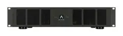
Rack Ear Installation DSP 2-150 MKII
The DSP 2-150 MKII ships with two long rack ears for when the
amplieristobeusedaloneina1Uspace.Unscrewthefour
Phillips head screws (M4 x 0.7 pitch x 10mm long) found on each
sideoftheleftandrightforwardsectionofamplier.Usethese
screwstoconnecttheincludedrackearstotheamplier
(see Figure 15).
MKII
Figure15:RackEarInstallationDSP2-150MKII
Side View Right
Front View
Amplier Stacking
The DSP 2-150 MKII is capable of being directly stacked with the
feet removed for use in low to moderate output applications (see
Figure 16). For high-output applications, it is recommended to leave
atleast1Uspacebetweenampliersforincreasedventilation.
Itisnotrecommendedtostackmorethanthreeampliershigh
without spacing.
To place two Sonamp 2-100 or DSP 2-150 MKII in a single rack
unitorder:RackMountBracketforSonamp2-100&DSP2-150
MKII SKU# 93098 (see Figure 17).
MKII
MKII
MKII
1L 1R
2-100
MKII
Figure16:StackedCongurationDSP2-150MKIIx3
Figure17:RackMountBracketfor2-100&DSP2-150MKII
IMPORTANT: ANY TIME THE PROTECTION CIRCUITS ARE TRIGGERED,
UNPLUG THE AMPLIFIER’S POWER CORD FROM THE WALL OUTLET
BEFORE TROUBLESHOOTING.
Amplier Power Supply Protection DSP 2-150 MKII
Theamplieralsohasprotectionforthepowersupply.Ifthepower
supply heat sink temperature exceeds the design maximum, the
protection circuit will activate, disconnecting all channel outputs.
This is indicated by a blinking light on the front panel power switch.
NOTE: IF SHELF MOUNTING, ATTACH THE FOUR INCLUDED FEET BY
SCREWING THEM INTO THE THREADED OPENINGS ON THE BOTTOM
CHASSIS. NO TOOL IS REQUIRED.
Front View
Front View
9
Connecting to Your SonARC Homepage
1.Theamplier’sfactorydefaultsettingshasDHCPsettoON.
2.Connecttheampliertoanetworkwitharouter.Makesurethe
computerandamplierareonthesamenetwork.
3.Turnontheamplier.
4.TheamplierwillbeissuedanIPaddressbytherouter.
5. Use an IP scanner to determine the IP address of the Sonance
DSPamplieronthenetwork.WerecommendFingapp
for IOS, Advanced IP Scanner for Windows devices and
LanScan for macOS.
6.Networkdeviceswillshowupandtheamplierwillbe
named Sonance.
7. Open Safari or Chrome.
8. In the URL address window at the top, enter the IP address of
theSonanceDSPampliertocongure.
SonARC Software
Network Connection Instructions
SonARC Legend
Toggle/
Pull-down Menu Free Type Field Single Action Menu
Equipment List
(1) Computer or tablet
(1) Network router with DHCP service enabled
(2) RJ-45 cables (one when using wireless)
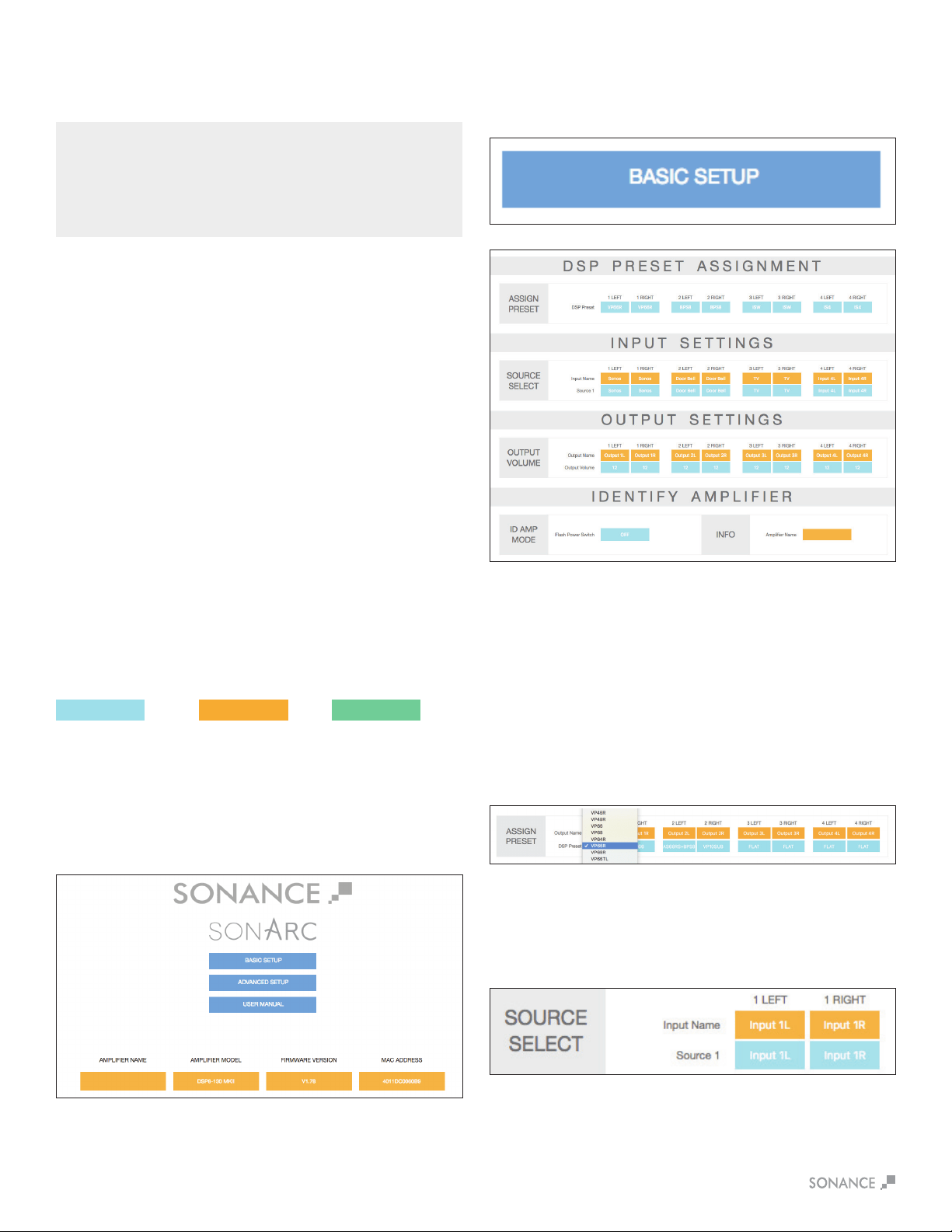
SonARC Homepage
Setup Options
YourSonARCHomepagewillhavetwooptionsforsetup:Basic
SetupandAdvancedSetup.Ampliernamecanbeenteredby
the installer.
Basic Setup Page
This page is for basic setup of EQ, source and volume. To start,
click on the Basic Setup button.
DSP Preset Assignment
Assign Preset
Click on the individual channels to show the drop down menu
of preset options. Once you locate the preset for your Sonance
speakers click on the name to set the preset. Each Sonance
DSPamplierhas50slotswithpre-conguredDSPcurvesfor
Sonance speaker models pre-loaded. If the speaker model in your
applicationisnotonthepre-loadedlist,hundredsofDSPlesare
available for download from the Sonance website. Download the
presetleforadditionalSonancespeakermodelsat:
www.sonance.com/electronics/ampliers/dsp.
Input Source
This pull down menu allows you to select which input you would
like to assign to the channel.
Input Settings/Source Select
Input Name
Thisisauserenteredeldwithamaximumof15characters.
Usetheseeldstodescribethetypeofinputconnected.
10
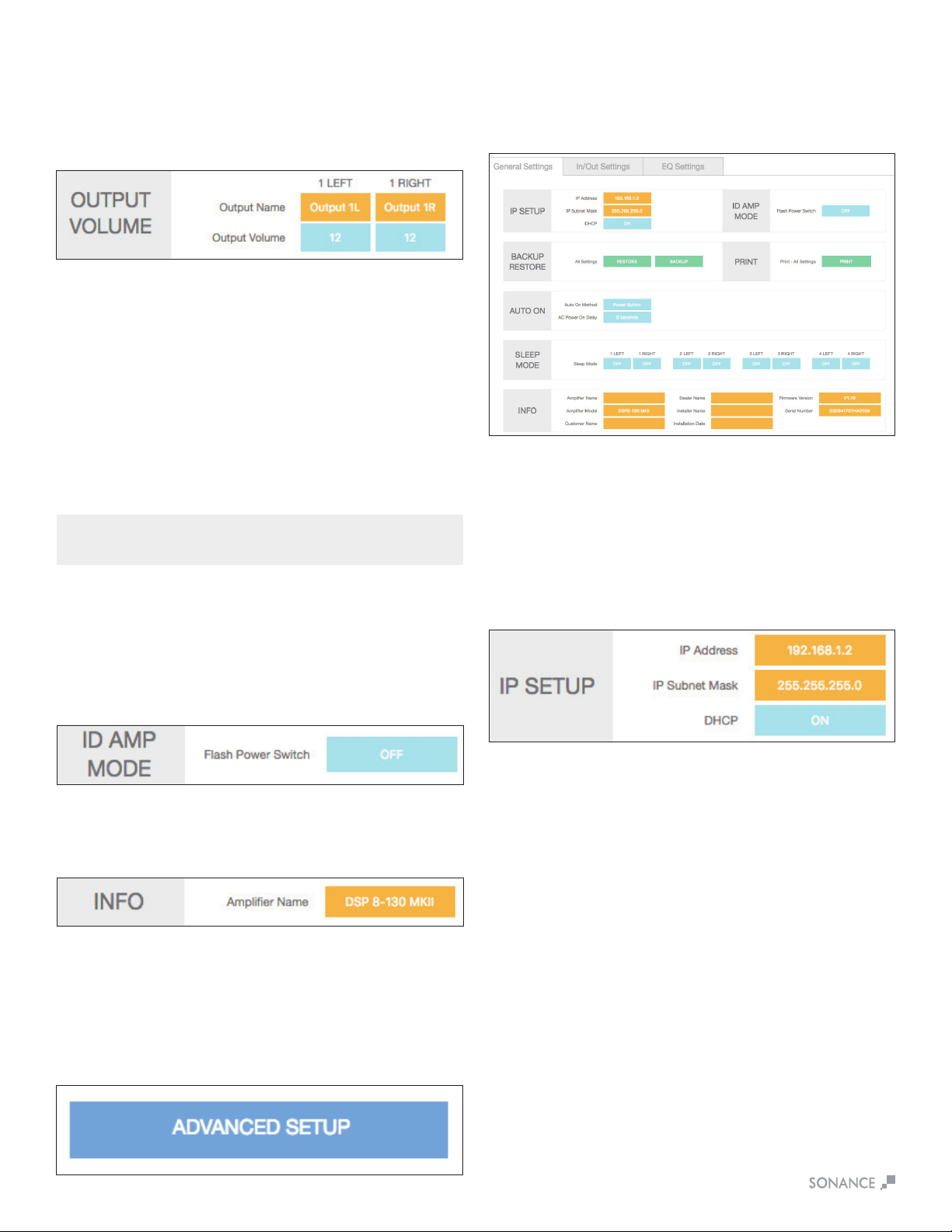
Output Volume (Basic Set-Up)
Play music with wide dynamics and bass that will stress
the system.
1. Start with the Output Volume for both 1L and 1R set at -30.
2. Slowly increase the volume up towards 12 and listen for
any distortion or strain from the speakers. When you hear any
distortion, reduce the volume 1 or 2 steps below this value.
3. Set this volume number for both channels. This will provide
maximum system performance and protect the speakers from
beingdamagedbyamplierclippingandover-excursionof
the woofers.
Advanced Setup Page
This page in SonARC allows you to make advanced changes to
theyouramplierssettingsandconguration.Tostartclickonthe
AdvancedSetupbuttonfromyourMKII’shomepage.
IP Setup
DHCP On/O
DHCPON/OFFistherstoptioninIPSETUP.AllSonanceDSP
seriesampliersshipwithDHCP(DynamicHostConnection
Protocol)ON.InmostinstallationsDHCPshouldbeleftON
except when you are using a control system for IP control. If you
arecontrollingtheDSPseriesamplierusingIP,thenwesuggest
you turn DHCP OFF and use a static IP address.
The basic setup is complete!
NOTE: LEFT AND RIGHT CHANNELS ARE LINKED. OUTPUT VOLUME IS
LINKED TO TURN ON VOLUME IN BASIC SETUP.
Identify Amplier
ID Amp Mode
WhenthepowerswitchisturnedON,thepowerbuttononthe
frontoftheamplierwillashtoindicatewhichamplieryouare
programming.Thiswillmaketheampliereasytoidentifyina
multipleamplierinstallation.
Info
Thisisauserenteredeldwithamaximumof15characters.
Use this area to name your MKII.
General Settings Tab
The Advanced Setup automatically starts out on the General
Settings tab. This tab is used to set up your MKII with a network
network connection, auto on method and other basic information.t
Output Settings/Output Volume
Output Name
Thisisauserenteredeldwithamaximumof15characters.
Usetheseeldstodescribetheroomorareathechannelwill
be powering.
IP Address
The second setting in the IP SETUP section is the IP address.
WhenDHCPisONthecurrentIPaddresswillbedisplayed.
To change the IP address DHCP must be set to OFF.
WhenDHCPisturnedotheIPaddressthattherouterassigned
totheamplierwillstillbeapplied.ThisIPaddressisagoodplace
to start since it is not being used by another network device. If you
wish to change the IP address you should perform a scan of the
network and only assign an unused IP address within the range of
your router. As a general rule only change the last three digits of
theIPaddressintheampliersettingsandonlyassignnumbers
between 2 and 254. Following this suggestion will minimize the
chanceofmakingtheamplierinaccessible.
It is critical to type in the correct IP address. If the wrong IP address
isentered,theampliercouldbecomeinaccessible.Makechanges
to the IP settings only if you fully understand network setup.
Resetting DHCP
If the IP address is not known and the amp is locked out, use the
DHCP Reset method in Appendix A.

11
Auto On
Select the Auto On method you would like to use with the blue pull
down menu. During setup it is strongly recommended that you
keeptheAutoOnmethodsettoPOWERBUTTONtopreventthe
amplierfromshuttingo.YoucanreturnatanytimetotheAutoOn
settingandselectthenalmethodofAutoOnforyourinstallation.
WhencontrollingtheamplierusingIPandIRcommandswe
suggest using the Power Button Auto On mode. See Appendix B.
Audio
In the Audio Auto On mode, there are three sleep mode options
(o,15minutes,3hours).Eachchannelhasanindependentsleep
mode setting. The sleep mode is triggered by an audio sensing
circuitoneachchanneloftheamplier.Theminimuminputsensing
level is 0.5mV.
Audio Green
IntheAudioAutoOnmodetheamplierwillpoweroafter15
minutes without an audio signal present on any of the channels.
Whenanaudiosignalisappliedtheamplierwilltakeapproximately
9-12secondsfortheampliertoreproduceaudioaftergoing
throughitspowerupsequence.IntheaudioAutoONmodethe
sleep function is active, see sleep mode note below. This mode
complies with EU energy saving standards.
Backup Restore
The green BACKUP and RESTORE buttons take all of the settings
oftheamplierincludingtheDSPsettingsandencapsulatesthem
intoonele.Thisallowsyoutotransferthesesettingsintoanother
ampofthesamemodelwiththesamermwareversion.Thisisa
proprietaryletype(.binle),agnostictoPCorMac.
Print
The print button will output a complete list of all settings for the
amplier.Itisalwaysagoodideatokeepabackuphardcopyof
the settings for each installation.
Power Button
When sleep mode is set to OFF the channel will be on at all times.
Use the sleep mode OFF setting for audio signals like a doorbell or
paging where audio must be reproduced immediately at any time.
Voltage
IntheVoltageAutoOnmode,theamplierwillpowero
immediately when the trigger voltage has been removed. When a
3-30VACorDCvoltageissenttotheamplier,itwilltake6-8
secondsfortheampliertoreproduceaudioaftergoingthroughits
power up sequence. This mode complies with EU energy
saving standards.
Voltage Green
IntheVoltageGreenAutoOnmodetheamplierwillpowero
immediately when the trigger voltage has been removed. When a
3-30VACorDCvoltageissenttotheamplieritwilltake6-8
secondsfortheampliertoreproduceaudioaftergoingthrough
its power up sequence. In Voltage Green mode the Ethernet
connectionisnotactivewhentheamplieriso!Thismode
complies with EU energy saving standards.
IP Subnet Mask
The third setting in the IP SETUP section is the IP Subnet Mask.
This is an advanced network setup function. Under most
circumstancesthiseldshouldnotneedtobeedited.
Makingchangesinthiseldshouldonlybedonebyanexperienced
network administrator.
ID Amp Mode
WhenthepowerswitchisturnedON,thepowerbuttononthe
frontoftheamplierwillashtoindicatewhichamplieryouare
programming.Thiswillmaketheampliereasytoidentifyinamulti-
amp installation.
Sleep Mode
Sleepmodeallowsyoutoselecthowlongtheamplierwillstay
activeaftertheAutoONmethodceases.
O
When set in the OFF mode the channel will be on at all times.
Use the OFF setting for audio signals like a doorbell or paging
where audio must be reproduced immediately at any time.
After 15 Minutes
When an audio signal has not been present on a channel for 15
minutes, the channel will go to sleep. From the sleep state the
channel will take approximately 2-3 seconds to reproduce audio
again. This mode is similar to legacy Sonamp Auto-On operation.
After 3 Hours
When an audio signal has not been present on a channel for
3 hours, the channel will go to sleep. From the sleep state the
channel will take approximately 2-3 seconds to reproduce audio
again when audio is detected.. This mode works well for home
theater installations.
Info
Theorangeblocksareinstallerentereddata.Eacheldhasa
maximum of 15 characters.
NOTE: WHEN AUDIO GREEN MODE IS ENABLED AND THE AMPLIFIER IS
ASLEEP, IP COMMANDS CANNOT BE RECEIVED.
12
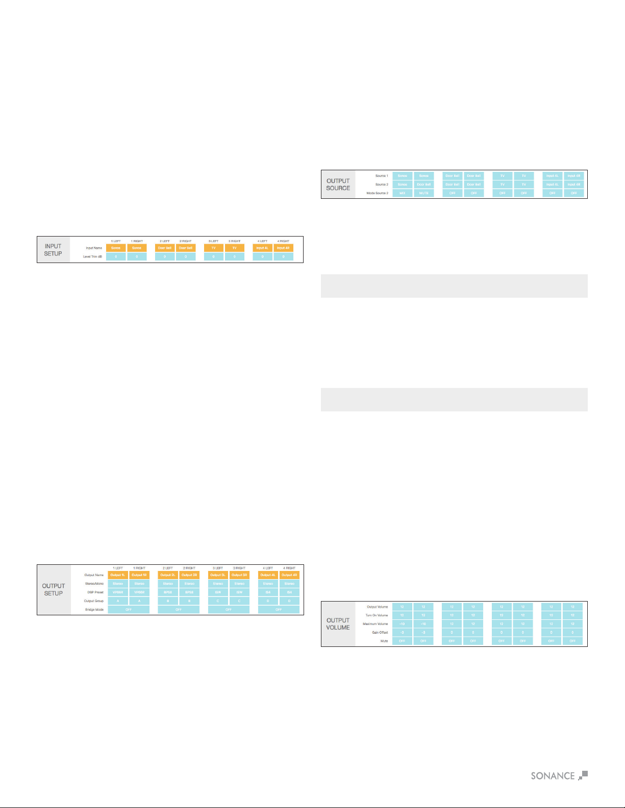
In/Out Settings Tab
TheIN/OUTsettingstabisusedtoassignyourMKII’sinputand
outputspecications.
Input Setup
Input Name
Thisisauserenteredeldwithamaximumof15characters.
Usetheseeldstodescribethetypeofinputconnected.
Input Trim dB
Thispulldownmenuallowsforinputlevelstobeadjusted+/-6dB.
This gives you the ability to level out all your inputs so when you
switch from input to input the levels will be equal. This can eliminate
anyharshtransitionsbetweensourceswithdierentoutput
voltages. Select the pull down menu in each channel to adjust the
level trim between plus or minus 6dB in increments of 0.5dB.
Output Setup
Output Name
Thisisauserenteredeldwithamaximumof15characters.
Usetheseeldstodescribethelocationofthespeakers.
Stereo/Mono
Allows each channel to be set for Stereo or Mono operation.
When Mono is selected, the Left and Right of the input selected will
be combined to create Mono.
DSP Preset
Apply any of the available Sonance DSP presets to each channel of
theamplierindependently.Youcanapplyanyopenpreset&then
makemodicationsontheEQsettingspage.
Output Group
TheDSP2-150MKIIhaseightoutputgroupoptions:A-H.
WhenusingIPorIRtocontroltheamplier,commandsaresentto
anoutputgroupandnottoaspecicchannel.
Bridge Mode
When more power is required, two channels can be bridged.
Follow the instructions on page 5, in the software, for connecting
thewiresthenselectBridgeON.
Output Source
Source 1
This is the primary source you will direct to the speakers. Any of the
inputsavailableontheampliercanbeselected.Whenchannels
are in the same output group, the inputs will all change in unison.
Left inputs default to left outputs and right inputs to right outputs.
Source 2
This is a secondary source that based on the mode Source 2
setting described below, will either override or mix with Source 1.
This input could be used for a doorbell or paging for example.
Mode Source 2 O
WhensettoOFF,Source2hasnoeectontheoperationof
the channel.
Mix
When set to MIX, Source 1 and Source 2 will be blended together
when a signal is present on Source 2.
Mute
When set to MUTE, Source 1 will be muted while Source 2
is active.
Output Volume
This is the main volume level control for each channel.
When channels are placed in the same output group the levels will
change simultaneously.
Maximum Volume
IP or IR can be used to limit how loud the speakers will play in
certain areas. Output Volume and Turn On Volume can never
exceed the Maximum Volume. Maximum Volume is the highest
volumelevelthattheamplierwilloutput.Theoutputgroup
selecteddoesnotaectthissetting.
Gain Oset
Thegainosetsettingallowschannelsinthesameoutputgroup
tohavetheirlevelsadjustedindependentlyby+/-6dB.Thisisan
independentsettingnotaectedbytheoutputgroup.
Mute
The mute setting eliminates the output from the speakers.
Channels placed in the same output group will
change simultaneously.
NOTE: FRONT PANEL VOLUME CONTROLS OVERWRITE THIS SETTING.
Turn On Volume
Thisdetermineswhatvolumeleveltheamplierwilldefaultto
when it is turned on. Channels placed in the same output group
will automatically have identical levels. Turn on volume level is
implementedwhentheamplieristurnedowiththepowerswitch
or goes into sleep mode.
NOTE: FRONT PANEL VOLUME CONTROLS OVERWRITE THIS SETTING.
EQ Setting Tab
The EQ settings tab is used to assign your DSP EQ presets for
each channel. EQ presets provide best possible audio quality for
most Sonance speakers. EQ presets are available at
http://www.sonance.com/electronics/ampliers/dsp.

13
Test Signal
The SonARC software includes a built in pink noise generator.
The pink noise signal can be used in conjunction with a real time
analyzer to measure speakers.
Test Signal Select
You have the option of pink noise or test signals fed into line level
inputs. Use the blue pull down menu to select between pink noise
or line level inputs as a source for the test signal.
Volume
Select your desired volume.
On/O
Togglebetweenonando.Thepinknoisesignalshouldnotbeleft
on for more than 10 minutes to minimize the risk of damaging
the speakers.
NOTE: THE PINK NOISE GENERATOR IS AFTER THE AUDIO SENSORY
CIRCUIT SO THE AMP WILL GO TO SLEEP DEPENDING ON THE AUTO ON
MODE SELECTED. IF THE PINK NOISE STOPS, POWER CYCLE THE AMP.
DSP Preset Editor
Select Preset or Edit
This section allows you to edit any of the 50 existing presets.
Select the preset you want to edit from the drop down menu.
Edit Name
Edit the name of your preset with up to 15 characters.
Delete Settings
The Reset button deletes the selected preset.
Assign Preset
Output Name
These can be named Output 1L & Output 1R or room names such
as Kitchen L and Kitchen R. These are a duplicate of the output
nameontheIN/OUTsettingspage.
DSP Preset
Select your DSP preset with the blue pull down menu. This will auto
populateintheIN/OUTsettingspage.
Import Export
All Presets
The green IMPORT EXPORT buttons allow you to save all 50
presetsinonele.Thisoptioncanbeusefulwhensettingup
multipleampliers.
Single Preset
The green IMPORT EXPORT buttons allow you to import or export
presets individually.
Import Single Preset
1. Import speaker preset to a location on your computer. This can
be accomplished by saving a DSP preset downloaded from
Sonance website.
2. Select the location you would like to store the new preset using
the SELECT PRESET TO EDIT pull down menu. You can save
the new preset in any of the open preset locations or you can
overwrite an existing preset you do not need.
3. Press the green IMPORT button.
4. From the pop-up menu choose local or internet.
5. You will be directed to My Computer (Windows) or Finder (MAC).
6. Find & select the new preset you would like to import (eqs).
7. You will be directed to a screen that says upload successful.
8.Press“ClickHereToGoBack”.
9. The preset will now be saved in the location you selected.
NOTE: PRESETS DOWNLOADED FROM INTERNET CAN TAKE UP TO 15
SECONDS TO DOWNLOAD.
Copy Preset
From/Tothebluepulldownmenusallowyoutopullapresetfrom
one location and assign it to another location. Press green copy
button to activate.
Export Single Preset
1. Use the blue pull down menu SELECT PRESET to edit
located above the IMPORT EXPORT green buttons.
2. Select the preset you choose to export from the pull
down menu.
3. Press the green EXPORT button. Depending on your
webbrowser,theexportedlewillbesavedinyour
downloads folder or you will be prompted where you
wouldliketosavethele.
Output Frequency Response
Thisgraphreectsthechangesmadebelow.
TheEQimageshowsEQ4ONat500Hz,theQissetto3witha
-6dB gain, creating a gradual dip in the lower midrange.
EQ9showsONat3000Hz,theQissetto10witha-6dBgain,
creating a sharp dip in the midrange.
EQ10showsONat10000Hz,theQissetto1witha+4dBgain,
creating a very gradual slope in the high frequencies.

14
Parametric EQ
AllSonanceDSPampliermodelsfeaturea10bandparametric
EQ. Adjustments made to the EQ will be displayed on the output
frequency response graph. We strongly suggest not adjusting the
EQ without proper measurement equipment.
EQ On/O
Turnseachofthe10parametricEQltersonando.
EQ Frequency Hz
Enterthecenterfrequency(20Hz-20kHz)forthelterto
be adjusted.
EQ-Q
This setting determines the width of the adjustment range.
The lower the number the wider the bandwidth. The higher the
number the narrower the bandwidth.
EQ-Gain +/- dB
Thelevelofeachparametricadjustmentcanbeset+/-12dB.
Careful adjustment of the EQ gain is necessary to prevent damage
to the speakers. Always increase the level as little as possible.
Therstchoiceshouldalwaysbetoreducetheoutputtoachieve
the target frequency response.
Delay
Delay is shown in milliseconds, feet and meters. You can make an
entryinanyofthethreeeldsandtheothereldswillbecalculated
automatically. The minimum delay is .01 milliseconds, the maximum
delay is 12 milliseconds. This function is useful when compensating
for distance between satellites and subwoofers for instance.
Tilt Control
The tilt controls are very sophisticated bass and treble control.
By selecting a start frequency and level you can ramp the bass and
ortrebleupordown.Theeectofthetiltcontrolisvisibleinthe
output frequency response graph.
Low Tilt/High Tilt
Thissettingturnsthelowandhightiltcontrolsonando.
Frequency
Enter the start frequency of the tilt in Hz. To boost the low
frequencies you would typically set the low tilt to 100Hz. To boost
the high frequencies you would set the high tilt to around 5kHz.
Gain
Thegaincanbesetin1dBsteps+/-12dB.Whensettingthegain
use as little positive gain as possible to minimize the risk of damage
to the loudspeakers.
Crossover
LP Xover / HP Xover
Thissettingturnsthehighandlowpasscrossoversonando.
Frequency
Inthiseldyoucanenteranyfrequencybetween20Hz-20kHz.
Filter Type
6dB,12dB,18dBand24dBperoctaveButterworthltersare
available in the pull down menu. The higher the number the faster
the speakers output will be reduced below or above the crossover
frequency. In a typical satellite subwoofer system the crossover
frequency would be around 80-100Hz for both the high and low
passlters.
All of the above output power ratings are when connected to an 8
Ohm load.
No Limiter -3dB -6dB -9dB
MKII
150 watts 75 watts 37.5 watts 18.25 watts
Limiter
The limiter operates as a brick wall limit on the output of the
amplier.Thelimiterdropdownmenuhas-3dB,-6dBand-12dB
options.Themaximumoutputsforeachofthemodels:
15
Specications
SONAMP DSP 2-150 MKII
NumberofChannels 2 (1 stereo pair)
Power Output - 8 ohms (Stereo) 150 Watts RMS per channel (all channels driven)
Power Output - 4 ohms (Stereo) 224 Watts RMS per channel (all channels driven)
Power Output - 8 ohms (Bridged) 473 Watts
FrequencyResponse 5Hz–50kHz,bandwidthlimited
Total Harmonic Distortion 0.07% (1kHz, 8 ohms) 0.06% (1kHz, 4 ohms)
SignaltoNoiseRatio -100dB(20Hz-20kHz)
Input Gain 29dB
Input Sensitivity 100mV for 1 Watt Output @8 ohms
1230mV for 150 Watts Output @8 ohms
Input Impedance 20k ohms
Loop Output Impedance 600 ohms
Maximum Source Input Voltage 2.9V VAC RMS
CommunicationProtocol TCP/IP(RJ-4510/100BaseT)
Power Consumption 120V AC
@8 ohms (sinewave, full power) 371 Watts (all channels driven)
@4 ohms (sinewave, full power) 392 Watts (all channels driven)
@8ohms(sinewave,1/8power) 72Watts(allchannelsdriven)
@4ohms(sinewave,1/8power) 74Watts(allchannelsdriven)
@Idle 17 Watts
@IP or IR standby 1.5 Watts
@Standby 0.48 Watts
Power Consumption 220V AC
@8 ohms (sinewave, full power) 359 Watts (all channels driven)
@4 ohms (sinewave, full power) 376 Watts (all channels driven)
@8ohms(sinewave,1/8power) 69Watts(allchannelsdriven)
@4ohms(sinewave,1/8power) 71Watts(allchannelsdriven)
@Idle 15 Watts
@IP or IR standby 1.1 Watts
@Standby 0.5 Watts
Heat Output
@8 ohms (sinewave, full power) 242 BTU (all channels driven)
@4 ohms (sinewave, full power) 314 BTU (all channels driven)
@8ohms(sinewave,1/8power) 118BTU(allchannelsdriven)
@4ohms(sinewave,1/8power) 124BTU(allchannelsdriven)
AC Voltage 100-120V@60Hz, 220-240V@50Hz
AC Fuse 5A (T5-AL)
RackSpaceRequirement 1U–1/2RackWidth
Dimensionsw/Feet(WxHxD) 85/8”x21/8”x1613/16”(219mmx54mmx427mm)
Dimensionsw/RackEarsw/oFeet(WxHxD) 19”x13/4”x1613/16”(482mmx44mmx427mm)
Shipping Weight 11 lbs (5.0kg)
CADFilesavailablefordownloadatwww.sonance.com/electronics/ampliers/dsp

Dim White Power Button Amplierispluggedinandinstandbymode.
BrightWhitePowerButton Amplierisactive.
Power Button Blinking The amp is in ID Amp Mode (see page 9).
Green LED Signal is present (>1.0mv) on channel.
Blinking Green Signal is going above and below the active level or between songs.
Blinking Red The channel is being over driven.
Solid Red The amp is in protection mode (see page 6).
Power Button Blinking Light Amp temperature exceeds the design maximum.
+LED’sBlinkingRed
Step1 Turnampliero.
Step 2 With light pressure adjust 1L Volume Control full counter clockwise.
Step 3 With light pressure adjust 1R Volume Control full clockwise.
Step4 Poweronamplier(waitforPowerButtontoshowaseriesofashes).
Step5 Turnampliero.
Step 6 Set the 1L Volume Control full clockwise or at desired volume level.
Step7 Poweronamplier.
LED Indicator
Explanation
DHCP Reset Step
DHCP Reset Steps
16
APPENDIX A
Amplier Factory Reset Amplier Factory Reset Steps
Step 1 InaURLaddresswindowentertheampliersIPaddresswiththeextension/Update.htm
(ex.192.168.1.100/Update.htm)
Step 2 Ontheupdatepage,locatetheredresetbutton.Usethisbuttontocompletelyresettheamplier.
Step 3
ReturntotheHomePagetosetuptheamplier.Note:EQpresetswillnotbedeleted.
Auto On Setting Sleep Mode Options Time To Music Ethernet
Audio O Alwayson Alwayson
Audio 15Min 6-8seconds Alwayson
Audio 3Hrs 6-8seconds Alwayson
Auto On Setting Sleep Mode Options Time To Music Ethernet
PowerButton O Alwayson Alwayson
PowerButton 15Min 2-3seconds Alwayson
PowerButton 3Hrs 2-3seconds Alwayson
APPENDIX B
DSP 2-150 MKII Amplier - Auto On/Sleep Mode Details
Auto On Setting Sleep Mode Options Time To Music Ethernet
AudioGreen None 6-8seconds Turnsoafter15minswithoutaudio
Auto On Setting Sleep Mode Options Time To Music Ethernet
Voltage None 6-8seconds Alwayson
Auto On Setting Sleep Mode Options Time To Music Ethernet
VoltageGreen None 6-8seconds Turnsoafter15minswithoutvoltage

17
Out of the Box Troubleshooting
No Power
Front panel Power LED does not illuminate when AC cord is
plugged into an outlet and the amp is switched on.
Cause:
AC cable is improperly seated either at the back of the amp or
at the AC outlet.
Solutions:
• Verify that both ends of the power cable are securely seated.
Cause:
There is no AC current at the outlet.
Solutions:
• Securely insert the AC cord into another known-working
AC outlet.
Cause:
A rear panel fuse is blown.
Solutions:
• Check the rear panel fuse and replace if blown. If the front panel
power LED still does not illuminate, contact Dana Innovations
Technical Support for additional instructions.
No Audio
Front panel Power LED illuminates but the amp will not pass audio.
Cause:
Current selected source is not transmitting an audio signal
into the amp.
Solutions:
• Verify that the source is powered on, operating and not in a muted
or paused state.
Cause:
Audio interconnect cables are not pushed-in securely at the
source, at the preamp and/or at the amp’s input connectors.
Solutions:
• With the amp powered of, carefully reseat each of the RCA
connectionsatthesource,atthepreamp/zonecontrollerandat
the input of the Sonamp.
Cause:
The line level interconnect cables are defective.
Solutions:
• Substitute another interconnect cable for the source to preamp
and/orpreamptoSonamp.
Cause:
The speaker wires at either the output of the amp or at the
speaker location are not securely connected.
Solutions:
• Reattach the speaker wires on the 4-terminal speaker block
connectors on the rear panel of the Sonamp.
Cause:
The amp’s power management option state is not being met
(amp is set to voltage trigger and is not receiving a voltage).
Solutions:
•Verify/resetthepowermanagementoptionto‘PowerButton’.
Cause:
The SonARC bridging option is engaged but the speakers are
not wired properly for bridge mode.
Solutions:
• Set the bridge mode to OFF. If audio output is still unavailable,
contact Dana Innovations Technical Support.
No IP Control
Ethernet connection is made but IP control is not responding.
Cause:
Faulty ethernet cable.
Solutions:
•Checktherear-panelnetworkLEDsontheinputcardareashing
to indicate network connectivity. If these LEDs are not active,
replace the Ethernet cable. If the network LEDs are active but the
DSP amp will not respond, perform the network reset as
described below and retest.
Cause:
Faulty network switch.
Solutions:
• Connect the amp directly to the network router, bypassing the
network switch.
Cause:
The amp’s IP address is improperly set.
Solutions:
•Scanthenetwork,ndtheDSPamp’sIPaddressandenterit
into your web browser. SonARC set-up software should populate,
showing the DHCP network address assigned to the amp by the
router.IntheAdvancedSettingstabinSonARC,turn-oDHCP
andsetthexedIPaddressofyourchoosing.EnterthisIP
address in your IP control module. Test the system with your
control devices (touchscreens, iPhones with app, etc.).
• If the LEDs are still inactive and the other network devices are
working properly, then the input card may need to be replaced,
contact Dana Innovations Technical Support. If the network LEDs
are active but the DSP amp will not respond, perform the network
reset as described below and retest.
No IR Control
TheIRoutputfromthecontrolsystemisconnectedtothe‘IR
ControlInput’jackoftheDSPampwithamono-minicable(nota
stereo mini cable) but the amp will not respond to IR commands.
Cause:
The DSP amp does not respond to IR commands using the
mono-mini input jack.
Solutions:
• Test the IR sending component by plugginga mini-emitter into its
output and using the emitter to control a local AV component
(suchasaDVDplayerorAVreceiver).Verifythatthe‘IRStatus’
LED near the IR Control Jack illuminates when an IR command is
sent, indicating that the Amp is receiving the signal.
• If the local AV component can be controlled by the mini-emitter,
thentheproblemmaybecausedbyoutdatedrmware.Request
thelatestrmwarefromDanaInnovationsTechnicalSupport.

Factory Reset
Perform a factory reset procedure on the DSP amp using a small
atheadjewelersscrewdriver.
Solutions:
• With the amp powered OFF, carefully rotate the front panel
accessed 1L volume control fully-counterclockwise and rotate the
1R volume control to fully-clockwise.
•PressthepowerswitchtoturntheampON.
• Wait approximately 20 seconds for the reset to complete--power
switch LED on continuously.
• Turn the amp OFF.
• Reset the 1L volume control to maximum.
•TurntheampON.
For additional support, contact Dana Innovations Technical Support
Channel Out
One channel of the amp does not have output.
Cause:
Line-level interconnect cable from the source to the aected
amp channel is loose, disconnected or faulty.
Solutions:
• Verify that the interconnect cables are properly seated at both
the amp end inputs and source end outputs. Disconnect both
interconnects on the amp end (1L and 1R input connections on
the amp).
•Connectthefunctioningchannel’scablefromthesourcetothe
non-functioningchannel’sinputjackontheamp(forexample,if
1Lisfaulty,connect1R’scabletothe1Linputjackandtest).
• Test playback to see if the speaker connected to the non-
functioning channel works.
•Iftheaectedchannelisnowworking,theproblemcouldbewith
that channel at the source or with the interconnect cable for the
non-functioning channel.
•Replacetheaectedchannel’sinterconnectcableandretest.
Testsourceonanotheraudiosystemtoconrmchanneloutputs
are functioning.
Cause:
Speaker wire leading out to the channel is loose, disconnected
or faulty.
Solutions:
• Verify proper connection of the speaker wire at amp end
and speaker end. If the channel is still inoperative, disconnect
the speaker wire from the non-functioning channel at both the
amp end and speaker end. Connect a new, test speaker wire
fromtheaectedampchanneloutputtothespeakerortoanew,
testspeaker.Iftheaectedchannelisnowworking,theproblem
must be the speaker wire; replace with a new speaker wire. If the
aectedchannelisstillnotworking,theaectedchannelinthe
amp could be defective; contact DI Technical Support for
next steps.
Protection LEDs are Illuminated
One or more red protection LEDs are on.
Cause:
The problem could be DC on the input of the amplier.
A short on the speaker wire going out to the zone.
A short at the speaker itself.
Solutions:
• Disconnect the speaker wire from that channel going out to
the zone.
• If the protection LED goes out, connect your local test speaker,
turn the amp back on and play music.
• If the test speaker produces sound, then the speaker wire leading
out to the zone or at the zone speaker is shorted.
•Ifthetestspeakerdoesnotproducesoundandyou’vetrieda
dierentsourceonthatpairofampchannelstorule-outa
defective source, then the amp requires service; contact Dana
Innovations Technical Support for additional instructions.
18

©2018 Sonance. All rights reserved.
Sonance is a registered trademarks of Dana Innovations.
Duetocontinuousproductimprovement,allfeaturesandspecicationsaresubjecttochangewithoutnotice.
ForthelatestSonanceproductspecicationinformationvisitourwebsite:www.sonance.com
SONANCE•991CalleAmanecer•SanClemente,CA92673USA
(949)492-7777•FAX:(949)361-5151•TechnicalSupport:(949)492-7777
www.sonance.com
11.12.18
LIMITED TWO (2) YEAR WARRANTY
Sonancewarrantstotherstend-userpurchaserthatthisSonance-brandproduct(product),whenpurchasedfromanauthorizedSonance
Dealer/Distributor,willbefreefromdefectiveworkmanshipandmaterialsfortheperiodstatedbelow.Sonancewillatitsoptionandexpense
during the warranty period, either repair the defect or replace the Product with a new or remanufactured Product or a reasonable equivalent.
EXCLUSIONS
TO THE EXTENT PERMITTED BY LAW, THE WARRANTY SET FORTH ABOVE IS IN LIEU OF, AND EXCLUSIVE OF, ALL
OTHER WARRANTIES, EXPRESS OR IMPLIED, AND IS THE SOLE AND EXCLUSIVE WARRANTY PROVIDED BY SONANCE.
ALL OTHER EXPRESS AND IMPLIED WARRANTIES, INCLUDING THE IMPLIED WARRANTIES OF MERCHANTABILITY,
IMPLIED WARRANTY OF FITNESS FOR USE, AND IMPLIED WARRANTY OF FITNESS FOR A PARTICULAR PURPOSE ARE
SPECIFICALLY EXCLUDED.
NooneisauthorizedtomakeormodifyanywarrantiesonbehalfofSonance.Thewarrantystatedaboveisthesoleandexclusiveremedy
andSonance’sperformanceshallconstitutefullandnalsatisfactionofallobligations,liabilitiesandclaimswithrespecttotheProduct.
IN ANY EVENT, SONANCE SHALL NOT BE LIABLE FOR CONSEQUENTIAL, INCIDENTAL, ECONOMIC, PROPERTY, BODILY
INJURY, OR PERSONAL INJURY DAMAGES ARISING FROM THE PRODUCT, ANY BREACH OF THIS WARRANTY OR
OTHERWISE.
Thiswarrantystatementgivesyouspeciclegalrights,andyoumayhaveotherrightswhichvaryfromstatetostate.Somestatesdonot
allow the exclusion of implied warranties or limitations of remedies, so the above exclusions and limitations may not apply. If your state does
notallowdisclaimerofimpliedwarranties,thedurationofsuchimpliedwarrantiesislimitedtoperiodofSonance’sexpresswarranty.
YourProductModelandDescription:SonampDSP2-150MKIIMulti-ChannelPowerAmplier.
WarrantyPeriodforthisProduct:Two(2)yearsfromthedateontheoriginalsalesreceiptorinvoiceorothersatisfactoryproofofpurchase.
AdditionalLimitationsandExclusionsfromWarrantyCoverage:Thewarrantydescribedaboveisnon-transferable,appliesonlytotheinitial
installation of the Product, does not include installation of any repaired or replaced Product, does not include damage to allied or associated
equipment which may result for any reason from use with this Product, and does not include labor or parts caused by accident, disaster,
negligence,improperinstallation,misuse(e.g.overdrivingtheamplierorspeaker,excessiveheat,coldorhumidity),orfromserviceorrepair
whichhasnotbeenauthorizedbySonance.ObtainingAuthorizedService:Toqualifyforthewarranty,youmustcontactyourauthorized
SonanceDealer/InstallerorcallSonanceCustomerServiceat(949)492-7777withinthewarrantyperiod,mustobtainareturnmerchandise
number (RMA), and must deliver the Product to Sonance shipping prepaid during the warranty period, together with the original sales
receipt, or invoice or other satisfactory proof of purchase.