RMS605
1U 5-ZONE MIXER-AMPLIFIER 5 x 60W
Item ref: 953.152UK
User Manual
Version 1.1
Caution: Please read this manual carefully before operating
Damage caused by misuse is not covered by the warranty
953.152UK User Manual
Introduction
Thank you for choosing an Adastra RMS605 5-zone mixer-amp as part of your sound system.
This 5-zone 100V power amplifier has the advantage of selectable global or individual inputs and a paging microphone input.
Please read this manual to gain the best results from your product and avoid damage through misuse.
SAFETY SYMBOL AND MESSAGE CONVENTIONS
CAUTION
RISK OF ELECTRIC SHOCK
DO NOT OPEN
AVIS
RISQUE DE CHOC ELECTRIQUE NE PAS OUVRIR
This symbol indicates that dangerous voltage constituting a risk of electric shock is present within this
unit
This symbol indicates that there are important operating and maintenance instructions in the
literature accompanying this unit.
SAFETY NOTICE
1. Prior to use, read through this manual
2. Keep the manual in good condition
3. Pay attention to safety warnings
4. Observe all operating requirements
5. Do not use the device near water or wet areas
6. For cleaning, only use a lint-free, dry cloth
7. Install according to the specifications
8. Place away from heat sources or heating appliances
9. Use mains lead provided and avoid damage to cable or connectors
10. Unplug power from mains during stormy weather or if unused for long periods
11. In case of malfunction, water ingress or other damage, consult qualified service personnel
12. Do not place in damp areas or near liquids or moisture. Do not spill liquids on the housing
13. Please pay attention to warning symbols during transit and placement
14. Terminals marked with the symbol are HAZARDOUS LIVE and should only be connected by qualified personnel
15. Ensure that the apparatus is connected to a mains socket with a protective EARTH connection
16. Ensure correct operation of the mains switch
Warning
To prevent the risk of fire or electric shock, do not expose any components to rain or moisture.
If liquids are spilled on the casing, stop using immediately, allow unit to dry out and have checked by qualified personnel before
further use.
Avoid impact, extreme pressure or heavy vibration to the case
No user serviceable parts inside – Do not open the case – refer all servicing to qualified service personnel.
Safety
• Check for correct mains voltage and condition of IEC lead before connecting to power outlet
Placement
• This unit can be used free-standing or fixed into a 19” rack
• Ensure adequate support and access to controls and connectors when rack-mounting
Cleaning
• Use a soft cloth with a neutral detergent to clean the housing as required
• Do not use strong solvents for cleaning the unit
953.152UK User Manual
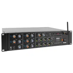
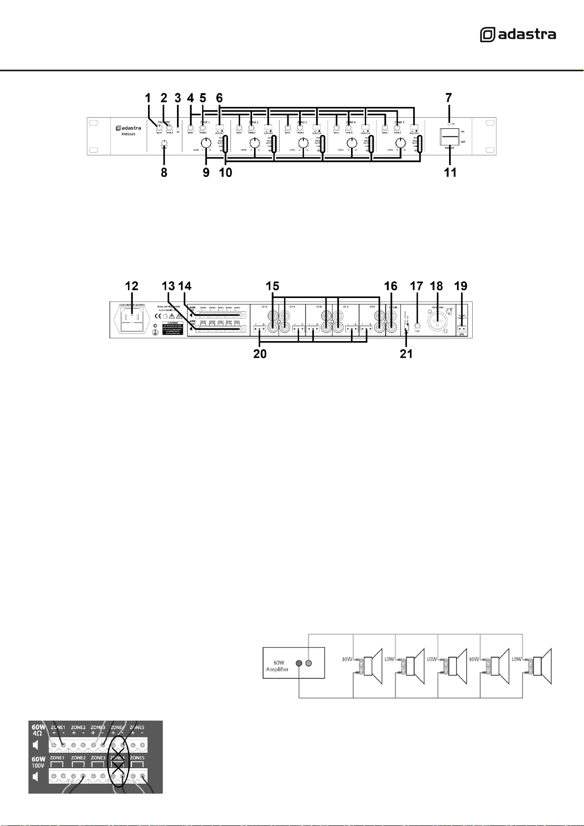
Front panel
Rear panel
Connection
Ensure the Power (11) is switched off until all input and output connections are in place.
Turn all output rotary level controls (9) fully down (anti-clockwise) to avoid loud noises when switching on.
Set the BASS and TREBLE Tone controls (1, 2, 4, 5) to the vertical position (zero)
Loudspeakers should be connected to the RMS605 via screw terminals on one of 2 removable modular connectors.
If the speaker(s) being connected is not 100V type, use the terminal block marked “4Ω” for this channel (14).
Connect + and – wires to each speaker as indicated, ensuring that there is no chance of strands shorting across terminals.
Important: Ensure that the load is no lower than 4Ω for each output. This can be…
1 x 4Ω speaker 1 x 16Ω speaker
1 x 8Ω speakers 2 x 16Ω speakers wired in parallel (8Ω)
2 x 8Ω speakers wired in parallel (4Ω) 3 x 16Ω speakers wired in parallel (5.3Ω)
4 x 16Ω speakers wired in parallel (4Ω)
Ensure that the connected speakers can handle 60W from each output.
If the speaker(s) being connected to an output channel
are 100V type, use the terminal block marked “100V” for
this output channel. When connecting multiple 100V
speakers to this output, connect all speakers in parallel
and ensure that the total load is below 54W.
The wattage of each speaker can sometimes be
adjusted via tappings on the speaker (check the
speaker’s documentation if unsure)
DO NOT connect to both 4Ω and 100V terminals for any individual output channel
DO NOT mix 4Ω and 100V speakers on any single output.
THERE SHOULD BE NO CONNECTION MADE VERTICALLY ABOVE OR BELOW ANY OTHER
1.
BASS EQ – Paging Mic input
7.
Power on indicator
2.
TREBLE EQ – Paging Mic input
8.
GAIN control – Paging Mic input
3.
Signal indicator – Paging Mic input
9.
LEVEL control – Output channels
4.
BASS EQ – Output channels
10.
Status indicators – Output channels
5.
TREBLE EQ – Output channels
11.
Power on/off switch
6.
AUX/Individual channel input switch
12.
IEC mains inlet and fuse holder
17.
Paging mic VOX sensitivity control
13.
100V speaker output terminals
18.
Paging mic balanced XLR input
14.
4Ω speaker output terminals
19.
24V emergency mute terminals
15.
Line level individual channel RCA inputs
20.
Line level individual channel terminal inputs
16.
Line level AUX RCA inputs
21.
Phantom power and Vox DIP switches
953.152UK User Manual
The RMS605 has 5 independent speaker output channels and can be used as a 5-way slave amplifier.
Set each AUX/CH switch (6) to the ‘out’ position (for individual channel input)
If connecting input to a channel via the pair of RCA inputs (15), these will be summed to mono.
If connecting input to a channel via Euroblock terminals (20), the green block may be removed from the panel for ease of handling.
Connect the signal “+” connection to the “+” screw terminal and the “-” connection to the “-” screw terminal.
If there is a separate “ground” connection (i.e. balanced cable), connect this to the “G” terminal.
Otherwise, for unbalanced connections, connect to “+” and “G” (or link both “-” and “G” connections with a piece of wire)
If 2 or more channels will share the same audio source, there is an option to connect this to the AUX input (16)
To route the AUX to any of the output channels, press the AUX/CH switch to the ‘in’ position for each channel to receive the AUX input.
For convenience, the AUX/CH switch can be switched in our out whenever AUX or individual channel input is needed.
For announcements and alerts, there is a PAGING MIC XLR input on the rear panel (18)
Connect a microphone to this input if required and select the PHANTOM power DIP switch (21) to “on” if it is a condenser microphone
which requires external phantom power from the XLR connector. Next to the PHANTOM power DIP switch is the VOX DIP switch for
voice override. Switching this to the “on” position will cause all other inputs to be muted when a sound is detected through the paging
microphone input. The amount by which this muting takes effect is adjusted using the “VOX” rotary trim control (17)
The PAGING MICROPHONE input is always live to all output channels and the GAIN (8) or signal level control and BASS + TREBLE tone
controls (1, 2) for this input are located on the front panel. If the microphone is too quiet, increase the GAIN control or if it is too loud,
turn this control down. Adjust the BASS and TREBLE controls to achieve the required tonal balance for the microphone output.
If available, connect a 24V trigger from an alarm panel to the alarm contacts (17) to mute all except channel 1 in an emergency.
Connect the rear IEC inlet (16) to the mains using the supplied mains lead (or an equivalent approved type).
Ensure that the supply voltage is correct for this equipment and that the mains outlet is switched on.
Operation
When all signal and speaker connections are made, power up the RMS605 and gradually increase the LEVEL control of each channel to
check the output to the 5 zones. Adjust the levels to the required amount and use the BASS and TREBLE controls to adjust the tone as
necessary. For each, the 12 o’clock position is zero and rotating left decreases the amount of bass or treble whilst rotating right
increases the amount of bass or treble.
Test the PAGING MIC input by gradually adjusting the GAIN control to the level needed to hear the microphone clearly through all
channels. Again, adjust BASS and TREBLE controls to ensure that the paging mic output is clear and intelligible. If the VOX function is
being used, adjust the VOX control on the rear panel to the sensitivity required to hear announcements over background music.
If needed, test the emergency mute contacts (19) by applying 24V across the terminals as indicated – all inputs except for the paging
microphone should be muted.
After use, turn down all LEVEL controls before powering down to avoid loud pops or clicks through the connected speakers.
Specifications
Power supply
170-264Vac, 50/60Hz (IEC)
Fuse
T5AL (250V)
Output Per Channel RMS @ 100V
60Wrms
Output Per Channel RMS @ 4Ω
60Wrms
Output Per Channel RMS @ 8Ω
34Wrms
Output Per Channel RMS @ 16Ω
18Wrms
Inputs
1 x mic (XLR) + 5 line inputs (L+R RCA or +/-/GND terminals) + 1 Aux input (L+R RCA)
Speaker outputs
Ch1-5 100V or Ch1-5 4Ω (Euroblock screw terminals)
Input sensitivity
-24dBV (mic), -10dBV (line/aux)
Frequency response
100Hz – 20kHz
THD
1.0%
SNR
80dB (line), 75dB (mic)
Dimensions
482 x 302 x 44mm
Weight
8.3kg
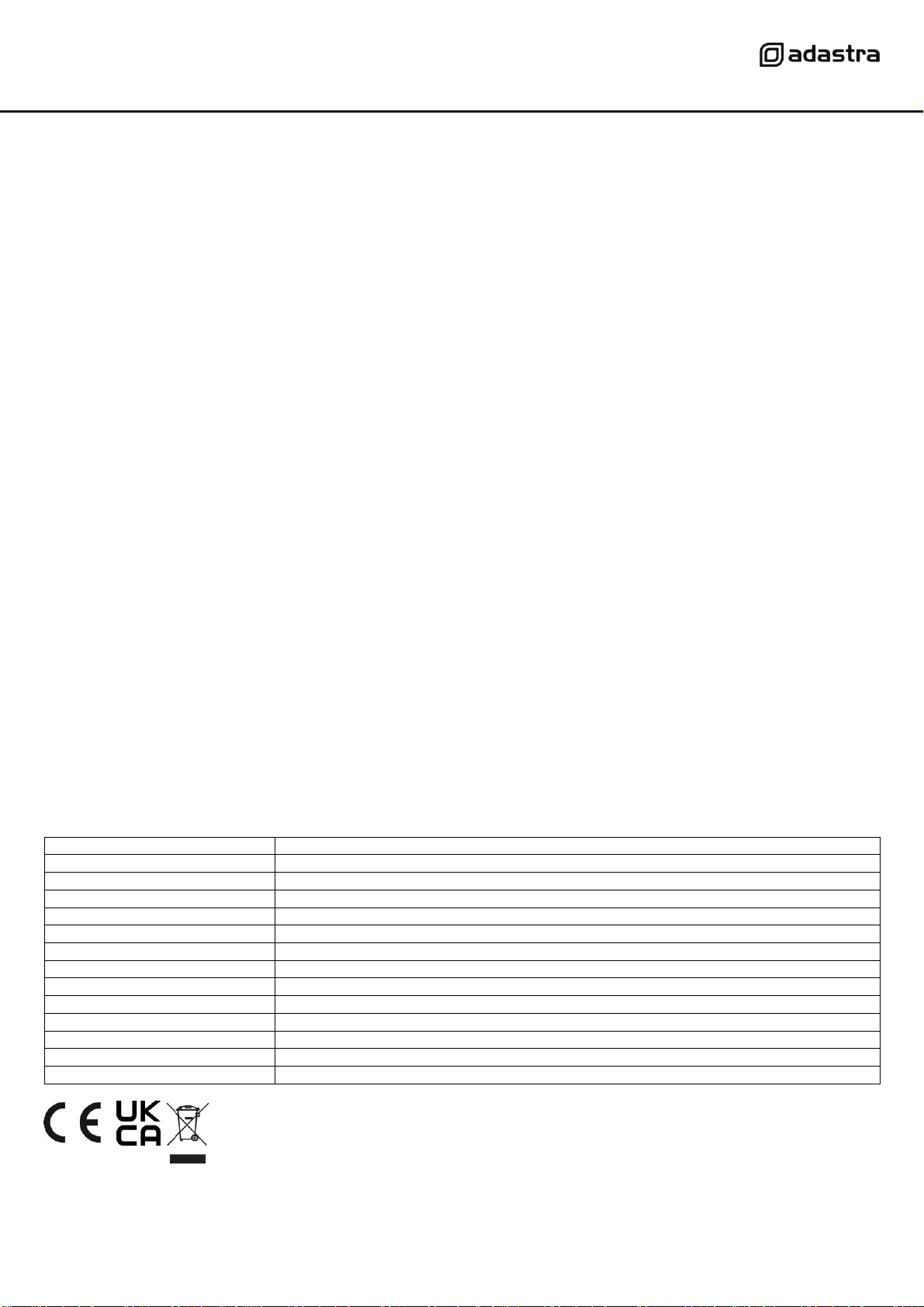
Disposal: The “Crossed Wheelie Bin” symbol on the product means that the product is classed as Electrical or
Electronic equipment and should not be disposed with other household or commercial waste at the end of its useful life
The goods must be disposed of according to your local council guidelines.
Errors and omissions excepted. Copyright© 2021.
AVSL Group Ltd. Unit 2-4 Bridgewater Park, Taylor Rd. Manchester. M41 7JQ
AVSL (EUROPE) Ltd, Unit 3D North Point House, North Point Business Park, New Mallow Road, Cork, Ireland.